EP0617536A1 - Portable and compact radiotelephone terminal - Google Patents
Portable and compact radiotelephone terminal Download PDFInfo
- Publication number
- EP0617536A1 EP0617536A1 EP94400621A EP94400621A EP0617536A1 EP 0617536 A1 EP0617536 A1 EP 0617536A1 EP 94400621 A EP94400621 A EP 94400621A EP 94400621 A EP94400621 A EP 94400621A EP 0617536 A1 EP0617536 A1 EP 0617536A1
- Authority
- EP
- European Patent Office
- Prior art keywords
- pallet
- base
- terminal according
- accumulator block
- terminal
- Prior art date
- Legal status (The legal status is an assumption and is not a legal conclusion. Google has not performed a legal analysis and makes no representation as to the accuracy of the status listed.)
- Granted
Links
- WHXSMMKQMYFTQS-UHFFFAOYSA-N Lithium Chemical compound [Li] WHXSMMKQMYFTQS-UHFFFAOYSA-N 0.000 claims description 3
- 229910052744 lithium Inorganic materials 0.000 claims description 3
- 229910052739 hydrogen Inorganic materials 0.000 claims description 2
- 239000001257 hydrogen Substances 0.000 claims description 2
- PXHVJJICTQNCMI-UHFFFAOYSA-N Nickel Chemical compound [Ni] PXHVJJICTQNCMI-UHFFFAOYSA-N 0.000 description 3
- RYGMFSIKBFXOCR-UHFFFAOYSA-N Copper Chemical compound [Cu] RYGMFSIKBFXOCR-UHFFFAOYSA-N 0.000 description 1
- 240000008042 Zea mays Species 0.000 description 1
- 229910052793 cadmium Inorganic materials 0.000 description 1
- BDOSMKKIYDKNTQ-UHFFFAOYSA-N cadmium atom Chemical compound [Cd] BDOSMKKIYDKNTQ-UHFFFAOYSA-N 0.000 description 1
- 230000000295 complement effect Effects 0.000 description 1
- 229910052802 copper Inorganic materials 0.000 description 1
- 239000010949 copper Substances 0.000 description 1
- 230000000694 effects Effects 0.000 description 1
- 230000002349 favourable effect Effects 0.000 description 1
- 238000003780 insertion Methods 0.000 description 1
- 230000037431 insertion Effects 0.000 description 1
- 229910052759 nickel Inorganic materials 0.000 description 1
Images
Classifications
-
- H—ELECTRICITY
- H04—ELECTRIC COMMUNICATION TECHNIQUE
- H04M—TELEPHONIC COMMUNICATION
- H04M1/00—Substation equipment, e.g. for use by subscribers
- H04M1/02—Constructional features of telephone sets
- H04M1/0202—Portable telephone sets, e.g. cordless phones, mobile phones or bar type handsets
- H04M1/026—Details of the structure or mounting of specific components
- H04M1/0262—Details of the structure or mounting of specific components for a battery compartment
-
- H—ELECTRICITY
- H04—ELECTRIC COMMUNICATION TECHNIQUE
- H04M—TELEPHONIC COMMUNICATION
- H04M1/00—Substation equipment, e.g. for use by subscribers
- H04M1/02—Constructional features of telephone sets
- H04M1/0202—Portable telephone sets, e.g. cordless phones, mobile phones or bar type handsets
- H04M1/0206—Portable telephones comprising a plurality of mechanically joined movable body parts, e.g. hinged housings
- H04M1/0208—Portable telephones comprising a plurality of mechanically joined movable body parts, e.g. hinged housings characterized by the relative motions of the body parts
- H04M1/0214—Foldable telephones, i.e. with body parts pivoting to an open position around an axis parallel to the plane they define in closed position
Definitions
- the present invention relates to a compact portable radiotelephone terminal.
- a radiotelephone terminal is a device provided in particular with an earpiece, a microphone, a dial pad and transceiver means. Such a terminal must be as compact as possible so that it can be easily manipulated near the face of the user during communications, and be as compact as possible during non-communications periods.
- the terminal For its power supply, the terminal often includes an accumulator block removably mounted on the side of the housing which is opposite the face during communication. The presence of this block gives the terminal a fairly large thickness which is not favorable to good behavior of the device during communications.
- portable terminals comprising a pallet intended to be placed substantially in front of the mouth of the user to receive the sound of the voice.
- This palette contains the microphone, or even constitutes a simple inert reflector returning the sound towards the microphone placed closer to the earpiece.
- a current trend is to make such a pivoting pallet, so that outside periods of use, the pallet is folded down on the keyboard so as to shorten the overall length. To avoid leading to additional over-thickness, the pallet is then made as thin as possible.
- the object of the invention is to provide a device which is easier to handle while being even more compact when it is not in use.
- the portable radiotelephone terminal comprising a housing, a removable accumulator block, and a pallet intended to be located in front of the mouth of the user when the terminal is in service, to receive the user's voice, is characterized in that the accumulator block is, in the assembled state, an integral part of the pallet.
- the body of the device is no longer thickened by the accumulator block.
- the pallet becomes more voluminous and its cross section is of the same order of magnitude as that of the body.
- the terminal is easier to grasp thanks to its thinner body.
- the palette becomes longer than in previous creations. If it is articulated, the terminal therefore becomes shorter in the folded state, which then reduces its size. Indeed, the total length of the terminal when the pallet is deployed varies little because it is a function of the distance between the mouth and the ear of an average user.
- the terminal comprises a body 1, one front face of which comprises an earpiece 2 in the vicinity of one of its ends.
- the body 1 is articulated to a folding pallet 3 movable by pivoting around an axis 4 between the deployed position shown in Figure 2 and the folded position shown in Figure 3.
- the pivot means comprise for example two cheeks 6 secured to the body 1 (Figure 1) to which is articulated a pin 7 secured d 'a base 8 of the pallet 3 ( Figures 2 and 3).
- a front face 9 of the base 8 is located opposite the mouth of the user communicating.
- the face 9 then returns the sound of the voice to a microphone 11 located on the front face of the body 1 between the axis 4 and the earpiece 2.
- the path of the sound is illustrated by the arrow 12.
- the pallet 3 When the pallet 3 is in the folded position, it is folded back against a part of the front face of the body comprising the microphone 11 and a dial pad 13.
- the terminal also comprises a removable accumulator block 14 which, according to the invention, is an integral part of the pallet 3 when it is in the assembled state.
- the base 8 is produced in the form of a flattened rectangular tube, open on a front face of its periphery on the side opposite the axis 4 and closed on the side of the axis 4.
- the accumulator block 14 s 'fits like a drawer in the rectangular housing 16 defined by this tube.
- a boss 17 of the block 14 engages in a corresponding recess 18 of the inner wall of the base 3 to effect a removable locking.
- Block 14 contains a rechargeable Cadmium / Nickel storage battery, or preferably a storage battery of the type known as Nickel-Metal-Hydrogen Ni (M) H, or even more preferably of the known type under the name of rechargeable Lithium. This order of preference corresponds to the order of increasing compactness.
- M Nickel-Metal-Hydrogen Ni
- the block 14 has on its front face, relative to the direction of engagement, at least two rigid contacts 19 which, when the block 14 is locked in the base 8, are supported on two elastic contacts 21 arranged at the bottom of the housing 16.
- the two contacts 21 are connected by a flexible cable 22 with the electronics located inside the body 1.
- the cable 22 is preferably of the flat copper type.
- the cable 22 can for example circulate between the pin 7 and a tongue in the form of a cylindrical sector 23 also integral with the base 8.
- the tongue 23 is coaxial with the pin 7 and surrounds the latter at a certain radial distance.
- the housing 1 has on its rear face a lip 24 ensuring a certain seal with the tongue 23 whatever the angular position of the base 8 around the axis 4 relative to the housing 1, and in particular in its two extreme positions.
- the block 14 has at its end opposite the rigid contacts 9 a gripping region 26 which remains visible outside the housing 16 when the block 14 is in the service position.
- the front face of the body 1 has in the region which is covered by the pallet 3 in the folded position, a recess 27 of sufficient depth to accommodate the thickness of the folded pallet, so that a rear face 28 of the pallet 8 is substantially in the extension of the non-detached part 29 of the front face 1 when the pallet is folded.
- this region 29 includes, in addition to the earpiece 2, a display screen 31 allowing the user to perceive certain information even when the pallet 8 is folded, while the terminal is operating on standby.
- the pallet could be fixed.
- the microphone could be housed in the palette so as to capture the voice directly, and no longer by reflection.
- the accumulator block could engage laterally in the pallet, for example in a lateral opening of the base.
- the accumulator block itself constitutes almost the entire pallet and in particular defines the surface for reflecting sound towards the microphone.
- the base is only a short mount articulated to the body. One can even completely remove the base, the block then comprising hinge means which can be snapped onto complementary means carried by the body 1, with a system of rotating contacts in this hinge.
Landscapes
- Engineering & Computer Science (AREA)
- Signal Processing (AREA)
- Telephone Set Structure (AREA)
- Telephone Function (AREA)
- Burglar Alarm Systems (AREA)
- Transceivers (AREA)
- Fittings On The Vehicle Exterior For Carrying Loads, And Devices For Holding Or Mounting Articles (AREA)
Abstract
Description
La présente invention concerne un terminal radiotéléphonique portatif compact.The present invention relates to a compact portable radiotelephone terminal.
On appelle terminal radiotéléphonique un appareil muni notamment d'un écouteur, d'un micro, d'un clavier de numérotation et de moyens émetteurs-récepteurs. Un tel terminal doit être aussi compact que possible pour pouvoir être aisément manipulé à proximité du visage de l'utilisateur pendant les communications, et être aussi peu encombrant que possible pendant les périodes hors communications.A radiotelephone terminal is a device provided in particular with an earpiece, a microphone, a dial pad and transceiver means. Such a terminal must be as compact as possible so that it can be easily manipulated near the face of the user during communications, and be as compact as possible during non-communications periods.
Pour son alimentation, le terminal comporte souvent un bloc accumulateur monté de manière amovible du côté du boîtier qui est opposé au visage pendant la communication. La présence de ce bloc donne au terminal une épaisseur assez importante peu favorable à une bonne tenue de l'appareil pendant les communications.For its power supply, the terminal often includes an accumulator block removably mounted on the side of the housing which is opposite the face during communication. The presence of this block gives the terminal a fairly large thickness which is not favorable to good behavior of the device during communications.
Par ailleurs, on connaît les terminaux portatifs comportant une palette destinée à se placer sensiblement devant la bouche de l'utilisateur pour recevoir le son de la voix. Cette palette contient le microphone, ou encore constitue un simple réflecteur inerte renvoyant le son vers le microphone placé plus près de l'écouteur. Une tendance actuelle consiste à réaliser une telle palette pivotante, de manière qu'en dehors des périodes d'utilisation, la palette soit rabattue sur le clavier de manière à raccourcir l'encombrement en longueur. Pour éviter d'aboutir à une sur-épaisseur supplémentaire, la palette est alors réalisée aussi mince que possible.Furthermore, portable terminals are known comprising a pallet intended to be placed substantially in front of the mouth of the user to receive the sound of the voice. This palette contains the microphone, or even constitutes a simple inert reflector returning the sound towards the microphone placed closer to the earpiece. A current trend is to make such a pivoting pallet, so that outside periods of use, the pallet is folded down on the keyboard so as to shorten the overall length. To avoid leading to additional over-thickness, the pallet is then made as thin as possible.
Le but de l'invention est de proposer un appareil qui soit plus aisé à manipuler tout en étant encore plus compact lorsqu'il est inutilisé.The object of the invention is to provide a device which is easier to handle while being even more compact when it is not in use.
Suivant l'invention, le terminal radiotéléphonique portatif, comprenant un boîtier, un bloc accumulateur amovible, et une palette destinée à se trouver devant la bouche de l'utilisateur lorsque le terminal est en service, pour recevoir la voix de l'utilisateur, est caractérisé en ce que le bloc accumulateur est, à l'état monté, partie intégrante de la palette.According to the invention, the portable radiotelephone terminal, comprising a housing, a removable accumulator block, and a pallet intended to be located in front of the mouth of the user when the terminal is in service, to receive the user's voice, is characterized in that the accumulator block is, in the assembled state, an integral part of the pallet.
Grâce à cette disposition, le corps de l'appareil n'est plus surépaissi par le bloc accumulateur. Au contraire, la palette devient plus volumineuse et sa section transversale est du même ordre de grandeur que celle du corps. Le terminal est plus facile à saisir grâce à son corps plus mince.Thanks to this arrangement, the body of the device is no longer thickened by the accumulator block. On the contrary, the pallet becomes more voluminous and its cross section is of the same order of magnitude as that of the body. The terminal is easier to grasp thanks to its thinner body.
La palette devient plus longue que dans les réalisations antérieures. Si elle est articulée, le terminal devient donc plus court à l'état replié, ce qui réduit alors son encombrement. En effet, la longueur totale du terminal lorsque la palette est déployée varie peu car elle est fonction de la distance entre la bouche et l'oreille d'un utilisateur moyen.The palette becomes longer than in previous creations. If it is articulated, the terminal therefore becomes shorter in the folded state, which then reduces its size. Indeed, the total length of the terminal when the pallet is deployed varies little because it is a function of the distance between the mouth and the ear of an average user.
D'autres particularités et avantages de l'invention ressortiront encore de la description ci-après, relative à un exemple non limitatif.Other features and advantages of the invention will emerge from the description below, relating to a non-limiting example.
Aux dessins annexés
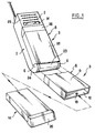
- la figure 1 est une vue du terminal en position repliée, avec en outre la représentation partielle du socle de la palette à l'état déployé, et représentation du bloc accumulateur destiné à s'y insérer ;
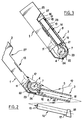
- la figure 2 est une vue partielle du terminal, partiellement en coupe, avec le bloc accumulateur prêt à s'insérer dans le socle de la palette déployée ; et
- la figure 3 est une vue analogue à la figure 2 mais avec la palette repliée et le bloc accumulateur en place.
- Figure 1 is a view of the terminal in the folded position, with further the partial representation of the base of the pallet in the deployed state, and representation of the accumulator block intended to be inserted therein;
- Figure 2 is a partial view of the terminal, partially in section, with the accumulator block ready to be inserted into the base of the deployed pallet; and
- Figure 3 is a view similar to Figure 2 but with the pallet folded and the accumulator block in place.
Dans l'exemple représenté aux figures, le terminal comprend un corps 1 dont une face frontale comporte un écouteur 2 au voisinage de l'une de ses extrémités. A son autre extrémité, le corps 1 est articulé à une palette repliable 3 mobile par pivotement autour d'un axe 4 entre la position déployée représentée à la figure 2 et la position repliée représentée à la figure 3. Comme représenté à la figure 1, les moyens de pivotement comprennent par exemple deux joues 6 solidaires du corps 1 (figure 1) auxquelles est articulé un tourillon 7 solidaire d'un socle 8 de la palette 3 (figures 2 et 3).In the example shown in the figures, the terminal comprises a
Lorsque la palette 3 est déployée (bas de la figure 1 et figure 2), une face avant 9 du socle 8 est située en face de la bouche de l'utilisateur en train de communiquer. La face 9 renvoie alors le son de la voix vers un microphone 11 situé sur la face avant du corps 1 entre l'axe 4 et l'écouteur 2. Le trajet du son est illustré par la flèche 12.When the
Lorsque la palette 3 est en position repliée, elle est rabattue contre une partie de la face avant du corps comportant le microphone 11 et un clavier de numérotation 13.When the
Le terminal comprend en outre un bloc accumulateur amovible 14 qui, conformément à l'invention, fait partie intégrante de la palette 3 lorsqu'il est à l'état monté.The terminal also comprises a
A cet effet, le socle 8 est réalisé sous la forme d'un tube rectangulaire applati, ouvert sur une face frontale de sa périphérie du côté opposé à l'axe 4 et fermé du côté de l'axe 4. Le bloc accumulateur 14 s'emboîte à la manière d'un tiroir dans le logement parallélipipédique 16 défini par ce tube. En fin d'insertion, un bossage 17 du bloc 14 s'engage dans un évidement correspondant 18 de la paroi intérieure du socle 3 pour effectuer un verrouillage amovible.To this end, the
Le bloc 14 contient une batterie d'accumulateur rechargeable au Cadmium/Nickel, ou de préférence une batterie d'accumulateur du type connu sous le nom de Nickel-Métal-Hydrogène Ni(M)H, ou de manière encore plus préférable du type connu sous le nom de Lithium rechargeable. Cet ordre de préférence correspond à l'ordre de compacité croissante.
Le bloc 14 comporte sur sa face avant, relativement au sens d'engagement, au moins deux contacts rigides 19 qui, lorsque le bloc 14 est verrouillé dans le socle 8, sont en appui sur deux contacts élastiques 21 aménagés au fond du logement 16. Les deux contacts 21 sont reliés par un câble souple 22 avec l'électronique située à l'intérieur du corps 1. Le câble 22 est de préférence du type plat en cuivre.The
Le câble 22 peut par exemple circuler entre le tourillon 7 et une languette en forme de secteur cylindrique 23 également solidaire du socle 8. La languette 23 est coaxiale avec le tourillon 7 et entoure celui-ci à une certaine distance radiale. Le boîtier 1 comporte sur sa face arrière une lèvre 24 assurant une certaine étanchéité avec la languette 23 quelle que soit la position angulaire du socle 8 autour de l'axe 4 par rapport au boîtier 1, et notamment en ses deux positions extrêmes.The
Le bloc 14 comporte à son extrémité opposée aux contacts rigides 9 une région de préhension 26 qui reste apparente à l'extérieur du logement 16 quand le bloc 14 est en position de service.The
La face avant du corps 1 présente dans la région qui est recouverte par la palette 3 en position repliée, un décrochement 27 d'une profondeur suffisante pour accueillir l'épaisseur de la palette repliée, de façon qu'une face arrière 28 de la palette 8 soit sensiblement dans le prolongement de la partie non décrochée 29 de la face avant 1 lorsque la palette est repliée. Comme représenté à la figure 1, cette région 29 comporte en plus de l'écouteur 2, un écran de visualisation 31 permettant à l'utilisateur de percevoir certaines informations même lorsque la palette 8 est repliée, alors que le terminal fonctionne en attente.The front face of the
Bien entendu, l'invention n'est pas limitée à l'exemple décrit et représenté.Of course, the invention is not limited to the example described and shown.
La palette pourrait être fixe.The pallet could be fixed.
Notamment si le type d'accumulateur utilisé est peu encombrant, en particulier dans le cas des accumulateurs du type Lithium rechargeable, on pourrait loger le micro dans la palette de manière à capter directement la voix, et non plus par réflexion.In particular if the type of accumulator used is compact, in particular in the case of rechargeable Lithium type accumulators, the microphone could be housed in the palette so as to capture the voice directly, and no longer by reflection.
Le bloc accumulateur pourrait s'engager latéralement dans la palette, par exemple dans une ouverture latérale du socle.The accumulator block could engage laterally in the pallet, for example in a lateral opening of the base.
Il est également concevable que le bloc accumulateur constitue lui-même la quasi-totalité de la palette et définisse en particulier la surface de réflexion du son vers le microphone. Dans ce cas, le socle n'est plus qu'une courte monture articulée au corps. On peut même faire disparaître totalement le socle, le bloc comportant alors des moyens d'articulation encliquetables sur des moyens complémentaires portés par le corps 1, avec un système de contacts tournants dans cette articulation.It is also conceivable that the accumulator block itself constitutes almost the entire pallet and in particular defines the surface for reflecting sound towards the microphone. In this case, the base is only a short mount articulated to the body. One can even completely remove the base, the block then comprising hinge means which can be snapped onto complementary means carried by the
Claims (9)
Applications Claiming Priority (2)
| Application Number | Priority Date | Filing Date | Title |
|---|---|---|---|
| FR9303315 | 1993-03-23 | ||
| FR9303315A FR2703203B1 (en) | 1993-03-23 | 1993-03-23 | Compact portable radiotelephone terminal. |
Publications (2)
| Publication Number | Publication Date |
|---|---|
| EP0617536A1 true EP0617536A1 (en) | 1994-09-28 |
| EP0617536B1 EP0617536B1 (en) | 2001-05-16 |
Family
ID=9445244
Family Applications (1)
| Application Number | Title | Priority Date | Filing Date |
|---|---|---|---|
| EP94400621A Expired - Lifetime EP0617536B1 (en) | 1993-03-23 | 1994-03-23 | Portable and compact radiotelephone terminal |
Country Status (7)
| Country | Link |
|---|---|
| US (1) | US6665550B1 (en) |
| EP (1) | EP0617536B1 (en) |
| AT (1) | ATE201297T1 (en) |
| AU (1) | AU679478B2 (en) |
| DE (1) | DE69427204T2 (en) |
| DK (1) | DK0617536T3 (en) |
| FR (1) | FR2703203B1 (en) |
Cited By (3)
| Publication number | Priority date | Publication date | Assignee | Title |
|---|---|---|---|---|
| GB2302232A (en) * | 1995-06-13 | 1997-01-08 | Motorola Inc | Portable electronic device and method for coupling power thereto |
| GB2401727A (en) * | 2003-05-16 | 2004-11-17 | Inquam | Electronic device with battery slot |
| EP0782368A3 (en) * | 1995-12-27 | 2006-05-03 | AT&T Corp. | Collapsible image derived differential microphone |
Families Citing this family (14)
| Publication number | Priority date | Publication date | Assignee | Title |
|---|---|---|---|---|
| KR20010086781A (en) * | 2000-03-03 | 2001-09-15 | 임성묵 | Mobile phone with a solar cell |
| US6775129B1 (en) * | 2003-02-14 | 2004-08-10 | Intel Corporation | Convertible and detachable laptops |
| USD509494S1 (en) * | 2003-10-31 | 2005-09-13 | Samsung Electronics Co., Ltd. | Cellular phone |
| USD522987S1 (en) * | 2003-11-13 | 2006-06-13 | Vodafone K.K. | Cell phone |
| USD515056S1 (en) * | 2003-11-13 | 2006-02-14 | Vodafone K.K. | Cell phone |
| USD524273S1 (en) * | 2003-11-13 | 2006-07-04 | Vodafone K.K. | Cell phone |
| USD515057S1 (en) * | 2003-11-13 | 2006-02-14 | Vodafone K.K. | Cell phone |
| US7483727B2 (en) * | 2005-04-04 | 2009-01-27 | Research In Motion Limited | Mobile wireless communications device having improved antenna impedance match and antenna gain from RF energy |
| KR101366219B1 (en) * | 2008-09-09 | 2014-02-21 | 제로 크로마, 엘엘씨 | Holder for electronic device with support |
| US8960634B2 (en) | 2008-09-09 | 2015-02-24 | Zero Chroma, LLC | Holder for electronic device with support |
| US8382059B2 (en) * | 2008-09-09 | 2013-02-26 | Zero Chroma, LLC | Holder for electronic device with support |
| US20100151911A1 (en) | 2008-11-26 | 2010-06-17 | Anthony W. Mazzeo | Integrated telecommunications handset |
| USD612823S1 (en) * | 2008-11-26 | 2010-03-30 | Anthony W. Mazzeo | Handset |
| USD698543S1 (en) | 2012-10-19 | 2014-02-04 | Zerochroma, LLC | Portion of holder for electronic device |
Citations (5)
| Publication number | Priority date | Publication date | Assignee | Title |
|---|---|---|---|---|
| FR2601211A1 (en) * | 1986-07-04 | 1988-01-08 | Mecelec Sa | Portable telephone handset for communication systems of the public type |
| EP0275996A2 (en) * | 1987-01-23 | 1988-07-27 | Siemens Aktiengesellschaft | Handset for a telephone apparatus with a lid covering the keyboard |
| US5027394A (en) * | 1987-09-30 | 1991-06-25 | Matsushita Electric Industrial Co., Ltd. | Folding type telephone containing a wound electrical connection |
| WO1991014332A1 (en) * | 1990-03-05 | 1991-09-19 | Motorola, Inc. | Radio telephone with secondary charging capability |
| JPH04307841A (en) * | 1991-04-05 | 1992-10-30 | Hitachi Ltd | Portable telephone set |
Family Cites Families (12)
| Publication number | Priority date | Publication date | Assignee | Title |
|---|---|---|---|---|
| US4845772A (en) * | 1988-06-13 | 1989-07-04 | Motorola, Inc. | Portable radiotelephone with control switch disabling |
| JPS6425027A (en) | 1987-07-21 | 1989-01-27 | Asahi Glass Co Ltd | Measuring method of amount of eccentricity between core and clad of optical fiber and direction of eccentricity |
| DE69105221T2 (en) * | 1990-03-07 | 1995-06-08 | Sony Corp | Radio telephone set. |
| JPH04117849A (en) * | 1990-09-07 | 1992-04-17 | Fujitsu Ltd | Card type telephone set |
| US5278993A (en) | 1991-02-01 | 1994-01-11 | Motorola, Inc. | Integral spring loaded hinge and switch for portable radio device |
| US5117073A (en) * | 1991-04-02 | 1992-05-26 | Motorola, Inc. | Control signal initiator responsive to a hinge position |
| JPH05153216A (en) | 1991-11-25 | 1993-06-18 | Sanyo Electric Co Ltd | Portable unit |
| US5335276A (en) * | 1992-12-16 | 1994-08-02 | Texas Instruments Incorporated | Communication system and methods for enhanced information transfer |
| US5548824A (en) * | 1993-08-25 | 1996-08-20 | Mitsubishi Denki Kabushiki Kaisha | Portable radio communication device housing having a battery storage unit |
| US5517683A (en) * | 1995-01-18 | 1996-05-14 | Cycomm Corporation | Conformant compact portable cellular phone case system and connector |
| US5832079A (en) * | 1996-05-03 | 1998-11-03 | Ericsson Inc. | Acoustic horn for use in cellular flip phones |
| US5915015A (en) * | 1996-09-10 | 1999-06-22 | Ericsson, Inc. | Telephone having sealed acoustical passageway through flip cover hinge |
-
1993
- 1993-03-23 FR FR9303315A patent/FR2703203B1/en not_active Expired - Fee Related
-
1994
- 1994-03-18 AU AU57913/94A patent/AU679478B2/en not_active Ceased
- 1994-03-23 DK DK94400621T patent/DK0617536T3/en active
- 1994-03-23 AT AT94400621T patent/ATE201297T1/en not_active IP Right Cessation
- 1994-03-23 EP EP94400621A patent/EP0617536B1/en not_active Expired - Lifetime
- 1994-03-23 DE DE69427204T patent/DE69427204T2/en not_active Expired - Lifetime
-
1998
- 1998-01-05 US US09/002,950 patent/US6665550B1/en not_active Expired - Lifetime
Patent Citations (5)
| Publication number | Priority date | Publication date | Assignee | Title |
|---|---|---|---|---|
| FR2601211A1 (en) * | 1986-07-04 | 1988-01-08 | Mecelec Sa | Portable telephone handset for communication systems of the public type |
| EP0275996A2 (en) * | 1987-01-23 | 1988-07-27 | Siemens Aktiengesellschaft | Handset for a telephone apparatus with a lid covering the keyboard |
| US5027394A (en) * | 1987-09-30 | 1991-06-25 | Matsushita Electric Industrial Co., Ltd. | Folding type telephone containing a wound electrical connection |
| WO1991014332A1 (en) * | 1990-03-05 | 1991-09-19 | Motorola, Inc. | Radio telephone with secondary charging capability |
| JPH04307841A (en) * | 1991-04-05 | 1992-10-30 | Hitachi Ltd | Portable telephone set |
Non-Patent Citations (2)
| Title |
|---|
| CLOKE: "STROMVERSORGUNG SCHNURLOSER TELEFONAPPARATE", NACHRICHTENTECHNISCHE ZEITSCHRIFT, vol. 40, no. 4, April 1987 (1987-04-01), BERLIN, pages 302 - 303, XP000764993 * |
| PATENT ABSTRACTS OF JAPAN vol. 17, no. 137 (E - 1335) 22 March 1993 (1993-03-22) * |
Cited By (6)
| Publication number | Priority date | Publication date | Assignee | Title |
|---|---|---|---|---|
| GB2302232A (en) * | 1995-06-13 | 1997-01-08 | Motorola Inc | Portable electronic device and method for coupling power thereto |
| US5857148A (en) * | 1995-06-13 | 1999-01-05 | Motorola, Inc. | Portable electronic device and method for coupling power thereto |
| GB2302232B (en) * | 1995-06-13 | 1999-06-30 | Motorola Inc | Portable electronic device and method for coupling power thereto |
| US6141569A (en) * | 1995-06-13 | 2000-10-31 | Motorola, Inc. | Portable electronic device and method of coupling power thereto |
| EP0782368A3 (en) * | 1995-12-27 | 2006-05-03 | AT&T Corp. | Collapsible image derived differential microphone |
| GB2401727A (en) * | 2003-05-16 | 2004-11-17 | Inquam | Electronic device with battery slot |
Also Published As
| Publication number | Publication date |
|---|---|
| DE69427204T2 (en) | 2002-01-03 |
| DE69427204D1 (en) | 2001-06-21 |
| FR2703203A1 (en) | 1994-09-30 |
| ATE201297T1 (en) | 2001-06-15 |
| DK0617536T3 (en) | 2001-08-27 |
| US6665550B1 (en) | 2003-12-16 |
| EP0617536B1 (en) | 2001-05-16 |
| AU679478B2 (en) | 1997-07-03 |
| FR2703203B1 (en) | 1995-04-28 |
| AU5791394A (en) | 1994-09-29 |
Similar Documents
| Publication | Publication Date | Title |
|---|---|---|
| EP0617536B1 (en) | Portable and compact radiotelephone terminal | |
| EP0469503B1 (en) | Apparatus for the receipt of memory card | |
| EP0890248A1 (en) | Telephone handset convertible into a telephone headset | |
| FR2916929A1 (en) | PORTABLE TERMINAL | |
| FR2899726A1 (en) | BATTERY PACK FOR ELECTRICAL APPARATUS. | |
| EP3333870B1 (en) | Electrical switch | |
| FR2781113A1 (en) | PORTABLE ELECTRONIC DEVICE, ITS CASE AND ITS BATTERY STORE | |
| FR2909167A1 (en) | LASER LEVELING DEVICE | |
| EP1297723A1 (en) | Mobile illuminating device | |
| FR2839393A1 (en) | ARRANGEMENT OF A FEMALE ELEMENT AND MOBILE DEVICE. | |
| FR2709032A1 (en) | Lock system. | |
| EP2710445A1 (en) | Protective case for a game console | |
| CA2226413A1 (en) | Power supply for a portable device, of the type allowing the use of different types of supply, and corresponding portable device | |
| EP3840136B1 (en) | Mechanism for electrical equipment, associated electrical assembly and electrical equipment | |
| EP4078641A1 (en) | Mechanism for an electrical switch, electrical assembly and electrical switch thereof | |
| EP2527717B1 (en) | Power supply device of a portable lamp | |
| FR3094973A1 (en) | Protective case for wireless earphone charger | |
| FR2624714A1 (en) | MANUAL DUST ASPIRATOR, IN PARTICULAR SMALL MODEL | |
| EP3840003A1 (en) | Trim and electrical switch comprising such a trim | |
| EP4356806A1 (en) | Vacuum cleaner suction tube with a hinge device | |
| FR2826706A1 (en) | Mobile lighting fitting for workshop use, comprises array of luminescent diodes and associated electronic control equipment mounted on panel and contained inside box with hook, window and cable entry | |
| FR2821975A1 (en) | Mobile phone three position pivot for keyboard cover, has intermediate fitting partially containing two separate hinges which allow the cover to move from its closed position to two other stable open positions | |
| FR2649565A1 (en) | ACOUSTIC COUPLING DEVICE FOR MEASURING TELEPHONOMETRIC MEASUREMENTS AND / OR CHECKS ON TELEPHONE HANDSETS | |
| FR2754217A1 (en) | Support arm for detachable automobile sun-visor | |
| FR2773936A1 (en) | MOBILE TELEPHONE DEVICE WITH AMPLIFIED LISTENING |
Legal Events
| Date | Code | Title | Description |
|---|---|---|---|
| PUAI | Public reference made under article 153(3) epc to a published international application that has entered the european phase |
Free format text: ORIGINAL CODE: 0009012 |
|
| AK | Designated contracting states |
Kind code of ref document: A1 Designated state(s): AT BE DE DK ES FR GB IT NL SE |
|
| RAP1 | Party data changed (applicant data changed or rights of an application transferred) |
Owner name: ALCATEL MOBILE COMMUNICATION FRANCE |
|
| 17P | Request for examination filed |
Effective date: 19950202 |
|
| 17Q | First examination report despatched |
Effective date: 19970905 |
|
| RIC1 | Information provided on ipc code assigned before grant |
Free format text: 7H 04M 1/02 A |
|
| GRAG | Despatch of communication of intention to grant |
Free format text: ORIGINAL CODE: EPIDOS AGRA |
|
| GRAG | Despatch of communication of intention to grant |
Free format text: ORIGINAL CODE: EPIDOS AGRA |
|
| GRAH | Despatch of communication of intention to grant a patent |
Free format text: ORIGINAL CODE: EPIDOS IGRA |
|
| GRAH | Despatch of communication of intention to grant a patent |
Free format text: ORIGINAL CODE: EPIDOS IGRA |
|
| GRAA | (expected) grant |
Free format text: ORIGINAL CODE: 0009210 |
|
| RAP1 | Party data changed (applicant data changed or rights of an application transferred) |
Owner name: ALCATEL |
|
| AK | Designated contracting states |
Kind code of ref document: B1 Designated state(s): AT BE DE DK ES FR GB IT NL SE |
|
| PG25 | Lapsed in a contracting state [announced via postgrant information from national office to epo] |
Ref country code: IT Free format text: LAPSE BECAUSE OF FAILURE TO SUBMIT A TRANSLATION OF THE DESCRIPTION OR TO PAY THE FEE WITHIN THE PRESCRIBED TIME-LIMIT;WARNING: LAPSES OF ITALIAN PATENTS WITH EFFECTIVE DATE BEFORE 2007 MAY HAVE OCCURRED AT ANY TIME BEFORE 2007. THE CORRECT EFFECTIVE DATE MAY BE DIFFERENT FROM THE ONE RECORDED. Effective date: 20010516 |
|
| REF | Corresponds to: |
Ref document number: 201297 Country of ref document: AT Date of ref document: 20010615 Kind code of ref document: T |
|
| GBT | Gb: translation of ep patent filed (gb section 77(6)(a)/1977) |
Effective date: 20010517 |
|
| REF | Corresponds to: |
Ref document number: 69427204 Country of ref document: DE Date of ref document: 20010621 |
|
| PG25 | Lapsed in a contracting state [announced via postgrant information from national office to epo] |
Ref country code: SE Free format text: LAPSE BECAUSE OF FAILURE TO SUBMIT A TRANSLATION OF THE DESCRIPTION OR TO PAY THE FEE WITHIN THE PRESCRIBED TIME-LIMIT Effective date: 20010816 |
|
| REG | Reference to a national code |
Ref country code: DK Ref legal event code: T3 |
|
| PG25 | Lapsed in a contracting state [announced via postgrant information from national office to epo] |
Ref country code: ES Free format text: LAPSE BECAUSE OF FAILURE TO SUBMIT A TRANSLATION OF THE DESCRIPTION OR TO PAY THE FEE WITHIN THE PRESCRIBED TIME-LIMIT Effective date: 20011130 |
|
| REG | Reference to a national code |
Ref country code: GB Ref legal event code: IF02 |
|
| PGFP | Annual fee paid to national office [announced via postgrant information from national office to epo] |
Ref country code: NL Payment date: 20020228 Year of fee payment: 9 |
|
| PGFP | Annual fee paid to national office [announced via postgrant information from national office to epo] |
Ref country code: DK Payment date: 20020304 Year of fee payment: 9 |
|
| PLBE | No opposition filed within time limit |
Free format text: ORIGINAL CODE: 0009261 |
|
| STAA | Information on the status of an ep patent application or granted ep patent |
Free format text: STATUS: NO OPPOSITION FILED WITHIN TIME LIMIT |
|
| PG25 | Lapsed in a contracting state [announced via postgrant information from national office to epo] |
Ref country code: AT Free format text: LAPSE BECAUSE OF FAILURE TO SUBMIT A TRANSLATION OF THE DESCRIPTION OR TO PAY THE FEE WITHIN THE PRESCRIBED TIME-LIMIT Effective date: 20020323 |
|
| PG25 | Lapsed in a contracting state [announced via postgrant information from national office to epo] |
Ref country code: BE Free format text: LAPSE BECAUSE OF NON-PAYMENT OF DUE FEES Effective date: 20020331 |
|
| 26N | No opposition filed | ||
| BERE | Be: lapsed |
Owner name: *ALCATEL Effective date: 20020331 |
|
| PG25 | Lapsed in a contracting state [announced via postgrant information from national office to epo] |
Ref country code: DK Free format text: LAPSE BECAUSE OF NON-PAYMENT OF DUE FEES Effective date: 20030331 |
|
| PG25 | Lapsed in a contracting state [announced via postgrant information from national office to epo] |
Ref country code: NL Free format text: LAPSE BECAUSE OF NON-PAYMENT OF DUE FEES Effective date: 20031001 |
|
| NLV4 | Nl: lapsed or anulled due to non-payment of the annual fee |
Effective date: 20031001 |
|
| REG | Reference to a national code |
Ref country code: FR Ref legal event code: TP |
|
| REG | Reference to a national code |
Ref country code: GB Ref legal event code: 732E |
|
| REG | Reference to a national code |
Ref country code: GB Ref legal event code: 732E Free format text: REGISTERED BETWEEN 20090924 AND 20090930 |
|
| REG | Reference to a national code |
Ref country code: GB Ref legal event code: 732E Free format text: REGISTERED BETWEEN 20120607 AND 20120613 |
|
| REG | Reference to a national code |
Ref country code: FR Ref legal event code: TP Owner name: Z124, GB Effective date: 20130201 Ref country code: FR Ref legal event code: CD Owner name: Z124, GB Effective date: 20130201 |
|
| PGFP | Annual fee paid to national office [announced via postgrant information from national office to epo] |
Ref country code: DE Payment date: 20130320 Year of fee payment: 20 Ref country code: GB Payment date: 20130320 Year of fee payment: 20 Ref country code: FR Payment date: 20130408 Year of fee payment: 20 |
|
| REG | Reference to a national code |
Ref country code: DE Ref legal event code: R071 Ref document number: 69427204 Country of ref document: DE |
|
| REG | Reference to a national code |
Ref country code: DE Ref legal event code: R071 Ref document number: 69427204 Country of ref document: DE |
|
| REG | Reference to a national code |
Ref country code: GB Ref legal event code: PE20 Expiry date: 20140322 |
|
| PG25 | Lapsed in a contracting state [announced via postgrant information from national office to epo] |
Ref country code: DE Free format text: LAPSE BECAUSE OF EXPIRATION OF PROTECTION Effective date: 20140325 Ref country code: GB Free format text: LAPSE BECAUSE OF EXPIRATION OF PROTECTION Effective date: 20140322 |