EP2527613A1 - Cooling apparatus for construction machine - Google Patents
Cooling apparatus for construction machine Download PDFInfo
- Publication number
- EP2527613A1 EP2527613A1 EP12150232A EP12150232A EP2527613A1 EP 2527613 A1 EP2527613 A1 EP 2527613A1 EP 12150232 A EP12150232 A EP 12150232A EP 12150232 A EP12150232 A EP 12150232A EP 2527613 A1 EP2527613 A1 EP 2527613A1
- Authority
- EP
- European Patent Office
- Prior art keywords
- heat exchangers
- cores
- core
- cooling
- plural number
- Prior art date
- Legal status (The legal status is an assumption and is not a legal conclusion. Google has not performed a legal analysis and makes no representation as to the accuracy of the status listed.)
- Withdrawn
Links
- 238000001816 cooling Methods 0.000 title claims abstract description 133
- 238000010276 construction Methods 0.000 title claims description 10
- 230000002093 peripheral effect Effects 0.000 claims description 13
- 239000002826 coolant Substances 0.000 description 4
- 239000012141 concentrate Substances 0.000 description 3
- 239000000428 dust Substances 0.000 description 2
- 239000012530 fluid Substances 0.000 description 2
- 238000009434 installation Methods 0.000 description 2
- 238000012986 modification Methods 0.000 description 2
- 230000004048 modification Effects 0.000 description 2
- 238000011144 upstream manufacturing Methods 0.000 description 2
- 230000010485 coping Effects 0.000 description 1
- 238000007599 discharging Methods 0.000 description 1
- 238000012423 maintenance Methods 0.000 description 1
- 239000000126 substance Substances 0.000 description 1
Images



Classifications
-
- F—MECHANICAL ENGINEERING; LIGHTING; HEATING; WEAPONS; BLASTING
- F01—MACHINES OR ENGINES IN GENERAL; ENGINE PLANTS IN GENERAL; STEAM ENGINES
- F01P—COOLING OF MACHINES OR ENGINES IN GENERAL; COOLING OF INTERNAL-COMBUSTION ENGINES
- F01P3/00—Liquid cooling
- F01P3/18—Arrangements or mounting of liquid-to-air heat-exchangers
-
- E—FIXED CONSTRUCTIONS
- E02—HYDRAULIC ENGINEERING; FOUNDATIONS; SOIL SHIFTING
- E02F—DREDGING; SOIL-SHIFTING
- E02F9/00—Component parts of dredgers or soil-shifting machines, not restricted to one of the kinds covered by groups E02F3/00 - E02F7/00
- E02F9/08—Superstructures; Supports for superstructures
- E02F9/0858—Arrangement of component parts installed on superstructures not otherwise provided for, e.g. electric components, fenders, air-conditioning units
- E02F9/0866—Engine compartment, e.g. heat exchangers, exhaust filters, cooling devices, silencers, mufflers, position of hydraulic pumps in the engine compartment
-
- F—MECHANICAL ENGINEERING; LIGHTING; HEATING; WEAPONS; BLASTING
- F28—HEAT EXCHANGE IN GENERAL
- F28D—HEAT-EXCHANGE APPARATUS, NOT PROVIDED FOR IN ANOTHER SUBCLASS, IN WHICH THE HEAT-EXCHANGE MEDIA DO NOT COME INTO DIRECT CONTACT
- F28D1/00—Heat-exchange apparatus having stationary conduit assemblies for one heat-exchange medium only, the media being in contact with different sides of the conduit wall, in which the other heat-exchange medium is a large body of fluid, e.g. domestic or motor car radiators
- F28D1/02—Heat-exchange apparatus having stationary conduit assemblies for one heat-exchange medium only, the media being in contact with different sides of the conduit wall, in which the other heat-exchange medium is a large body of fluid, e.g. domestic or motor car radiators with heat-exchange conduits immersed in the body of fluid
- F28D1/04—Heat-exchange apparatus having stationary conduit assemblies for one heat-exchange medium only, the media being in contact with different sides of the conduit wall, in which the other heat-exchange medium is a large body of fluid, e.g. domestic or motor car radiators with heat-exchange conduits immersed in the body of fluid with tubular conduits
- F28D1/0408—Multi-circuit heat exchangers, e.g. integrating different heat exchange sections in the same unit or heat exchangers for more than two fluids
- F28D1/0417—Multi-circuit heat exchangers, e.g. integrating different heat exchange sections in the same unit or heat exchangers for more than two fluids with particular circuits for the same heat exchange medium, e.g. with the heat exchange medium flowing through sections having different heat exchange capacities or for heating/cooling the heat exchange medium at different temperatures
-
- F—MECHANICAL ENGINEERING; LIGHTING; HEATING; WEAPONS; BLASTING
- F28—HEAT EXCHANGE IN GENERAL
- F28D—HEAT-EXCHANGE APPARATUS, NOT PROVIDED FOR IN ANOTHER SUBCLASS, IN WHICH THE HEAT-EXCHANGE MEDIA DO NOT COME INTO DIRECT CONTACT
- F28D1/00—Heat-exchange apparatus having stationary conduit assemblies for one heat-exchange medium only, the media being in contact with different sides of the conduit wall, in which the other heat-exchange medium is a large body of fluid, e.g. domestic or motor car radiators
- F28D1/02—Heat-exchange apparatus having stationary conduit assemblies for one heat-exchange medium only, the media being in contact with different sides of the conduit wall, in which the other heat-exchange medium is a large body of fluid, e.g. domestic or motor car radiators with heat-exchange conduits immersed in the body of fluid
- F28D1/04—Heat-exchange apparatus having stationary conduit assemblies for one heat-exchange medium only, the media being in contact with different sides of the conduit wall, in which the other heat-exchange medium is a large body of fluid, e.g. domestic or motor car radiators with heat-exchange conduits immersed in the body of fluid with tubular conduits
- F28D1/0408—Multi-circuit heat exchangers, e.g. integrating different heat exchange sections in the same unit or heat exchangers for more than two fluids
- F28D1/0426—Multi-circuit heat exchangers, e.g. integrating different heat exchange sections in the same unit or heat exchangers for more than two fluids with units having particular arrangement relative to the large body of fluid, e.g. with interleaved units or with adjacent heat exchange units in common air flow or with units extending at an angle to each other or with units arranged around a central element
- F28D1/0443—Combination of units extending one beside or one above the other
-
- F—MECHANICAL ENGINEERING; LIGHTING; HEATING; WEAPONS; BLASTING
- F01—MACHINES OR ENGINES IN GENERAL; ENGINE PLANTS IN GENERAL; STEAM ENGINES
- F01P—COOLING OF MACHINES OR ENGINES IN GENERAL; COOLING OF INTERNAL-COMBUSTION ENGINES
- F01P3/00—Liquid cooling
- F01P3/18—Arrangements or mounting of liquid-to-air heat-exchangers
- F01P2003/185—Arrangements or mounting of liquid-to-air heat-exchangers arranged in parallel
Definitions
- the present invention relates to a cooling apparatus for a construction machine.
- Patent Document As a cooling apparatus for a construction machine, there has been known one type designed to allow cooling air sucked by a cooling fan to pass through respective cores of a plural number of heat exchangers arranged in widthwise side-by-side relation to each other to thereby perform heat exchange (see, for example, JP 2010-159691A : hereinafter referred to as "Patent Document").
- the cooling apparatus disclosed in the Patent Document is primarily intended to suppress vibration and noise due to a difference in height between the cores. Thus, it is not designed considering that a variation in air volume occurs due to a difference in airflow resistance between the cores.
- the cooling apparatus disclosed in the Patent Document comprises two generally rectangular-shaped cores having different heights, wherein a region failing to overlap the projection of the cooling fan exists above an upper edge of a lower one (hereinafter referred to as "lower core") of the two cores (a relatively large region which extends beyond the upper edge of the lower core and the projection).
- the cooling fan has a circular shape, and an air-volume distribution of cooling air passing through the cores concentrates in a region corresponding to the projection of the cooling fan.
- the present invention is directed to a cooling apparatus for a construction machine, which comprises at least three heat exchangers (a plural number of heat exchangers) arranged in widthwise side-by-side relation to each other, and a cooling fan disposed opposed to the plural number of heat exchangers, and designed to provide the following solution.
- each of the plural number of heat exchangers has a core (a portion of the heat exchanger where fluid within the heat exchanger is heat-exchanged with external cooling air), wherein each of the cores of the heat exchangers disposed at widthwise opposite ends of the plural number of heat exchangers is formed to have a height lower than that of the core of the heat exchanger disposed at a center of the plural number of heat exchangers, whereby a combination of the cores of the plural number of heat exchangers is formed in a shape corresponding to a projection of the cooling fan.
- a combination of the cores of the plural number of heat exchangers is formed in a shape corresponding to a projection of the cooling fan.
- each of the cores of the heat exchangers disposed at the widthwise opposite ends of the plural number of heat exchangers is formed to have a height lower than that of the core of the heat exchanger disposed at the center of the plural number of heat exchangers.
- This structure makes it possible to optimize an air-volume distribution of cooling air passing through the cores of the plural number of heat exchangers arranged in side-by-side relation.
- the cores have a rectangular shape, whereas the cooling fan has a circular shape.
- the air-volume distribution of cooling air passing through the cores concentrates in a region corresponding to the projection of the cooling fan, and the cooling air is less likely to flow through corners of the cores.
- the height of each of the cores of the heat exchangers disposed at the widthwise opposite ends is lowered so as to allow a combination of the cores of the plural number of heat exchangers to be formed in a shape corresponding to the projection of the cooling fan.
- FIG. 1 is a side view illustrating an overall structure of a constriction machine employing a cooling apparatus according to a first embodiment of the present invention.
- the construction machine 10 is a hydraulic shovel which comprises a crawler-type base carrier 1 and a swivel upper body 2 (body frame) rotatably mounted on the base carrier 1.
- the swivel upper body 2 has a body frame 3 to which an attachment 4, a cab 5, a machine room 6, a counterweight 7, etc., are attached.
- a left side of the drawing sheet of FIG. 1 i.e., a side of the construction machine 10 at which the attachment 4 is disposed
- front (frontward) a left side of the drawing sheet of FIG. 1
- left (leftward) a front side with respect to the drawing sheet of FIG. 1
- directions, such as frontward, rearward, rightward and leftward directions, will be followed by this definition, unless otherwise mentioned.
- the attachment 4 is supported by a front and central portion of the swivel upper body 2 in a vertically swingable manner.
- the attachment 4 comprises a generally L-shaped boom 11 swingably supported by a pair of vertical plates (not illustrated) provided at approximately central positions of the body frame 3, an arm 12 provided on a longitudinal plane of the boom 11 and swingably supported by the boom 11, and a bucket 13 swingably supported by the arm 12.
- the cab 5 is a rectangular box-shaped operator's room which is internally equipped with an operator's seat, various control devices, various operating devices, etc., and disposed on a front and left side of the swivel upper body 2 so that it is located on a left side of and adjacent to the attachment 4.
- the machine room 6 is provided to extend between right and left sides of a rear portion of the swivel upper body 2.
- the counterweight 7 is provided to extend between right and left sides of a rear end of the swivel upper body 2.
- a left end of the machine room 6 is covered by a body cover 17.
- the body cover 17 has an air inlet opening 17a for taking outside air into the machine room 6.
- a right end of the machine room 6 has an air outlet opening (illustration is omitted) for discharging the intake air.
- the machine room 6 is internally provided with a cooling apparatus 20 according to a first embodiment of the present invention.
- the cooling apparatus 20 comprises a cooling fan 25, first to third heat exchangers 30, 40, 50 disposed upstream of the cooling fan 25 in an airflow direction, and a shroud 26 which covers an outer periphery of the cooling fan 25.
- the cooling fan 25 is adapted to suck outside air from the air inlet opening 17a and allow the sucked outside air to flow through the machine room 6 as cooling air. Cooling air sucked by the cooling fun 25 passes through the first to third heat exchangers 30, 40, 50 to cool coolant and operating oil during the passing. The cooling air after the heat exchange is led toward the cooling fan 25 by the shroud 26, and, after cooling an engine, etc., discharged from the air outlet opening (illustration is omitted) to an outside of the machine room 6.
- Each of the first to third heat exchangers 30, 40, 50 is formed in a vertically-long rectangular shape, and they are disposed in widthwise side-by-side relation to each other.
- the first heat exchanger 30, the second heat exchanger 40 and the third heat exchanger 50 are formed as a radiator for cooling the engine, an oil cooler for cooling the operating oil, an intercooler for a turbocharger, respectively.
- the first heat exchanger 30 comprises a core 31, and upper and lower tanks 32, 33 attached, respectively, to upper and lower ends of the core 31 so as to temporarily reserve engine coolant.
- An inflow pipe 32a is connected to the upper tank 32 to allow the coolant to flow in the upper tank 32.
- An outflow pipe 33a is connected to the lower tank 33 to allow the coolant after being heat-exchanged with the cooling air in the core 31 to flow out of the lower tank 33.
- the second heat exchanger 40 comprises a core 41, and upper and lower tanks 42, 43 attached, respectively, to upper and lower ends of the core 41 so as to temporarily reserve operating oil.
- An inflow pipe 42a is connected to the upper tank 42 to allow the operating oil to flow in the upper tank 42.
- An outflow pipe 43a is connected to the lower tank 43 to allow the operating oil after being heat-exchanged with the cooling air in the core 41 to flow out of the lower tank 43.
- the third heat exchanger 50 comprises a core 51, and upper and lower tanks 52, 53 attached, respectively, to upper and lower ends of the core 51 so as to temporarily reserve air compressed by a turbocharger (illustration is omitted).
- An inflow pipe 52a is connected to the upper tank 52 to allow the compressed air to flow in the upper tank 52.
- An outflow pipe 53a is connected to the lower tank 53 to allow the air after being heat-exchanged with the cooling air in the core 51 to flow out of the lower tank 53.
- each of the cores 41, 51 of the second and third heat exchangers 40, 50 disposed at widthwise opposite ends of the first to third heat exchangers 30, 40, 50 is formed to have a height lower than that of the core 31 of the first heat exchanger 30 disposed at a center of the first to third heat exchangers 30, 40, 50.
- a height of each of the cores 41, 51 of the second and third heat exchangers 40, 50 is set such that a position of an intersecting point between each of opposed lateral edges of the core 31 of the first heat exchanger 30 and an outer peripheral edge of a projection of the cooling fan 25 approximately coincides with a position of an upper end of a corresponding one of the cores 41, 51 of the second and third heat exchangers 40, 50.
- a combination of the cores 31, 41, 51 of the first to third heat exchangers 30, 40, 50 is formed in a shape corresponding to the projection of the cooling fan 25.
- only heights of the first to third heat exchangers 30, 40, 50 are modified while keeping lower ends thereof at the same level, so that it becomes possible to install the first to third heat exchangers 30, 40, 50 on a flat surface so as to facilitate an installation operation therefor.
- the first to third heat exchangers 30, 40, 50 are housed in between a pair of housing frames 21, 21.
- the housing frame 21 comprises a pair of heightwise extending members each formed in a sectionally angular-C shape and disposed in widthwise spaced-apart relation.
- the housing frame 21 has a mounting bracket 22 attached between respective upper portions of the pair of members on an upstream side in the airflow direction (in FIG. 5 , on the left side).
- the mounting bracket 22 supports the respective upper tanks 32, 42, 52 of the first to third heat exchangers 30, 40, 50 to allow the first to third heat exchangers 30, 40, 50 to be immovably fixed within the housing frame 21.
- the first to third heat exchangers 30, 40, 50 can be easily demounted from the housing frames 21 and subjected to maintenance, simply by detaching the mounting bracket 22.
- the cooling fan 25 is disposed downstream of the housing frame 21 in the airflow direction.
- the outer periphery of the cooling fan 25 is covered by the shroud 26.
- the shroud 26 is attached to the housing frame 21.
- a dust collecting filter (illustration is omitted) is provided between the body cover 17 and each of the first to third heat exchangers 30, 40, 50, to prevent the entry of foreign substances, such as dust included in air sucked by the cooling fan 25.
- no core is provided in a region out of the projection of the cooling fan 25, i.e., on an assumption that the cores 31, 41, 51 of the first to third heat exchangers 30, 40, 50 are considered as a single integral core, no core is provided in a region corresponding to two upper corners of the integral core. This makes it possible to optimize an air-volume distribution of cooling air passing through the cores 31, 41, 51 to thereby improve cooling efficiency.
- FIG. 7 is a front view illustrating a positional relationship between a heat exchanger and a projection of a cooling fan in a cooling apparatus according to a second embodiment of the present invention.
- the second embodiment is different from the first embodiment only in respective overall lengths of the cores 31, 41, 51.
- the same component as that in the first embodiment is defined by a common reference numeral, and the following description will be made only about the difference.
- each of the cores 41, 51 of the second and third heat exchangers 40, 50 disposed at the widthwise opposite ends of the first to third heat exchangers 30, 40, 50 is formed in a shape where each of heightwise opposite ends of the core (41, 51) is sunk with respect to that of the core 31 of the first heat exchanger 30 disposed at the center of the first to third heat exchangers 30, 40, 50.
- each of the cores 41, 51 of the second and third heat exchangers 40, 50 is set such that a position of an upper intersecting point between each of opposed lateral edges of the core 31 of the first heat exchanger 30 and an outer peripheral edge of the projection of the cooling fan 25 approximately coincides with a position of an upper end of a corresponding one of the core 41, 51 of the second and third heat exchangers 40, 50, and a position of a lower intersecting point between each of the opposed lateral edges of the core 31 of the first heat exchanger 30 and the outer peripheral edge of the projection of the cooling fan 25 approximately coincides with a position of a lower end of a corresponding one of the core 41, 51 of the second and third heat exchangers 40, 50.
- a combination of the cores 31, 41, 51 of the first to third heat exchangers 30, 40, 50 is formed in a shape corresponding to the projection of the cooling fan 25.
- no core is provided in a region out of the projection of the cooling fan 25, i.e., on an assumption that the cores 31, 41, 51 of the first to third heat exchangers 30, 40, 50 are considered as a single integral core, no core is provided in a region corresponding to upper and lower corners of the integral core.
- cooling apparatuses 20 according to the first and second embodiment have been described based on a structure where the three heat exchangers 30, 40, 50 are arranged in side-by-side relation
- the cooling apparatuses of the present invention is not limited to such a structure, but may comprise four or more heat exchangers arranged in side-by-side relation.
- the cooling apparatus of the present invention can be widely applied to various types of construction machines, such as a demolition machine and a crushing machine.
- the present invention is directed to a cooling apparatus for a construction machine, which comprises at least three heat exchangers (a plural number of heat exchangers) arranged in widthwise side-by-side relation to each other, and a cooling fan disposed opposed to the plural number of heat exchangers, and characterized by the following features.
- each of the plural number of heat exchangers has a core (a portion of the heat exchanger where fluid within the heat exchanger is heat-exchanged with external cooling air), wherein each of the cores of the heat exchangers disposed at widthwise opposite ends of the plural number of heat exchangers is formed to have a height lower than that of the core of the heat exchanger disposed at a center of the plural number of heat exchangers, whereby a combination of the cores of the plural number of heat exchangers is formed in a shape corresponding to a projection of the cooling fan.
- a combination of the cores of the plural number of heat exchangers is formed in a shape corresponding to a projection of the cooling fan.
- each of the cores of the heat exchangers disposed at the widthwise opposite ends of the plural number of heat exchangers is formed to have a height lower than that of the core of the heat exchanger disposed at the center of the plural number of heat exchangers.
- This structure makes it possible to optimize an air-volume distribution of cooling air passing through the cores of the plural number of heat exchangers arranged in side-by-side relation.
- the cores have a rectangular shape, whereas the cooling fan has a circular shape.
- the air-volume distribution of cooling air passing through the cores concentrates in a region corresponding to the projection of the cooling fan, and the cooling air is less likely to flow through corners of the cores.
- the height of each of the cores of the heat exchangers disposed at the widthwise opposite ends is lowered so as to allow a combination of the cores of the plural number of heat exchangers to be formed in a shape corresponding to the projection of the cooling fan.
- each of the cores of the heat exchangers disposed at the widthwise opposite ends of the plural number of heat exchangers is formed in a shape where at least one of heightwise opposite ends of the core is sunk with respect to that of the core of the heat exchanger disposed at the center of the plural number of heat exchangers.
- each of the cores of the heat exchangers disposed at the widthwise opposite ends can be sunk with respect to the core of the heat exchanger disposed at the center, to further optimize the air-volume distribution of cooling air passing through the cores.
- no core is provided in a region out of the projection of the cooling fan, i.e., on an assumption that the cores of the plural number of heat exchangers are considered as a single integral core, no core is provided in a region corresponding to upper and lower corners of the integral core.
- a height of an upper end of at least one of the cores of the heat exchangers disposed at the widthwise opposite ends of the plural number of heat exchangers is set such that a position of an intersecting point between a lateral edge of the core and an outer peripheral edge of the projection of the cooling fan approximately coincides with a position of the upper end of the core.
- a height of an upper end of each of the cores of the two heat exchangers disposed at the widthwise opposite ends of the plural number of heat exchangers is set such that a position of an intersecting point between a lateral edge of each of the cores and an outer peripheral edge of the projection of the cooling fan approximately coincides with a position of the upper end of the core.
- the height of the upper end of each of the cores of the heat exchangers disposed at the widthwise opposite ends is adjusted to approximately coincide with the intersecting point between the lateral edge of each of the cores and the outer peripheral edge of the projection of the cooling fan, so that it becomes possible to optimize the air-volume distribution of cooling air passing through the cores.
- a region out of the projection of the cooling fan can be reduced to, on an assumption that the cores of the plural number of heat exchangers are considered as a single integral core, effectively increase a ratio of a surface area of the integral core occupied by the projection of the cooling fan, i.e., a region having a relatively large air volume, to the entire surface area of the integral core.
- a height of a lower end of at least one of the cores of the two heat exchangers disposed at the widthwise opposite ends is set such that the position of the intersecting point between the lateral edge of the core and the outer peripheral edge of the projection of the cooling fan approximately coincides with a position of the lower end of the core.
- a height of a lower end of each of the cores of the two heat exchangers disposed at the widthwise opposite ends is set such that the position of the intersecting point between the lateral edge of each of the cores and the outer peripheral edge of the projection of the cooling fan approximately coincides with a position of the lower end of the core.
- the height of the lower end of each of the cores of the heat exchangers disposed at the widthwise opposite ends is adjusted to approximately coincide with the intersecting point between the lateral edge of each of the cores and the outer peripheral edge of the projection of the cooling fan, so that it becomes possible to optimize the air-volume distribution of cooling air passing through the cores.
- a region out of the projection of the cooling fan can be reduced to, on an assumption that the cores of the plural number of heat exchangers are considered as a single integral core, effectively increase a ratio of a surface area of the integral core occupied by the projection of the cooling fan, i.e., a region having a relatively large air volume, to the entire surface area of the integral core.
- the present invention is directed to a cooling apparatus comprising a plural number of (e.g., first to third) heat exchangers arranged in widthwise side-by-side relation to each other, and designed to optimize an air-volume distribution of cooling air passing through cores of the heat exchangers to thereby improve cooling efficiency.
- a cooling apparatus comprising a plural number of (e.g., first to third) heat exchangers arranged in widthwise side-by-side relation to each other, and designed to optimize an air-volume distribution of cooling air passing through cores of the heat exchangers to thereby improve cooling efficiency.
- Each of the cores 41, 51 of the second and third heat exchangers 40, 50 disposed at widthwise opposite ends of the first to third heat exchangers 30, 40, 50 is formed to have a height lower than that of the core 31 of the first heat exchanger 30 disposed at a center of the first to third heat exchangers 30, 40, 50, whereby a combination of the cores 31, 41, 51 of the first to third heat exchangers 30, 40, 50 is formed in a shape corresponding to a projection of a cooling fan 25.
Landscapes
- Engineering & Computer Science (AREA)
- General Engineering & Computer Science (AREA)
- Mechanical Engineering (AREA)
- Thermal Sciences (AREA)
- Physics & Mathematics (AREA)
- Structural Engineering (AREA)
- Chemical & Material Sciences (AREA)
- Combustion & Propulsion (AREA)
- Civil Engineering (AREA)
- Mining & Mineral Resources (AREA)
- Cooling, Air Intake And Gas Exhaust, And Fuel Tank Arrangements In Propulsion Units (AREA)
- Component Parts Of Construction Machinery (AREA)
- Heat-Exchange Devices With Radiators And Conduit Assemblies (AREA)
Abstract
The present invention is directed to a cooling apparatus comprising a plural number of (e.g., first to third) heat exchangers arranged in widthwise side-by-side relation to each other, and designed to optimize an air-volume distribution of cooling air passing through cores of the heat exchangers to thereby improve cooling efficiency. Each of the cores 41, 51 of the second and third heat exchangers 40, 50 disposed at widthwise opposite ends of the first to third heat exchangers 30, 40, 50 is formed to have a height lower than that of the core 31 of the first heat exchanger 30 disposed at a center of the first to third heat exchangers 30, 40, 50, whereby a combination of the cores 31, 41, 51 of the first to third heat exchangers 30, 40, 50 is formed in a shape corresponding to a projection of a cooling fan 25.
Description
- The present invention relates to a cooling apparatus for a construction machine.
- Heretofore, as a cooling apparatus for a construction machine, there has been known one type designed to allow cooling air sucked by a cooling fan to pass through respective cores of a plural number of heat exchangers arranged in widthwise side-by-side relation to each other to thereby perform heat exchange (see, for example,
JP 2010-159691A - In a cooling apparatus disclosed in the Patent Document, two cores having different heights are arranged in side-by-side relation, due to the restriction of installation space. Therefore, in order to suppress vibration and noise, an inter-core step region where a projection of the cooling fan does not fall within (i.e., protrudes from) a surface of the two cores is expanded in a radially outward direction of the cooling fan to form a volume increase portion, or a bypass air passage is provided to lead air behind the cores to the inter-core step region.
- However, the cooling apparatus disclosed in the Patent Document is primarily intended to suppress vibration and noise due to a difference in height between the cores. Thus, it is not designed considering that a variation in air volume occurs due to a difference in airflow resistance between the cores.
- Specifically, the cooling apparatus disclosed in the Patent Document comprises two generally rectangular-shaped cores having different heights, wherein a region failing to overlap the projection of the cooling fan exists above an upper edge of a lower one (hereinafter referred to as "lower core") of the two cores (a relatively large region which extends beyond the upper edge of the lower core and the projection). The cooling fan has a circular shape, and an air-volume distribution of cooling air passing through the cores concentrates in a region corresponding to the projection of the cooling fan. Thus, there remains the need for improvement in terms of cooling efficiency.
- In view of coping with the above need, it is an object of the present invention to, in a cooling apparatus comprising a plural number of heat exchangers arranged in side-by-side relation, optimize an air-volume distribution of cooling air passing through the cores to thereby improve cooling efficiency.
- The present invention is directed to a cooling apparatus for a construction machine, which comprises at least three heat exchangers (a plural number of heat exchangers) arranged in widthwise side-by-side relation to each other, and a cooling fan disposed opposed to the plural number of heat exchangers, and designed to provide the following solution.
- In the present invention, each of the plural number of heat exchangers has a core (a portion of the heat exchanger where fluid within the heat exchanger is heat-exchanged with external cooling air), wherein each of the cores of the heat exchangers disposed at widthwise opposite ends of the plural number of heat exchangers is formed to have a height lower than that of the core of the heat exchanger disposed at a center of the plural number of heat exchangers, whereby a combination of the cores of the plural number of heat exchangers is formed in a shape corresponding to a projection of the cooling fan.
- In one aspect of the present invention, a combination of the cores of the plural number of heat exchangers is formed in a shape corresponding to a projection of the cooling fan. In other words, each of the cores of the heat exchangers disposed at the widthwise opposite ends of the plural number of heat exchangers is formed to have a height lower than that of the core of the heat exchanger disposed at the center of the plural number of heat exchangers.
- This structure makes it possible to optimize an air-volume distribution of cooling air passing through the cores of the plural number of heat exchangers arranged in side-by-side relation. Specifically, the cores have a rectangular shape, whereas the cooling fan has a circular shape. Thus, the air-volume distribution of cooling air passing through the cores concentrates in a region corresponding to the projection of the cooling fan, and the cooling air is less likely to flow through corners of the cores. In the present invention, the height of each of the cores of the heat exchangers disposed at the widthwise opposite ends is lowered so as to allow a combination of the cores of the plural number of heat exchangers to be formed in a shape corresponding to the projection of the cooling fan. Thus, it becomes possible to increase a ratio of a surface area of the cores occupied by the projection of the cooling fan, i.e., a region having a relatively large air volume, to the entire surface area of the cores, so as to optimize an air-volume distribution of cooling air passing through the cores. This makes it possible to improve cooling efficiency.
- These and other objects, features and advantages of the invention will become apparent upon reading the following detailed description along with the accompanying drawings.
-
-
FIG. 1 is a side view illustrating an overall structure of a constriction machine employing a cooling apparatus according to a first embodiment of the present invention. -
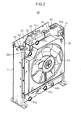
FIG. 2 is a perspective view illustrating a structure of the cooling apparatus when viewed from the side of a cooling fan. -
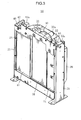
FIG. 3 is a perspective view illustrating the structure of the cooling apparatus when viewed from the side of a hear exchanger. -
FIG. 4 is a top plan view illustrating the structure of the cooling apparatus. -
FIG. 5 is a side sectional view illustrating the structure of the cooling apparatus. -
FIG. 6 is a front view illustrating a positional relationship between the heat exchanger and a projection of the cooling fan. -
FIG. 7 is a front view illustrating a positional relationship between a heat exchanger and a projection of a cooling fan in a cooling apparatus according to a second embodiment of the present invention. - With reference to the drawings, the present invention will now be described based on an embodiment thereof. The following preferred embodiments will be essentially described simply by way of illustration, but not intended to limit the present invention, or applicable objects or uses thereof.
-
FIG. 1 is a side view illustrating an overall structure of a constriction machine employing a cooling apparatus according to a first embodiment of the present invention. As illustrated inFIG. 1 , theconstruction machine 10 is a hydraulic shovel which comprises a crawler-type base carrier 1 and a swivel upper body 2 (body frame) rotatably mounted on thebase carrier 1. The swivelupper body 2 has abody frame 3 to which anattachment 4, acab 5, a machine room 6, acounterweight 7, etc., are attached. - In the first embodiment, a left side of the drawing sheet of
FIG. 1 , i.e., a side of theconstruction machine 10 at which theattachment 4 is disposed, will be referred to as "front (frontward)", and a front side with respect to the drawing sheet ofFIG. 1 , i.e., a side of theconstruction machine 10 toward which thecab 5 is disposed offset, will be referred to as "left (leftward)". In the following description, directions, such as frontward, rearward, rightward and leftward directions, will be followed by this definition, unless otherwise mentioned. - The
attachment 4 is supported by a front and central portion of the swivelupper body 2 in a vertically swingable manner. Theattachment 4 comprises a generally L-shaped boom 11 swingably supported by a pair of vertical plates (not illustrated) provided at approximately central positions of thebody frame 3, anarm 12 provided on a longitudinal plane of theboom 11 and swingably supported by theboom 11, and abucket 13 swingably supported by thearm 12. - The
cab 5 is a rectangular box-shaped operator's room which is internally equipped with an operator's seat, various control devices, various operating devices, etc., and disposed on a front and left side of the swivelupper body 2 so that it is located on a left side of and adjacent to theattachment 4. - The machine room 6 is provided to extend between right and left sides of a rear portion of the swivel
upper body 2. Thecounterweight 7 is provided to extend between right and left sides of a rear end of the swivelupper body 2. A left end of the machine room 6 is covered by abody cover 17. Thebody cover 17 has an air inlet opening 17a for taking outside air into the machine room 6. A right end of the machine room 6 has an air outlet opening (illustration is omitted) for discharging the intake air. - The machine room 6 is internally provided with a
cooling apparatus 20 according to a first embodiment of the present invention. As illustrated inFIGS. 2 to 5 , thecooling apparatus 20 comprises acooling fan 25, first tothird heat exchangers cooling fan 25 in an airflow direction, and ashroud 26 which covers an outer periphery of thecooling fan 25. - The
cooling fan 25 is adapted to suck outside air from the air inlet opening 17a and allow the sucked outside air to flow through the machine room 6 as cooling air. Cooling air sucked by thecooling fun 25 passes through the first tothird heat exchangers cooling fan 25 by theshroud 26, and, after cooling an engine, etc., discharged from the air outlet opening (illustration is omitted) to an outside of the machine room 6. - Each of the first to
third heat exchangers first heat exchanger 30, thesecond heat exchanger 40 and thethird heat exchanger 50 are formed as a radiator for cooling the engine, an oil cooler for cooling the operating oil, an intercooler for a turbocharger, respectively. - The
first heat exchanger 30 comprises acore 31, and upper andlower tanks core 31 so as to temporarily reserve engine coolant. Aninflow pipe 32a is connected to theupper tank 32 to allow the coolant to flow in theupper tank 32. Anoutflow pipe 33a is connected to thelower tank 33 to allow the coolant after being heat-exchanged with the cooling air in thecore 31 to flow out of thelower tank 33. - The
second heat exchanger 40 comprises acore 41, and upper andlower tanks core 41 so as to temporarily reserve operating oil. Aninflow pipe 42a is connected to theupper tank 42 to allow the operating oil to flow in theupper tank 42. Anoutflow pipe 43a is connected to thelower tank 43 to allow the operating oil after being heat-exchanged with the cooling air in thecore 41 to flow out of thelower tank 43. - The
third heat exchanger 50 comprises acore 51, and upper andlower tanks core 51 so as to temporarily reserve air compressed by a turbocharger (illustration is omitted). Aninflow pipe 52a is connected to theupper tank 52 to allow the compressed air to flow in theupper tank 52. Anoutflow pipe 53a is connected to thelower tank 53 to allow the air after being heat-exchanged with the cooling air in the core 51 to flow out of thelower tank 53. - The
respective cores third heat exchangers FIG. 6 , each of thecores third heat exchangers third heat exchangers core 31 of thefirst heat exchanger 30 disposed at a center of the first tothird heat exchangers - In other words, a height of each of the
cores third heat exchangers core 31 of thefirst heat exchanger 30 and an outer peripheral edge of a projection of the coolingfan 25 approximately coincides with a position of an upper end of a corresponding one of thecores third heat exchangers cores third heat exchangers fan 25. - Thus, it becomes possible to increase a ratio of a surface area of the
cores third heat exchangers fan 25, i.e., a region having a relatively large air volume, to the entire surface area of thecores cores - In the first embodiment, only heights of the first to
third heat exchangers third heat exchangers - The first to
third heat exchangers housing frames housing frame 21 comprises a pair of heightwise extending members each formed in a sectionally angular-C shape and disposed in widthwise spaced-apart relation. Thehousing frame 21 has a mountingbracket 22 attached between respective upper portions of the pair of members on an upstream side in the airflow direction (inFIG. 5 , on the left side). - The mounting
bracket 22 supports the respectiveupper tanks third heat exchangers third heat exchangers housing frame 21. Thus, the first tothird heat exchangers bracket 22. - The cooling
fan 25 is disposed downstream of thehousing frame 21 in the airflow direction. The outer periphery of the coolingfan 25 is covered by theshroud 26. Theshroud 26 is attached to thehousing frame 21. - A dust collecting filter (illustration is omitted) is provided between the
body cover 17 and each of the first tothird heat exchangers fan 25. - As above, in the
cooling apparatus 20 according to the first embodiment, no core is provided in a region out of the projection of the coolingfan 25, i.e., on an assumption that thecores third heat exchangers cores -
FIG. 7 is a front view illustrating a positional relationship between a heat exchanger and a projection of a cooling fan in a cooling apparatus according to a second embodiment of the present invention. The second embodiment is different from the first embodiment only in respective overall lengths of thecores - As illustrated in
FIG. 7 , each of thecores third heat exchangers third heat exchangers core 31 of thefirst heat exchanger 30 disposed at the center of the first tothird heat exchangers - In other words, the height of each of the
cores third heat exchangers core 31 of thefirst heat exchanger 30 and an outer peripheral edge of the projection of the coolingfan 25 approximately coincides with a position of an upper end of a corresponding one of the core 41, 51 of the second andthird heat exchangers core 31 of thefirst heat exchanger 30 and the outer peripheral edge of the projection of the coolingfan 25 approximately coincides with a position of a lower end of a corresponding one of the core 41, 51 of the second andthird heat exchangers cores third heat exchangers fan 25. - As above, in the second embodiment, no core is provided in a region out of the projection of the cooling
fan 25, i.e., on an assumption that thecores third heat exchangers cores third heat exchangers fan 25, i.e., a region having a relatively large air volume, to the entire surface area of thecores cores - Although the cooling
apparatuses 20 according to the first and second embodiment have been described based on a structure where the threeheat exchangers - Although the first and second embodiment have been described based on an example where the cooling apparatus of the present invention is applied to a hydraulic shovel, the cooling apparatus of the present invention can be widely applied to various types of construction machines, such as a demolition machine and a crushing machine.
- In summary, the present invention is directed to a cooling apparatus for a construction machine, which comprises at least three heat exchangers (a plural number of heat exchangers) arranged in widthwise side-by-side relation to each other, and a cooling fan disposed opposed to the plural number of heat exchangers, and characterized by the following features.
- In the present invention, each of the plural number of heat exchangers has a core (a portion of the heat exchanger where fluid within the heat exchanger is heat-exchanged with external cooling air), wherein each of the cores of the heat exchangers disposed at widthwise opposite ends of the plural number of heat exchangers is formed to have a height lower than that of the core of the heat exchanger disposed at a center of the plural number of heat exchangers, whereby a combination of the cores of the plural number of heat exchangers is formed in a shape corresponding to a projection of the cooling fan.
- In one aspect of the present invention, a combination of the cores of the plural number of heat exchangers is formed in a shape corresponding to a projection of the cooling fan. In other words, each of the cores of the heat exchangers disposed at the widthwise opposite ends of the plural number of heat exchangers is formed to have a height lower than that of the core of the heat exchanger disposed at the center of the plural number of heat exchangers.
- This structure makes it possible to optimize an air-volume distribution of cooling air passing through the cores of the plural number of heat exchangers arranged in side-by-side relation. Specifically, the cores have a rectangular shape, whereas the cooling fan has a circular shape. Thus, the air-volume distribution of cooling air passing through the cores concentrates in a region corresponding to the projection of the cooling fan, and the cooling air is less likely to flow through corners of the cores. In the present invention, the height of each of the cores of the heat exchangers disposed at the widthwise opposite ends is lowered so as to allow a combination of the cores of the plural number of heat exchangers to be formed in a shape corresponding to the projection of the cooling fan. Thus, it becomes possible to increase a ratio of a surface area of the cores occupied by the projection of the cooling fan, i.e., a region having a relatively large air volume, to the entire surface area of the cores, so as to optimize an air-volume distribution of cooling air passing through the cores. This makes it possible to improve cooling efficiency.
- Preferably, in the cooling apparatus of the present invention, each of the cores of the heat exchangers disposed at the widthwise opposite ends of the plural number of heat exchangers is formed in a shape where at least one of heightwise opposite ends of the core is sunk with respect to that of the core of the heat exchanger disposed at the center of the plural number of heat exchangers.
- According to this feature, upper and lower ends of each of the cores of the heat exchangers disposed at the widthwise opposite ends can be sunk with respect to the core of the heat exchanger disposed at the center, to further optimize the air-volume distribution of cooling air passing through the cores. In other words, no core is provided in a region out of the projection of the cooling fan, i.e., on an assumption that the cores of the plural number of heat exchangers are considered as a single integral core, no core is provided in a region corresponding to upper and lower corners of the integral core.
- In a specific preferred embodiment of the present invention, a height of an upper end of at least one of the cores of the heat exchangers disposed at the widthwise opposite ends of the plural number of heat exchangers is set such that a position of an intersecting point between a lateral edge of the core and an outer peripheral edge of the projection of the cooling fan approximately coincides with a position of the upper end of the core.
- More preferably, a height of an upper end of each of the cores of the two heat exchangers disposed at the widthwise opposite ends of the plural number of heat exchangers is set such that a position of an intersecting point between a lateral edge of each of the cores and an outer peripheral edge of the projection of the cooling fan approximately coincides with a position of the upper end of the core.
- According to the above feature, the height of the upper end of each of the cores of the heat exchangers disposed at the widthwise opposite ends is adjusted to approximately coincide with the intersecting point between the lateral edge of each of the cores and the outer peripheral edge of the projection of the cooling fan, so that it becomes possible to optimize the air-volume distribution of cooling air passing through the cores. In other words, a region out of the projection of the cooling fan can be reduced to, on an assumption that the cores of the plural number of heat exchangers are considered as a single integral core, effectively increase a ratio of a surface area of the integral core occupied by the projection of the cooling fan, i.e., a region having a relatively large air volume, to the entire surface area of the integral core.
- In another preferred embodiment of the present invention, a height of a lower end of at least one of the cores of the two heat exchangers disposed at the widthwise opposite ends is set such that the position of the intersecting point between the lateral edge of the core and the outer peripheral edge of the projection of the cooling fan approximately coincides with a position of the lower end of the core.
- More preferably, a height of a lower end of each of the cores of the two heat exchangers disposed at the widthwise opposite ends is set such that the position of the intersecting point between the lateral edge of each of the cores and the outer peripheral edge of the projection of the cooling fan approximately coincides with a position of the lower end of the core.
- According to the above feature, the height of the lower end of each of the cores of the heat exchangers disposed at the widthwise opposite ends is adjusted to approximately coincide with the intersecting point between the lateral edge of each of the cores and the outer peripheral edge of the projection of the cooling fan, so that it becomes possible to optimize the air-volume distribution of cooling air passing through the cores. In other words, a region out of the projection of the cooling fan can be reduced to, on an assumption that the cores of the plural number of heat exchangers are considered as a single integral core, effectively increase a ratio of a surface area of the integral core occupied by the projection of the cooling fan, i.e., a region having a relatively large air volume, to the entire surface area of the integral core.
- This application is based on Japanese Patent Application Serial No.
2011-050560 - Although the present invention has been fully described by way of example with reference to the accompanying drawings, it is to be understood that various changes and modifications will be apparent to those skilled in the art. Therefore, unless otherwise such changes and modifications depart from the scope of the present invention hereinafter defined, they should be construed as being included therein.
- The present invention is directed to a cooling apparatus comprising a plural number of (e.g., first to third) heat exchangers arranged in widthwise side-by-side relation to each other, and designed to optimize an air-volume distribution of cooling air passing through cores of the heat exchangers to thereby improve cooling efficiency. Each of the
cores third heat exchangers third heat exchangers core 31 of thefirst heat exchanger 30 disposed at a center of the first tothird heat exchangers cores third heat exchangers fan 25.
Claims (6)
- A cooling apparatus for a construction machine, comprising
a plural number of heat exchangers (30,40,50) arranged in widthwise side-by-side relation to each other, and
a cooling fan (25) disposed opposed to the plural number of heat exchangers,
wherein the plural number is at least three,
each of the plural number of heat exchangers has a core for performing heat exchange, and each of the cores (31,41,51) of the heat exchangers disposed at widthwise opposite ends of the plural number of heat exchangers is formed to have a height lower than that of the core of the heat exchanger disposed at a center of the plural number of heat exchangers, whereby a combination of the cores of the plural number of heat exchangers is formed in a shape corresponding to a projection of the cooling fan. - The cooling apparatus as defined in claim 1, wherein each of the cores (31,41,51) of the heat exchangers (30,40,50) disposed at the widthwise opposite ends of the plural number of heat exchangers is formed in a shape where at least one of heightwise opposite ends of the core is sunk with respect to that of the core (31) of the heat exchanger (30) disposed at the center of the plural number of heat exchangers.
- The cooling apparatus as defined in claim 2, wherein the height of at least one of the cores (41,51) of the heat exchangers (40,50) disposed at the widthwise opposite ends of the plural number of heat exchangers is set such that a position of an intersecting point between a lateral edge of the core and an outer peripheral edge of the projection of the cooling fan (25) approximately coincides with a position of an upper end of the core.
- The cooling apparatus as defined in claim 2, wherein the height of each of the cores (41,51) of the two heat exchangers (40,50) disposed at the widthwise opposite ends of the plural number of heat exchangers is set such that a position of an intersecting point between a lateral edge of each of the cores and an outer peripheral edge of the projection of the cooling fan approximately coincides with a position of an upper end of the core.
- The cooling apparatus as defined in claim 3, wherein a height of a lower end of at least one of the cores (41,51) of the two heat exchangers (40,50) disposed at the widthwise opposite ends is set such that the position of the intersecting point between the lateral edge of the core and the outer peripheral edge of the projection of the cooling fan (25) approximately coincides with a position of the lower end of the core.
- The cooling apparatus as defined in claim 4, wherein a height of a lower end of each of the cores (41,51) of the two heat exchangers (40,50) disposed at the widthwise opposite ends is set such that the position of the intersecting point between the lateral edge of each of the cores and the outer peripheral edge of the projection of the cooling fan (25) approximately coincides with a position of the lower end of the core.
Applications Claiming Priority (1)
| Application Number | Priority Date | Filing Date | Title |
|---|---|---|---|
| JP2011050560A JP5821221B2 (en) | 2011-03-08 | 2011-03-08 | Construction machine cooling system |
Publications (1)
| Publication Number | Publication Date |
|---|---|
| EP2527613A1 true EP2527613A1 (en) | 2012-11-28 |
Family
ID=45507429
Family Applications (1)
| Application Number | Title | Priority Date | Filing Date |
|---|---|---|---|
| EP12150232A Withdrawn EP2527613A1 (en) | 2011-03-08 | 2012-01-05 | Cooling apparatus for construction machine |
Country Status (4)
| Country | Link |
|---|---|
| US (1) | US9512773B2 (en) |
| EP (1) | EP2527613A1 (en) |
| JP (1) | JP5821221B2 (en) |
| CN (1) | CN102678259B (en) |
Families Citing this family (9)
| Publication number | Priority date | Publication date | Assignee | Title |
|---|---|---|---|---|
| JP5830110B2 (en) * | 2011-12-26 | 2015-12-09 | 日立建機株式会社 | Construction machinery |
| JP6040187B2 (en) * | 2014-02-24 | 2016-12-07 | 日立建機株式会社 | Construction machinery |
| BR102015026378A2 (en) * | 2014-10-21 | 2017-07-11 | Modine Manufacturing Company | COOLING MODULE WITH A TANK OF INTEGRATED COMPENSATION TO HIM |
| US9863122B2 (en) | 2016-03-31 | 2018-01-09 | Komatsu Ltd. | Cooling device and construction machine |
| JP6730766B2 (en) * | 2016-04-07 | 2020-07-29 | キャタピラー エス エー アール エル | Arrangement structure of cooling system in construction machinery |
| US10222130B2 (en) | 2016-08-08 | 2019-03-05 | Caterpillar Inc. | Work machine heat exchanger |
| JP7513395B2 (en) | 2016-08-26 | 2024-07-09 | イナーテック アイピー エルエルシー | Cooling system and method using single-phase fluid and flat-tube heat exchanger with countercurrent circulation - Patents.com |
| US20220307777A1 (en) * | 2021-03-23 | 2022-09-29 | Denso International America, Inc. | Heat exchanging system |
| KR102833516B1 (en) * | 2024-11-11 | 2025-07-15 | (주)코아팀즈 | Compact Composite Cooling Unit for Auxiliary Power Unit |
Citations (6)
| Publication number | Priority date | Publication date | Assignee | Title |
|---|---|---|---|---|
| JP2002021566A (en) * | 2000-07-12 | 2002-01-23 | Kobelco Contstruction Machinery Ltd | Cooler for construction machinery |
| US20030106502A1 (en) * | 2001-12-11 | 2003-06-12 | Penn Aubery W. | Engine cooling system |
| JP2005126990A (en) * | 2003-10-23 | 2005-05-19 | Hitachi Constr Mach Co Ltd | Cooling device of working machine |
| JP2005262970A (en) * | 2004-03-17 | 2005-09-29 | Hitachi Constr Mach Co Ltd | Construction machine |
| JP2010159691A (en) | 2009-01-08 | 2010-07-22 | Caterpillar Japan Ltd | Cooling device |
| JP2011050560A (en) | 2009-09-01 | 2011-03-17 | Kyoraku Sangyo Kk | Pachinko game machine |
Family Cites Families (8)
| Publication number | Priority date | Publication date | Assignee | Title |
|---|---|---|---|---|
| US4736727A (en) * | 1986-07-01 | 1988-04-12 | Navistar International Transportation Corp. | Highway truck with charge air cooling |
| JP3422036B2 (en) | 1992-07-13 | 2003-06-30 | 株式会社デンソー | Vehicle cooling system |
| US5373892A (en) * | 1993-10-04 | 1994-12-20 | Caterpillar Inc. | Dry sump lubricated internal combustion engine with modular cooling system |
| JP3903136B2 (en) * | 2001-11-05 | 2007-04-11 | 株式会社小松製作所 | Construction machine cooling system |
| DE10322211A1 (en) * | 2003-05-16 | 2004-12-02 | Modine Manufacturing Co., Racine | heat exchanger block |
| JP2005297801A (en) * | 2004-04-13 | 2005-10-27 | Denso Corp | Vehicle cooling system |
| US20110056668A1 (en) * | 2008-04-29 | 2011-03-10 | Carrier Corporation | Modular heat exchanger |
| JP5250497B2 (en) * | 2009-07-29 | 2013-07-31 | 日立建機株式会社 | Dust-proof net layout |
-
2011
- 2011-03-08 JP JP2011050560A patent/JP5821221B2/en not_active Expired - Fee Related
- 2011-12-30 US US13/340,965 patent/US9512773B2/en not_active Expired - Fee Related
-
2012
- 2012-01-05 EP EP12150232A patent/EP2527613A1/en not_active Withdrawn
- 2012-01-13 CN CN201210013202.0A patent/CN102678259B/en not_active Expired - Fee Related
Patent Citations (6)
| Publication number | Priority date | Publication date | Assignee | Title |
|---|---|---|---|---|
| JP2002021566A (en) * | 2000-07-12 | 2002-01-23 | Kobelco Contstruction Machinery Ltd | Cooler for construction machinery |
| US20030106502A1 (en) * | 2001-12-11 | 2003-06-12 | Penn Aubery W. | Engine cooling system |
| JP2005126990A (en) * | 2003-10-23 | 2005-05-19 | Hitachi Constr Mach Co Ltd | Cooling device of working machine |
| JP2005262970A (en) * | 2004-03-17 | 2005-09-29 | Hitachi Constr Mach Co Ltd | Construction machine |
| JP2010159691A (en) | 2009-01-08 | 2010-07-22 | Caterpillar Japan Ltd | Cooling device |
| JP2011050560A (en) | 2009-09-01 | 2011-03-17 | Kyoraku Sangyo Kk | Pachinko game machine |
Also Published As
| Publication number | Publication date |
|---|---|
| CN102678259A (en) | 2012-09-19 |
| JP5821221B2 (en) | 2015-11-24 |
| US9512773B2 (en) | 2016-12-06 |
| CN102678259B (en) | 2016-03-30 |
| JP2012188931A (en) | 2012-10-04 |
| US20120227943A1 (en) | 2012-09-13 |
Similar Documents
| Publication | Publication Date | Title |
|---|---|---|
| US9512773B2 (en) | Cooling apparatus for construction machine | |
| EP2295758B1 (en) | Installation structure for dustproof net | |
| EP2746087B1 (en) | Construction machine | |
| JP4450066B2 (en) | Vehicle front structure | |
| KR101896579B1 (en) | Construction machine | |
| JP5594197B2 (en) | Construction machine cooling structure | |
| CN104652518B (en) | Engineering machinery | |
| KR20000017383A (en) | Cooler for working vehicle | |
| EP2733342B1 (en) | Air filter arrangement for a work vehicle | |
| JP2023103214A (en) | construction machinery | |
| JP5363160B2 (en) | Construction equipment dustproof device | |
| JP2006052689A (en) | Construction machine cooling system | |
| JP2009228620A (en) | Cooling device | |
| JP4183584B2 (en) | Construction machine cooling system | |
| JP6730766B2 (en) | Arrangement structure of cooling system in construction machinery | |
| JP2005139952A (en) | Construction machine with air-cooled intercooler | |
| JP2009001187A (en) | Working vehicle | |
| JP2014173296A (en) | Construction machinery | |
| JP2016070001A (en) | Work machine | |
| CN105612292B (en) | Arrangement of components of a cooling unit in a construction machine | |
| CN220507322U (en) | Construction machinery condenser devices and construction machinery | |
| JP4915656B2 (en) | Wheel loader | |
| JP2007198031A (en) | Cooling system in construction machine | |
| JP2000081296A (en) | Heat exchanger for construction machine | |
| JP2005126990A (en) | Cooling device of working machine |
Legal Events
| Date | Code | Title | Description |
|---|---|---|---|
| PUAI | Public reference made under article 153(3) epc to a published international application that has entered the european phase |
Free format text: ORIGINAL CODE: 0009012 |
|
| AK | Designated contracting states |
Kind code of ref document: A1 Designated state(s): AL AT BE BG CH CY CZ DE DK EE ES FI FR GB GR HR HU IE IS IT LI LT LU LV MC MK MT NL NO PL PT RO RS SE SI SK SM TR |
|
| AX | Request for extension of the european patent |
Extension state: BA ME |
|
| 17P | Request for examination filed |
Effective date: 20130522 |
|
| 17Q | First examination report despatched |
Effective date: 20170130 |
|
| STAA | Information on the status of an ep patent application or granted ep patent |
Free format text: STATUS: THE APPLICATION IS DEEMED TO BE WITHDRAWN |
|
| 18D | Application deemed to be withdrawn |
Effective date: 20180103 |