JP2005297801A - Vehicle cooling system - Google Patents
Vehicle cooling system Download PDFInfo
- Publication number
- JP2005297801A JP2005297801A JP2004117932A JP2004117932A JP2005297801A JP 2005297801 A JP2005297801 A JP 2005297801A JP 2004117932 A JP2004117932 A JP 2004117932A JP 2004117932 A JP2004117932 A JP 2004117932A JP 2005297801 A JP2005297801 A JP 2005297801A
- Authority
- JP
- Japan
- Prior art keywords
- radiator
- core
- capacitor
- vehicle
- fan
- Prior art date
- Legal status (The legal status is an assumption and is not a legal conclusion. Google has not performed a legal analysis and makes no representation as to the accuracy of the status listed.)
- Pending
Links
Images


Classifications
-
- B—PERFORMING OPERATIONS; TRANSPORTING
- B60—VEHICLES IN GENERAL
- B60K—ARRANGEMENT OR MOUNTING OF PROPULSION UNITS OR OF TRANSMISSIONS IN VEHICLES; ARRANGEMENT OR MOUNTING OF PLURAL DIVERSE PRIME-MOVERS IN VEHICLES; AUXILIARY DRIVES FOR VEHICLES; INSTRUMENTATION OR DASHBOARDS FOR VEHICLES; ARRANGEMENTS IN CONNECTION WITH COOLING, AIR INTAKE, GAS EXHAUST OR FUEL SUPPLY OF PROPULSION UNITS IN VEHICLES
- B60K11/00—Arrangement in connection with cooling of propulsion units
- B60K11/02—Arrangement in connection with cooling of propulsion units with liquid cooling
- B60K11/04—Arrangement or mounting of radiators, radiator shutters, or radiator blinds
-
- F—MECHANICAL ENGINEERING; LIGHTING; HEATING; WEAPONS; BLASTING
- F01—MACHINES OR ENGINES IN GENERAL; ENGINE PLANTS IN GENERAL; STEAM ENGINES
- F01P—COOLING OF MACHINES OR ENGINES IN GENERAL; COOLING OF INTERNAL-COMBUSTION ENGINES
- F01P11/00—Component parts, details, or accessories not provided for in, or of interest apart from, groups F01P1/00 - F01P9/00
- F01P11/10—Guiding or ducting cooling-air, to, or from, liquid-to-air heat exchangers
-
- F—MECHANICAL ENGINEERING; LIGHTING; HEATING; WEAPONS; BLASTING
- F04—POSITIVE - DISPLACEMENT MACHINES FOR LIQUIDS; PUMPS FOR LIQUIDS OR ELASTIC FLUIDS
- F04D—NON-POSITIVE-DISPLACEMENT PUMPS
- F04D29/00—Details, component parts, or accessories
- F04D29/58—Cooling; Heating; Diminishing heat transfer
- F04D29/582—Cooling; Heating; Diminishing heat transfer specially adapted for elastic fluid pumps
-
- F—MECHANICAL ENGINEERING; LIGHTING; HEATING; WEAPONS; BLASTING
- F01—MACHINES OR ENGINES IN GENERAL; ENGINE PLANTS IN GENERAL; STEAM ENGINES
- F01P—COOLING OF MACHINES OR ENGINES IN GENERAL; COOLING OF INTERNAL-COMBUSTION ENGINES
- F01P3/00—Liquid cooling
- F01P3/18—Arrangements or mounting of liquid-to-air heat-exchangers
- F01P2003/182—Arrangements or mounting of liquid-to-air heat-exchangers with multiple heat-exchangers
-
- F—MECHANICAL ENGINEERING; LIGHTING; HEATING; WEAPONS; BLASTING
- F01—MACHINES OR ENGINES IN GENERAL; ENGINE PLANTS IN GENERAL; STEAM ENGINES
- F01P—COOLING OF MACHINES OR ENGINES IN GENERAL; COOLING OF INTERNAL-COMBUSTION ENGINES
- F01P5/00—Pumping cooling-air or liquid coolants
- F01P5/02—Pumping cooling-air; Arrangements of cooling-air pumps, e.g. fans or blowers
- F01P2005/025—Pumping cooling-air; Arrangements of cooling-air pumps, e.g. fans or blowers using two or more air pumps
-
- F—MECHANICAL ENGINEERING; LIGHTING; HEATING; WEAPONS; BLASTING
- F01—MACHINES OR ENGINES IN GENERAL; ENGINE PLANTS IN GENERAL; STEAM ENGINES
- F01P—COOLING OF MACHINES OR ENGINES IN GENERAL; COOLING OF INTERNAL-COMBUSTION ENGINES
- F01P2060/00—Cooling circuits using auxiliaries
- F01P2060/14—Condenser
-
- F—MECHANICAL ENGINEERING; LIGHTING; HEATING; WEAPONS; BLASTING
- F01—MACHINES OR ENGINES IN GENERAL; ENGINE PLANTS IN GENERAL; STEAM ENGINES
- F01P—COOLING OF MACHINES OR ENGINES IN GENERAL; COOLING OF INTERNAL-COMBUSTION ENGINES
- F01P5/00—Pumping cooling-air or liquid coolants
- F01P5/02—Pumping cooling-air; Arrangements of cooling-air pumps, e.g. fans or blowers
- F01P5/06—Guiding or ducting air to, or from, ducted fans
Landscapes
- Engineering & Computer Science (AREA)
- Mechanical Engineering (AREA)
- Chemical & Material Sciences (AREA)
- Combustion & Propulsion (AREA)
- General Engineering & Computer Science (AREA)
- Transportation (AREA)
- Physics & Mathematics (AREA)
- Thermal Sciences (AREA)
- Cooling, Air Intake And Gas Exhaust, And Fuel Tank Arrangements In Propulsion Units (AREA)
Abstract
【課題】 車両前方から見たときにファン31の一部がラジエータコア11の投影面から外れた位置にある車両用冷却装置において、ファン31により流通させる冷却空気を熱交換に有効に利用する。
【解決手段】 ラジエータコア11の投影面から外れた位置にあるファン31の前方部にコンデンサコア21を配置し、シュラウド4をラジエータコア11よりもコンデンサコア21側まで延長する。これにより、ファン31の一部がラジエータコア11の投影面から外れた位置にあっても、ファン31により流通させる冷却空気はコンデンサコア21およびラジエータコア11の少なくとも一方を通過するため、ファン31により流通させる冷却空気が熱交換に有効に利用される。
【選択図】 図3
PROBLEM TO BE SOLVED: To effectively use cooling air circulated by a fan 31 for heat exchange in a vehicular cooling device in which a part of a fan 31 is located away from a projection surface of a radiator core 11 when viewed from the front of the vehicle.
A condenser core 21 is disposed in front of a fan 31 at a position off the projection surface of the radiator core 11, and a shroud 4 is extended from the radiator core 11 to the condenser core 21 side. Thereby, even if a part of the fan 31 is located at a position away from the projection surface of the radiator core 11, the cooling air circulated by the fan 31 passes through at least one of the condenser core 21 and the radiator core 11. The cooling air to be circulated is effectively used for heat exchange.
[Selection] Figure 3
Description
本発明は、冷媒を冷却するコンデンサ、エンジン冷却水を冷却するラジエータ、および冷却空気を流通させるファンを有する車両用冷却装置に関するものである。 The present invention relates to a vehicular cooling device having a condenser for cooling refrigerant, a radiator for cooling engine cooling water, and a fan for circulating cooling air.
従来、自動車のラジエータとファンのレイアウトは、車両前方から見たときにラジエータコアの投影面内にファンの外径を収めるのが一般的である(例えば、特許文献1、2参照)。以下、本明細書では、車両前方から見たときの投影面を、単に投影面という。
しかしながら、より多くの風量を得るために大径ファンを設置した場合など、ファンの一部がラジエータコアの投影面から外れるレイアウトもある。この場合は、ラジエータコアの投影面から外れた部分は、直接ラジエータコアから空気を吸うことができない。換言すると、ファンにより流通させる冷却空気の一部はラジエータコアを通過しない。したがって、ファンにより流通させる冷却空気の一部が熱交換に利用されないという問題があった。 However, there is a layout in which a part of the fan deviates from the projection surface of the radiator core, such as when a large-diameter fan is installed to obtain a larger air volume. In this case, the portion of the radiator core that is out of the projection plane cannot directly suck air from the radiator core. In other words, a part of the cooling air circulated by the fan does not pass through the radiator core. Therefore, there is a problem that part of the cooling air circulated by the fan is not used for heat exchange.
本発明は上記点に鑑みて、熱交換に利用されていなかった冷却空気を熱交換に利用可能にすることを目的とする。 In view of the above points, an object of the present invention is to enable cooling air that has not been used for heat exchange to be used for heat exchange.
上記目的を達成するため、請求項1に記載の発明では、冷凍サイクル内を循環する冷媒を冷却するコンデンサコア(21)を有するコンデンサ(2)と、コンデンサ(2)よりも車両後方側に配置され、エンジン冷却水を冷却するラジエータコア(11)を有するラジエータ(1)と、ラジエータ(1)よりも車両後方側に配置され、コンデンサ(2)およびラジエータ(1)に冷却空気を流通させるファン(31)と、ラジエータ(1)からファン(31)に至る空気通路を形成するシュラウド(4)とを備え、車両前方から見たときにファン(31)の一部がラジエータコア(11)の投影面から外れた位置にある車両用冷却装置において、コンデンサコア(21)は、ラジエータコア(11)の投影面から外れた位置にあるファン(31)の前方部に配置され、シュラウド(4)は、ラジエータコア(11)よりもコンデンサコア(21)側まで延長されていることを特徴とする。 In order to achieve the above object, according to the first aspect of the present invention, the condenser (2) having the condenser core (21) for cooling the refrigerant circulating in the refrigeration cycle is disposed on the vehicle rear side with respect to the condenser (2). And a radiator (1) having a radiator core (11) for cooling engine cooling water, and a fan that is disposed on the vehicle rear side of the radiator (1) and distributes cooling air to the condenser (2) and the radiator (1) (31) and a shroud (4) that forms an air passage from the radiator (1) to the fan (31), and when viewed from the front of the vehicle, a part of the fan (31) is attached to the radiator core (11). In the vehicular cooling device located at a position away from the projection surface, the condenser core (21) is provided with a fan (3) located away from the projection surface of the radiator core (11). ) Is disposed in front of the shroud (4) is characterized in that it is extended to the condenser core (21) side of the radiator core (11).
これによると、ファンの一部がラジエータコアの投影面から外れた位置にあっても、ファンにより流通させる冷却空気はコンデンサコアおよびラジエータコアの少なくとも一方を通過するため、ファンにより流通させる冷却空気が熱交換に有効に利用される。 According to this, even if a part of the fan is located away from the projection surface of the radiator core, the cooling air circulated by the fan passes through at least one of the condenser core and the radiator core. Effectively used for heat exchange.
また、コンデンサコアにおいて、ラジエータコアの投影面から外れた位置にあるファンの前方部に位置する部位では、通風抵抗が小さいため通過風速が増加し、風量が増加して、熱交換効率がアップする。 Further, in the condenser core, the portion located in the front part of the fan that is located away from the projection surface of the radiator core increases the passing air speed because the ventilation resistance is small, the air volume increases, and the heat exchange efficiency is increased. .
請求項2に記載の発明のように、ラジエータコア(11)の上下方向寸法および車両左右方向寸法のうち小さい方の寸法よりも、ファン(31)の外形寸法が大きい場合に好適である。 As in the second aspect of the invention, the fan (31) is suitable when the outer dimension is larger than the smaller one of the vertical dimension of the radiator core (11) and the horizontal dimension of the vehicle.
すなわち、ファンを電動機で駆動する形式の冷却装置において風量を増加させるには、ファンを大きくするかまたは電動機の能力をアップする方法があり、コスト面を考慮してファンを大きくするのが一般的である。そして、ファンを大きくした結果請求項2のような構成になってファンの一部がラジエータコアの投影面から外れても、ファンにより流通させる冷却空気を熱交換に有効に利用することができる。
That is, in order to increase the air volume in a cooling device of a type in which the fan is driven by an electric motor, there is a method of increasing the fan or increasing the capacity of the electric motor, and the fan is generally increased in consideration of cost. It is. As a result of enlarging the fan, the cooling air circulated by the fan can be effectively used for heat exchange even if a part of the fan comes off the projection surface of the radiator core due to the configuration as in
請求項3に記載の発明では、冷媒はコンデンサコア(21)内を車両左右方向に流れ、エンジン冷却水はラジエータコア(11)内を上下方向に流れることを特徴とする。
The invention according to
これによると、コンデンサコアの投影面外にラジエータのタンクを位置させるとともに、ラジエータコアの投影面外にコンデンサのタンクを位置させることができる。 According to this, the tank of the radiator can be positioned outside the projection surface of the capacitor core, and the tank of the capacitor can be positioned outside the projection surface of the radiator core.
したがって、タンクは通風抵抗にならないため風量低下を防止することができ、また、コンデンサコアとラジエータのタンクとの干渉およびラジエータコアとコンデンサのタンクとの干渉がないため、コンデンサコアとラジエータコアを近接して配置することができ、冷却装置の車両前後方向寸法を小さくすることができる。 Therefore, since the tank does not provide ventilation resistance, it is possible to prevent a decrease in the air volume, and since there is no interference between the condenser core and the radiator tank and between the radiator core and the condenser tank, the condenser core and the radiator core are close to each other. The size of the cooling device in the vehicle front-rear direction can be reduced.
請求項4に記載の発明では、ラジエータ(1)は、ラジエータコア(11)の両端にラジエータタンク(13、14)を備え、シュラウド(4)は、ラジエータタンク(13、14)が配置された側では、ラジエータコア(11)における車両後方側の面(111)に対向する位置まで延長されていることを特徴とする。
In the invention according to
これによると、シュラウドとラジエータタンクとの干渉を避けつつ、ファンにより流通させる冷却空気をコンデンサコアまたはラジエータコアに確実に導くことができる。 According to this, the cooling air circulated by the fan can be reliably guided to the condenser core or the radiator core while avoiding interference between the shroud and the radiator tank.
請求項5に記載の発明では、コンデンサ(2)は、コンデンサコア(21)の両端にコンデンサタンク(22、25)を備え、シュラウド(4)は、コンデンサタンク(22、25)が配置された側では、コンデンサコア(21)における車両後方側の面(211)に対向する位置まで延長されていることを特徴とする。 In the invention according to claim 5, the capacitor (2) includes capacitor tanks (22, 25) at both ends of the capacitor core (21), and the capacitor tank (22, 25) is disposed in the shroud (4). On the side, the capacitor core (21) is extended to a position facing the vehicle rear surface (211).
これによると、シュラウドとコンデンサタンクとの干渉を避けつつ、ファンにより流通させる冷却空気をコンデンサコアまたはラジエータコアに確実に導くことができる。 According to this, it is possible to reliably guide the cooling air circulated by the fan to the condenser core or the radiator core while avoiding interference between the shroud and the condenser tank.
請求項6に記載の発明では、ラジエータ(1)は、ラジエータコア(11)の両端にラジエータタンク(13、14)を備え、コンデンサ(2)は、コンデンサコア(21)の両端にコンデンサタンク(22、25)を備え、シュラウド(4)は、ラジエータタンク(13、14)およびコンデンサタンク(22、25)が配置されていない側では、コンデンサコア(21)における車両後方側の面(211)よりも車両前方側まで延長されていることを特徴とする。 In the invention according to claim 6, the radiator (1) includes the radiator tanks (13, 14) at both ends of the radiator core (11), and the capacitor (2) has a capacitor tank ( 22 and 25), and the shroud (4) has a rear surface (211) of the capacitor core (21) on the side where the radiator tank (13, 14) and the capacitor tank (22, 25) are not disposed. It is further extended to the vehicle front side.
これによると、ファンにより流通させる冷却空気をコンデンサコアまたはラジエータコアに確実に導くことができる。 According to this, the cooling air circulated by the fan can be reliably guided to the condenser core or the radiator core.
なお、上記各手段の括弧内の符号は、後述する実施形態に記載の具体的手段との対応関係を示すものである。 In addition, the code | symbol in the bracket | parenthesis of each said means shows the correspondence with the specific means as described in embodiment mentioned later.
(第1実施形態)
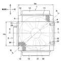
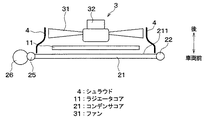
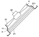
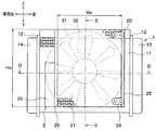
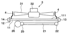
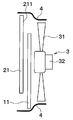
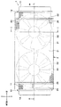
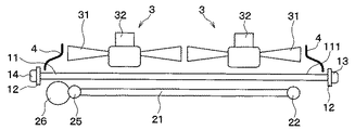
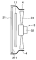
本発明の第1実施形態について説明する。図1は第1実施形態に係る冷却装置を車両前方から見た正面図、図2は図1のコンデンサを取り外した状態の正面図、図3は図1のA−A線に沿う断面図、図4は図1のB−B線に沿う断面図である。
(First embodiment)
A first embodiment of the present invention will be described. 1 is a front view of the cooling device according to the first embodiment as viewed from the front of the vehicle, FIG. 2 is a front view of the state in which the capacitor of FIG. 1 is removed, and FIG. 3 is a cross-sectional view taken along line AA of FIG. 4 is a cross-sectional view taken along line BB in FIG.
図1〜図4に示すように、冷却装置は、車両の走行用エンジン(図示せず)の冷却水を冷却するラジエータ1、冷凍サイクル(図示せず)内を循環する冷媒を冷却凝縮させるコンデンサ2、ラジエータ1およびコンデンサ2に冷却空気を流通させる送風機3、送風機3により流通させる冷却空気の通路を形成するシュラウド4を備えている。
As shown in FIGS. 1 to 4, the cooling device includes a
冷却装置は、車両のエンジンルーム内における車両前方側に搭載される。そして、コンデンサ2が最も車両前方側に位置し、コンデンサ2よりも車両後方側にラジエータ1が配置され、ラジエータ1よりも車両後方側に送風機3が配置されている。
The cooling device is mounted on the vehicle front side in the engine room of the vehicle. And the capacitor |
ラジエータ1は、多数のチューブと多数のフィンを有する周知の構成のラジエータコア11を備えている。このラジエータコア11は、矩形状であり、チューブ内を流通するエンジン冷却水とチューブの外を流通する空気とを熱交換させてエンジン冷却水を冷却する。
The
ラジエータコア11の上下端には、ラジエータコア11の補強部材をなすコアプレート12がろう付けされている。ラジエータコア11の上端には、ラジエータコア11の各チューブにエンジン冷却水を分配するラジエータ入口タンク13を備え、ラジエータコア11の下端には、ラジエータコア11の各チューブからのエンジン冷却水を集合させるラジエータ出口タンク14を備えている。したがって、このラジエータ1は、ラジエータコア11においてエンジン冷却水が上から下に流れる、いわゆるダウンフロータイプである。このラジエータ1は、アルミニウム製である。なお、ラジエータ入口タンク13およびラジエータ出口タンク14は、本発明のラジエータタンクに相当する。
A
コンデンサ2は、多数のチューブと多数のフィンを有する周知の構成のコンデンサコア21を備えている。このコンデンサコア21は、矩形状であり、チューブ内を流通する冷媒とチューブの外を流通する空気とを熱交換させて冷媒を冷却する。
The
コンデンサコア21の車両左端側には、コンデンサコア21の各チューブと連通するコンデンサ第1タンク22を備え、コンデンサ第1タンク22の上端近傍には、コンデンサ2への冷媒の入口となる入口ジョイント23が配置され、コンデンサ第1タンク22の下端近傍には、コンデンサ2からの冷媒の出口となる出口ジョイント24が配置されている。
A capacitor
コンデンサコア21の車両右端側には、コンデンサコア21の各チューブと連通するコンデンサ第2タンク25を備え、コンデンサ第2タンク25には、冷媒の気液を分離して液冷媒を蓄えるモジュレータ26が接合されている。コンデンサ2は、アルミニウム製である。なお、コンデンサ第1タンク22およびコンデンサ第2タンク25は、本発明のコンデンサタンクに相当する。
A capacitor
コンデンサ2は、入口ジョイント23から気相冷媒が流入するようになっており、その気相冷媒は、コンデンサ第1タンク22における上部空間を通って、コンデンサコア21における上方側のチューブ内を車両左側から車両右側に向かって流れ、このときに気相冷媒を冷却空気と熱交換させて、冷却、凝縮させる。
The
冷却された冷媒は、コンデンサ第2タンク25における上部空間を通ってモジュレータ26に流入する。モジュレータ26内部において気液分離された冷媒のうち液冷媒は、コンデンサ第2タンク25における下部空間を通って、コンデンサコア21における下方側のチューブ内を車両右側から車両左側に向かって流れ、このときに液冷媒を冷却空気と熱交換させて過冷却する。
The cooled refrigerant flows into the
過冷却された冷媒は、コンデンサ第1タンク22における下部空間を通って、出口ジョイント24からコンデンサ2外へ流出するようになっている。
The supercooled refrigerant flows out of the
送風機3は、空気流を発生させるファン31と、ファン31を駆動する電動機32とを有する。ファン31は、放射状に配置された複数のブレードを有し、回転軸方向の空気流を発生させるものであり、いわゆる軸流ファンである。
The
ここで、ラジエータコア11の上下方向寸法をラジエータコア高さHr、ラジエータコア11の車両左右方向寸法をラジエータコア幅Wr、コンデンサコア21の上下方向寸法をコンデンサコア高さHc、コンデンサコア21の車両左右方向寸法をコンデンサコア幅Wc、ファン31の外形寸法をファン径φDとすると、Hr>φD>Wr、Wc>φD>Hc、の関係になっている。
Here, the vertical dimension of the
ファン径φDがラジエータコア幅Wよりも大であるため、特に図2から明らかなように、ラジエータコア11の車両左右方向両側で、ファン31の一部がラジエータコア11の投影面から外れている。そして、コンデンサコア21は、ラジエータコア11の投影面から外れた位置にあるファン31の前方部に配置されている。換言すると、ラジエータコア11の投影面から外れた位置にあるファン31の部位は、車両前方から見た状態ではコンデンサコア21によって覆われている。
Since the fan diameter φD is larger than the radiator core width W, as is apparent from FIG. 2 in particular, a part of the
また、特に図1から明らかなように、コンデンサコア21の投影面外に、コアプレート12、ラジエータ入口タンク13、およびラジエータ出口タンク14を位置させている。一方、ラジエータコア11の投影面外に、コンデンサ第1タンク22、入口ジョイント23、出口ジョイント24、コンデンサ第2タンク25、およびモジュレータ26を位置させている。
Further, as is clear from FIG. 1 in particular, the
シュラウド4は、樹脂製であり、前述した冷却空気の通路を形成するとともに、電動機32を保持している。また、シュラウド4は、車両前方から見た状態では外形形状は4角形であり、シュラウド4の車両左右方向寸法はコンデンサコア幅Wcと略等しく、シュラウド4の上下方向寸法はラジエータコア高さHrと略等しくなっている。
The
シュラウド4は、ラジエータコア11よりもコンデンサコア21側まで延長されている。より詳細には、図3に示すように、シュラウド4における車両左右方向両端部、すなわち、コンデンサ第1タンク22やコンデンサ第2タンク25が配置された側では、コンデンサコア21における車両後方側のコンデンサコア後方面211の近傍までシュラウド4が延長されて、シュラウド4における車両前方側の端部がコンデンサコア後方面211に対向している。また、図4に示すように、コンデンサ第1タンク22やコンデンサ第2タンク25が配置されていない部位で、且つラジエータコア11が位置していない部位では、シュラウド4はコンデンサコア後方面211よりも車両前方側まで延長されている。
The
上記実施形態では、シュラウド4をラジエータコア11よりもコンデンサコア21側まで延長しているため、ファン31の一部がラジエータコア11の投影面から外れた位置にあっても、ファン31により流通させる冷却空気はコンデンサコア21およびラジエータコア11の少なくとも一方を通過し、ファン31により流通させる冷却空気が熱交換に有効に利用される。
In the above embodiment, the
また、コンデンサコア21において、ラジエータコア11の投影面から外れた位置にあるファン31の前方部に位置する部位では、通風抵抗が小さいため通過風速が増加し、風量が増加して、熱交換効率がアップする。
Further, in the
また、冷媒はコンデンサコア21内を車両左右方向に流れ、エンジン冷却水はラジエータコア11内を上下方向に流れるようにしているため、コンデンサコア21の投影面外に、コアプレート12、ラジエータ入口タンク13、およびラジエータ出口タンク14を位置させるとともに、ラジエータコア11の投影面外に、コンデンサ第1タンク22、入口ジョイント23、出口ジョイント24、コンデンサ第2タンク25、およびモジュレータ26を位置させることができる。
Further, since the refrigerant flows in the left-right direction of the vehicle in the
これにより、タンク等は通風抵抗にならないため風量低下を防止することができ、また、コンデンサコア21とラジエータ1のタンク等との干渉およびラジエータコア21とコンデンサ2のタンク等との干渉がないため、コンデンサコア21とラジエータコア11を近接して配置することができ、冷却装置の車両前後方向寸法を小さくすることができる。
As a result, since the tank or the like does not become a ventilation resistance, a decrease in the air volume can be prevented, and there is no interference between the
(第2実施形態)
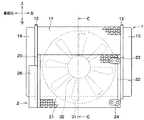
本発明の第2実施形態について説明する。図5は第2実施形態に係る冷却装置を車両前方から見た正面図、図6は図5のC−C線に沿う断面図である。なお、第1実施形態と同一もしくは均等部分には同一の符号を付し、その説明を省略する。
(Second Embodiment)
A second embodiment of the present invention will be described. FIG. 5 is a front view of the cooling device according to the second embodiment viewed from the front of the vehicle, and FIG. 6 is a cross-sectional view taken along the line CC of FIG. In addition, the same code | symbol is attached | subjected to the same or equivalent part as 1st Embodiment, and the description is abbreviate | omitted.
第1実施形態では、エンジン冷却水がラジエータコア11内を上下方向に流れるダウンフロータイプのラジエータ1を用いたが、本実施形態では、エンジン冷却水がラジエータコア11内を車両左右方向に流れるクロスフロータイプのラジエータ1を用いている。
In the first embodiment, the
図5に示すように、本実施形態のラジエータ1は、ラジエータコア11の車両左右両端にコアプレート12がろう付けされ、ラジエータコア11の車両左端側にラジエータ入口タンク13が配置され、ラジエータコア11の車両右端側にラジエータ出口タンク14が配置されている。
As shown in FIG. 5, in the
そして、ラジエータコア11の下方側で、ファン31の一部がラジエータコア11の投影面から外れており、ラジエータコア11の投影面から外れた位置にあるファン31の部位は、車両前方から見た状態ではコンデンサコア21によって覆われている。
Further, on the lower side of the
図6に示すように、シュラウド4における上端部および下端部、すなわち、ラジエータ入口タンク13、ラジエータ出口タンク14、コンデンサ第1タンク22、およびコンデンサ第2タンク25が配置されていない側では、シュラウド4はコンデンサコア後方面211よりも車両前方側まで延長されている。
As shown in FIG. 6, the
(第3実施形態)
本発明の第3実施形態について説明する。図7は第3実施形態に係る冷却装置を車両前方から見た正面図、図8は図7のD−D線に沿う断面図、図9は図7のE−E線に沿う断面図である。なお、第1実施形態と同一もしくは均等部分には同一の符号を付し、その説明を省略する。
(Third embodiment)
A third embodiment of the present invention will be described. 7 is a front view of the cooling device according to the third embodiment as viewed from the front of the vehicle, FIG. 8 is a cross-sectional view taken along line DD in FIG. 7, and FIG. 9 is a cross-sectional view taken along line EE in FIG. is there. In addition, the same code | symbol is attached | subjected to the same or equivalent part as 1st Embodiment, and the description is abbreviate | omitted.
本実施形態は、図7に示すように、クロスフロータイプのラジエータ1を用いるとともに、コンデンサコア21が縦長(Hc>Wc)のコンデンサ2を用いている。また、ラジエータコア11の上方側で、ファン31の一部がラジエータコア11の投影面から外れており、ラジエータコア11の投影面から外れた位置にあるファン31の部位は、車両前方から見た状態ではコンデンサコア21によって覆われている。
In the present embodiment, as shown in FIG. 7, a cross
図8に示すように、シュラウド4における車両左右方向両端部、すなわち、ラジエータ入口タンク13やラジエータ出口タンク14が配置された側では、ラジエータコア11における車両後方側のラジエータコア後方面111の近傍までシュラウド4が延長されて、シュラウド4における車両前方側の端部がラジエータコア後方面111に対向している。
As shown in FIG. 8, in the left and right ends of the vehicle in the
一方、図9に示すように、シュラウド4における上端部および下端部、すなわち、ラジエータ入口タンク13、ラジエータ出口タンク14、コンデンサ第1タンク22、およびコンデンサ第2タンク25が配置されていない側では、シュラウド4はコンデンサコア後方面211よりも車両前方側まで延長されている。
On the other hand, as shown in FIG. 9, the upper and lower ends of the
(第4実施形態)
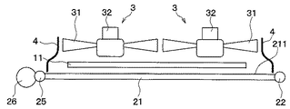
本発明の第4実施形態について説明する。図10は第4実施形態に係る冷却装置を車両前方から見た正面図、図11は図10のF−F線に沿う断面図、図12は図10のG−G線に沿う断面図である。なお、第1実施形態と同一もしくは均等部分には同一の符号を付し、その説明を省略する。
(Fourth embodiment)
A fourth embodiment of the present invention will be described. 10 is a front view of the cooling device according to the fourth embodiment as viewed from the front of the vehicle, FIG. 11 is a cross-sectional view taken along line FF in FIG. 10, and FIG. 12 is a cross-sectional view taken along line GG in FIG. is there. In addition, the same code | symbol is attached | subjected to the same or equivalent part as 1st Embodiment, and the description is abbreviate | omitted.
本実施形態は、図10に示すように、2台の送風機3を車両左右方向に配置している。また、ラジエータコア11の車両左右方向両側で、ファン31の一部がラジエータコア11の投影面から外れており、ラジエータコア11の投影面から外れた位置にあるファン31の部位は、車両前方から見た状態ではコンデンサコア21によって覆われている。
In the present embodiment, as shown in FIG. 10, the two
図11に示すように、シュラウド4における車両左右方向両端部、すなわち、すなわち、コンデンサ第1タンク22やコンデンサ第2タンク25が配置された側では、コンデンサコア後方面211の近傍までシュラウド4が延長されて、シュラウド4における車両前方側の端部がコンデンサコア後方面211に対向している。
As shown in FIG. 11, the
一方、図12に示すように、シュラウド4における上端部および下端部、すなわち、ラジエータ入口タンク13やラジエータ出口タンク14が配置された側では、ラジエータコア後方面111の近傍までシュラウド4が延長されて、シュラウド4における車両前方側の端部がラジエータコア後方面111に対向している。
On the other hand, as shown in FIG. 12, the
(第5実施形態)
本発明の第5実施形態について説明する。図13は第5実施形態に係る冷却装置を車両前方から見た正面図、図14は図13のH−H線に沿う断面図、図15は図13のI−IG線に沿う断面図である。なお、第1実施形態と同一もしくは均等部分には同一の符号を付し、その説明を省略する。
(Fifth embodiment)
A fifth embodiment of the present invention will be described. 13 is a front view of the cooling device according to the fifth embodiment viewed from the front of the vehicle, FIG. 14 is a cross-sectional view taken along line H-H in FIG. 13, and FIG. 15 is a cross-sectional view taken along line I-IG in FIG. is there. In addition, the same code | symbol is attached | subjected to the same or equivalent part as 1st Embodiment, and the description is abbreviate | omitted.
本実施形態は、図13に示すように、2台の送風機3を車両左右方向に配置するとともに、クロスフロータイプのコンデンサ2を用いている。また、ラジエータコア11の上方側で、ファン31の一部がラジエータコア11の投影面から外れており、ラジエータコア11の投影面から外れた位置にあるファン31の部位は、車両前方から見た状態ではコンデンサコア21によって覆われている。
In this embodiment, as shown in FIG. 13, two
図14に示すように、シュラウド4における車両左右方向両端部、すなわち、ラジエータ入口タンク13やラジエータ出口タンク14が配置された側では、ラジエータコア後方面111の近傍までシュラウド4が延長されて、シュラウド4における車両前方側の端部がラジエータコア後方面111に対向している。
As shown in FIG. 14, the
一方、図15に示すように、シュラウド4における上端部および下端部、すなわち、ラジエータ入口タンク13、ラジエータ出口タンク14、コンデンサ第1タンク22、およびコンデンサ第2タンク25が配置されていない側では、シュラウド4はコンデンサコア後方面211よりも車両前方側まで延長されている。
On the other hand, as shown in FIG. 15, the upper and lower ends of the
(他の実施形態)
上記各実施形態の冷却装置は、車両のボディに一体に設けられた取り付けパネルに装着される構成であってもよいし、あるいは、冷却装置を車両のボディに取り付けるためのラジエータサポート部材と一体化した構成でもよい。
(Other embodiments)
The cooling device of each of the above embodiments may be configured to be mounted on a mounting panel provided integrally with the vehicle body, or may be integrated with a radiator support member for mounting the cooling device to the vehicle body. The configuration may be also possible.
1…ラジエータ、2…コンデンサ、4…シュラウド、11…ラジエータコア、21…コンデンサコア、31…ファン。
DESCRIPTION OF
Claims (6)
前記コンデンサ(2)よりも車両後方側に配置され、エンジン冷却水を冷却するラジエータコア(11)を有するラジエータ(1)と、
前記ラジエータ(1)よりも車両後方側に配置され、前記コンデンサ(2)および前記ラジエータ(1)に冷却空気を流通させるファン(31)と、
前記ラジエータ(1)から前記ファン(31)に至る空気通路を形成するシュラウド(4)とを備え、
車両前方から見たときに前記ファン(31)の一部が前記ラジエータコア(11)の投影面から外れた位置にある車両用冷却装置において、
前記コンデンサコア(21)は、前記ラジエータコア(11)の投影面から外れた位置にある前記ファン(31)の前方部に配置され、
前記シュラウド(4)は、前記ラジエータコア(11)よりも前記コンデンサコア(21)側まで延長されていることを特徴とする車両用冷却装置。 A condenser (2) having a condenser core (21) for cooling the refrigerant circulating in the refrigeration cycle;
A radiator (1) disposed on the vehicle rear side of the condenser (2) and having a radiator core (11) for cooling engine coolant;
A fan (31) that is disposed on the vehicle rear side of the radiator (1) and that circulates cooling air to the condenser (2) and the radiator (1);
A shroud (4) forming an air passage from the radiator (1) to the fan (31),
In the vehicular cooling device in which a part of the fan (31) is out of the projection surface of the radiator core (11) when viewed from the front of the vehicle,
The capacitor core (21) is disposed at a front portion of the fan (31) at a position deviated from the projection plane of the radiator core (11),
The vehicle shroud (4), wherein the shroud (4) extends from the radiator core (11) to the condenser core (21).
前記シュラウド(4)は、前記ラジエータタンク(13、14)が配置された側では、前記ラジエータコア(11)における車両後方側の面(111)に対向する位置まで延長されていることを特徴とする請求項1ないし3のいずれか1つに記載の車両用冷却装置。 The radiator (1) includes radiator tanks (13, 14) at both ends of the radiator core (11).
The shroud (4) is extended to a position facing the rear surface (111) of the radiator core (11) on the side where the radiator tank (13, 14) is disposed. The vehicle cooling device according to any one of claims 1 to 3.
前記シュラウド(4)は、前記コンデンサタンク(22、25)が配置された側では、前記コンデンサコア(21)における車両後方側の面(211)に対向する位置まで延長されていることを特徴とする請求項1ないし3のいずれか1つに記載の車両用冷却装置。 The capacitor (2) includes capacitor tanks (22, 25) at both ends of the capacitor core (21).
The shroud (4) is extended to a position facing the rear surface (211) of the capacitor core (21) on the side where the capacitor tank (22, 25) is disposed. The vehicle cooling device according to any one of claims 1 to 3.
前記コンデンサ(2)は、前記コンデンサコア(21)の両端にコンデンサタンク(22、25)を備え、
前記シュラウド(4)は、前記ラジエータタンク(13、14)および前記コンデンサタンク(22、25)が配置されていない側では、前記コンデンサコア(21)における車両後方側の面(211)よりも車両前方側まで延長されていることを特徴とする請求項1ないし3のいずれか1つに記載の車両用冷却装置。 The radiator (1) includes radiator tanks (13, 14) at both ends of the radiator core (11).
The capacitor (2) includes capacitor tanks (22, 25) at both ends of the capacitor core (21).
The shroud (4) is located on the side where the radiator tanks (13, 14) and the capacitor tanks (22, 25) are not disposed, rather than the vehicle rear side surface (211) of the capacitor core (21). The vehicular cooling device according to any one of claims 1 to 3, wherein the vehicular cooling device is extended to a front side.
Priority Applications (2)
| Application Number | Priority Date | Filing Date | Title |
|---|---|---|---|
| JP2004117932A JP2005297801A (en) | 2004-04-13 | 2004-04-13 | Vehicle cooling system |
| DE200510016842 DE102005016842A1 (en) | 2004-04-13 | 2005-04-12 | Cooling device for radiator of motor vehicle has shroud extended to side of condenser core arranged at front portion of fan rather than to radiator core arranged at rear side of vehicle body |
Applications Claiming Priority (1)
| Application Number | Priority Date | Filing Date | Title |
|---|---|---|---|
| JP2004117932A JP2005297801A (en) | 2004-04-13 | 2004-04-13 | Vehicle cooling system |
Publications (1)
| Publication Number | Publication Date |
|---|---|
| JP2005297801A true JP2005297801A (en) | 2005-10-27 |
Family
ID=35220115
Family Applications (1)
| Application Number | Title | Priority Date | Filing Date |
|---|---|---|---|
| JP2004117932A Pending JP2005297801A (en) | 2004-04-13 | 2004-04-13 | Vehicle cooling system |
Country Status (2)
| Country | Link |
|---|---|
| JP (1) | JP2005297801A (en) |
| DE (1) | DE102005016842A1 (en) |
Cited By (1)
| Publication number | Priority date | Publication date | Assignee | Title |
|---|---|---|---|---|
| JP2012188931A (en) * | 2011-03-08 | 2012-10-04 | Kobelco Contstruction Machinery Ltd | Cooling device for construction machine |
-
2004
- 2004-04-13 JP JP2004117932A patent/JP2005297801A/en active Pending
-
2005
- 2005-04-12 DE DE200510016842 patent/DE102005016842A1/en not_active Withdrawn
Cited By (1)
| Publication number | Priority date | Publication date | Assignee | Title |
|---|---|---|---|---|
| JP2012188931A (en) * | 2011-03-08 | 2012-10-04 | Kobelco Contstruction Machinery Ltd | Cooling device for construction machine |
Also Published As
| Publication number | Publication date |
|---|---|
| DE102005016842A1 (en) | 2005-11-24 |
Similar Documents
| Publication | Publication Date | Title |
|---|---|---|
| JP5668610B2 (en) | Water-cooled condenser | |
| JP3324464B2 (en) | Heat exchange equipment for vehicles | |
| JP2007091062A (en) | Vehicle front end structure | |
| US20180347446A1 (en) | Cooling module | |
| CN1994776A (en) | Cooling apparatus of a vehicle | |
| JP2005219531A (en) | Vehicle heat exchanger cooling system | |
| JP4557738B2 (en) | Fuel cell vehicle cooling system | |
| CN108928229A (en) | Vehicle heat-exchange device | |
| JP5739603B2 (en) | Heat exchanger | |
| JP6521009B2 (en) | hydraulic unit | |
| JP3371627B2 (en) | Heat exchange equipment for vehicles | |
| JP4682776B2 (en) | Vehicle front end structure | |
| US20210331579A1 (en) | Heat exchanger | |
| JP2005297801A (en) | Vehicle cooling system | |
| JP2008155739A (en) | Air guide for vehicle | |
| JP7446561B2 (en) | vehicle radiator | |
| US20220325908A1 (en) | Air-cooling device | |
| JP4420689B2 (en) | Automobile front structure | |
| JP6493462B2 (en) | Radiator fan shroud structure and fan shroud removal method | |
| JP2020066320A (en) | Radiator protector | |
| JP2007170317A (en) | Cooling module | |
| US20090114366A1 (en) | Heat exchanger for vehicle | |
| JP2002038945A (en) | Radiator | |
| JP3427426B2 (en) | Car front structure | |
| JP7432140B2 (en) | Vehicle front structure |
Legal Events
| Date | Code | Title | Description |
|---|---|---|---|
| A621 | Written request for application examination |
Free format text: JAPANESE INTERMEDIATE CODE: A621 Effective date: 20060524 |
|
| A977 | Report on retrieval |
Free format text: JAPANESE INTERMEDIATE CODE: A971007 Effective date: 20081210 |
|
| A131 | Notification of reasons for refusal |
Effective date: 20081216 Free format text: JAPANESE INTERMEDIATE CODE: A131 |
|
| A02 | Decision of refusal |
Effective date: 20090512 Free format text: JAPANESE INTERMEDIATE CODE: A02 |