EP2527029A2 - Statischer Mischer - Google Patents
Statischer Mischer Download PDFInfo
- Publication number
- EP2527029A2 EP2527029A2 EP20120004072 EP12004072A EP2527029A2 EP 2527029 A2 EP2527029 A2 EP 2527029A2 EP 20120004072 EP20120004072 EP 20120004072 EP 12004072 A EP12004072 A EP 12004072A EP 2527029 A2 EP2527029 A2 EP 2527029A2
- Authority
- EP
- European Patent Office
- Prior art keywords
- baffle plate
- static mixer
- star
- mixer according
- mixing
- Prior art date
- Legal status (The legal status is an assumption and is not a legal conclusion. Google has not performed a legal analysis and makes no representation as to the accuracy of the status listed.)
- Granted
Links
- 230000003068 static effect Effects 0.000 title claims abstract description 20
- 230000007704 transition Effects 0.000 claims abstract description 6
- 238000011144 upstream manufacturing Methods 0.000 claims abstract description 6
- 239000000463 material Substances 0.000 claims description 23
- 238000010276 construction Methods 0.000 description 2
- 230000001419 dependent effect Effects 0.000 description 1
- 238000001125 extrusion Methods 0.000 description 1
- 239000011295 pitch Substances 0.000 description 1
- 230000003252 repetitive effect Effects 0.000 description 1
Images


Classifications
-
- B—PERFORMING OPERATIONS; TRANSPORTING
- B01—PHYSICAL OR CHEMICAL PROCESSES OR APPARATUS IN GENERAL
- B01F—MIXING, e.g. DISSOLVING, EMULSIFYING OR DISPERSING
- B01F25/00—Flow mixers; Mixers for falling materials, e.g. solid particles
- B01F25/40—Static mixers
- B01F25/42—Static mixers in which the mixing is affected by moving the components jointly in changing directions, e.g. in tubes provided with baffles or obstructions
- B01F25/43—Mixing tubes, e.g. wherein the material is moved in a radial or partly reversed direction
- B01F25/431—Straight mixing tubes with baffles or obstructions that do not cause substantial pressure drop; Baffles therefor
- B01F25/4314—Straight mixing tubes with baffles or obstructions that do not cause substantial pressure drop; Baffles therefor with helical baffles
- B01F25/43141—Straight mixing tubes with baffles or obstructions that do not cause substantial pressure drop; Baffles therefor with helical baffles composed of consecutive sections of helical formed elements
Definitions
- the invention relates to a static mixer for mixing two material components when emerging from two leading into a common mixing tube outlet channels of a two-component cartridge.
- Static mixers are known and consist of a number of mostly same, axially juxtaposed and each usually 90 ° angularly offset mixing blade elements which are rigidly connected to each other and sit in a mixing tube, the inlet side has a connectable to the outlets of the two-component cartridge sleeve.
- the mixing action of such static mixers is to subject the total material flow emerging from the two outlets of the chambers of the two-component cartridge as efficiently as possible to repetitive strand pitches, directional strand movements and strand mergers, thereby achieving the intimate and homogeneous mixing of the two components.
- the object of the invention is to provide such a static mixer, which achieves the above-mentioned objectives as well as possible for mixing coaxial material emerging from a two-component material strands in a very simple construction.
- the static mixer according to the invention thus consists first of all in a known manner of a number of axially juxtaposed and firmly interconnected, each mutually angularly offset mixing elements, each of which may have the shape of double helix sections.
- a baffle plate arranged upstream of the mixing element row is provided on the input side, which has a central pin which extends upstream into the flow of material and which merges divergently into an axis-perpendicular plate in the flow direction.
- the plate has an approximately star-like configuration, the star arms depending on the consistency of the materials to be mixed different surface and large, and between their star arms also the consistency in shape and size adapted passages through which the material in a corresponding Number of strands of material passes and thus enters the region of the first mixing element.
- the size of the passages between the star arms also depends again on the consistency of the materials to be mixed.
- the pin extends into the material flow of the inner material component coaxially from the two-component cartridge leaking material components, and the preferably arcuate diverging design of the transition from the pin into the star-like plate serves to effectively and evenly distributed over the cross-section of the inner material flow deflect radially outward to bring it together over the entire mixer cross-section with the radially outside entering outer material component so that the two material strands exiting coaxially from the two-component cartridge already enters the first mixing element of the mixing element row already in a merged form.
- such star-shaped plates of the same or similar configuration between a plurality of successive groups of juxtaposed mixing elements can also be provided in each case for individual groups of successive mixing elements.
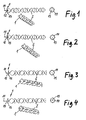
- FIG. 1 to 8 each in side view, perspective view and bottom view of some embodiments of static mixers according to the invention.
- a baffle plate 1 with upstream facing centric pin 11, a divergent transition into the actual plate, and star-like configuration provided in the embodiments of the Fig. 6 till 8 Several such baffles 1 are provided, namely in each case on the input side and in each case according to a group of mixing elements. 2
- the input-side plate is denoted by 1, and the mixing elements are denoted by 2.
- the further plates between successive groups of mixing elements 2 are in the Fig. 6 to 8 labeled 1a and 1b.
- the mixing elements 2 are formed in all the illustrated embodiments in a conventional manner, namely as arranged at 90 ° angularly offset mixing elements, each having the shape of a two-start coil section which undergoes a 180 ° rotation.
- the input-side baffle plate 1 (and also the optionally subsequent baffle plates 1a, 1b) each have an upstream facing central pin 11, an arcuate diverging transition region 12 which may be conical or pyramid-like, and the actual plate 13, respectively in the illustrated examples has four star arms, which protrude radially outward and depending on the embodiment form more or less wide passage openings 14 between them, which are more or less far in the radially outer region.
- the size of the passage openings 14 and their configuration, and accordingly the area size and configuration of the star arms of the plate 13, each depend significantly on the consistency of the materials to be mixed. It is understood that the smaller the passage openings, the greater the pressure loss and thus the necessary extrusion pressure. The tougher the material components to be mixed, the larger the passage openings accordingly.
- the mixing elements 2 are each offset by 90 ° from each other, and each mixing element undergoes a 180 ° rotation.
- this is only an example, it can also find other designs of mixing elements and other rotational offset angle application.
- the plates 1 each have a four-arm star configuration. But there may also be fewer or more star arms.
- each baffle plate 1 is oriented so that two of the four star arms lie in front of the entry edge of the subsequent mixing element.
Landscapes
- Chemical & Material Sciences (AREA)
- Dispersion Chemistry (AREA)
- Chemical Kinetics & Catalysis (AREA)
Abstract
Description
- Die Erfindung betrifft einen statischen Mischer zum Mischen von zwei Materialkomponenten beim Austritt aus zwei in ein gemeinsames Mischrohr führenden Austrittskanälen einer Zweikomponentenkartusche.
- Statische Mischer sind bekannt und bestehen aus einer Reihe von meist gleichen, axial aneinander gereihten und jeweils üblicherweise um 90°winkelversetzten Mischflügelelementen, die starr miteinander verbunden sind und in einem Mischrohr sitzen, das einlassseitig eine mit den Auslässen der Zweikomponentenkartusche verbindbare Hülse aufweist.
- Das Ziel bei der Konstruktion solcher statischer Mischer besteht darin, ein möglichst gutes Mischergebnis bei möglichst geringem Strömungswiderstand zu erzeugen. Es ist also wünschenswert, zur Widerstandsreduzierung mit möglichst wenigen Mischelementen auszukommen, andererseits aber am Ende des statischen Mischers einen homogen vermischten Materialstrom zu haben.
- Die Mischwirkung solcher statischer Mischer besteht darin, dass der aus den beiden Auslässen der Kammern der Zweikomponentenkartusche austretende Gesamtmaterialstrom möglichst effizient wiederholten Strangteilungen, richtungswechselnden Strangbewegungen und Strangzusammenführungen zu unterziehen, um dadurch die innige und homogene Vermischung der beiden Komponenten zu erzielen.
- Bei Zweikomponentenkartuschen, bei denen die Materialstränge der beiden Komponenten im wesentlichen koaxial in den Mischer eintreten, besteht zu dem das Problem, dass oft noch nach einer Reihe durchlaufener Mischelemente die innere Materialkomponente sich immer noch im wesentlichen innen und die äußere Materialkomponente sich immer noch im wesentlichen außen befindet und dadurch das Erreichen einer homogenen Durchmischung langwierig ist.
- Aufgabe der Erfindung ist es, einen solchen statischen Mischer zu schaffen, der zum Vermischen von koaxial aus einer Zweikomponentenkartusche austretenden Materialsträngen die oben genannten Ziele bei einer sehr einfachen Konstruktion möglichst gut erreicht.
- Diese Aufgabe wird gemäß der Erfindung durch den im Anspruch 1 angegebenen Aufbau eines statischen Mischers gelöst. Vorteilhafte Ausgestaltungen der Erfindung sind Gegenstand der Unteransprüche.
- Der erfindungsgemäße statische Mischer besteht also zunächst in bekannter Weise aus einer Anzahl axial aneinandergereihter und fest miteinander verbundener, jeweils zueinander winkelversetzter Mischelemente, die jeweils die Gestalt von Doppelwendelabschnitten haben können.
- Erfindungsgemäß ist eingangsseitig eine der Mischelementenreihe vorgeschaltete Prallplatte vorgesehen, die einen zentrischen, sich stromauf in den Materialstrom erstreckenden Zapfen oder Dorn aufweist, der in Strömungsrichtung divergierend in eine achssenkrechte Platte übergeht. Dabei hat die Platte eine etwa sternartige Konfiguration, deren Sternarme in Abhängigkeit von der Konsistenz der zu mischenden Materialien unterschiedlich flächig und groß gestaltet sein können, und zwischen ihren Sternarmen ebenfalls der Konsistenz in Form und Größe angepasste Durchtrittsöffnungen bilden, durch das das Material in einer entsprechenden Anzahl von Materialsträngen hindurchtritt und so in den Bereich des ersten Mischelements gelangt.
- Die Größe der Durchtrittsöffnungen zwischen den Sternarmen hängt also auch wieder von der Konsistenz der zu mischenden Materialien ab. Der Zapfen erstreckt sich in den Materialstrom der inneren Materialkomponente der koaxial aus der Zweikomponentenkartusche austretenden Materialkomponenten, und die vorzugsweise bogenförmig divergierende Gestaltung des Übergangs von dem Zapfen in die sternartige Platte dient dazu, den inneren Materialstrom effektiv und gleichmäßig über dem Querschnitt verteilt radial nach außen umzulenken, um ihn über den ganzen Mischerquerschnitt mit der radial außen eintretenden äußeren Materialkomponente zusammenzubringen, so dass die beiden koaxial aus der Zweikomponentenkartusche austretenden Materialstränge bereits in zusammengeführter Form schon in das erste Mischelement der Mischelementenreihe eintritt.
- Die sternartigen Arme der Platte, die zwischen sich Durchtrittsöffnungen bilden, bewirken, dass die zusammengeführten Materialien bereits in Gestalt einzelner Stränge in den Mischer eintreten, wo dann durch die aufeinanderfolgenden, drehversetzten und jeweils wendelförmigen Mischelemente fortgesetzte Strangaufteilungen, richtungswechselnde Strangumlenkungen, und Strangzusammenführungen erfolgen, wodurch das Mischen bewirkt wird.
- In weiterer Ausbildung der Erfindung können auch jeweils nach einzelnen Gruppen von aufeinanderfolgenden Mischelementen solche sternförmigen Platten gleicher oder ähnlicher Konfiguration zwischen mehreren aufeinanderfolgenden Gruppen von aneinandergereihten Mischelementen vorgesehen sein.
- Einige Ausführungsbeispiele der Erfindung sind in den anliegenden Zeichnungen dargestellt, und die Erfindung wird anhand dieser Ausführungsbeispiele nachstehend mehr im einzelnen kurz beschrieben.
- In den Zeichnungen zeigen die
Fig. 1 bis 8 jeweils in Seitenansicht, perspektivischer Ansicht und Unteransicht einige Ausführungsbeispiele von statischen Mischern nach der Erfindung. - Bei den Ausführungsformen nach den
Fig. 1 bis 5 ist jeweils nur eingangsseitig an der Reihe von aufeinanderfolgenden Mischelementen 2 eine Prallplatte 1 mit stromaufwärts weisendem zentrischem Zapfen 11, einem divergierenden Übergang in die eigentliche Platte, und sternartiger Konfiguration vorgesehen. Bei den Ausführungsformen nach denFig. 6 bis 8 sind mehrere solcher Prallplatten 1 vorgesehen, nämlich jeweils eingangsseitig und jeweils nach einer Gruppe von Mischelementen 2. - In allen Zeichnungsfiguren ist die eingangsseitige Platte mit 1 bezeichnet, und die Mischelemente sind mit 2 bezeichnet. Die weiteren Platten zwischen aufeinanderfolgenden Gruppen von Mischelementen 2 sind in den
Fig. 6 bis 8 mit 1a und 1b bezeichnet. - Die Mischelemente 2 sind bei allen dargestellten Ausführungsformen in einer üblichen Weise ausgebildet, nämlich als um jeweils 90° winkelversetzt angeordnete Mischelemente, die jeweils die Gestalt eines zweigängigen Wendelabschnitts haben, der eine 180°-Drehung durchläuft.
- Die eingangsseitige Prallplatte 1 (und ebenso die gegebenenfalls nachfolgenden Prallplatten 1a, 1b) haben jeweils einen stromaufwärts weisenden zentrischen Zapfen 11, einen bogenförmig divergierenden Übergangsbereich 12, der kegelig oder pyramidenartig ausgebildet sein kann, und die eigentliche Platte 13, die bei den dargestellten Beispielen jeweils vier Sternarme hat, die radial nach außen ragen und je nach Ausführungsform mehr oder weniger breite Durchtrittsöffnungen 14 zwischen sich bilden, die mehr oder weniger weit im radial äußeren Bereich liegen. Die Größe der Durchtrittsöffnungen 14 sowie deren Konfiguration, und dementsprechend die Flächengröße und Konfiguration der Sternarme der Platte 13, hängen jeweils maßgeblich von den Konsistenzen der zu durchmischenden Materialien ab. Es versteht sich, dass, je kleiner die Durchtrittsöffnungen sind, desto größer der Druckverlust und damit der notwendige Auspressdruck ist. Je zäher die zu vermischenden Materialkomponenten sind, desto größer sind dementsprechend auch die Durchtrittsöffnungen.
- Bei den Ausführungsbeispielen sind die Mischelemente 2 jeweils um 90° gegeneinander versetzt, und jedes Mischelement durchläuft eine 180°-Drehung. Dies ist allerdings nur beispielhaft, es können auch andere Gestaltungen von Mischelementen und andere Drehversatzwinkel Anwendung finden.
- Entsprechend der Konfiguration und Anordnung der Mischelemente haben bei den dargestellten Ausführungsbeispielen die Platten 1 jeweils eine vierarmige Sternkonfiguration. Es können aber auch weniger oder mehr Sternarme sein.
- Bei den dargestellten Ausführungsbeispielen ist jede Prallplatte 1 so orientiert, dass zwei der vier Sternarme vor der Eintrittkante des darauf folgenden Mischelements liegen.
Claims (8)
- Statischer Mischer zur Anordnung in einem Mischrohr, dessen Einlaß zur Aufnahme zweier im wesentlichen koaxialer Materialkomponentenstränge aus dem Auslaß einer Zweikomponentenkartusche bestimmt ist, mit einer Mehrzahl von axial aneinander gereiht angeordneten feststehenden Mischelementen (2), die jeweils drehwinkelversetzt aufeinander folgend angeordnet sind, dadurch gekennzeichnet, dass am Eintrittsende des statischen Mischers mindestens vor dem ersten Mischelement (2) eine Prallplatte (1) angeordnet ist, die einen stromaufwärts vorspringenden zentrischen Dorn oder Zapfen (11) aufweist, der in die eigentliche achssenkrechte Prallplatte (13) übergeht, die sternartig mit einer Anzahl von Sternarmen ausgebildet ist, die zwischen sich Durchtrittsöffnungen (14) bilden.
- Statischer Mischer nach Anspruch 1, wobei der Dorn oder Zapfen (11) über einen divergierenden Übergangsbereich (12) in die eigentliche Prallplatte übergeht.
- Statischer Mischer nach Anspruch 2, wobei der Übergangsbereich (12) konkav bogenförmig gewölbt und im übrigen kegel- oder pyramidenartig ausgebildet ist.
- Statischer Mischer nach einem der Ansprüche 1 bis 3, wobei die Prallplatte (13) vier kreuzförmig angeordnete Sternarme hat und vier Durchtrittsöffnungen zwischen den Sternarmen bildet.
- Statischer Mischer nach einem der Ansprüche 1 bis 4, wobei die Sternarme von einem kreisförmigen Mittelbereich der Prallplatte (13) ausgehen.
- Statischer Mischer nach einem der Ansprüche 1 bis 5, wobei die Sternarme sich von radial innen nach radial außen stetig oder bogenförmig oder in abgestufter Weise in ihrer Breite verjüngen.
- Statischer Mischer nach einem der Ansprüche 1 bis 6, wobei mindestens eine weitere Prallplatte (1) mit den Merkmalen nach einem oder mehreren der Ansprüche 1 bis 6 zwischen Gruppen von jeweils mehreren aufeinander folgenden Mischelementen (2) angeordnet ist.
- Statischer Mischer nach einem der Ansprüche 1 bis 7, wobei die oder jede Prallplatte so orientiert ist, dass die Eintrittskante des auf die Prallplatte folgenden Mischelements jeweils axial hinter einem Sternarm der Prallplatte (1) liegt.
Applications Claiming Priority (1)
| Application Number | Priority Date | Filing Date | Title |
|---|---|---|---|
| DE202011101066U DE202011101066U1 (de) | 2011-05-25 | 2011-05-25 | Statischer Mischer |
Publications (3)
| Publication Number | Publication Date |
|---|---|
| EP2527029A2 true EP2527029A2 (de) | 2012-11-28 |
| EP2527029A3 EP2527029A3 (de) | 2014-03-26 |
| EP2527029B1 EP2527029B1 (de) | 2016-08-31 |
Family
ID=44803292
Family Applications (1)
| Application Number | Title | Priority Date | Filing Date |
|---|---|---|---|
| EP12004072.0A Active EP2527029B1 (de) | 2011-05-25 | 2012-05-25 | Statischer Mischer |
Country Status (2)
| Country | Link |
|---|---|
| EP (1) | EP2527029B1 (de) |
| DE (1) | DE202011101066U1 (de) |
Cited By (7)
| Publication number | Priority date | Publication date | Assignee | Title |
|---|---|---|---|---|
| EP2764909A2 (de) | 2013-02-08 | 2014-08-13 | CHEMOFAST Anchoring GmbH | Mischvorrichtung für Zweikomponentenkartuschen |
| WO2019020768A1 (de) | 2017-07-28 | 2019-01-31 | Kettenbach Gmbh & Co. Kg | Mischer mit kompensationskanal und/oder staukammer |
| DE102017117199A1 (de) | 2017-07-28 | 2019-01-31 | 3lmed GmbH | Mischer mit Kompensationskanal und/oder Staukammer |
| DE102017128116A1 (de) | 2017-11-28 | 2019-05-29 | Coexal Gmbh | Mischerkomponente, Statischer Mischer und Verfahren zu deren Herstellung |
| CN110396038A (zh) * | 2019-09-02 | 2019-11-01 | 中国天辰工程有限公司 | 一种用于非均相的反应系统及应用该系统的反应工艺 |
| US10786790B2 (en) | 2015-10-30 | 2020-09-29 | Sulzer Mixpac Ag | Multicomponent static mixer for mixing components |
| EP4309772A1 (de) | 2022-07-19 | 2024-01-24 | Glue Tec Industrieklebstoffe GmbH & Co. Kg | Statischer mischer |
Families Citing this family (1)
| Publication number | Priority date | Publication date | Assignee | Title |
|---|---|---|---|---|
| FR3059412B1 (fr) * | 2016-11-30 | 2019-05-17 | Valeo Systemes Thermiques | Organe de mixage constitutif d'un dispositif d'homogeneisation de la distribution d'un fluide refrigerant a l'interieur de tubes d'un echangeur de chaleur |
Family Cites Families (6)
| Publication number | Priority date | Publication date | Assignee | Title |
|---|---|---|---|---|
| US4370062A (en) * | 1980-02-19 | 1983-01-25 | Moody Warren E | Dispensing gun for two-part adhesives |
| US4878624A (en) * | 1985-09-19 | 1989-11-07 | Hydro Energy Systems, Ltd. | Process for conditioning liquid petroleum |
| DE3618062A1 (de) * | 1986-05-28 | 1987-12-03 | Kachel Charlotte | Vorrichtung zum vermischen von pastoesen oder gelartigen komponenten |
| DE9207048U1 (de) * | 1992-05-25 | 1992-07-30 | Chemofast Korte-Jungermann GmbH & Co KG, 4156 Willich | Statikmischer |
| DE102004008755A1 (de) * | 2004-02-23 | 2005-09-08 | Hilti Ag | Statischer Mischer und seine Verwendung |
| WO2009125451A1 (ja) * | 2008-04-07 | 2009-10-15 | Tamura Kikuo | 活水化モジュール、及びこれを用いた活水装置 |
-
2011
- 2011-05-25 DE DE202011101066U patent/DE202011101066U1/de not_active Expired - Lifetime
-
2012
- 2012-05-25 EP EP12004072.0A patent/EP2527029B1/de active Active
Non-Patent Citations (1)
| Title |
|---|
| None |
Cited By (12)
| Publication number | Priority date | Publication date | Assignee | Title |
|---|---|---|---|---|
| EP2764909A2 (de) | 2013-02-08 | 2014-08-13 | CHEMOFAST Anchoring GmbH | Mischvorrichtung für Zweikomponentenkartuschen |
| DE102013002290A1 (de) | 2013-02-08 | 2014-08-28 | Chemofast Anchoring Gmbh | Mischvorrichtung für Zweikomponentenkartuschen |
| US10786790B2 (en) | 2015-10-30 | 2020-09-29 | Sulzer Mixpac Ag | Multicomponent static mixer for mixing components |
| WO2019020768A1 (de) | 2017-07-28 | 2019-01-31 | Kettenbach Gmbh & Co. Kg | Mischer mit kompensationskanal und/oder staukammer |
| DE102017117199A1 (de) | 2017-07-28 | 2019-01-31 | 3lmed GmbH | Mischer mit Kompensationskanal und/oder Staukammer |
| US11717794B2 (en) | 2017-07-28 | 2023-08-08 | 3lmed GmbH | Mixer |
| US11986785B2 (en) | 2017-07-28 | 2024-05-21 | 3lmed GmbH | Mixer having compensation channel and/or reservoir chamber |
| DE102017128116A1 (de) | 2017-11-28 | 2019-05-29 | Coexal Gmbh | Mischerkomponente, Statischer Mischer und Verfahren zu deren Herstellung |
| DE102017128116B4 (de) | 2017-11-28 | 2019-06-13 | Coexal Gmbh | Mischerkomponente, Statischer Mischer und Verfahren zu deren Herstellung |
| CN110396038A (zh) * | 2019-09-02 | 2019-11-01 | 中国天辰工程有限公司 | 一种用于非均相的反应系统及应用该系统的反应工艺 |
| EP4309772A1 (de) | 2022-07-19 | 2024-01-24 | Glue Tec Industrieklebstoffe GmbH & Co. Kg | Statischer mischer |
| WO2024017933A1 (de) | 2022-07-19 | 2024-01-25 | GlueTec Industrieklebstoffe GmbH & Co. KG | Statischer mischer |
Also Published As
| Publication number | Publication date |
|---|---|
| DE202011101066U1 (de) | 2011-09-15 |
| EP2527029A3 (de) | 2014-03-26 |
| EP2527029B1 (de) | 2016-08-31 |
Similar Documents
| Publication | Publication Date | Title |
|---|---|---|
| EP2527029B1 (de) | Statischer Mischer | |
| EP1924346B1 (de) | Mischelement zum invertieren und mischen von strömenden stoffen in einem strömungskanal, sowie bausatz und mischer enthaltend dergestalte mischelemente | |
| EP1110599B1 (de) | Dynamischer Mischer für zahnärztliche Abdruckmassen | |
| EP1216747B1 (de) | Statischer Mischer | |
| EP1967806B1 (de) | Vorrichtung zur wärmetauschenden und mischenden Behandlung von fluiden Medien | |
| EP2755769B1 (de) | Vorrichtung zum mischen | |
| EP2680959B1 (de) | Dynamischer mischer und dessen verwendung | |
| EP2848320A1 (de) | Zwischenstück zur Verbindung eines Vorratsbehälters mit einem statischen Mischer | |
| DE102011078508A1 (de) | Vollkegeldüse | |
| WO2006111273A1 (de) | Applikator für zwei oder mehr komponenten | |
| EP3408014A1 (de) | Hohlraum-x-mischer-wärmetauscher | |
| EP2548635B1 (de) | Dynamischer Mischer mit einer Dichtung | |
| DE2844753A1 (de) | Verfahren und vorrichtung zum strangpressen | |
| DE10152186C1 (de) | Brennstoffzellanlage mit einer Vorrichtung zur dosierten Zufuhr von sauerstoffhaltigem Medium an Dosierstellen eines Gaserzeugungssystems | |
| DE2262016A1 (de) | Mischeinrichtung | |
| EP2335817A2 (de) | Statischer Mischer | |
| EP2258468B1 (de) | Mischsystem für Zweikomponentenkartusche | |
| DE4202591C2 (de) | Vorrichtung zum Vormischen von wenigstens zwei pastösen Massen | |
| EP2258466A1 (de) | Mischsystem für Zweikomponentenkartusche | |
| DE3618062A1 (de) | Vorrichtung zum vermischen von pastoesen oder gelartigen komponenten | |
| EP3645149B1 (de) | Verteiler für ein fluid | |
| DE3539426A1 (de) | Statische mischvorrichtung fuer nieder- und hochviskose stoffe | |
| DE202006012130U1 (de) | Statischer Vierkant-Wendelmischer | |
| WO2019020764A1 (de) | Mischer | |
| DE202008004552U1 (de) | Vorrichtung zum Mischen und zur Abgabe von Kunststoffmassen |
Legal Events
| Date | Code | Title | Description |
|---|---|---|---|
| PUAI | Public reference made under article 153(3) epc to a published international application that has entered the european phase |
Free format text: ORIGINAL CODE: 0009012 |
|
| AK | Designated contracting states |
Kind code of ref document: A2 Designated state(s): AL AT BE BG CH CY CZ DE DK EE ES FI FR GB GR HR HU IE IS IT LI LT LU LV MC MK MT NL NO PL PT RO RS SE SI SK SM TR |
|
| AX | Request for extension of the european patent |
Extension state: BA ME |
|
| PUAL | Search report despatched |
Free format text: ORIGINAL CODE: 0009013 |
|
| AK | Designated contracting states |
Kind code of ref document: A3 Designated state(s): AL AT BE BG CH CY CZ DE DK EE ES FI FR GB GR HR HU IE IS IT LI LT LU LV MC MK MT NL NO PL PT RO RS SE SI SK SM TR |
|
| AX | Request for extension of the european patent |
Extension state: BA ME |
|
| RIC1 | Information provided on ipc code assigned before grant |
Ipc: B01F 5/06 20060101AFI20140219BHEP |
|
| 17P | Request for examination filed |
Effective date: 20140925 |
|
| RBV | Designated contracting states (corrected) |
Designated state(s): AL AT BE BG CH CY CZ DE DK EE ES FI FR GB GR HR HU IE IS IT LI LT LU LV MC MK MT NL NO PL PT RO RS SE SI SK SM TR |
|
| 17Q | First examination report despatched |
Effective date: 20150401 |
|
| GRAP | Despatch of communication of intention to grant a patent |
Free format text: ORIGINAL CODE: EPIDOSNIGR1 |
|
| INTG | Intention to grant announced |
Effective date: 20160607 |
|
| GRAS | Grant fee paid |
Free format text: ORIGINAL CODE: EPIDOSNIGR3 |
|
| GRAA | (expected) grant |
Free format text: ORIGINAL CODE: 0009210 |
|
| AK | Designated contracting states |
Kind code of ref document: B1 Designated state(s): AL AT BE BG CH CY CZ DE DK EE ES FI FR GB GR HR HU IE IS IT LI LT LU LV MC MK MT NL NO PL PT RO RS SE SI SK SM TR |
|
| REG | Reference to a national code |
Ref country code: CH Ref legal event code: EP Ref country code: GB Ref legal event code: FG4D Free format text: NOT ENGLISH |
|
| REG | Reference to a national code |
Ref country code: IE Ref legal event code: FG4D Free format text: LANGUAGE OF EP DOCUMENT: GERMAN |
|
| REG | Reference to a national code |
Ref country code: AT Ref legal event code: REF Ref document number: 824515 Country of ref document: AT Kind code of ref document: T Effective date: 20161015 |
|
| REG | Reference to a national code |
Ref country code: DE Ref legal event code: R096 Ref document number: 502012008089 Country of ref document: DE |
|
| REG | Reference to a national code |
Ref country code: LT Ref legal event code: MG4D |
|
| REG | Reference to a national code |
Ref country code: NL Ref legal event code: MP Effective date: 20160831 |
|
| PG25 | Lapsed in a contracting state [announced via postgrant information from national office to epo] |
Ref country code: NO Free format text: LAPSE BECAUSE OF FAILURE TO SUBMIT A TRANSLATION OF THE DESCRIPTION OR TO PAY THE FEE WITHIN THE PRESCRIBED TIME-LIMIT Effective date: 20161130 Ref country code: LT Free format text: LAPSE BECAUSE OF FAILURE TO SUBMIT A TRANSLATION OF THE DESCRIPTION OR TO PAY THE FEE WITHIN THE PRESCRIBED TIME-LIMIT Effective date: 20160831 Ref country code: RS Free format text: LAPSE BECAUSE OF FAILURE TO SUBMIT A TRANSLATION OF THE DESCRIPTION OR TO PAY THE FEE WITHIN THE PRESCRIBED TIME-LIMIT Effective date: 20160831 Ref country code: FI Free format text: LAPSE BECAUSE OF FAILURE TO SUBMIT A TRANSLATION OF THE DESCRIPTION OR TO PAY THE FEE WITHIN THE PRESCRIBED TIME-LIMIT Effective date: 20160831 Ref country code: HR Free format text: LAPSE BECAUSE OF FAILURE TO SUBMIT A TRANSLATION OF THE DESCRIPTION OR TO PAY THE FEE WITHIN THE PRESCRIBED TIME-LIMIT Effective date: 20160831 |
|
| PG25 | Lapsed in a contracting state [announced via postgrant information from national office to epo] |
Ref country code: LV Free format text: LAPSE BECAUSE OF FAILURE TO SUBMIT A TRANSLATION OF THE DESCRIPTION OR TO PAY THE FEE WITHIN THE PRESCRIBED TIME-LIMIT Effective date: 20160831 Ref country code: GR Free format text: LAPSE BECAUSE OF FAILURE TO SUBMIT A TRANSLATION OF THE DESCRIPTION OR TO PAY THE FEE WITHIN THE PRESCRIBED TIME-LIMIT Effective date: 20161201 Ref country code: NL Free format text: LAPSE BECAUSE OF FAILURE TO SUBMIT A TRANSLATION OF THE DESCRIPTION OR TO PAY THE FEE WITHIN THE PRESCRIBED TIME-LIMIT Effective date: 20160831 Ref country code: SE Free format text: LAPSE BECAUSE OF FAILURE TO SUBMIT A TRANSLATION OF THE DESCRIPTION OR TO PAY THE FEE WITHIN THE PRESCRIBED TIME-LIMIT Effective date: 20160831 Ref country code: ES Free format text: LAPSE BECAUSE OF FAILURE TO SUBMIT A TRANSLATION OF THE DESCRIPTION OR TO PAY THE FEE WITHIN THE PRESCRIBED TIME-LIMIT Effective date: 20160831 |
|
| PG25 | Lapsed in a contracting state [announced via postgrant information from national office to epo] |
Ref country code: RO Free format text: LAPSE BECAUSE OF FAILURE TO SUBMIT A TRANSLATION OF THE DESCRIPTION OR TO PAY THE FEE WITHIN THE PRESCRIBED TIME-LIMIT Effective date: 20160831 Ref country code: EE Free format text: LAPSE BECAUSE OF FAILURE TO SUBMIT A TRANSLATION OF THE DESCRIPTION OR TO PAY THE FEE WITHIN THE PRESCRIBED TIME-LIMIT Effective date: 20160831 |
|
| REG | Reference to a national code |
Ref country code: FR Ref legal event code: PLFP Year of fee payment: 6 |
|
| PG25 | Lapsed in a contracting state [announced via postgrant information from national office to epo] |
Ref country code: BG Free format text: LAPSE BECAUSE OF FAILURE TO SUBMIT A TRANSLATION OF THE DESCRIPTION OR TO PAY THE FEE WITHIN THE PRESCRIBED TIME-LIMIT Effective date: 20161130 Ref country code: SK Free format text: LAPSE BECAUSE OF FAILURE TO SUBMIT A TRANSLATION OF THE DESCRIPTION OR TO PAY THE FEE WITHIN THE PRESCRIBED TIME-LIMIT Effective date: 20160831 Ref country code: PT Free format text: LAPSE BECAUSE OF FAILURE TO SUBMIT A TRANSLATION OF THE DESCRIPTION OR TO PAY THE FEE WITHIN THE PRESCRIBED TIME-LIMIT Effective date: 20170102 Ref country code: DK Free format text: LAPSE BECAUSE OF FAILURE TO SUBMIT A TRANSLATION OF THE DESCRIPTION OR TO PAY THE FEE WITHIN THE PRESCRIBED TIME-LIMIT Effective date: 20160831 Ref country code: SM Free format text: LAPSE BECAUSE OF FAILURE TO SUBMIT A TRANSLATION OF THE DESCRIPTION OR TO PAY THE FEE WITHIN THE PRESCRIBED TIME-LIMIT Effective date: 20160831 Ref country code: PL Free format text: LAPSE BECAUSE OF FAILURE TO SUBMIT A TRANSLATION OF THE DESCRIPTION OR TO PAY THE FEE WITHIN THE PRESCRIBED TIME-LIMIT Effective date: 20160831 Ref country code: CZ Free format text: LAPSE BECAUSE OF FAILURE TO SUBMIT A TRANSLATION OF THE DESCRIPTION OR TO PAY THE FEE WITHIN THE PRESCRIBED TIME-LIMIT Effective date: 20160831 |
|
| REG | Reference to a national code |
Ref country code: DE Ref legal event code: R097 Ref document number: 502012008089 Country of ref document: DE |
|
| PG25 | Lapsed in a contracting state [announced via postgrant information from national office to epo] |
Ref country code: IT Free format text: LAPSE BECAUSE OF FAILURE TO SUBMIT A TRANSLATION OF THE DESCRIPTION OR TO PAY THE FEE WITHIN THE PRESCRIBED TIME-LIMIT Effective date: 20160831 |
|
| PLBE | No opposition filed within time limit |
Free format text: ORIGINAL CODE: 0009261 |
|
| STAA | Information on the status of an ep patent application or granted ep patent |
Free format text: STATUS: NO OPPOSITION FILED WITHIN TIME LIMIT |
|
| 26N | No opposition filed |
Effective date: 20170601 |
|
| PG25 | Lapsed in a contracting state [announced via postgrant information from national office to epo] |
Ref country code: LU Free format text: LAPSE BECAUSE OF NON-PAYMENT OF DUE FEES Effective date: 20170531 Ref country code: SI Free format text: LAPSE BECAUSE OF FAILURE TO SUBMIT A TRANSLATION OF THE DESCRIPTION OR TO PAY THE FEE WITHIN THE PRESCRIBED TIME-LIMIT Effective date: 20160831 |
|
| REG | Reference to a national code |
Ref country code: CH Ref legal event code: PL |
|
| PG25 | Lapsed in a contracting state [announced via postgrant information from national office to epo] |
Ref country code: MC Free format text: LAPSE BECAUSE OF FAILURE TO SUBMIT A TRANSLATION OF THE DESCRIPTION OR TO PAY THE FEE WITHIN THE PRESCRIBED TIME-LIMIT Effective date: 20160831 |
|
| REG | Reference to a national code |
Ref country code: IE Ref legal event code: MM4A |
|
| PG25 | Lapsed in a contracting state [announced via postgrant information from national office to epo] |
Ref country code: CH Free format text: LAPSE BECAUSE OF NON-PAYMENT OF DUE FEES Effective date: 20170531 Ref country code: LI Free format text: LAPSE BECAUSE OF NON-PAYMENT OF DUE FEES Effective date: 20170531 |
|
| PG25 | Lapsed in a contracting state [announced via postgrant information from national office to epo] |
Ref country code: LU Free format text: LAPSE BECAUSE OF NON-PAYMENT OF DUE FEES Effective date: 20170525 |
|
| REG | Reference to a national code |
Ref country code: BE Ref legal event code: MM Effective date: 20170531 |
|
| PG25 | Lapsed in a contracting state [announced via postgrant information from national office to epo] |
Ref country code: IE Free format text: LAPSE BECAUSE OF NON-PAYMENT OF DUE FEES Effective date: 20170525 |
|
| REG | Reference to a national code |
Ref country code: FR Ref legal event code: PLFP Year of fee payment: 7 |
|
| REG | Reference to a national code |
Ref country code: AT Ref legal event code: MM01 Ref document number: 824515 Country of ref document: AT Kind code of ref document: T Effective date: 20170525 |
|
| PG25 | Lapsed in a contracting state [announced via postgrant information from national office to epo] |
Ref country code: BE Free format text: LAPSE BECAUSE OF NON-PAYMENT OF DUE FEES Effective date: 20170531 Ref country code: AT Free format text: LAPSE BECAUSE OF NON-PAYMENT OF DUE FEES Effective date: 20170525 |
|
| PG25 | Lapsed in a contracting state [announced via postgrant information from national office to epo] |
Ref country code: MT Free format text: LAPSE BECAUSE OF FAILURE TO SUBMIT A TRANSLATION OF THE DESCRIPTION OR TO PAY THE FEE WITHIN THE PRESCRIBED TIME-LIMIT Effective date: 20160831 |
|
| PG25 | Lapsed in a contracting state [announced via postgrant information from national office to epo] |
Ref country code: AL Free format text: LAPSE BECAUSE OF FAILURE TO SUBMIT A TRANSLATION OF THE DESCRIPTION OR TO PAY THE FEE WITHIN THE PRESCRIBED TIME-LIMIT Effective date: 20160831 |
|
| PG25 | Lapsed in a contracting state [announced via postgrant information from national office to epo] |
Ref country code: HU Free format text: LAPSE BECAUSE OF FAILURE TO SUBMIT A TRANSLATION OF THE DESCRIPTION OR TO PAY THE FEE WITHIN THE PRESCRIBED TIME-LIMIT; INVALID AB INITIO Effective date: 20120525 |
|
| PG25 | Lapsed in a contracting state [announced via postgrant information from national office to epo] |
Ref country code: CY Free format text: LAPSE BECAUSE OF NON-PAYMENT OF DUE FEES Effective date: 20160831 |
|
| PG25 | Lapsed in a contracting state [announced via postgrant information from national office to epo] |
Ref country code: MK Free format text: LAPSE BECAUSE OF FAILURE TO SUBMIT A TRANSLATION OF THE DESCRIPTION OR TO PAY THE FEE WITHIN THE PRESCRIBED TIME-LIMIT Effective date: 20160831 |
|
| PG25 | Lapsed in a contracting state [announced via postgrant information from national office to epo] |
Ref country code: TR Free format text: LAPSE BECAUSE OF FAILURE TO SUBMIT A TRANSLATION OF THE DESCRIPTION OR TO PAY THE FEE WITHIN THE PRESCRIBED TIME-LIMIT Effective date: 20160831 |
|
| PG25 | Lapsed in a contracting state [announced via postgrant information from national office to epo] |
Ref country code: IS Free format text: LAPSE BECAUSE OF FAILURE TO SUBMIT A TRANSLATION OF THE DESCRIPTION OR TO PAY THE FEE WITHIN THE PRESCRIBED TIME-LIMIT Effective date: 20161231 |
|
| REG | Reference to a national code |
Ref country code: DE Ref legal event code: R079 Ref document number: 502012008089 Country of ref document: DE Free format text: PREVIOUS MAIN CLASS: B01F0005060000 Ipc: B01F0025400000 |
|
| REG | Reference to a national code |
Ref country code: DE Ref legal event code: R082 Ref document number: 502012008089 Country of ref document: DE Representative=s name: FLEUCHAUS & GALLO PARTNERSCHAFT MBB - PATENT- , DE Ref country code: DE Ref legal event code: R082 Ref document number: 502012008089 Country of ref document: DE Representative=s name: FLEUCHAUS & GALLO PARTNERSCHAFT MBB PATENTANWA, DE |
|
| PGFP | Annual fee paid to national office [announced via postgrant information from national office to epo] |
Ref country code: DE Payment date: 20230509 Year of fee payment: 12 |
|
| PGFP | Annual fee paid to national office [announced via postgrant information from national office to epo] |
Ref country code: GB Payment date: 20240521 Year of fee payment: 13 |
|
| PGFP | Annual fee paid to national office [announced via postgrant information from national office to epo] |
Ref country code: FR Payment date: 20240522 Year of fee payment: 13 |