EP2526407B1 - Méthode pour la détection d'un signal optique non linéaire résonant et dispositif pour la mise en oeuvre de ladite méthode - Google Patents
Méthode pour la détection d'un signal optique non linéaire résonant et dispositif pour la mise en oeuvre de ladite méthode Download PDFInfo
- Publication number
- EP2526407B1 EP2526407B1 EP11703160.9A EP11703160A EP2526407B1 EP 2526407 B1 EP2526407 B1 EP 2526407B1 EP 11703160 A EP11703160 A EP 11703160A EP 2526407 B1 EP2526407 B1 EP 2526407B1
- Authority
- EP
- European Patent Office
- Prior art keywords
- beams
- sample
- resonant
- excitation
- resonant medium
- Prior art date
- Legal status (The legal status is an assumption and is not a legal conclusion. Google has not performed a legal analysis and makes no representation as to the accuracy of the status listed.)
- Not-in-force
Links
- 230000003287 optical effect Effects 0.000 title claims description 64
- 238000000034 method Methods 0.000 title claims description 59
- 230000005284 excitation Effects 0.000 claims description 91
- 238000001514 detection method Methods 0.000 claims description 45
- 230000003993 interaction Effects 0.000 claims description 23
- 238000001069 Raman spectroscopy Methods 0.000 claims description 20
- 230000009021 linear effect Effects 0.000 claims description 12
- 238000001228 spectrum Methods 0.000 claims description 9
- 238000012545 processing Methods 0.000 claims description 6
- 238000004364 calculation method Methods 0.000 claims description 3
- 239000000523 sample Substances 0.000 description 66
- ZMXDDKWLCZADIW-UHFFFAOYSA-N N,N-Dimethylformamide Chemical compound CN(C)C=O ZMXDDKWLCZADIW-UHFFFAOYSA-N 0.000 description 22
- 230000010349 pulsation Effects 0.000 description 22
- 230000008569 process Effects 0.000 description 15
- 238000001237 Raman spectrum Methods 0.000 description 11
- 238000000386 microscopy Methods 0.000 description 9
- 238000004088 simulation Methods 0.000 description 9
- 239000002904 solvent Substances 0.000 description 9
- 239000011521 glass Substances 0.000 description 8
- 238000004611 spectroscopical analysis Methods 0.000 description 8
- 238000009792 diffusion process Methods 0.000 description 7
- 239000013598 vector Substances 0.000 description 7
- 238000013459 approach Methods 0.000 description 5
- 238000003384 imaging method Methods 0.000 description 5
- 230000003595 spectral effect Effects 0.000 description 5
- XLYOFNOQVPJJNP-UHFFFAOYSA-N water Substances O XLYOFNOQVPJJNP-UHFFFAOYSA-N 0.000 description 5
- 238000004458 analytical method Methods 0.000 description 4
- 230000000694 effects Effects 0.000 description 4
- 239000000835 fiber Substances 0.000 description 4
- 239000000126 substance Substances 0.000 description 4
- 229910052691 Erbium Inorganic materials 0.000 description 3
- 229910052769 Ytterbium Inorganic materials 0.000 description 3
- 238000010521 absorption reaction Methods 0.000 description 3
- 238000010586 diagram Methods 0.000 description 3
- UYAHIZSMUZPPFV-UHFFFAOYSA-N erbium Chemical compound [Er] UYAHIZSMUZPPFV-UHFFFAOYSA-N 0.000 description 3
- NAWDYIZEMPQZHO-UHFFFAOYSA-N ytterbium Chemical compound [Yb] NAWDYIZEMPQZHO-UHFFFAOYSA-N 0.000 description 3
- 238000004566 IR spectroscopy Methods 0.000 description 2
- 241000135309 Processus Species 0.000 description 2
- 239000012472 biological sample Substances 0.000 description 2
- 239000007788 liquid Substances 0.000 description 2
- 238000012986 modification Methods 0.000 description 2
- 230000004048 modification Effects 0.000 description 2
- 230000002441 reversible effect Effects 0.000 description 2
- 230000002269 spontaneous effect Effects 0.000 description 2
- 230000007704 transition Effects 0.000 description 2
- 239000004793 Polystyrene Substances 0.000 description 1
- 229910009372 YVO4 Inorganic materials 0.000 description 1
- 230000005540 biological transmission Effects 0.000 description 1
- 238000002082 coherent anti-Stokes Raman spectroscopy Methods 0.000 description 1
- 230000001427 coherent effect Effects 0.000 description 1
- 239000013078 crystal Substances 0.000 description 1
- 238000000295 emission spectrum Methods 0.000 description 1
- 239000011159 matrix material Substances 0.000 description 1
- 238000005259 measurement Methods 0.000 description 1
- 239000012528 membrane Substances 0.000 description 1
- 230000009022 nonlinear effect Effects 0.000 description 1
- 239000013307 optical fiber Substances 0.000 description 1
- 239000004038 photonic crystal Substances 0.000 description 1
- 229920002223 polystyrene Polymers 0.000 description 1
- 210000001747 pupil Anatomy 0.000 description 1
- 230000005855 radiation Effects 0.000 description 1
- 238000012552 review Methods 0.000 description 1
- 229910052594 sapphire Inorganic materials 0.000 description 1
- 239000010980 sapphire Substances 0.000 description 1
- 239000007787 solid Substances 0.000 description 1
- 238000012732 spatial analysis Methods 0.000 description 1
- 241000894007 species Species 0.000 description 1
- 238000001845 vibrational spectrum Methods 0.000 description 1
Images


Classifications
-
- G—PHYSICS
- G01—MEASURING; TESTING
- G01N—INVESTIGATING OR ANALYSING MATERIALS BY DETERMINING THEIR CHEMICAL OR PHYSICAL PROPERTIES
- G01N21/00—Investigating or analysing materials by the use of optical means, i.e. using sub-millimetre waves, infrared, visible or ultraviolet light
- G01N21/62—Systems in which the material investigated is excited whereby it emits light or causes a change in wavelength of the incident light
- G01N21/63—Systems in which the material investigated is excited whereby it emits light or causes a change in wavelength of the incident light optically excited
- G01N21/65—Raman scattering
-
- G—PHYSICS
- G01—MEASURING; TESTING
- G01J—MEASUREMENT OF INTENSITY, VELOCITY, SPECTRAL CONTENT, POLARISATION, PHASE OR PULSE CHARACTERISTICS OF INFRARED, VISIBLE OR ULTRAVIOLET LIGHT; COLORIMETRY; RADIATION PYROMETRY
- G01J3/00—Spectrometry; Spectrophotometry; Monochromators; Measuring colours
- G01J3/28—Investigating the spectrum
- G01J3/44—Raman spectrometry; Scattering spectrometry ; Fluorescence spectrometry
- G01J3/4412—Scattering spectrometry
-
- G—PHYSICS
- G01—MEASURING; TESTING
- G01N—INVESTIGATING OR ANALYSING MATERIALS BY DETERMINING THEIR CHEMICAL OR PHYSICAL PROPERTIES
- G01N21/00—Investigating or analysing materials by the use of optical means, i.e. using sub-millimetre waves, infrared, visible or ultraviolet light
- G01N21/62—Systems in which the material investigated is excited whereby it emits light or causes a change in wavelength of the incident light
- G01N21/63—Systems in which the material investigated is excited whereby it emits light or causes a change in wavelength of the incident light optically excited
- G01N21/65—Raman scattering
- G01N21/658—Raman scattering enhancement Raman, e.g. surface plasmons
-
- G—PHYSICS
- G01—MEASURING; TESTING
- G01N—INVESTIGATING OR ANALYSING MATERIALS BY DETERMINING THEIR CHEMICAL OR PHYSICAL PROPERTIES
- G01N21/00—Investigating or analysing materials by the use of optical means, i.e. using sub-millimetre waves, infrared, visible or ultraviolet light
- G01N21/62—Systems in which the material investigated is excited whereby it emits light or causes a change in wavelength of the incident light
- G01N21/63—Systems in which the material investigated is excited whereby it emits light or causes a change in wavelength of the incident light optically excited
- G01N21/65—Raman scattering
- G01N2021/653—Coherent methods [CARS]
- G01N2021/655—Stimulated Raman
Definitions
- the present invention relates to a method for detecting a non-linear resonant optical signal and a device for implementing said method. It applies in particular to the detection of broadcast signals CARS.
- Vibrational optical techniques are methods that aim to use the light / matter interaction to obtain information about these molecular vibrations.
- the best known of these techniques is infrared spectroscopy (IR) which observes the specific absorption lines of the chemical bonds present in a sample.
- IR infrared spectroscopy
- the Raman scattering (named after physicist Chandrasekhara Venkata Raman who discovered the effect) makes it possible to use visible light to access the vibrational spectrum of molecules that interact with a light beam.
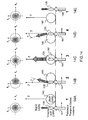
- a pulsating pump wave ⁇ P incident on a molecule is inelastically diffused into a so-called Stokes pulsation wave ⁇ S ( Figure 1A ) and a so-called anti-Stokes wave of pulsation ⁇ AS ( Figure 1B ).
- the Stokes and anti-Stokes waves correspond to an absorption from respectively the fundamental or excited vibrational level.
- the process generating the anti-Stokes wave, starting from the excited vibrational level (B), is much less likely than the process creating the Stokes wave, which is the only one observed in practice in spontaneous Raman spectroscopy.
- a detailed study of the spectral distribution of Stokes waves provides information on the densities of chemical bonds present in the sample. This spontaneous inelastic scattering process is very inefficient compared to fluorescence (the Raman cross sections are of the order of 10 -30 cm 2 / molecule, compared with the 1-photon absorption cross section of a fluorophore which reaches 10 -16 cm 2 / molecule).
- CARS Coherent Anti-Stokes Raman Scattering
- Raman Spectroscopy is a four-wave mixing process that addresses vibrational bonds. present in a sample. This process is for example described in RW Boyd, Nonlinear Optics (Boston Academic Press, 1992) ). It is a question of sending two laser pulses of pulsations ⁇ p and ⁇ s (or frequencies v p and v s ) whose difference of pulsations is made equal to the pulsation ⁇ of the vibrational level which one wants to address.
- the presence of this new radiation ⁇ as is the signature of the presence of the vibrating link at the ⁇ pulse in the sample.
- a first implementation of CARS is to send on the sample two spectrally fine picosecond pulses whose pulse difference will only address a specific vibrational connection. For optimal identification, all the vibrational links present in the sample are searched for. For this, one operates in said mode "Multiplex CARS" (see for example M.
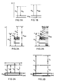
- the Figures 4 to 6 illustrate the method.
- the method consists in making a CARS differential image between an object and its symmetrical relative to a transverse interface 43 between a resonant medium (reference 41 on the Figures 4A and 4B ) and a non-resonant medium (referenced 42 on the Figures 4A, 4B ).
- the nonlinear susceptibility of the 3rd order is defined in the resonant medium 41 by a resonant term ⁇ (3) 1R and a non-resonant term ⁇ (3) 1NR .
- the non-resonant medium 42 it is defined by the non-resonant term ⁇ (3) 2NR .
- an active volume CARS 45 (instead of focusing the pump beam and Stokes pulses and ⁇ p ⁇ s respectively) located on the transverse interface 43 between the resonant medium and the medium non-resonant.
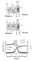
- An experimental implementation of the method is illustrated on the Figure 6B and experimental results are presented on the Figure 6A .
- the Figure 6B represents a sample consisting of a layer 61 of DMF (N, N-dimethylformamide) between two glass plates 62, 63.
- DMF N, N-dimethylformamide
- the situation ⁇ corresponds to the case where the pump and Stokes beams are focused on the glass-DMF interface (interface between 62 and 61), while situation ⁇ corresponds to the case where the excitation beams are focused on the DMF-glass interface (interface between 61 and 63).
- This method has a number of disadvantages. It is notably limited to symmetrical samples, such as the one represented on the Figure 6B , or reversible, in order to have access to the resonant / non-resonant interfaces on the one hand and non-resonant / resonant interfaces on the other hand. This presents a limitation in the case of biological samples that present rarely these properties. On the other hand, if it allows applications in spectroscopy, this method is limited for applications in microscopy.
- the document US2007 / 0121119 describes an example of CARS microscopy where, using a mirror system, the pump beam is incident on a sample by two opposite directions.
- the resulting interference of the CARS signals makes it possible to improve the spatial resolution.
- the present invention proposes an original device for detecting a non-linear resonant optical signal, based on the principle of detection at the transverse interfaces as described in the prior art, but which can be applied to any sample having an interface between a resonant medium and a non-resonant medium, both for spectroscopy and microscopy applications.
- the invention relates to a device for the detection of a non-linear resonant optical signal induced in a sample of a type comprising a resonant medium and a non-resonant medium forming an interface
- the device comprising: a source of emission at least a first excitation light beam, said pump beam, at a first given pulsation ⁇ p adapted to the excitation of the resonant medium of a sample of the given type, a first optical module adapted to the detection of the optical signal non-linear resulting from the interaction of said pump beam with the sample when said pump beam is incident on the sample along an optical axis and intercepts the sample at a given position of a transverse interface between the resonant medium and the medium resonant of the sample, reflection means of said pump beam, arranged so that said reflected pump beam intercepts the said transverse interface substantially at the same position as said incident pump beam, a second optical module adapted to the detection of the nonlinear optical signal resulting from
- the emission source makes it possible to transmit a pulsation pump beam ⁇ p and a pulsation Stokes beam ⁇ s
- the nonlinear optical signal resulting from the interaction of said pump and stokes beams is a so-called signal CARS distributed signal
- the difference of the signals detected by the first and the second detection module is characteristic of a Raman resonance of the resonant medium.
- the device according to the invention comprises a focus objective of the incident excitation beams in a common focusing volume, allowing said interface between the resonant medium and the non-resonant medium to be intercepted and a non-linear signal collection objective resulting from the interaction of the incident excitation beams with the sample, said collection objective being identical to the objective of focussing the incident beams and the collecting lens forming a focusing objective of the reflected excitation beams and focusing objective of the incident beams forming a nonlinear signal collection objective resulting from the interaction of the excitation beams reflect with the sample.
- each of the optical detection modules comprises an image recording device, the nonlinear optical signal being collected in each of the optical detection modules respectively in directions symmetrical with respect to the optical axis, the difference being performed for each pair of signals thus detected.
- an angular scanning device of the excitation beams allows the excitation beams to intercept the sample at different positions of the interface between the resonant and non-resonant medium.
- the emission source emits at least one variable wavelength excitation beam, making it possible to obtain a spectrum of the vibrational or electronic resonances of the resonant medium.
- the invention relates to a method for the detection of a non-linear resonant optical signal induced in a sample, the sample comprising a resonant medium and a non-resonant medium forming an interface, the method comprising: at least one first excitation light beam of the resonant medium, said pump beam, at a first given pulsation ⁇ p, said pump beam being incident on the sample along an optical axis, and intercepting the sample at a given position d a transverse interface between the resonant and non-resonant medium, the detection of a first nonlinear optical signal resulting from the interaction of said excitation beam or beams with the sample, the reflection of said excitation beam or beams, the or the beams of excitation thus reflected intercepting said transverse interface substantially at the same position as the incident excitation beam or beams, the delegate ction of a second nonlinear optical signal resulting from the interaction of said reflected excitation beam (s) with the sample, the processing of the
- the first and second nonlinear optical signals are respectively detected in directions symmetrical with respect to the optical axis of the incident excitation beams, the difference being made for each pair of signals thus detected.
- the excitation beams undergo an angular sweep to intercept the sample at different positions of the interface between the resonant and non-resonant medium.
- At least one of the excitation beams has a variable emission wavelength, making it possible to obtain a spectrum of the vibrational or electronic resonances of the resonant medium.
- FIGS. 7A and 7B illustrate by two schemes the principle of the detection method according to the invention in the case of the CARS diffusion.
- a pulsating pump beam ⁇ p and a colinear pulse stokes beam ⁇ s intercept a transverse interface 70, that is to say having a non-zero component in a plane perpendicular to the axis of the beams. incident (optical axis), between a non-resonant medium and a resonant medium.
- the two beams are focused and the common focusing volume of the beams that intercept the transverse interface 70 is noted.
- the excitation beams pass through the interface in a first direction, called the ⁇ -position.
- the intensities of the diffused CARS signals I ⁇ (Fwd) and I ⁇ (Fwd) are respectively measured in the two situations ⁇ and ⁇ , and their difference ⁇ I Fwd is calculated, after calibration, to give a signal which the applicant has shown that it is proportional to the imaginary part Im [ ⁇ (3) 1R ] of the non-linear susceptibility of order 3 of the resonant medium.
- a single pulse of the pump beam and the stokes beam is used to excite the sample in the situations a and ⁇ , making it possible to increase the signal-to-noise ratio compared with the method according to the prior art such that described in Figures 4 to 6 .
- Dz-CARS Making the difference of the CARS signals generated by an object and its symmetrical with respect to a plane perpendicular to the optical axis, the method according to the invention is named Dz-CARS in the following description (for Differential imaging in Z symmetry) .
- the figure 8A illustrates an exemplary device for implementing the detection method according to the invention.
- the detection device 800 generally comprises a laser system 801 enabling the emission of a first pulsation excitation beam ⁇ p (pump beam) and a second pulsation excitation beam ⁇ s (Stokes beam), collinear. , the two excitation beams being symbolized by the arrow 802.
- the device 800 further comprises an optical element, for example a reflecting plate 804, for sending the two excitation beams into a first optical detection module of the device generally referenced 803, in a main direction Z.
- the laser system 801 comprises, for example, in a so-called two-color application, two spectrally thin tunable laser sources 808, for example of the Titanium-Sapphire type, emitting between 690 and 1000 nm, pumped by a pump laser 809, Nd type: YVO4 emitting at 532 nm.
- the tunable lasers emit, for example, picosecond pulses, typically of the order of 3 ⁇ s, to form the pulsation pump excitation beams ⁇ p (of typical wavelength 730 nm) and pulsating Stokes ⁇ s .
- a pulse picker 810 (or “pulse picker") can be used to reduce the rate of pump and probe excitation lasers without reducing the peak power of the pulses.
- a Stokes beam or a tunable pump beam notably makes it possible to scan the anti-Stokes emission spectrum for spectroscopic applications intended to determine the Raman spectrum of the resonant medium.
- Other tunable laser sources may be used, for example of the optical parametric oscillator (OPO) type, optical parametric amplifier (OPA), Nd-type picosecond oscillators: glass, Ytterbium or Erbium doped fiber lasers, etc.
- the sources can also be nanosecond or femtosecond laser sources, depending on the spectral width of the Raman lines that one wants to observe. However, the nanosecond pulses, if very good from a spectral point of view, have a lower peak power than the ps pulses.
- the first optical detection module 803 comprises a focusing objective 807 for focusing the pump and Stokes beams into a common focusing volume for the analysis of the sample 805, shown in FIG. Figure 8B .
- the use of a focus lens is particularly suitable in microscopy type applications. However, it is not essential for the transmission of the CARS signal to work in focussed beams, and in particular in the case of the study of thin samples.
- the sample is formed, as in the example of the Figure 6B , a layer 61 of DMF (N, N-dimethylformamide) between two glass plates 62, 63.
- the first optical detection module 803 also comprises a collection objective 811 for collecting the nonlinear optical signal emitted, in this case.
- a detector 816 for example a point detector of the avalanche photodiode (APD), fast photodiode (PIN), or photomultiplier (PMT) type, preceded by a collection lens 818 and a filter 812 for cut off the residual excitation beams.
- APD avalanche photodiode
- PIN fast photodiode
- PMT photomultiplier
- the transition from the problem ⁇ to the problem ⁇ for a given sample is done by returning the pump and Stokes beams as indicated on the figure 8A by means of a mirror 813, whose reflection coefficient is adapted to the wavelengths of the excitation beams on the one hand, and the diffused signal CARS on the other hand, so as to reflect the beams pumps and Stokes and transmitting the CARS broadcast signal resulting from the interaction of the excitation beams with the sample.
- a first CARS signal is transmitted forwards and collected by the detector 816; it is then the situation ⁇ and the collected signal is I ⁇ (Fwd).
- the second optical detection module 806 includes in common with the first optical detection module, the objectives 811 and 807, but the objective 811 serves as a focusing objective for the excitation beams reflected by the mirror 813 and the objective 807 serves as a collection objective for the nonlinear optical signal resulting from the interaction of the reflected excitation beams with the sample 805.
- the second optical module 806 also comprises a detector 817, for example a point detector of the same type. the detector 816, preceded by a collection lens 819 and a filter 820 to cut the residual excitation beams.
- the signal collected backwards by the detector 817 is then I ⁇ (Fwd).
- the difference of the signals I ⁇ (Fwd) -I ⁇ (Fwd), whose applicant has shown that it is proportional to the Raman spectrum of the resonant medium, is operated in real time by means of a processing unit denoted 830 on the figure 8A .
- the reflecting plate 804 is a dichroic plate, making it possible to reflect the excitation beams emitted by the laser source 801 towards the sample 805 (situation ⁇ ) while transmitting the broadcast signal CARS in the situation ⁇ .
- the focusing objectives 807 and collection 811 are identical to obtain a symmetrical mounting in ⁇ and ⁇ situations.
- a calibration of the detectors 816, 817 is performed prior to the measurement. For example, this calibration is performed on a sample comprising only the solvent.
- the device according to the invention enables the same pump and Stokes pulses to intercept the sample at the same position of the transverse interface, respectively in the ⁇ and ⁇ situations.
- the method can thus be used with any type of sample having an interface between a resonant medium and a non-resonant medium, and no longer only a symmetrical or reversible sample.
- device 800 also includes a scanning beam device for excitation in the XY plane of the sample (not shown).
- This scanning device may be useful both in an application in spectroscopy, to adjust the focus of the excitation beams on a transverse interface of the resonant and non-resonant media forming the sample, or in an imaging application. It may be a device for moving the sample, or preferably a scanning device excitation beams.
- it will be possible to use a reflection mirror of the spherical excitation beams 813, so as to return the excitation beams in an opposite parallel direction, which will allow the reflected excitation beams (situation ⁇ ) to intercept the excitation beams. sample at the same position as that of the incident beams (situation ⁇ ).
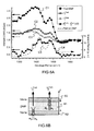
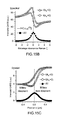
- the figure 9 illustrates experimental results obtained with the device of the figure 8A and a sample like that of the Figure 8B in which a thin layer of DMF (N, N-dimethylformamide) acts as a resonant medium between two glass strips (which here serve as a non-resonant medium).
- the wavelength of the pump beam is 730 nm, that of the Stokes excitation beam around 814 nm.
- the numerical aperture of the 807, 811 lenses of 0.6 in the air.
- Curve D1 clearly shows the distortion effect due to the non-resonant contribution of the resonant medium, while the difference ⁇ I Fwd is exactly superimposed on the Raman spectrum of the DMF (in dotted lines). It is thus possible to appreciate the ability of Dz-CARS to extract the Raman spectrum from the resonant medium without any distortion due to the non-resonant part of the resonant medium.
- the Figures 10A to 10D present numerical simulations obtained with the method according to the invention, on another type of sample.
- the images are calculated by taking as a sample a ball of 3 ⁇ m in diameter in an aqueous-type solvent (pump wavelength 730 nm, Stokes wavelength 814 nm, numerical aperture of the excitation objective 1.2 in FIG. water, numerical opening of 1.2 collection lens in water).
- the image is calculated in each case in a plane XZ of the ball corresponding to a longitudinal plane containing the direction of incidence of the excitation beams.
- the Figures 10A and 10B represent an image of the ball in conventional detection, that is to say that only the broadcast signal CARS in situation ⁇ is represented.
- the figure 11 illustrates an example of experimental setup for implementing the detection according to the invention according to a variant.
- the assembly is substantially identical to that of the figure 8A but the point detectors 816, 817 are replaced by matrix detectors 901, 902, for example of the CCD or CMOS type.
- matrix detectors 901, 902 for example of the CCD or CMOS type.
- the CARS broadcast signal is measured in a direction represented by the wave vector k , of coordinates k x , k y in the projection plane XY perpendicular to the main axis z
- the broadcast signal CARS is measured in a direction represented by the wave vector k of coordinates -k x , -k y in the projection plane XY
- the situation ⁇ corresponds to the generation of a broadcast signal CARS resulting from the interaction of the incident excitation beams with the sample
- the situation ⁇ corresponds to the generation of a diffused signal CARS resulting from the interaction of the excitation beams reflected with the sample.
- the figure 13 represents a sample comprising the resonant medium 131, for example a medium containing the medium to be analyzed, that is to say the medium of biological interest, and the non-resonant medium 132, typically a medium containing the solvent.
- Third- order nonlinear susceptibility is defined in the resonant medium 131 by a resonant term ⁇ (3) 1R and a non-resonant term ⁇ (3) 1NR .
- the non-resonant medium 132 it is defined by the non-resonant term ⁇ (3) 2NR .
- the pulsing pump excitation beams ⁇ p and the collinear pulse probe ⁇ s are incident on the sample in a focusing volume 135, intercepting an axial interface 133 of the 'sample.
- the light intensity of the nonlinear optical beam is analyzed in the space of the wave vectors.
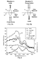
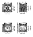
- FIGS. 14A to 14E represent by a series of diagrams the deviation of the broadcast signal CARS as a function of the relative position of the pump and Stokes beams incident with the interface.
- FIGS. 14A to 14E show the active volume CARS 135 (focussing spot of the pump and Stokes beams) which is displaced through a CARS object 140 (each sticker corresponds to a different position of the active volume in the object).
- the object CARS is considered as resonant while the medium surrounding the object is considered as non-resonant (it will be called in the following description "the solvent”). It appears that at the interfaces between the CARS object and the solvent, the broadcast signal CARS is affected by a deviation (or tilt).
- the figure 15A presents the results of a rigorous numerical calculation taking into account the vectorial nature of the pump and Stokes beams focused on an axial interface between a resonant medium 1 and a non-resonant medium 2 ( figure 13 ).
- the Figures 15B and 15C represent numerical simulations in which the diffused signal CARS is integrated respectively in the half-spaces (k x > 0) and (k x ⁇ 0) then the difference of the thus integrated signals is carried out.
- This difference exactly follows the Raman spectrum given by Im [ ⁇ (3) 1R ]. This demonstrates the relevance of the Dk-CARS approach for CARS spectroscopy without non-resonant noise.
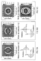
- the Figures 16A to 16C thus present 3 possible detection modes for the D-CARS microscopy associating the Dz-CARS approach and the Dk-CARS approach.
- a numerical simulation represents the image obtained for a 3 ⁇ m diameter ball in an aqueous-type solvent (pump wavelength 730 nm, Stokes wavelength 814 nm, numerical aperture of the objective excitement 1.2 in the water, numerical aperture of the 1.2 collection lens in the water).
- the figure 16A represents the XZ detection mode allowing detection at the interfaces perpendicular to the X axis and the interfaces perpendicular to the Z axis. For this, the difference of the CARS scattered signals is calculated respectively in the ⁇ and ⁇ situations by integrating the CARS signal.
- the difference in the luminous intensities integrated in the space (k y > 0) is calculated for different positions (problem ⁇ , Figure 7A ) and in space (k y ⁇ 0) (problem ⁇ , Figure 7B ).
- the figure 16C represents the XYZ detection mode.
- the image is calculated by making the two-by-two difference of the luminous intensities I ⁇ (k x , k y ) and I ⁇ (-k x , -k y ) measured in two directions k (k x , k y, k z ) and k (-k x , -k y , k z ) respectively, in the situations ⁇ and ⁇ , the directions being contained in the angular cone whose opening angle is defined by the digital opening of the collection of the broadcast signal CARS (eg 1.2 in water)
- the coordinates of the wave vectors k and k "are expressed in the reference frames of the excitation beams specific to situations ⁇ and ⁇ respectively.
- Angular scanning means can be provided for the excitation beams, in particular for microscopy applications.
- a reflecting mirror of the spherical excitation beams 813 it will be possible to choose a reflecting mirror of the spherical excitation beams 813.
- a calibration of the cameras in solution is also possible in order to identify, in each of the situations ⁇ and ⁇ , and for each scanning angle, the direction of the excitation beams with respect to which the deflection of the broadcast signal CARS will be measured.
- the Dz-CARS or D-CARS detection has been described by means of the examples of implementation of the Figures 8A and 11 in a two-color application, using two spectrally thin laser sources.
- a source of emission of the spectrally broad Stokes beam generated for example by a femtosecond pulse or by a supercontinuum generated by an optical fiber or another dispersive medium.
- the pump signal remains thin spectrally.
- it will be possible to acquire a Raman spectrum in a single pulse for example using two slit spectrometers or a single spectrometer equipped with a CCD camera in which the two signals detected in the two situations ⁇ and ⁇ .
- three associated pulse wavelengths ⁇ 1 , ⁇ 2 and ⁇ 3 are used to generate a CARS signal at the pulsation ⁇ 1 - ⁇ 2 + ⁇ 3 .
- the signal CARS can be rendered without non-resonant noise by detecting the signals at the pulsation ⁇ 1 - ⁇ 2 + ⁇ 3 in the situations ( ⁇ or ⁇ ) and making their difference.
- the detection method has been described in the case of the CARS diffusion, it is equally applicable to other non-linear process, the 2 nd or 3 rd order for both spectroscopy applications or for detection microscopy applications at axial interfaces, thus revealing interfaces between resonant and non-resonant media.
- an analysis of the non-linear optical signal resulting from the interaction of one or more excitation beams with a sample having an interface between a resonant medium and a non-resonant medium is carried out.
- This spatial analysis makes it possible either to reveal the interface between the resonant medium and the non-resonant medium, or to characterize a spectrum of the resonant medium.
- a resonant third harmonic generation process in which the resonance is an electronic resonance, by exciting with a single pump excitation beam, of a pulsation ⁇ p , a sample comprising an interface between a resonant medium and a non-resonant medium.
- a picosecond or femtosecond laser source of Ti: Saphir, Nd: glass, Ytterbium or Erbium doped fiber laser type is used.
- a resonant four-wave mixing process in which the resonance is an electronic resonance, by exciting with a single pump excitation beam, of a pulsation ⁇ p , a sample comprising an interface between a resonant medium and a non-resonant medium.
- a picosecond or femtosecond laser source of Ti: Saphir, Nd: glass, Ytterbium or Erbium doped fiber laser type is used.
- the second harmonic can be excite resonant beam with a single pump, or it may make the sum frequency with a pump beam and a probe beam (non-linear effect of the 2 nd order).
- the detection device and the method according to the invention comprise various variants, modifications and improvements which will be apparent to those skilled in the art, being understood that these various variants, modifications and improvements are within the scope of the invention, as defined by the claims that follow.
Landscapes
- Physics & Mathematics (AREA)
- Spectroscopy & Molecular Physics (AREA)
- Health & Medical Sciences (AREA)
- General Physics & Mathematics (AREA)
- Chemical & Material Sciences (AREA)
- Life Sciences & Earth Sciences (AREA)
- Nuclear Medicine, Radiotherapy & Molecular Imaging (AREA)
- Analytical Chemistry (AREA)
- Biochemistry (AREA)
- General Health & Medical Sciences (AREA)
- Immunology (AREA)
- Pathology (AREA)
- Investigating, Analyzing Materials By Fluorescence Or Luminescence (AREA)
Applications Claiming Priority (2)
| Application Number | Priority Date | Filing Date | Title |
|---|---|---|---|
| FR1000245A FR2955664B1 (fr) | 2010-01-22 | 2010-01-22 | Methode pour la detection d'un signal optique non lineaire resonant et dispositif pour la mise en oeuvre de ladite methode |
| PCT/EP2011/050619 WO2011089118A1 (fr) | 2010-01-22 | 2011-01-18 | Methode pour la detection d'un signal optique non lineaire resonant et dispositif pour la mise en oeuvre de ladite methode |
Publications (2)
| Publication Number | Publication Date |
|---|---|
| EP2526407A1 EP2526407A1 (fr) | 2012-11-28 |
| EP2526407B1 true EP2526407B1 (fr) | 2013-11-27 |
Family
ID=42635573
Family Applications (1)
| Application Number | Title | Priority Date | Filing Date |
|---|---|---|---|
| EP11703160.9A Not-in-force EP2526407B1 (fr) | 2010-01-22 | 2011-01-18 | Méthode pour la détection d'un signal optique non linéaire résonant et dispositif pour la mise en oeuvre de ladite méthode |
Country Status (5)
| Country | Link |
|---|---|
| US (1) | US9097674B2 (enExample) |
| EP (1) | EP2526407B1 (enExample) |
| JP (1) | JP5536908B2 (enExample) |
| FR (1) | FR2955664B1 (enExample) |
| WO (1) | WO2011089118A1 (enExample) |
Families Citing this family (5)
| Publication number | Priority date | Publication date | Assignee | Title |
|---|---|---|---|---|
| FR3003949B1 (fr) * | 2013-03-26 | 2015-05-01 | Univ Aix Marseille | Dispositif et methode de detection raman stimulee. |
| US10071141B2 (en) | 2015-05-08 | 2018-09-11 | Spectral Platforms, Inc. | Albumin-based non-covalent complexes and methods of use thereof |
| EP3474001B1 (en) * | 2016-06-17 | 2021-11-17 | Saitama Medical University | Test object visualizing device |
| US11105747B2 (en) * | 2017-03-20 | 2021-08-31 | Spectral Platforms, Inc. | Spectroscopic methods to detect and characterize microorganisms |
| JP7568210B2 (ja) * | 2020-05-22 | 2024-10-16 | 国立大学法人山梨大学 | 分析システム及び分析方法 |
Family Cites Families (10)
| Publication number | Priority date | Publication date | Assignee | Title |
|---|---|---|---|---|
| US3516744A (en) * | 1966-05-20 | 1970-06-23 | Perkin Elmer Corp | Sampling arrangement for laser-raman systems |
| US5929981A (en) * | 1996-06-18 | 1999-07-27 | Ohmeda Inc. | System for monitoring contamination of optical elements in a Raman gas analyzer |
| GB2349033B (en) * | 1998-01-27 | 2002-06-26 | Wisconsin Alumni Res Found | Signal enhancement for fluorescence microscopy |
| US6614532B1 (en) * | 2000-04-28 | 2003-09-02 | Mcgill University | Apparatus and method for light profile microscopy |
| DE10100247A1 (de) * | 2001-01-05 | 2002-07-11 | Leica Microsystems | Interferenzmikroskop und Verfahren zum Betrieb eines Interferenzmikroskops |
| US20040142484A1 (en) * | 2002-09-30 | 2004-07-22 | Intel Corporation | Spectroscopic analysis system and method |
| US7586618B2 (en) * | 2005-02-28 | 2009-09-08 | The Board Of Trustees Of The University Of Illinois | Distinguishing non-resonant four-wave-mixing noise in coherent stokes and anti-stokes Raman scattering |
| US7573577B2 (en) * | 2005-10-21 | 2009-08-11 | Southwest Research Institute | Spatial heterodyne wide-field Coherent Anti-Stokes Raman spectromicroscopy |
| US20100232459A1 (en) * | 2006-05-15 | 2010-09-16 | Mamoru Hashimoto | Pulse Laser Light Timing Adjusting Device, Adjusting Method, and Optical Microscope |
| WO2009149733A1 (en) * | 2008-06-13 | 2009-12-17 | Embl Heidelberg | Next generation flow cytometer sorter |
-
2010
- 2010-01-22 FR FR1000245A patent/FR2955664B1/fr not_active Expired - Fee Related
-
2011
- 2011-01-18 JP JP2012549333A patent/JP5536908B2/ja not_active Expired - Fee Related
- 2011-01-18 WO PCT/EP2011/050619 patent/WO2011089118A1/fr not_active Ceased
- 2011-01-18 US US13/574,508 patent/US9097674B2/en not_active Expired - Fee Related
- 2011-01-18 EP EP11703160.9A patent/EP2526407B1/fr not_active Not-in-force
Also Published As
| Publication number | Publication date |
|---|---|
| EP2526407A1 (fr) | 2012-11-28 |
| WO2011089118A1 (fr) | 2011-07-28 |
| FR2955664A1 (fr) | 2011-07-29 |
| US20130038871A1 (en) | 2013-02-14 |
| US9097674B2 (en) | 2015-08-04 |
| JP2013517490A (ja) | 2013-05-16 |
| FR2955664B1 (fr) | 2012-02-10 |
| JP5536908B2 (ja) | 2014-07-02 |
Similar Documents
| Publication | Publication Date | Title |
|---|---|---|
| EP2526408B1 (fr) | Methode pour la detection d'un signal optique non lineaire resonant et dispositif pour la mise en oeuvre de ladite methode | |
| EP2979080B1 (fr) | Dispositif et methode de detection raman stimulee | |
| EP2522969A2 (en) | Nonlinear raman spectroscopic apparatus comprising single mode fiber for generating Stokes beam | |
| EP3488505B1 (fr) | Système et procédé de spectrométrie acoustique résonante | |
| FR2530024A1 (fr) | Microsonde a effet raman a laser | |
| WO2014125729A1 (ja) | 測定装置及び測定方法 | |
| EP2526407B1 (fr) | Méthode pour la détection d'un signal optique non linéaire résonant et dispositif pour la mise en oeuvre de ladite méthode | |
| WO2016097191A1 (fr) | Dispositif de transport et de contrôle d'impulsions lumineuses pour l'imagerie endo-microscopique sans lentille | |
| CN110579462B (zh) | 一种基于高重频飞秒激光的时间分辨宽谱cars光谱成像装置 | |
| Coluccelli et al. | Broadband Fourier-transform coherent Raman spectroscopy with an ytterbium fiber laser | |
| US20070252978A1 (en) | Method and Apparatus for Optical Spectroscopy | |
| EP0426571A1 (fr) | Procédé d'analyse spectroscopique ponctuelle de la lumière diffractée ou absorbée par une substance placée dans un champ proche | |
| EP3775851B1 (en) | Method and apparatus for simultaneous nonlinear excitation and detection of different chromophores across a wide spectral range using ultra-broadband light pulses and time-resolved detection | |
| CN116380856A (zh) | 瞬态受激拉曼激发荧光光谱方法与系统 | |
| JP3816306B2 (ja) | 超高速時間分解蛍光分光方法 | |
| EP2488854B1 (fr) | Procede et systeme d'imagerie par fonctionnalisation du substrat | |
| EP3919893A1 (fr) | Procédés et dispositifs de détection d'un signal de diffusion raman stimulée (srs) dans un échantillon | |
| WO2017148858A1 (fr) | Dispositif optique d'excitation pour générer des processus raman stimulés, ensemble de mesure de processus raman stimulés et procédé d'excitation optique pour générer des processus raman stimulés | |
| EP1419415B1 (fr) | Source laser ultrabreve compacte a spectre large controle | |
| WO2003010523A1 (fr) | Dispositif et procede de mesure d'un echantillon par spectroscopie par correlation | |
| EP3423882B1 (fr) | Miscroscopie optique non-linéaire quantitative | |
| McNamara et al. | Hyperspectral imaging system with switchable spontaneous Raman spectroscopy and broadband CARS | |
| FR3146214A1 (fr) | Lame optique destinée à la microscopie par réflexion totale interne, dispositif de microscopie par réflexion totale interne comportant une telle lame et procédé de fabrication d’une telle lame | |
| FR2998967A1 (fr) | Appareil et methode de spectroscopie |
Legal Events
| Date | Code | Title | Description |
|---|---|---|---|
| PUAI | Public reference made under article 153(3) epc to a published international application that has entered the european phase |
Free format text: ORIGINAL CODE: 0009012 |
|
| 17P | Request for examination filed |
Effective date: 20120817 |
|
| AK | Designated contracting states |
Kind code of ref document: A1 Designated state(s): AL AT BE BG CH CY CZ DE DK EE ES FI FR GB GR HR HU IE IS IT LI LT LU LV MC MK MT NL NO PL PT RO RS SE SI SK SM TR |
|
| DAX | Request for extension of the european patent (deleted) | ||
| GRAP | Despatch of communication of intention to grant a patent |
Free format text: ORIGINAL CODE: EPIDOSNIGR1 |
|
| INTG | Intention to grant announced |
Effective date: 20130614 |
|
| GRAS | Grant fee paid |
Free format text: ORIGINAL CODE: EPIDOSNIGR3 |
|
| GRAA | (expected) grant |
Free format text: ORIGINAL CODE: 0009210 |
|
| AK | Designated contracting states |
Kind code of ref document: B1 Designated state(s): AL AT BE BG CH CY CZ DE DK EE ES FI FR GB GR HR HU IE IS IT LI LT LU LV MC MK MT NL NO PL PT RO RS SE SI SK SM TR |
|
| REG | Reference to a national code |
Ref country code: GB Ref legal event code: FG4D Free format text: NOT ENGLISH |
|
| REG | Reference to a national code |
Ref country code: CH Ref legal event code: EP |
|
| REG | Reference to a national code |
Ref country code: AT Ref legal event code: REF Ref document number: 642909 Country of ref document: AT Kind code of ref document: T Effective date: 20131215 |
|
| REG | Reference to a national code |
Ref country code: IE Ref legal event code: FG4D Free format text: LANGUAGE OF EP DOCUMENT: FRENCH |
|
| REG | Reference to a national code |
Ref country code: DE Ref legal event code: R096 Ref document number: 602011003964 Country of ref document: DE Effective date: 20140123 |
|
| REG | Reference to a national code |
Ref country code: NL Ref legal event code: VDEP Effective date: 20131127 |
|
| REG | Reference to a national code |
Ref country code: AT Ref legal event code: MK05 Ref document number: 642909 Country of ref document: AT Kind code of ref document: T Effective date: 20131127 |
|
| REG | Reference to a national code |
Ref country code: LT Ref legal event code: MG4D |
|
| PG25 | Lapsed in a contracting state [announced via postgrant information from national office to epo] |
Ref country code: FI Free format text: LAPSE BECAUSE OF FAILURE TO SUBMIT A TRANSLATION OF THE DESCRIPTION OR TO PAY THE FEE WITHIN THE PRESCRIBED TIME-LIMIT Effective date: 20131127 Ref country code: NL Free format text: LAPSE BECAUSE OF FAILURE TO SUBMIT A TRANSLATION OF THE DESCRIPTION OR TO PAY THE FEE WITHIN THE PRESCRIBED TIME-LIMIT Effective date: 20131127 Ref country code: HR Free format text: LAPSE BECAUSE OF FAILURE TO SUBMIT A TRANSLATION OF THE DESCRIPTION OR TO PAY THE FEE WITHIN THE PRESCRIBED TIME-LIMIT Effective date: 20131127 Ref country code: LT Free format text: LAPSE BECAUSE OF FAILURE TO SUBMIT A TRANSLATION OF THE DESCRIPTION OR TO PAY THE FEE WITHIN THE PRESCRIBED TIME-LIMIT Effective date: 20131127 Ref country code: IS Free format text: LAPSE BECAUSE OF FAILURE TO SUBMIT A TRANSLATION OF THE DESCRIPTION OR TO PAY THE FEE WITHIN THE PRESCRIBED TIME-LIMIT Effective date: 20140327 Ref country code: NO Free format text: LAPSE BECAUSE OF FAILURE TO SUBMIT A TRANSLATION OF THE DESCRIPTION OR TO PAY THE FEE WITHIN THE PRESCRIBED TIME-LIMIT Effective date: 20140227 Ref country code: SE Free format text: LAPSE BECAUSE OF FAILURE TO SUBMIT A TRANSLATION OF THE DESCRIPTION OR TO PAY THE FEE WITHIN THE PRESCRIBED TIME-LIMIT Effective date: 20131127 |
|
| PG25 | Lapsed in a contracting state [announced via postgrant information from national office to epo] |
Ref country code: RS Free format text: LAPSE BECAUSE OF FAILURE TO SUBMIT A TRANSLATION OF THE DESCRIPTION OR TO PAY THE FEE WITHIN THE PRESCRIBED TIME-LIMIT Effective date: 20131127 Ref country code: CY Free format text: LAPSE BECAUSE OF FAILURE TO SUBMIT A TRANSLATION OF THE DESCRIPTION OR TO PAY THE FEE WITHIN THE PRESCRIBED TIME-LIMIT Effective date: 20131127 Ref country code: ES Free format text: LAPSE BECAUSE OF FAILURE TO SUBMIT A TRANSLATION OF THE DESCRIPTION OR TO PAY THE FEE WITHIN THE PRESCRIBED TIME-LIMIT Effective date: 20131127 Ref country code: AT Free format text: LAPSE BECAUSE OF FAILURE TO SUBMIT A TRANSLATION OF THE DESCRIPTION OR TO PAY THE FEE WITHIN THE PRESCRIBED TIME-LIMIT Effective date: 20131127 Ref country code: LV Free format text: LAPSE BECAUSE OF FAILURE TO SUBMIT A TRANSLATION OF THE DESCRIPTION OR TO PAY THE FEE WITHIN THE PRESCRIBED TIME-LIMIT Effective date: 20131127 |
|
| PG25 | Lapsed in a contracting state [announced via postgrant information from national office to epo] |
Ref country code: PT Free format text: LAPSE BECAUSE OF FAILURE TO SUBMIT A TRANSLATION OF THE DESCRIPTION OR TO PAY THE FEE WITHIN THE PRESCRIBED TIME-LIMIT Effective date: 20140327 |
|
| BERE | Be: lapsed |
Owner name: CENTRE NATIONAL DE LA RECHERCHE SCIENTIFIQUE CNRS Effective date: 20140131 |
|
| PG25 | Lapsed in a contracting state [announced via postgrant information from national office to epo] |
Ref country code: EE Free format text: LAPSE BECAUSE OF FAILURE TO SUBMIT A TRANSLATION OF THE DESCRIPTION OR TO PAY THE FEE WITHIN THE PRESCRIBED TIME-LIMIT Effective date: 20131127 |
|
| REG | Reference to a national code |
Ref country code: DE Ref legal event code: R097 Ref document number: 602011003964 Country of ref document: DE |
|
| PG25 | Lapsed in a contracting state [announced via postgrant information from national office to epo] |
Ref country code: RO Free format text: LAPSE BECAUSE OF FAILURE TO SUBMIT A TRANSLATION OF THE DESCRIPTION OR TO PAY THE FEE WITHIN THE PRESCRIBED TIME-LIMIT Effective date: 20131127 Ref country code: LU Free format text: LAPSE BECAUSE OF FAILURE TO SUBMIT A TRANSLATION OF THE DESCRIPTION OR TO PAY THE FEE WITHIN THE PRESCRIBED TIME-LIMIT Effective date: 20140118 Ref country code: SK Free format text: LAPSE BECAUSE OF FAILURE TO SUBMIT A TRANSLATION OF THE DESCRIPTION OR TO PAY THE FEE WITHIN THE PRESCRIBED TIME-LIMIT Effective date: 20131127 Ref country code: PL Free format text: LAPSE BECAUSE OF FAILURE TO SUBMIT A TRANSLATION OF THE DESCRIPTION OR TO PAY THE FEE WITHIN THE PRESCRIBED TIME-LIMIT Effective date: 20131127 Ref country code: CZ Free format text: LAPSE BECAUSE OF FAILURE TO SUBMIT A TRANSLATION OF THE DESCRIPTION OR TO PAY THE FEE WITHIN THE PRESCRIBED TIME-LIMIT Effective date: 20131127 |
|
| REG | Reference to a national code |
Ref country code: CH Ref legal event code: PL |
|
| PG25 | Lapsed in a contracting state [announced via postgrant information from national office to epo] |
Ref country code: DK Free format text: LAPSE BECAUSE OF FAILURE TO SUBMIT A TRANSLATION OF THE DESCRIPTION OR TO PAY THE FEE WITHIN THE PRESCRIBED TIME-LIMIT Effective date: 20131127 |
|
| PLBE | No opposition filed within time limit |
Free format text: ORIGINAL CODE: 0009261 |
|
| STAA | Information on the status of an ep patent application or granted ep patent |
Free format text: STATUS: NO OPPOSITION FILED WITHIN TIME LIMIT |
|
| PG25 | Lapsed in a contracting state [announced via postgrant information from national office to epo] |
Ref country code: CH Free format text: LAPSE BECAUSE OF NON-PAYMENT OF DUE FEES Effective date: 20140131 Ref country code: LI Free format text: LAPSE BECAUSE OF NON-PAYMENT OF DUE FEES Effective date: 20140131 |
|
| 26N | No opposition filed |
Effective date: 20140828 |
|
| REG | Reference to a national code |
Ref country code: IE Ref legal event code: MM4A |
|
| REG | Reference to a national code |
Ref country code: DE Ref legal event code: R097 Ref document number: 602011003964 Country of ref document: DE Effective date: 20140828 |
|
| PG25 | Lapsed in a contracting state [announced via postgrant information from national office to epo] |
Ref country code: BE Free format text: LAPSE BECAUSE OF NON-PAYMENT OF DUE FEES Effective date: 20140131 Ref country code: IE Free format text: LAPSE BECAUSE OF NON-PAYMENT OF DUE FEES Effective date: 20140118 |
|
| PG25 | Lapsed in a contracting state [announced via postgrant information from national office to epo] |
Ref country code: SI Free format text: LAPSE BECAUSE OF FAILURE TO SUBMIT A TRANSLATION OF THE DESCRIPTION OR TO PAY THE FEE WITHIN THE PRESCRIBED TIME-LIMIT Effective date: 20131127 |
|
| PG25 | Lapsed in a contracting state [announced via postgrant information from national office to epo] |
Ref country code: MC Free format text: LAPSE BECAUSE OF FAILURE TO SUBMIT A TRANSLATION OF THE DESCRIPTION OR TO PAY THE FEE WITHIN THE PRESCRIBED TIME-LIMIT Effective date: 20131127 |
|
| REG | Reference to a national code |
Ref country code: FR Ref legal event code: PLFP Year of fee payment: 6 |
|
| PG25 | Lapsed in a contracting state [announced via postgrant information from national office to epo] |
Ref country code: MT Free format text: LAPSE BECAUSE OF FAILURE TO SUBMIT A TRANSLATION OF THE DESCRIPTION OR TO PAY THE FEE WITHIN THE PRESCRIBED TIME-LIMIT Effective date: 20131127 |
|
| PG25 | Lapsed in a contracting state [announced via postgrant information from national office to epo] |
Ref country code: SM Free format text: LAPSE BECAUSE OF FAILURE TO SUBMIT A TRANSLATION OF THE DESCRIPTION OR TO PAY THE FEE WITHIN THE PRESCRIBED TIME-LIMIT Effective date: 20131127 |
|
| PG25 | Lapsed in a contracting state [announced via postgrant information from national office to epo] |
Ref country code: IT Free format text: LAPSE BECAUSE OF FAILURE TO SUBMIT A TRANSLATION OF THE DESCRIPTION OR TO PAY THE FEE WITHIN THE PRESCRIBED TIME-LIMIT Effective date: 20131127 Ref country code: BG Free format text: LAPSE BECAUSE OF FAILURE TO SUBMIT A TRANSLATION OF THE DESCRIPTION OR TO PAY THE FEE WITHIN THE PRESCRIBED TIME-LIMIT Effective date: 20131127 Ref country code: GR Free format text: LAPSE BECAUSE OF FAILURE TO SUBMIT A TRANSLATION OF THE DESCRIPTION OR TO PAY THE FEE WITHIN THE PRESCRIBED TIME-LIMIT Effective date: 20140228 |
|
| PG25 | Lapsed in a contracting state [announced via postgrant information from national office to epo] |
Ref country code: HU Free format text: LAPSE BECAUSE OF FAILURE TO SUBMIT A TRANSLATION OF THE DESCRIPTION OR TO PAY THE FEE WITHIN THE PRESCRIBED TIME-LIMIT; INVALID AB INITIO Effective date: 20110118 Ref country code: TR Free format text: LAPSE BECAUSE OF FAILURE TO SUBMIT A TRANSLATION OF THE DESCRIPTION OR TO PAY THE FEE WITHIN THE PRESCRIBED TIME-LIMIT Effective date: 20131127 |
|
| REG | Reference to a national code |
Ref country code: FR Ref legal event code: PLFP Year of fee payment: 7 |
|
| REG | Reference to a national code |
Ref country code: FR Ref legal event code: PLFP Year of fee payment: 8 |
|
| PG25 | Lapsed in a contracting state [announced via postgrant information from national office to epo] |
Ref country code: MK Free format text: LAPSE BECAUSE OF FAILURE TO SUBMIT A TRANSLATION OF THE DESCRIPTION OR TO PAY THE FEE WITHIN THE PRESCRIBED TIME-LIMIT Effective date: 20131127 |
|
| PG25 | Lapsed in a contracting state [announced via postgrant information from national office to epo] |
Ref country code: AL Free format text: LAPSE BECAUSE OF FAILURE TO SUBMIT A TRANSLATION OF THE DESCRIPTION OR TO PAY THE FEE WITHIN THE PRESCRIBED TIME-LIMIT Effective date: 20131127 |
|
| REG | Reference to a national code |
Ref country code: DE Ref legal event code: R082 Ref document number: 602011003964 Country of ref document: DE Representative=s name: DOMPATENT VON KREISLER SELTING WERNER - PARTNE, DE |
|
| PGFP | Annual fee paid to national office [announced via postgrant information from national office to epo] |
Ref country code: FR Payment date: 20210128 Year of fee payment: 11 |
|
| PGFP | Annual fee paid to national office [announced via postgrant information from national office to epo] |
Ref country code: GB Payment date: 20210118 Year of fee payment: 11 Ref country code: DE Payment date: 20210112 Year of fee payment: 11 |
|
| REG | Reference to a national code |
Ref country code: DE Ref legal event code: R119 Ref document number: 602011003964 Country of ref document: DE |
|
| GBPC | Gb: european patent ceased through non-payment of renewal fee |
Effective date: 20220118 |
|
| PG25 | Lapsed in a contracting state [announced via postgrant information from national office to epo] |
Ref country code: GB Free format text: LAPSE BECAUSE OF NON-PAYMENT OF DUE FEES Effective date: 20220118 Ref country code: DE Free format text: LAPSE BECAUSE OF NON-PAYMENT OF DUE FEES Effective date: 20220802 |
|
| PG25 | Lapsed in a contracting state [announced via postgrant information from national office to epo] |
Ref country code: FR Free format text: LAPSE BECAUSE OF NON-PAYMENT OF DUE FEES Effective date: 20220131 |