EP2526007B1 - Vehicle with covering module, covering module and assembly set - Google Patents
Vehicle with covering module, covering module and assembly set Download PDFInfo
- Publication number
- EP2526007B1 EP2526007B1 EP11709024.1A EP11709024A EP2526007B1 EP 2526007 B1 EP2526007 B1 EP 2526007B1 EP 11709024 A EP11709024 A EP 11709024A EP 2526007 B1 EP2526007 B1 EP 2526007B1
- Authority
- EP
- European Patent Office
- Prior art keywords
- lining
- lining module
- side walls
- base element
- module
- Prior art date
- Legal status (The legal status is an assumption and is not a legal conclusion. Google has not performed a legal analysis and makes no representation as to the accuracy of the status listed.)
- Active
Links
- 239000002131 composite material Substances 0.000 claims description 17
- 239000011810 insulating material Substances 0.000 claims description 4
- 229910052751 metal Inorganic materials 0.000 claims description 3
- 239000002184 metal Substances 0.000 claims description 3
- 229910052782 aluminium Inorganic materials 0.000 claims description 2
- XAGFODPZIPBFFR-UHFFFAOYSA-N aluminium Chemical compound [Al] XAGFODPZIPBFFR-UHFFFAOYSA-N 0.000 claims description 2
- 229910001220 stainless steel Inorganic materials 0.000 claims description 2
- 239000010935 stainless steel Substances 0.000 claims description 2
- 239000011796 hollow space material Substances 0.000 claims 4
- 229910003460 diamond Inorganic materials 0.000 claims 1
- 239000010432 diamond Substances 0.000 claims 1
- 239000011120 plywood Substances 0.000 claims 1
- 239000002023 wood Substances 0.000 claims 1
- 238000010276 construction Methods 0.000 description 3
- 239000000463 material Substances 0.000 description 3
- 230000001413 cellular effect Effects 0.000 description 2
- 238000006073 displacement reaction Methods 0.000 description 2
- 238000004519 manufacturing process Methods 0.000 description 2
- 238000012986 modification Methods 0.000 description 2
- 230000004048 modification Effects 0.000 description 2
- 238000007650 screen-printing Methods 0.000 description 2
- 210000003850 cellular structure Anatomy 0.000 description 1
- 238000005260 corrosion Methods 0.000 description 1
- 230000007797 corrosion Effects 0.000 description 1
- 230000001419 dependent effect Effects 0.000 description 1
- 238000009434 installation Methods 0.000 description 1
- 239000007788 liquid Substances 0.000 description 1
- 238000000034 method Methods 0.000 description 1
- 230000000149 penetrating effect Effects 0.000 description 1
- 230000002787 reinforcement Effects 0.000 description 1
- 230000003014 reinforcing effect Effects 0.000 description 1
- 230000000284 resting effect Effects 0.000 description 1
Images


Classifications
-
- B—PERFORMING OPERATIONS; TRANSPORTING
- B62—LAND VEHICLES FOR TRAVELLING OTHERWISE THAN ON RAILS
- B62D—MOTOR VEHICLES; TRAILERS
- B62D25/00—Superstructure or monocoque structure sub-units; Parts or details thereof not otherwise provided for
- B62D25/20—Floors or bottom sub-units
- B62D25/2054—Load carrying floors for commercial vehicles
-
- B—PERFORMING OPERATIONS; TRANSPORTING
- B62—LAND VEHICLES FOR TRAVELLING OTHERWISE THAN ON RAILS
- B62D—MOTOR VEHICLES; TRAILERS
- B62D33/00—Superstructures for load-carrying vehicles
- B62D33/04—Enclosed load compartments ; Frameworks for movable panels, tarpaulins or side curtains
-
- B—PERFORMING OPERATIONS; TRANSPORTING
- B62—LAND VEHICLES FOR TRAVELLING OTHERWISE THAN ON RAILS
- B62D—MOTOR VEHICLES; TRAILERS
- B62D33/00—Superstructures for load-carrying vehicles
-
- B—PERFORMING OPERATIONS; TRANSPORTING
- B62—LAND VEHICLES FOR TRAVELLING OTHERWISE THAN ON RAILS
- B62D—MOTOR VEHICLES; TRAILERS
- B62D33/00—Superstructures for load-carrying vehicles
- B62D33/02—Platforms; Open load compartments
-
- B—PERFORMING OPERATIONS; TRANSPORTING
- B62—LAND VEHICLES FOR TRAVELLING OTHERWISE THAN ON RAILS
- B62D—MOTOR VEHICLES; TRAILERS
- B62D33/00—Superstructures for load-carrying vehicles
- B62D33/04—Enclosed load compartments ; Frameworks for movable panels, tarpaulins or side curtains
- B62D33/044—Enclosed load compartments ; Frameworks for movable panels, tarpaulins or side curtains built up with profiles of constant elongated shape, e.g. extruded, mechanically interconnected by coupling members, e.g. by clamping, riveting or bolting
-
- B—PERFORMING OPERATIONS; TRANSPORTING
- B62—LAND VEHICLES FOR TRAVELLING OTHERWISE THAN ON RAILS
- B62D—MOTOR VEHICLES; TRAILERS
- B62D33/00—Superstructures for load-carrying vehicles
- B62D33/04—Enclosed load compartments ; Frameworks for movable panels, tarpaulins or side curtains
- B62D33/048—Enclosed load compartments ; Frameworks for movable panels, tarpaulins or side curtains for refrigerated goods vehicles
Definitions
- the present invention relates to a motor vehicle with at least one lining module, a lining module and a composite group with at least two lining modules.
- a floor platform for a chassis of trucks, in particular semi-trailers, for container floors, ship decks and the like which comprises a supporting structure and a cover that closes the supporting structure at least on one flat side.
- the supporting structure consists at least partially of a honeycomb structure which is made up of one another crossing web plates and consists of cover plates connected to part of the edges of the web plates and enclosing and stiffening the honeycomb structure, the latter at least partially serving as a cover.
- the EP 1 445 178 A1 discloses a floor for a vehicle for carrying goods, such as a truck, an industrial vehicle and the like, which has a plate-like shape includes flat structure, which is designed to be fastened on longitudinal elements of the main frame of the vehicle.
- the plate-shaped flat structure comprises a frame which forms at least part of the main frame after assembly, and a plate which comprises a plurality of layers, a layer having a cellular basic structure being arranged between an upper and a lower layer. Both have a limited thickness compared to that of the basic cellular structure.
- Transversal rod-shaped inserts, which are part of the frame and form cross members of the main frame after assembly, are embedded in the thickness of the cellular basic structure, which results in a composite, structurally one-piece and self-supporting floor.
- a commercial vehicle with a vehicle frame and a loading space which has a floor, the floor comprising at least one insert element which is arranged in a floor mount of the vehicle frame.
- the shelf element has at least a first layer to form a walkable top and a second layer with a honeycomb structure.
- the US 5 791 714 A discloses an end unit for use on vehicles with modular floors, such as truck beds, trailers and the like.
- the end unit includes a load-bearing section with an integrated reinforcing rib that extends along the edge of the load-bearing section that stiffens the load-bearing section against point loads and impact loads.
- the US 4,267,679 A discloses an insulating panel wall construction having a plurality of hollow insulated construction panels.
- the GB 2 158 931 A describes side walls of an insulated vehicle body, which consists of several panels.
- the EP 0 458 113 A1 discloses body components on which separate fasteners are provided to securely attach a lighting pole or the like.
- a motor vehicle has at least one lining module, which at least part of a Covering the loading area or at least a part of a wall surface of the motor vehicle and which comprises at least one base element, at least two side walls and at least one cover plate, the base element being provided for at least partial application of the lining module on a base, the side walls at least on two opposite end sections of the base element are connected to it and the cover plate is held on edge sections of the side walls facing away from the base element, the base element, side walls and cover plate enclosing at least one cavity.
- a composite group according to the present invention comprises at least two such lining modules connected to one another.
- lining modules and composite groups in contrast to known motor vehicles, lining modules and composite groups, in accordance with the present invention, in the case of the lining module, structures such as T-, double-T-beams, cross members, web plates or honeycomb elements are dispensed with. Instead, the lining module has a cavity that can be used in a variety of ways. So in the same line, Units and control units can be accommodated in an installation channel in a position protected from the outside, which is not possible with known lining modules due to the various supporting structures. In the interior of the lining module, however, a clean and protected cable routing is possible.
- the motor vehicle, the lining module and the composite group according to the present invention are more resistant to known motor vehicles, lining modules and composite groups, since the latter give rise to manifold angles, corners, edges and smaller spaces as a result of the supporting structures, which have proven to be extremely susceptible to corrosion.
- lining modules can be used very generally both for lining or covering or covering floors or storage areas and also for covering, in particular, vertical walls.
- the underlay can be, for example, a floor surface or a frame and in particular a vehicle frame, or a wall surface or one or more supports.
- the lining module is intended for lining a storage area and the base element is closed at the bottom, or if the base element is recessed like a trough and / or the cavity on sides not enclosed by the base element, the side walls and the cover plate is at least partially closed, in In the event of the transport of problematic transport goods, unintentionally released liquids, dusts or other bulk goods are caught in the cavity, thereby preventing them from penetrating into the ground.
- the dimensions of the lining module are limited depending on the materials used for its manufacture, but it is possible to position several of the lining modules next to one another in any orientation for lining larger areas.
- a motor vehicle according to the invention can have a plurality of the lining modules with areas which are small in comparison to the area of the area to be lined, instead of providing a few large-area lining modules or even just one lining module with supporting structures for floor areas, as in known vehicles.
- the lining modules can be manufactured in a wide variety of heights and sizes, as well as from a wide variety of materials and with a wide range of strengths, both mechanically and manually.
- the base element and / or the side walls can be shaped in any way in general. At least one of the side walls can be bent as desired. However, the side walls are preferably essentially flat or plate-like.
- the base element and the side walls are designed as a one-piece shaped profile.
- a shaped profile is characterized by a simple and inexpensive method of manufacture and by a particularly high stability.
- the cover plate in principle, in the lining module, can be held detachably or non-detachably on the side walls.
- the cover plate can be glued, riveted, nailed or welded to the edge sections of the side walls.
- a detachable bracket can be screwed, mortised, Brackets or locking devices can be executed.
- the edge sections of the side walls can be angled and serve as a contact or support surface for the cover plate.
- the edge sections can have groove-like depressions into which the cover plate can be inserted with respective edge sections, or rail-like projections can be formed on the edge sections of the side walls, onto which a cover plate provided with corresponding groove-like depressions can be pushed.
- Removable cover plates can advantageously be exchanged quickly and easily without having to replace the entire lining module.
- the cover plate can easily be replaced by a food-safe cover plate if the storage area is to be converted to storing food.
- the lining module can be easily adapted to a wide variety of requirements that are placed on the properties of the materials that come into contact with the stored goods.
- the cover plate can be of any type depending on the requirements.
- the cover plate is preferably or comprises at least one wooden plate and / or at least one screen printing plate and / or at least one metal plate and / or at least one stainless steel plate and / or at least one aluminum plate and / or at least one corrugated plate and / or at least one tear plate. Furthermore, the cover plate can have at least one recess.
- the lining module particularly preferably has at least one connecting device for releasably or non-releasably connecting the lining module to an adjacent lining module or an adjacent part of a lining module.
- the base element and / or the cover plate and / or at least one of the side walls can at least partially or entirely include the connecting device.
- adjacent lining modules or parts of lining modules can be glued, riveted, welded, screwed, nailed, clamped, mortised or latched together in order to secure the lining modules against mutual displacement, for example.
- Lining modules can also be joined to form units or composite groups by pushing, clinking or by overlapping, also by falling.
- the lining modules can be designed to be stackable, in that the undersides and tops of individual lining modules are shaped so that they can fit into one another.
- Lining modules of this type can, for example, be stacked one above the other for height compensation, which is particularly advantageous in motor vehicles with semitrailers.
- stacking the lining modules on top of each other several levels of the same can be formed, or, with a corresponding arrangement of lining modules with continuous cavities that are open on both sides, several levels of shafts.
- the side walls in a longitudinal direction of the lining module can be different or the same length. Sidewalls of different lengths are preferred, for example, if two are oriented at right angles to one another Lining modules are joined together, one of which comprises side walls of different lengths and the other lining module engages in a recess of the first lining module which is released by the shorter side wall.
- An embodiment of the present invention has a lining module that comprises an insulating material or is lined with an insulating material.
- lining modules are preferably used to line at least part of a wall.
- the cavity can extend freely continuously in a longitudinal direction of the lining module and be open on both sides and / or at least one functional element can be arranged in the cavity.
- the functional element can be any.
- the functional element can be a holding or clamping device for fixing cables or cable harnesses guided through the cavity, or a transverse or end wall which can have any number of openings.
- the functional element can also be a web plate provided for mechanical reinforcement of the lining module at a corresponding point, for example welded into the lining module.
- the side walls of the lining module can be aligned parallel to one another or they can form an angle. At least one of the side walls can make a right angle or an angle with the base element and / or with the cover plate form that is smaller or larger than 90 °. Lining modules designed in this way can intervene, for example, for better use of space in recesses of boundary elements of an area to be lined. Furthermore, the side walls can run in a wedge shape towards one another in a longitudinal direction of the lining module in order also to line surfaces with changing dimensions as completely as possible with lining modules.
- FIG. 1a Various elongated lining modules for covering at least part of a loading area or a wall surface of a motor vehicle are shown in cross section, while the Figure 1b ) exemplarily a top view of one of the in the Figure 1a ) shows lining modules.
- Dimensions in the Figure 1a ) and in all the following figures are in mm.
- An Indian Figure 1a ) shown lining module (1) has a plate-shaped base element (2), at opposite ends or edge portions of the base element (2) two side walls (3) and (4) normal to this and a cover plate (5).
- An edge section (6) of the side wall (3) facing away from the base element (2) is angled away from the side wall (3) at a right angle to the side wall (4) and thus aligned parallel to the base element (2).
- an edge section (7) of the side wall (4) facing away from the base element (2) is the Side wall (3) facing angled at right angles from the side wall (4) and thus aligned parallel to the base element (2).
- respective L-profiles (8) and (9) with the respectively shorter side are placed on the edge sections (6) and (7) in such a way that the L-profiles (8) and (9) and the edge sections (6) and (7) delimit respective channel-shaped grooves with the open sides facing one another.
- Base plate (2), side walls (3) and (4) together with their edge sections (6) and (7) as well as the L-profiles (8) and (9) are made in one piece from a molded profile and form a substructure (10) of the lining module (1).
- the cover plate (5) is a screen printing plate.
- the cover plate (5) On two opposite sides, the cover plate (5) has an elongated projection (11) and (12), which extends along the sides of the cover plate (5) and has a smaller thickness compared to the thickness of the cover plate (5).
- the projections (11) and (12) are arranged centrally with respect to the thickness or height of the cover plate (5). With the projections (11) and (12), the cover plate (5) is inserted into the respective grooves formed by the edge sections (6) and (7) and by the L-profiles (8) and (9).
- the basic element (2), side walls (3) and (4) and the cover plate (5) thus enclose or delimit a cavity (13) which extends through the entire length of the lining module (1).
- a top view of the lining module (1) is in the Figure 1b ) to see.
- the cover plate (5) with the projections (11) and (12) is only inserted into the grooves formed by the edge sections (6) and (7) and by the L-profiles (8) and (9) and not connected to the substructure (10) of the lining module (1).
- openings that are aligned with one another can be provided at regular intervals in the edge section (6), in the L-profile (8) and in the projection (11), through which screws can be inserted in order to achieve a screw connection between the cover plate (5) and the side wall (3). to enable.
- Corresponding openings can be provided in the edge section (7), in the projection (9) and in the L-profile (12).
- the cover plate (5) can thus be connected to the substructure (10) on the one hand.
- the cover plate (5) can be separated and removed or replaced simply and quickly by loosening the screw connection from the substructure (10).
- the cavity (13) is used according to the invention for receiving one or more transverse walls (14) in the cavity (13). Accordingly, in the Figure 1a ) to see the lining module (1) once with and once without such a transverse wall (14).
- the transverse wall (14) has a plurality of circular openings (15) which are provided for fixing lines or wire harnesses.
- lining module (16) which is shown once without and once with a transverse wall (18) arranged in its cavity (17), for example the design of its substructure (19) is identical to that of the substructure (10) of the lining module (1) .
- the lining module (16) has a cover plate (20) with lateral projections (21) and (22) which are aligned with an underside (23) of the cover plate (20).
- respective edge sections (25) and (26) of the side walls (27) and (28) are bent in such a way that they support surfaces (29) and (30) with respective lateral stops (32). and (33) form for a cover plate (31).
- the cover plate (31) is a simple plate without projections, which rests with opposite edge sections on the support surfaces (29) and (30) and strikes the stops (32) and (33) with opposite sides.
- the lining module (24) can also be seen once without and once with a transverse wall (34).
- a modification of the lining module (24) is the lining module (35), in which the Z-profiles (36) and (37) are welded to angled edge sections (38) and (39) of the side walls (40) and (41), similar to the lining module (24), there are supports for a plate-shaped cover plate (42).
- the lining module (35) is shown once without and once with a transverse wall (43).
- FIG. 1a a lining module (44), in which angled edge sections (45) and (46) of the side walls (47) and (48) are of stepped construction.
- its basic element (49) is recessed in the middle like a trough.
- a cover plate (50) rests on the edge sections (45) and (46).
- the lining module (44) can be placed on the substructure (52) of another appropriately designed lining module, provided that the cover plate has been removed from this further lining module. In this way, any number of substructures of such lining modules can be stacked.
- the respective cover plates can also be releasably or non-releasably connected to the respective substructures in all the other lining modules shown.
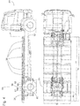
- Figure 2 shows a composite group (53), which comprises several different interconnected lining modules.
- the composite group (53) can be seen once in the side view and once in the top view.
- a cross section through the composite group (53) along a line AB is also shown.
- the composite group (53) is provided for lining the floor of a loading area of a truck, and is therefore also called a floor group. It consists of an elongated lining module (54), the cross section of which essentially corresponds to that of the lining module (1) from the Figure 1a ) corresponds. An end section of the lining module (54) has on one side an extending to the center of the lining module (54) lateral recess (55). In this recess (55) two lining modules (56) and (57), which lie against one another with their side walls and are oriented at right angles to the lining module (54), partially engage.
- a lining module (58) oriented parallel to the lining module (54) bears against the lining module (54) on a side facing away from the recess (55).
- the lining module (58) has a recess (59) in its cover plate, which is provided for a wheel arch of the truck.
- a lining module (60) oriented at right angles to the latter lies against the lining module (54), so that the lining modules (54) and (60) essentially one Form T shape. All lining modules (54), (56), (57), (58) and (60) have the same height, their respective upper sides and their respective lower sides being flush with one another.
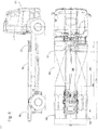
- the side-by-side lining modules (56) and (57) are in the Figure 3 presented in more detail.
- connecting devices (61) can be seen, with which the lining modules (56) and (57) are detachably connected to one another.
- Figure 3c ) shows a cross section through the lining modules (56) and (57) along one in the Figure 3b ) drawn line AB, which runs through one of the connecting devices (61).
- One of the connecting devices (61) is in the Figure 3d ), which is an enlarged section of the side view from the Figure 3a ) acts while the Figure 3e ) again an enlarged section of the Figure 3c ) is.
- a side wall (62) of the lining module (57) facing away from the lining module (56) has an opening (63)
- a side wall (64) of the lining module (57) facing the lining module (56) has an opening (65 )
- a side wall (66) of the lining module (56) facing the lining module (57) has an opening (67)
- a side wall (68) of the lining module (56) facing away from the lining module (57) has an opening (69) on. All openings (63), (65), (67) and (69) are aligned.
- An insert element (70) with a substantially U-shaped cross section is inserted into the side wall (62), said insert element having a bottom (71), a circumferential side wall (72) and an end of the side wall (72) opposite the bottom (71) has circumferential projection (73).
- a continuous bore (74) is provided in the bottom (71).
- the insert element (70) extends through the opening (63), the base (71) protruding into the cavity of the lining module (57) and the projection (73) resting on an outer surface of the side wall (62).
- An insert element (75) corresponding to the insert element (70) extends through the openings (65) and (67).
- insert element (75) In the case of the insert element (75), however, its circumferential projection (76) lies against an inner surface of the side wall (64) and is firmly connected to it, while the bottom (77) thereof partially projects into the cavity of the lining module (56).
- an insert element (78) which corresponds to the insert elements (70) and (75), extends through the opening (69), with its projection abuts an outer surface of the side wall (68) and projects with its bottom into the cavity of the lining module (56).
- a rod (79) extends through the bores of the insert elements (70), (75) and (78) and across the cavities of the lining modules (56) and (57), the end sections of which each have an external thread.
- a respective nut (80) is screwed onto each of these external threads.
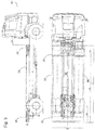
- the lining modules (35) are aligned transversely to a longitudinal axis of the truck and each abut one another with their side faces. With their basic elements, they rest on a frame (82) of the truck (81), which serves as a base for the basic elements.
- a rear wheel axle (83) of the truck (81) there is a lining module (84) with a base element (85) bent in the shape of a segment of a circle and a cover plate (86) as well as two side walls (87) and (88).
- the basic element (85) abuts the cover plate (86) in the center, whereby two cavities (89) and (90) are formed in the lining module (84).
- the cavity (89) is enclosed by part of the base element (85), part of the cover plate (86) and the side wall (87), while the cavity (90) is part of the base element (85), part of the cover plate (86) and the side wall (88) is enclosed.
- the aligned cover plates of all lining modules (35) and (84) form a loading area of the loading area or the loading platform of the truck (81).
- the lining modules (35) and (84) can, for example, be individually mounted on the truck (81), or individual or all of the lining modules (35) and (84) can be connected to one or more composite groups mounted on the truck (81) .
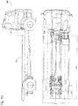
- FIG 6 shows a truck (91), in which a part of its loading area is occupied by a lifting device (92) with left and right lifting platforms in the direction of travel of the truck (91). Between the lifts is a lining module (35) according to the Figure 1a ) arranged. Longitudinal of the truck (91) is the loading area on both sides of the lifting device (92) with lining modules (35) oriented transversely to the longitudinal axis of the truck (91) according to the Figure 1a ) and with a lining module (84) according to the Figure 4 lined.
- the truck (93) shown is a front end section of the loading area with a lining module (35) oriented transversely to the longitudinal axis of the truck (93) according to FIG Figure 1a ) Mistake.
- FIG. 8 In the truck (95) the Figure 8 is the same as in the previous case Figure 7 a front end section of the loading area with a lining module (35) oriented transversely to the longitudinal axis of the truck (95) according to FIG Figure 1a ) Mistake.
- a lifting device (92) closes to the rear of the truck (95) according to FIG Figure 6 to the lining module (35) with a left and a right lifting platform in the direction of travel of the truck (95).
- a lining module (94) which is oriented parallel to the longitudinal axis of the truck (95), extends between the lifting platforms according to FIG Figure 7 from the lining module (35) to the end of the loading area.
- a lining module (96) In the direction of travel of the truck (95) left and right of the lining module (94) there is a lining module (96) oriented on both sides, parallel to the longitudinal axis of the truck (95), with a side surface on the lining module (94) and with an end surface on the lifting device (92 ) on.
- the lining modules (96) have basic elements with an arcuate section which is central in the longitudinal direction and is positioned above the rear axle of the truck (95).
- the truck (97) of the Figure 9 has a lining module (35) oriented transversely to the longitudinal axis of the truck (97) at a front and a rear end section of its loading area in accordance with FIG Figure 1a ) on.
- a lining module (98) arranged next to one another and aligned parallel to the longitudinal axis of the truck (97), the basic elements of which each have an arcuate section in a rear end section, which is positioned above the rear axle of the truck (97).
- the truck (99) is the Figure 10 a loading area with three lining modules (93) arranged next to one another and parallel to the longitudinal axis of the truck (99) according to the Figure 7 lined, each having an arcuate portion which is positioned above the rear axle of the truck (99).
Description
Die vorliegende Erfindung betrifft ein Kraftfahrzeug mit wenigstens einem Auskleidungsmodul, ein Auskleidungsmodul sowie eine Verbundgruppe mit wenigstens zwei Auskleidungsmodulen.The present invention relates to a motor vehicle with at least one lining module, a lining module and a composite group with at least two lining modules.
Aus der
Die
Ferner ist in der
Die
Die
Aus der
Die
Die
Es ist die Aufgabe der vorliegenden Erfindung, ein Kraftfahrzeug mit wenigstens einem Auskleidungsmodul, ein Auskleidungsmodul sowie eine Verbundgruppe mit Auskleidungsmodulen zu schaffen, die sich gegenüber bekannten Kraftfahrzeugen, Auskleidungsmodulen und Verbundgruppen durch eine erhöhte Praktikabilität, Flexibilität und Beständigkeit auszeichnen.It is the object of the present invention to create a motor vehicle with at least one lining module, a lining module and a composite group with lining modules which are distinguished from known motor vehicles, lining modules and composite groups by increased practicability, flexibility and durability.
Diese Aufgabe wird durch das Kraftfahrzeug mit den Merkmalen des Anspruchs 1, durch das Auskleidungsmodul mit den Merkmalen des Anspruchs 9 und durch die Verbundgruppe mit den Merkmalen des Anspruchs 10 gelöst. Bevorzugte Ausführungsformen sind Gegenstand der abhängigen Ansprüche.This object is achieved by the motor vehicle with the features of claim 1, by the lining module with the features of
Ein Kraftfahrzeug gemäß der vorliegenden Erfindung weist wenigstens ein Auskleidungsmodul auf, das wenigstens einen Teil eines Ladebereichs oder wenigstens einen Teil einer Wandfläche des Kraftfahrzeugs abdeckt und das wenigstens ein Grundelement, wenigstens zwei Seitenwände sowie wenigstens eine Deckplatte umfasst, wobei das Grundelement zum wenigstens teilweisen Anlegen des Auskleidungsmoduls an einer Unterlage vorgesehen ist, die Seitenwände wenigstens an zwei entgegengesetzten Endabschnitten des Grundelements mit diesem verbunden sind und die Deckplatte an dem Grundelement abgewandten Randabschnitten der Seitenwände gehalten ist, wobei Grundelement, Seitenwände und Deckplatte wenigstens einen Hohlraum umschließen. Entsprechend umfasst ein erfindungsgemäßes Auskleidungsmodul zum Abdecken wenigstens eines Teils eines Ladebereichs oder einer Wandfläche eines Kraftfahrzeugs wenigstens ein Grundelement das zum wenigstens teilweisen Anlegen des Auskleidungsmoduls an einer Unterlage vorgesehen ist, wenigstens zwei an entgegengesetzten Endabschnitten des Grundelements mit diesem verbundene Seitenwände sowie wenigstens eine Deckplatte, die an dem Grundelement abgewandten Randabschnitten der Seitenwände gehalten ist, wobei Grundelement, Seitenwände und Deckplatte wenigstens einen Hohlraum umschließen. Eine Verbundgruppe gemäß der vorliegenden Erfindung umfasst wenigstens zwei miteinander verbundene derartige Auskleidungsmodule.A motor vehicle according to the present invention has at least one lining module, which at least part of a Covering the loading area or at least a part of a wall surface of the motor vehicle and which comprises at least one base element, at least two side walls and at least one cover plate, the base element being provided for at least partial application of the lining module on a base, the side walls at least on two opposite end sections of the base element are connected to it and the cover plate is held on edge sections of the side walls facing away from the base element, the base element, side walls and cover plate enclosing at least one cavity. Correspondingly, a lining module according to the invention for covering at least a part of a loading area or a wall surface of a motor vehicle comprises at least one base element which is provided for at least partially fitting the lining module on a base, at least two side walls connected to the base element at opposite end sections and at least one cover plate which is held on the edge sections of the side walls facing away from the base element, the base element, side walls and cover plate enclosing at least one cavity. A composite group according to the present invention comprises at least two such lining modules connected to one another.
Im Unterschied zu bekannten Kraftfahrzeugen, Auskleidungsmodulen und Verbundgruppen wird gemäß der vorliegenden Erfindung beim Auskleidungsmodul auf Tragwerke wie T-, Doppel-T-Träger, Traversen, Stegbleche beziehungsweise Wabenelemente verzichtet. Stattdessen weist das Auskleidungsmodul einen Hohlraum auf, der sich auf vielfältige Weise nutzen lässt. So können in demselben Leitungen, Aggregate und Steuergeräte wie in einem Installationskanal in von außen geschützter Position untergebracht werden, was bei bekannten Auskleidungsmodulen aufgrund der diversen Tragwerke nicht möglich ist. Im Innenraum des Auskleidungsmoduls ist dagegen eine saubere und geschützte Leitungsführung möglich. Darüber hinaus sind das Kraftfahrzeug, das Auskleidungsmodul und die Verbundgruppe gemäß der vorliegenden Erfindung gegenüber bekannten Kraftfahrzeugen, Auskleidungsmodulen und Verbundgruppen beständiger, da bei letzteren infolge der Tragwerke mannigfache Winkel, Ecken, Kanten und kleinere Räume auftreten, die sich als ausgesprochen korrosionsanfällig erweisen. Gemäß der vorliegenden Erfindung lassen sich Auskleidungsmodule ganz allgemein sowohl zum Aus- oder Verkleiden beziehungsweise Abdecken von Böden oder Lagerbereichen als auch zum Abdecken von insbesondere senkrechten Wänden verwenden. Bei der Unterlage kann es sich zum Beispiel je nach Einsatz des Auskleidungsmoduls entsprechend um eine Bodenfläche oder um einen Rahmen und insbesondere einen Fahrzeugrahmen, oder um eine Wandfläche oder einen oder mehrere Träger handeln. Sofern das Auskleidungsmodul zum Auskleiden eines Lagerbereichs vorgesehen und das Grundelement nach unten hin abgeschlossen ist, bzw. sofern das Grundelement wannenartig vertieft ist und/oder der Hohlraum an von dem Grundelement, den Seitenwänden und der Deckplatte nicht umschlossenen Seiten wenigstens teilweise geschlossen ist, können im Falle des Transports problematischer Transportgüter unbeabsichtigt freigesetzte Flüssigkeiten, Stäube oder andere Schüttgüter in dem Hohlraum aufgefangen werden, wodurch ein Eindringen derselben in das Erdreich verhindert wird. Um im Falle einer Verwendung des Auskleidungsmoduls zum Auskleiden einer Boden- oder Lagerfläche eine mechanische Stabilität desselben zu gewährleisten, sind die Abmessungen des Auskleidungsmoduls zwar abhängig von den zu seiner Herstellung verwendeten Materialien begrenzt, es können zum Auskleiden größerer Flächen jedoch mehrere der Auskleidungsmodule in beliebiger Orientierung zueinander nebeneinander positioniert werden. Folglich kann ein erfindungsgemäßes Kraftfahrzeug mehrere der Auskleidungsmodule mit Flächen, die im Vergleich zur Fläche des auszukleidenden Bereiches klein sind, aufweisen, anstatt wie bei bekannten Kraftfahrzeugen für Bodenflächen wenige großflächige Auskleidungsmodule oder gar nur ein Auskleidungsmodul mit Tragwerken vorzusehen. Dabei können die Auskleidungsmodule in den unterschiedlichsten Bauhöhen und Größen sowie aus unterschiedlichsten Materialien und mit unterschiedlichsten Festigkeiten sowohl maschinell als auch manuell hergestellt werden. Ferner können das Grundelement und/oder die Seitenwände ganz allgemein beliebig geformt sein. So kann wenigstens eine der Seitenwände beliebig gebogen sein. Bevorzugt sind die Seitenwände aber im Wesentlichen eben bzw. plattenartig ausgeführt.In contrast to known motor vehicles, lining modules and composite groups, in accordance with the present invention, in the case of the lining module, structures such as T-, double-T-beams, cross members, web plates or honeycomb elements are dispensed with. Instead, the lining module has a cavity that can be used in a variety of ways. So in the same line, Units and control units can be accommodated in an installation channel in a position protected from the outside, which is not possible with known lining modules due to the various supporting structures. In the interior of the lining module, however, a clean and protected cable routing is possible. In addition, the motor vehicle, the lining module and the composite group according to the present invention are more resistant to known motor vehicles, lining modules and composite groups, since the latter give rise to manifold angles, corners, edges and smaller spaces as a result of the supporting structures, which have proven to be extremely susceptible to corrosion. According to the present invention, lining modules can be used very generally both for lining or covering or covering floors or storage areas and also for covering, in particular, vertical walls. Depending on the use of the lining module, the underlay can be, for example, a floor surface or a frame and in particular a vehicle frame, or a wall surface or one or more supports. If the lining module is intended for lining a storage area and the base element is closed at the bottom, or if the base element is recessed like a trough and / or the cavity on sides not enclosed by the base element, the side walls and the cover plate is at least partially closed, in In the event of the transport of problematic transport goods, unintentionally released liquids, dusts or other bulk goods are caught in the cavity, thereby preventing them from penetrating into the ground. In order to line a floor or storage area in the case of using the lining module To ensure the mechanical stability of the same, the dimensions of the lining module are limited depending on the materials used for its manufacture, but it is possible to position several of the lining modules next to one another in any orientation for lining larger areas. Consequently, a motor vehicle according to the invention can have a plurality of the lining modules with areas which are small in comparison to the area of the area to be lined, instead of providing a few large-area lining modules or even just one lining module with supporting structures for floor areas, as in known vehicles. The lining modules can be manufactured in a wide variety of heights and sizes, as well as from a wide variety of materials and with a wide range of strengths, both mechanically and manually. Furthermore, the base element and / or the side walls can be shaped in any way in general. At least one of the side walls can be bent as desired. However, the side walls are preferably essentially flat or plate-like.
Erfindungsgemäß sind das Grundelement und die Seitenwände als einstückiges Formprofil ausgebildet. Ein derartiges Formprofil zeichnet sich durch eine einfache und billige Herstellungsweise sowie durch eine besonders hohe Stabilität aus.According to the invention, the base element and the side walls are designed as a one-piece shaped profile. Such a shaped profile is characterized by a simple and inexpensive method of manufacture and by a particularly high stability.
Grundsätzlich kann bei dem Auskleidungsmodul die Deckplatte an den Seitenwänden lösbar oder unlösbar gehalten sein. Beispielsweise kann die Deckplatte mit den Randabschnitten der Seitenwände verklebt, vernietet, vernagelt oder verschweißt sein. Eine lösbare Halterung kann mittels Verschraubungen, Verzapfungen, Klammern oder Rasteinrichtungen ausgeführt sein. Dabei können die Randabschnitte der Seitenwände abgewinkelt ausgeführt sein und als An- bzw. Auflagefläche für die Deckplatte dienen. Andererseits können die Randabschnitte nutartige Vertiefungen aufweisen, in welche die Deckplatte mit jeweiligen Randabschnitten einschiebbar ist, oder aber es können schienenartige Vorsprünge an den Randabschnitten der Seitenwände ausgebildet sein, auf die eine mit entsprechenden nutartigen Vertiefungen versehene Deckplatte aufschiebbar ist. Lösbar gehaltene Deckplatten lassen sich vorteilhafterweise schnell und bequem austauschen, ohne dazu das komplette Auskleidungsmodul austauschen zu müssen. So kann beispielsweise bei einem zur Auskleidung eines Lagerbereichs eingesetzten Auskleidungsmodul die Deckplatte auf einfache Weise durch eine lebensmittelechte Deckplatte ausgetauscht werden, sofern der Lagerbereich auf das Lagern von Lebensmitteln umgestellt werden soll. Auf diese Weise lässt sich das Auskleidungsmodul auf vielfältigste Anforderungen, die an die Beschaffenheit der mit Lagergut in Berührung kommenden Materialien gestellt werden, problemlos anpassen.In principle, in the lining module, the cover plate can be held detachably or non-detachably on the side walls. For example, the cover plate can be glued, riveted, nailed or welded to the edge sections of the side walls. A detachable bracket can be screwed, mortised, Brackets or locking devices can be executed. The edge sections of the side walls can be angled and serve as a contact or support surface for the cover plate. On the other hand, the edge sections can have groove-like depressions into which the cover plate can be inserted with respective edge sections, or rail-like projections can be formed on the edge sections of the side walls, onto which a cover plate provided with corresponding groove-like depressions can be pushed. Removable cover plates can advantageously be exchanged quickly and easily without having to replace the entire lining module. For example, in the case of a lining module used for lining a storage area, the cover plate can easily be replaced by a food-safe cover plate if the storage area is to be converted to storing food. In this way, the lining module can be easily adapted to a wide variety of requirements that are placed on the properties of the materials that come into contact with the stored goods.
Die Deckplatte kann je nach den Anforderungen beliebig beschaffen sein. Bevorzugt ist oder umfasst die Deckplatte wenigstens eine Holzplatte und/oder wenigstens eine Siebdruckplatte und/oder wenigstens eine Metallplatte und/oder wenigstens eine Edelstahlplatte und/oder wenigstens eine Aluminiumplatte und/oder wenigstens eine Riffelplatte und/oder wenigstens ein Tränenblech. Ferner kann die Deckplatte wenigstens eine Ausnehmung aufweisen.The cover plate can be of any type depending on the requirements. The cover plate is preferably or comprises at least one wooden plate and / or at least one screen printing plate and / or at least one metal plate and / or at least one stainless steel plate and / or at least one aluminum plate and / or at least one corrugated plate and / or at least one tear plate. Furthermore, the cover plate can have at least one recess.
Besonders bevorzugt weist das Auskleidungsmodul wenigstens eine Verbindungseinrichtung zum lösbaren oder unlösbaren Verbinden des Auskleidungsmoduls mit einem benachbarten Auskleidungsmodul oder einem benachbarten Teil eines Auskleidungsmoduls auf. Dabei können das Grundelement und/oder die Deckplatte und/oder wenigstens eine der Seitenwände die Verbindungseinrichtung wenigstens teilweise oder ganz umfassen. Mit entsprechenden Verbindungseinrichtungen lassen sich benachbarte Auskleidungsmodule oder Teile von Auskleidungsmodulen miteinander verkleben, vernieten, verschweißen, verschrauben, vernageln, verklammern, verzapfen oder verrasten, um die Auskleidungsmodule beispielsweise vor einem gegenseitigen Verschieben zu sichern. Auch können Auskleidungsmodule per Stoß, geklinkert oder durch Überlappung, auch durch Stürzen, zu Einheiten oder Verbundgruppen zusammengefügt werden. Insbesondere lassen sich die Auskleidungsmodule stapelbar ausbilden, indem Unterseiten und Oberseiten einzelner Auskleidungsmodule ineinander einpassbar ausgeformt werden. Derartige Auskleidungsmodule können zum Beispiel zum Höhenausgleich übereinander gestapelt werden, was insbesondere bei Kraftfahrzeugen mit Sattelauflegern vorteilhaft ist. Ferner lassen sich durch Übereinanderstapeln der Auskleidungsmodule mehrere Ebenen derselben ausbilden, bzw. bei entsprechender Anordnung von Auskleidungsmodulen mit durchgängigen und beidseitig offenen Hohlräumen mehrere Ebenen von Schächten.The lining module particularly preferably has at least one connecting device for releasably or non-releasably connecting the lining module to an adjacent lining module or an adjacent part of a lining module. The base element and / or the cover plate and / or at least one of the side walls can at least partially or entirely include the connecting device. With appropriate connecting devices, adjacent lining modules or parts of lining modules can be glued, riveted, welded, screwed, nailed, clamped, mortised or latched together in order to secure the lining modules against mutual displacement, for example. Lining modules can also be joined to form units or composite groups by pushing, clinking or by overlapping, also by falling. In particular, the lining modules can be designed to be stackable, in that the undersides and tops of individual lining modules are shaped so that they can fit into one another. Lining modules of this type can, for example, be stacked one above the other for height compensation, which is particularly advantageous in motor vehicles with semitrailers. Furthermore, by stacking the lining modules on top of each other, several levels of the same can be formed, or, with a corresponding arrangement of lining modules with continuous cavities that are open on both sides, several levels of shafts.
Bei einem Auskleidungsmodul können die Seitenwände in einer Längsrichtung des Auskleidungsmoduls unterschiedlich oder gleich lang sein. Unterschiedlich lange Seitenwände sind zum Beispiel dann bevorzugt, wenn zwei zueinander rechtwinklig orientierte Auskleidungsmodule aneinandergefügt werden, von denen eines unterschiedlich lange Seitenwände umfasst und das jeweils andere Auskleidungsmodul in eine von der kürzeren Seitenwand freigegebene Ausnehmung des ersten Auskleidungsmoduls eingreift.In a lining module, the side walls in a longitudinal direction of the lining module can be different or the same length. Sidewalls of different lengths are preferred, for example, if two are oriented at right angles to one another Lining modules are joined together, one of which comprises side walls of different lengths and the other lining module engages in a recess of the first lining module which is released by the shorter side wall.
Eine Ausführungsform der vorliegenden Erfindung weist ein Auskleidungsmodul auf, das ein Isoliermaterial umfasst oder mit einem Isoliermaterial ausgekleidet ist. Derartige Auskleidungsmodule werden bevorzugt zum Auskleiden wenigstens eines Teils einer Wand eingesetzt.An embodiment of the present invention has a lining module that comprises an insulating material or is lined with an insulating material. Such lining modules are preferably used to line at least part of a wall.
Ganz allgemein kann sich der Hohlraum in einer Längsrichtung des Auskleidungsmoduls frei durchgängig erstrecken und beidseitig offen sein und/oder es kann wenigstens ein Funktionselement im Hohlraum angeordnet sein. Das Funktionselement kann beliebig sein. Beispielsweise kann es sich bei dem Funktionselement um eine Halte- oder Klemmeinrichtung zum Fixieren von durch den Hohlraum geführten Kabeln oder Kabelbäumen handeln, oder um eine Quer- oder Stirnwand, die beliebig viele Öffnungen aufweisen kann. Im Falle größerer Belastungen des Auskleidungsmoduls kann es sich bei dem Funktionselement auch um ein zur mechanischen Verstärkung des Auskleidungsmoduls an einer entsprechenden Stelle vorgesehenes, beispielsweise in das Auskleidungsmodul eingeschweißtes, Stegblech handeln.In very general terms, the cavity can extend freely continuously in a longitudinal direction of the lining module and be open on both sides and / or at least one functional element can be arranged in the cavity. The functional element can be any. For example, the functional element can be a holding or clamping device for fixing cables or cable harnesses guided through the cavity, or a transverse or end wall which can have any number of openings. In the event of greater loads on the lining module, the functional element can also be a web plate provided for mechanical reinforcement of the lining module at a corresponding point, for example welded into the lining module.
Die Seitenwände des Auskleidungsmoduls können zueinander parallel ausgerichtet sein oder sie können einen Winkel bilden. So kann wenigstens eine der Seitenwände mit dem Grundelement und/oder mit der Deckplatte einen rechten Winkel oder einen Winkel bilden, der kleiner oder größer ist als 90°. Derartig ausgeführte Auskleidungsmodule können beispielsweise zur besseren Raumnutzung in Ausnehmungen von Begrenzungselementen eines auszukleidenden Bereiches eingreifen. Ferner können die Seitenwände in einer Längsrichtung des Auskleidungsmoduls keilförmig aufeinander zulaufen, um auch Flächen mit sich ändernden Abmessungen mit Auskleidungsmodulen möglichst vollständig auszukleiden.The side walls of the lining module can be aligned parallel to one another or they can form an angle. At least one of the side walls can make a right angle or an angle with the base element and / or with the cover plate form that is smaller or larger than 90 °. Lining modules designed in this way can intervene, for example, for better use of space in recesses of boundary elements of an area to be lined. Furthermore, the side walls can run in a wedge shape towards one another in a longitudinal direction of the lining module in order also to line surfaces with changing dimensions as completely as possible with lining modules.
Bevorzugte Ausführungsformen der Erfindung werden nachfolgend anhand von Figuren näher erläutert. Es zeigen:
- Figur 1a)
- Querschnitte durch mehrere unterschiedliche Auskleidungsmodule;
- Figur 1b)
- eine Draufsicht auf ein Auskleidungsmodul;
Figur 2- eine Verbundgruppe;
- Figur 3
- zwei miteinander verbundene Auskleidungsmodule;
Figur 4- einen Lastkraftwagen, dessen Ladebereich mit Auskleidungsmodulen ausgekleidet ist;
Figur 5- einen weiteren Lastkraftwagen, dessen Ladebereich mit Auskleidungsmodulen ausgekleidet ist;
Figur 6- einen weiteren Lastkraftwagen, dessen Ladebereich mit Auskleidungsmodulen ausgekleidet ist;
Figur 7- einen weiteren Lastkraftwagen, dessen Ladebereich mit Auskleidungsmodulen ausgekleidet ist;
Figur 8- einen weiteren Lastkraftwagen, dessen Ladebereich mit Auskleidungsmodulen ausgekleidet ist;
Figur 9- einen weiteren Lastkraftwagen, dessen Ladebereich mit Auskleidungsmodulen ausgekleidet ist; und
Figur 10- einen weiteren Lastkraftwagen, dessen Ladebereich mit Auskleidungsmodulen ausgekleidet ist.
- Figure 1a)
- Cross sections through several different lining modules;
- Figure 1b)
- a plan view of a lining module;
- Figure 2
- a composite group;
- Figure 3
- two interconnected lining modules;
- Figure 4
- a truck, the loading area of which is lined with lining modules;
- Figure 5
- another truck, the loading area is lined with lining modules;
- Figure 6
- another truck, the loading area is lined with lining modules;
- Figure 7
- another truck, the loading area is lined with lining modules;
- Figure 8
- another truck, the loading area is lined with lining modules;
- Figure 9
- another truck, the loading area is lined with lining modules; and
- Figure 10
- another truck, the loading area is lined with lining modules.
In der
Ein in der
Eine Draufsicht auf das Auskleidungsmodul (1) ist in der
Beim Auskleidungsmodul (1) ist die Deckplatte (5) mit den Vorsprüngen (11) und (12) lediglich in die von den Randabschnitten (6) und (7) und von den L-Profilen (8) und (9) gebildeten Nuten eingeschoben und nicht mit dem Unterbau (10) des Auskleidungsmoduls (1) verbunden. Jedoch ist es auch möglich, die Deckplatte (5) mit dem Unterbau (10) bzw. mit den Seitenwänden (3) und (4) lösbar oder unlösbar zu verbinden. Beispielsweise können in gleichmäßigen Abständen im Randabschnitt (6), im L-Profil (8) und im Vorsprung (11) jeweils miteinander fluchtende Öffnungen vorgesehen sein, durch die Schrauben steckbar sind, um eine Schraubverbindung zwischen Deckplatte (5) und Seitenwand (3) zu ermöglichen. Entsprechende Öffnungen können im Randabschnitt (7), im Vorsprung (9) und im L-Profil (12) vorgesehen sein. Damit lässt sich die Deckplatte (5) einerseits mit dem Unterbau (10) verbinden. Andererseits kann die Deckplatte (5) einfach und schnell durch lösen der Schraubverbindung vom Unterbau (10) getrennt und entfernt oder ausgetauscht werden.In the lining module (1), the cover plate (5) with the projections (11) and (12) is only inserted into the grooves formed by the edge sections (6) and (7) and by the L-profiles (8) and (9) and not connected to the substructure (10) of the lining module (1). However, it is also possible to connect the cover plate (5) to the substructure (10) or to the side walls (3) and (4) in a detachable or non-detachable manner. For example, openings that are aligned with one another can be provided at regular intervals in the edge section (6), in the L-profile (8) and in the projection (11), through which screws can be inserted in order to achieve a screw connection between the cover plate (5) and the side wall (3). to enable. Corresponding openings can be provided in the edge section (7), in the projection (9) and in the L-profile (12). The cover plate (5) can thus be connected to the substructure (10) on the one hand. On the other hand, the cover plate (5) can be separated and removed or replaced simply and quickly by loosening the screw connection from the substructure (10).
Der Hohlraum (13) wird erfindungsgemäß zur Aufnahme einer oder mehrerer Querwände (14) in den Hohlraum (13) verwendet. Entsprechend ist in der
Vom Auskleidungsmodul (1) sind verschiedene Abwandlungen möglich.Various modifications of the lining module (1) are possible.
So ist beim ebenfalls in der
Bei einem anderen aus gebogenem Blech hergestellten Auskleidungsmodul (24) sind jeweilige Randabschnitte (25) und (26) der Seitenwände (27) und (28) derart gebogen, dass sie Auflageflächen (29) und (30) mit jeweiligen seitlichen Anschlägen (32) und (33) für eine Deckplatte (31) bilden. Bei der Deckplatte (31) handelt es sich um eine einfache Platte ohne Vorsprünge, die mit entgegengesetzten Randabschnitten jeweils auf den Auflageflächen (29) und (30) aufliegt und mit entgegengesetzten Seiten jeweils an den Anschlägen (32) und (33) anschlägt. Auch das Auskleidungsmodul (24) ist einmal ohne und einmal mit einer Querwand (34) zu sehen.In another lining module (24) made from bent sheet metal, respective edge sections (25) and (26) of the side walls (27) and (28) are bent in such a way that they support surfaces (29) and (30) with respective lateral stops (32). and (33) form for a cover plate (31). The cover plate (31) is a simple plate without projections, which rests with opposite edge sections on the support surfaces (29) and (30) and strikes the stops (32) and (33) with opposite sides. The lining module (24) can also be seen once without and once with a transverse wall (34).
Eine Abwandlung des Auskleidungsmoduls (24) stellt das Auskleidungsmodul (35) dar, bei dem Z-Profile (36) und (37) derart auf abgewinkelten Randabschnitten (38) und (39) der Seitenwände (40) und (41) angeschweißt sind, dass ähnlich dem Auskleidungsmodul (24) Auflagen für eine plattenförmige Deckplatte (42) vorliegen. Wie bei den vorherigen Beispielen ist auch das Auskleidungsmodul (35) einmal ohne und einmal mit einer Querwand (43) dargestellt.A modification of the lining module (24) is the lining module (35), in which the Z-profiles (36) and (37) are welded to angled edge sections (38) and (39) of the side walls (40) and (41), similar to the lining module (24), there are supports for a plate-shaped cover plate (42). As in the previous examples, the lining module (35) is shown once without and once with a transverse wall (43).
Schließlich zeigt die
Wie bei dem Auskleidungsmodul (1) können auch bei allen anderen der gezeigten Auskleidungsmodule die jeweiligen Deckplatten mit den jeweiligen Unterbauten lösbar oder unlösbar verbunden sein.As with the lining module (1), the respective cover plates can also be releasably or non-releasably connected to the respective substructures in all the other lining modules shown.
Die Verbundgruppe (53) ist zum Auskleiden des Bodens eines Ladebereichs eines Lastwagens vorgesehen, und wird daher auch Bodengruppe genannt. Sie besteht aus einem länglichen Auskleidungsmodul (54), dessen Querschnitt im Wesentlichen demjenigen des Auskleidungsmoduls (1) aus der
Die seitlich aneinander liegenden Auskleidungsmodule (56) und (57) sind in der
Wie insbesondere in den
Einen Lastkraftwagen (81) mit einem Ladebereich, der unter anderem mit mehreren Auskleidungsmodulen (35) gemäß der
An der zur Rückseite des Lastkraftwagens (81) zugewandten Seite des Auskleidungsmoduls (84) ist in der
Beim in der
Beim Lastkraftwagen (95) der
Der Lastkraftwagen (97) der
Schließlich ist beim Lastkraftwagen (99) der
Claims (10)
- A motor vehicle (81, 91, 93, 95, 97, 99) having at least one lining module (1, 16, 24, 35, 44, 54, 56, 57, 58, 60, 84, 94, 96, 98) which covers at least one part of a loading area or at least one part of a wall surface of the motor vehicle (81, 91, 93, 95, 97, 99) and comprises at least one base element (2, 49, 85), at least two side walls (3, 4, 27, 28, 40, 41, 47, 48, 62, 64, 66, 68, 87, 88) and at least one ceiling panel (5, 20, 31, 42, 50, 86), the base element (2, 49, 85) being provided for the at least partial arrangement of the lining module (1, 16, 24, 35, 44, 54, 56, 57, 58, 60, 84, 94, 96, 98) on a support (82), the side walls (3, 4, 27, 28, 40, 41, 47, 48, 62, 64, 66, 68, 87, 88) being connected to the base element (2, 49, 85) at least at two opposite end sections of said base element (2, 49, 85), and the ceiling panel (5, 20, 31, 42, 50, 86) being held on edge sections (6, 7, 25, 26, 38, 39, 45, 46) of the side walls (3, 4, 27, 28, 40, 41, 47, 48, 62, 64, 66, 68, 87, 88), which edge sections (6, 7, 25, 26, 38, 39, 45, 46) face away from the base element (2, 49, 85), the base element (2, 49, 85), side walls (3, 4, 27, 28, 40, 41, 47, 48, 62, 64, 66, 68, 87, 88) and ceiling panel (5, 20, 31, 42, 50, 86) enclosing at least one hollow space (13, 17, 89, 90), characterized in that at least one transverse wall (14, 18, 34, 43) is placed in the hollow space (13, 17, 89, 90), and that the base element (2, 49, 85) and the side walls (3, 4, 27, 28, 40, 41, 47, 48, 62, 64, 66, 68, 87, 88) are configured as a single-piece shaped profile.
- The motor vehicle (81, 91, 93, 95, 97, 99) as claimed in claim 1, the ceiling panel (5, 20, 31, 42, 50, 86) being held releasably or non-releasably on the side walls (3, 4, 27, 28, 40, 41, 47, 48, 62, 64, 66, 68, 87, 88).
- The motor vehicle (81, 91, 93, 95, 97, 99) as claimed in one of the preceding claims, the ceiling panel (5, 20, 31, 42, 50, 86) being or comprising at least one wood panel and/or at least one film coated plywood panel and/or at least one metal panel and/or at least one stainless steel panel and/or at least one aluminum panel and/or at least one corrugated panel and/or at least one diamond plate, and/or the ceiling panel (5, 20, 31, 42, 50, 86) having at least one recess (59).
- The motor vehicle (81, 91, 93, 95, 97, 99) as claimed in one of the preceding claims, the lining module (56, 57) having at least one connecting device (61) for the releasable or non-releasable connection of the lining module (56, 57) to an adjacent lining module (56, 57) or an adjacent part of a lining module (56, 57).
- The motor vehicle (81, 91, 93, 95, 97, 99) as claimed in one of the preceding claims, the side walls being different or equally long in a longitudinal direction of the lining module (54).
- The motor vehicle (81, 91, 93, 95, 97, 99) as claimed in one of the preceding claims, the lining module (1, 16, 24, 35, 44, 54, 56, 57, 58, 60, 84, 94, 96, 98) comprising an insulating material or being lined with an insulating material.
- The motor vehicle (81, 91, 93, 95, 97, 99) as claimed in one of the preceding claims, the hollow space (13, 17, 89, 90) of the lining module (1, 16, 24, 35, 44, 54, 56, 57, 58, 60, 84, 94, 96, 98) extending in a freely continuous manner in a longitudinal direction of the lining module (1, 16, 24, 35, 44, 54, 56, 57, 58, 60, 84, 94, 96, 98) and being open on both sides.
- The motor vehicle (81, 91, 93, 95, 97, 99) as claimed in one of the preceding claims, in which the side walls (3, 4, 27, 28, 40, 41, 47, 48, 62, 64, 66, 68, 87, 88) of the lining module (1, 16, 24, 35, 44, 54, 56, 57, 58, 60, 84, 94, 96, 98) are oriented parallel to one another, or in which the side walls form an angle.
- A lining module (1, 16, 24, 35, 44, 54, 56, 57, 58, 60, 84, 94, 96, 98) for covering at least one part of a loading area or a wall surface of a motor vehicle (81, 91, 93, 95, 97, 99) as claimed in one of claims 1 to 8, which lining module (1, 16, 24, 35, 44, 54, 56, 57, 58, 60, 84, 94, 96, 98) comprises at least one base element (2, 49, 85) which is provided for the at least partial arrangement of the lining module (1, 16, 24, 35, 44, 54, 56, 57, 58, 60, 84, 94, 96, 98) on a support (82), at least two side walls (3, 4, 27, 28, 40, 41, 47, 48, 62, 64, 66, 68, 87, 88) which are connected to the base element (2, 49, 85) at opposite end sections of said base element (2, 49, 85) and at least one ceiling panel (5, 20, 31, 42, 50, 86) which is held on edge sections (6, 7, 25, 26, 38, 39, 45, 46) of the side walls (3, 4, 27, 28, 40, 41, 47, 48, 62, 64, 66, 68, 87, 88), which edge sections (6, 7, 25, 26, 38, 39, 45, 46) face away from the base element (2, 49, 85), the base element (2, 49, 85), side walls (3, 4, 27, 28, 40, 41, 47, 48, 62, 64, 66, 68, 87, 88) and ceiling panel (5, 20, 31, 42, 50, 86) enclosing at least one hollow space (13, 17, 89, 90).
- A composite group (53) having at least two lining modules (3, 4, 27, 28, 40, 41, 47, 48, 62, 64, 66, 68, 87, 88) as claimed in claim 9 which are connected to one another.
Applications Claiming Priority (2)
| Application Number | Priority Date | Filing Date | Title |
|---|---|---|---|
| DE102010001540A DE102010001540A1 (en) | 2010-02-03 | 2010-02-03 | Motor vehicle with lining module, lining module and composite group |
| PCT/EP2011/051569 WO2011095548A1 (en) | 2010-02-03 | 2011-02-03 | Motor vehicle having a lining module, lining module and composite group |
Publications (2)
| Publication Number | Publication Date |
|---|---|
| EP2526007A1 EP2526007A1 (en) | 2012-11-28 |
| EP2526007B1 true EP2526007B1 (en) | 2020-07-29 |
Family
ID=42733611
Family Applications (1)
| Application Number | Title | Priority Date | Filing Date |
|---|---|---|---|
| EP11709024.1A Active EP2526007B1 (en) | 2010-02-03 | 2011-02-03 | Vehicle with covering module, covering module and assembly set |
Country Status (8)
| Country | Link |
|---|---|
| US (1) | US20120299325A1 (en) |
| EP (1) | EP2526007B1 (en) |
| JP (1) | JP2013518762A (en) |
| KR (1) | KR20120139714A (en) |
| CN (1) | CN102858623A (en) |
| DE (2) | DE102010001540A1 (en) |
| ES (1) | ES2817881T3 (en) |
| WO (1) | WO2011095548A1 (en) |
Families Citing this family (1)
| Publication number | Priority date | Publication date | Assignee | Title |
|---|---|---|---|---|
| FR2970232A1 (en) * | 2011-01-11 | 2012-07-13 | Philippe Remy Marcel Collemiche | Modular base for e.g. commercial vehicle, has universal clamping rail including support for providing calculated deformation of rail to prohibit all longitudinal and lateral movement to body of vehicle |
Family Cites Families (19)
| Publication number | Priority date | Publication date | Assignee | Title |
|---|---|---|---|---|
| GB771298A (en) * | 1955-09-13 | 1957-03-27 | Peter Leonard Gossling | Improvements relating to the construction of vehicle body floors |
| US3177533A (en) * | 1962-05-21 | 1965-04-13 | Lawrence E Davis | Door construction |
| US3681883A (en) * | 1970-09-28 | 1972-08-08 | Donald J Ehrlich | Trailer and channeled floor assembly therewith |
| US4267679A (en) * | 1976-12-27 | 1981-05-19 | Steelite, Inc. | Insulated building panel wall construction |
| GB8407119D0 (en) * | 1984-03-19 | 1984-04-26 | British Alcan Aluminium Ltd | Vehicle body construction |
| SE457163B (en) * | 1987-05-19 | 1988-12-05 | Sture Simme | POOL FOR LASTFORDON |
| DE3906628C3 (en) | 1989-03-02 | 1994-12-22 | Peter Schmitz | Floor platform for a chassis of semi-trailers |
| DE4016209A1 (en) * | 1990-05-19 | 1991-11-21 | Iveco Magirus | BOX CONSTRUCTION, ESPECIALLY FOR COMMERCIAL VEHICLES LIKE FIRE PROTECTION VEHICLES |
| US5597193A (en) * | 1994-05-31 | 1997-01-28 | Conner; Robert H. | Interlocking panel truck bed liners |
| JPH09249158A (en) * | 1996-03-14 | 1997-09-22 | Nippon Light Metal Co Ltd | Gate for truck |
| US5791714A (en) * | 1996-08-16 | 1998-08-11 | Sundowner Trailers, Inc. | Floor system for towable horse trailers |
| JPH11250632A (en) * | 1998-03-02 | 1999-09-17 | Pioneer Electron Corp | Information recording medium and information recording medium reproducing apparatus |
| GB9810968D0 (en) * | 1998-05-22 | 1998-07-22 | Bonnington Plastics Limited | Decking plank |
| US6729671B2 (en) * | 1999-12-23 | 2004-05-04 | Annette Lily Keles | Device for the conversion of the interior space of a vehicle |
| EP1445178B1 (en) | 2003-02-06 | 2009-04-15 | Aghito Sistemi S.r.l. | Floor of a vehicle for load carrying |
| US7726720B2 (en) * | 2003-09-17 | 2010-06-01 | Roll-Rite, Llc | Trailer cover system |
| US7178860B2 (en) * | 2005-04-22 | 2007-02-20 | Vantage Trailers, Inc. | Trailer having reduced weight wall construction |
| DE102007020589B4 (en) | 2007-05-02 | 2013-02-28 | Kögel Trailer GmbH & Co. KG | Utility vehicle, ground for a utility vehicle, method of manufacturing a utility vehicle |
| CN101214666B (en) * | 2008-01-14 | 2012-07-04 | 南京林业大学 | Skid-proof container floor and manufacturing method thereof |
-
2010
- 2010-02-03 DE DE102010001540A patent/DE102010001540A1/en not_active Withdrawn
- 2010-06-02 DE DE202010007523U patent/DE202010007523U1/en not_active Expired - Lifetime
-
2011
- 2011-02-03 KR KR1020127022606A patent/KR20120139714A/en not_active Application Discontinuation
- 2011-02-03 EP EP11709024.1A patent/EP2526007B1/en active Active
- 2011-02-03 US US13/576,862 patent/US20120299325A1/en not_active Abandoned
- 2011-02-03 CN CN2011800171692A patent/CN102858623A/en active Pending
- 2011-02-03 JP JP2012551621A patent/JP2013518762A/en active Pending
- 2011-02-03 WO PCT/EP2011/051569 patent/WO2011095548A1/en active Application Filing
- 2011-02-03 ES ES11709024T patent/ES2817881T3/en active Active
Non-Patent Citations (1)
| Title |
|---|
| None * |
Also Published As
| Publication number | Publication date |
|---|---|
| ES2817881T3 (en) | 2021-04-08 |
| DE102010001540A1 (en) | 2011-08-04 |
| WO2011095548A1 (en) | 2011-08-11 |
| EP2526007A1 (en) | 2012-11-28 |
| CN102858623A (en) | 2013-01-02 |
| JP2013518762A (en) | 2013-05-23 |
| DE202010007523U1 (en) | 2010-09-09 |
| KR20120139714A (en) | 2012-12-27 |
| US20120299325A1 (en) | 2012-11-29 |
Similar Documents
| Publication | Publication Date | Title |
|---|---|---|
| EP0063214B1 (en) | Assembly of a vehicle floor sub-assembly with fixing means | |
| DE102012212305B4 (en) | Loading floor and method for producing a loading floor | |
| DE202011051401U1 (en) | load floor | |
| DE202009007881U1 (en) | Transport pallet for transporting goods, in particular solar panels or solar modules | |
| CH707201A2 (en) | Fixing element for positioning cuboid container in a vertical stack. | |
| DE102007020589B4 (en) | Utility vehicle, ground for a utility vehicle, method of manufacturing a utility vehicle | |
| DE102010055198A1 (en) | Device for mounting a passenger restraint system with a safety belt arrangement and floor panel of a vehicle | |
| EP2722285B1 (en) | Plastic pallet with stiffening element | |
| EP2526007B1 (en) | Vehicle with covering module, covering module and assembly set | |
| DE102012100801A1 (en) | Stackable pallet container | |
| EP3090926B1 (en) | Floor of a structure of a commercial vehicle | |
| DE4335478C2 (en) | Locking bar fuse | |
| EP0685380A1 (en) | Guiding profile for loading floor of transport vehicles | |
| EP3578439A1 (en) | Lightweight chassis | |
| EP2524855B1 (en) | Structure for a commercial vehicle | |
| EP3388317B1 (en) | Refrigeration vehicle structure | |
| DE102010000115A1 (en) | Loading area for e.g. lorry, has two front strips attached at two opposite edges of base plate such that curvature of base plate is reduced during loading process, where front ends of base plate are supported at front strips of frame | |
| EP2103502A1 (en) | Commercial vehicle with a box body | |
| DE102005022006B4 (en) | Stiffening arrangement for a motor vehicle body | |
| DE202007001329U1 (en) | Load securing lath system for a vehicle, trailer or trailer wall | |
| DE19746696C2 (en) | Profile plate for loading goods | |
| EP2505460A2 (en) | Loading floor with high sliding friction coefficient | |
| EP3590798B1 (en) | Box body of a commercial vehicle with parallel portals | |
| DE202008009246U1 (en) | Transport pallet for the transport of goods | |
| DE102010045430B4 (en) | Swap body for a commercial vehicle |
Legal Events
| Date | Code | Title | Description |
|---|---|---|---|
| PUAI | Public reference made under article 153(3) epc to a published international application that has entered the european phase |
Free format text: ORIGINAL CODE: 0009012 |
|
| 17P | Request for examination filed |
Effective date: 20120820 |
|
| AK | Designated contracting states |
Kind code of ref document: A1 Designated state(s): AL AT BE BG CH CY CZ DE DK EE ES FI FR GB GR HR HU IE IS IT LI LT LU LV MC MK MT NL NO PL PT RO RS SE SI SK SM TR |
|
| DAX | Request for extension of the european patent (deleted) | ||
| RAP1 | Party data changed (applicant data changed or rights of an application transferred) |
Owner name: RANDT, STEPHAN |
|
| RIN1 | Information on inventor provided before grant (corrected) |
Inventor name: HURLER, WALTER |
|
| STAA | Information on the status of an ep patent application or granted ep patent |
Free format text: STATUS: EXAMINATION IS IN PROGRESS |
|
| 17Q | First examination report despatched |
Effective date: 20171208 |
|
| GRAP | Despatch of communication of intention to grant a patent |
Free format text: ORIGINAL CODE: EPIDOSNIGR1 |
|
| STAA | Information on the status of an ep patent application or granted ep patent |
Free format text: STATUS: GRANT OF PATENT IS INTENDED |
|
| INTG | Intention to grant announced |
Effective date: 20200511 |
|
| GRAS | Grant fee paid |
Free format text: ORIGINAL CODE: EPIDOSNIGR3 |
|
| GRAA | (expected) grant |
Free format text: ORIGINAL CODE: 0009210 |
|
| STAA | Information on the status of an ep patent application or granted ep patent |
Free format text: STATUS: THE PATENT HAS BEEN GRANTED |
|
| AK | Designated contracting states |
Kind code of ref document: B1 Designated state(s): AL AT BE BG CH CY CZ DE DK EE ES FI FR GB GR HR HU IE IS IT LI LT LU LV MC MK MT NL NO PL PT RO RS SE SI SK SM TR |
|
| REG | Reference to a national code |
Ref country code: GB Ref legal event code: FG4D Free format text: NOT ENGLISH |
|
| REG | Reference to a national code |
Ref country code: CH Ref legal event code: EP |
|
| REG | Reference to a national code |
Ref country code: AT Ref legal event code: REF Ref document number: 1295463 Country of ref document: AT Kind code of ref document: T Effective date: 20200815 |
|
| REG | Reference to a national code |
Ref country code: IE Ref legal event code: FG4D Free format text: LANGUAGE OF EP DOCUMENT: GERMAN |
|
| REG | Reference to a national code |
Ref country code: DE Ref legal event code: R096 Ref document number: 502011016826 Country of ref document: DE |
|
| REG | Reference to a national code |
Ref country code: CH Ref legal event code: NV Representative=s name: VALIPAT S.A. C/O BOVARD SA NEUCHATEL, CH |
|
| REG | Reference to a national code |
Ref country code: LT Ref legal event code: MG4D |
|
| REG | Reference to a national code |
Ref country code: NL Ref legal event code: MP Effective date: 20200729 |
|
| PG25 | Lapsed in a contracting state [announced via postgrant information from national office to epo] |
Ref country code: SE Free format text: LAPSE BECAUSE OF FAILURE TO SUBMIT A TRANSLATION OF THE DESCRIPTION OR TO PAY THE FEE WITHIN THE PRESCRIBED TIME-LIMIT Effective date: 20200729 Ref country code: BG Free format text: LAPSE BECAUSE OF FAILURE TO SUBMIT A TRANSLATION OF THE DESCRIPTION OR TO PAY THE FEE WITHIN THE PRESCRIBED TIME-LIMIT Effective date: 20201029 Ref country code: NO Free format text: LAPSE BECAUSE OF FAILURE TO SUBMIT A TRANSLATION OF THE DESCRIPTION OR TO PAY THE FEE WITHIN THE PRESCRIBED TIME-LIMIT Effective date: 20201029 Ref country code: GR Free format text: LAPSE BECAUSE OF FAILURE TO SUBMIT A TRANSLATION OF THE DESCRIPTION OR TO PAY THE FEE WITHIN THE PRESCRIBED TIME-LIMIT Effective date: 20201030 Ref country code: HR Free format text: LAPSE BECAUSE OF FAILURE TO SUBMIT A TRANSLATION OF THE DESCRIPTION OR TO PAY THE FEE WITHIN THE PRESCRIBED TIME-LIMIT Effective date: 20200729 Ref country code: LT Free format text: LAPSE BECAUSE OF FAILURE TO SUBMIT A TRANSLATION OF THE DESCRIPTION OR TO PAY THE FEE WITHIN THE PRESCRIBED TIME-LIMIT Effective date: 20200729 Ref country code: PT Free format text: LAPSE BECAUSE OF FAILURE TO SUBMIT A TRANSLATION OF THE DESCRIPTION OR TO PAY THE FEE WITHIN THE PRESCRIBED TIME-LIMIT Effective date: 20201130 Ref country code: FI Free format text: LAPSE BECAUSE OF FAILURE TO SUBMIT A TRANSLATION OF THE DESCRIPTION OR TO PAY THE FEE WITHIN THE PRESCRIBED TIME-LIMIT Effective date: 20200729 |
|
| PG25 | Lapsed in a contracting state [announced via postgrant information from national office to epo] |
Ref country code: IS Free format text: LAPSE BECAUSE OF FAILURE TO SUBMIT A TRANSLATION OF THE DESCRIPTION OR TO PAY THE FEE WITHIN THE PRESCRIBED TIME-LIMIT Effective date: 20201129 Ref country code: PL Free format text: LAPSE BECAUSE OF FAILURE TO SUBMIT A TRANSLATION OF THE DESCRIPTION OR TO PAY THE FEE WITHIN THE PRESCRIBED TIME-LIMIT Effective date: 20200729 Ref country code: LV Free format text: LAPSE BECAUSE OF FAILURE TO SUBMIT A TRANSLATION OF THE DESCRIPTION OR TO PAY THE FEE WITHIN THE PRESCRIBED TIME-LIMIT Effective date: 20200729 Ref country code: RS Free format text: LAPSE BECAUSE OF FAILURE TO SUBMIT A TRANSLATION OF THE DESCRIPTION OR TO PAY THE FEE WITHIN THE PRESCRIBED TIME-LIMIT Effective date: 20200729 |
|
| PG25 | Lapsed in a contracting state [announced via postgrant information from national office to epo] |
Ref country code: NL Free format text: LAPSE BECAUSE OF FAILURE TO SUBMIT A TRANSLATION OF THE DESCRIPTION OR TO PAY THE FEE WITHIN THE PRESCRIBED TIME-LIMIT Effective date: 20200729 |
|
| REG | Reference to a national code |
Ref country code: ES Ref legal event code: FG2A Ref document number: 2817881 Country of ref document: ES Kind code of ref document: T3 Effective date: 20210408 |
|
| PG25 | Lapsed in a contracting state [announced via postgrant information from national office to epo] |
Ref country code: SM Free format text: LAPSE BECAUSE OF FAILURE TO SUBMIT A TRANSLATION OF THE DESCRIPTION OR TO PAY THE FEE WITHIN THE PRESCRIBED TIME-LIMIT Effective date: 20200729 Ref country code: RO Free format text: LAPSE BECAUSE OF FAILURE TO SUBMIT A TRANSLATION OF THE DESCRIPTION OR TO PAY THE FEE WITHIN THE PRESCRIBED TIME-LIMIT Effective date: 20200729 Ref country code: IT Free format text: LAPSE BECAUSE OF FAILURE TO SUBMIT A TRANSLATION OF THE DESCRIPTION OR TO PAY THE FEE WITHIN THE PRESCRIBED TIME-LIMIT Effective date: 20200729 Ref country code: DK Free format text: LAPSE BECAUSE OF FAILURE TO SUBMIT A TRANSLATION OF THE DESCRIPTION OR TO PAY THE FEE WITHIN THE PRESCRIBED TIME-LIMIT Effective date: 20200729 Ref country code: CZ Free format text: LAPSE BECAUSE OF FAILURE TO SUBMIT A TRANSLATION OF THE DESCRIPTION OR TO PAY THE FEE WITHIN THE PRESCRIBED TIME-LIMIT Effective date: 20200729 Ref country code: EE Free format text: LAPSE BECAUSE OF FAILURE TO SUBMIT A TRANSLATION OF THE DESCRIPTION OR TO PAY THE FEE WITHIN THE PRESCRIBED TIME-LIMIT Effective date: 20200729 |
|
| REG | Reference to a national code |
Ref country code: DE Ref legal event code: R097 Ref document number: 502011016826 Country of ref document: DE |
|
| PG25 | Lapsed in a contracting state [announced via postgrant information from national office to epo] |
Ref country code: AL Free format text: LAPSE BECAUSE OF FAILURE TO SUBMIT A TRANSLATION OF THE DESCRIPTION OR TO PAY THE FEE WITHIN THE PRESCRIBED TIME-LIMIT Effective date: 20200729 |
|
| PLBE | No opposition filed within time limit |
Free format text: ORIGINAL CODE: 0009261 |
|
| STAA | Information on the status of an ep patent application or granted ep patent |
Free format text: STATUS: NO OPPOSITION FILED WITHIN TIME LIMIT |
|
| PG25 | Lapsed in a contracting state [announced via postgrant information from national office to epo] |
Ref country code: SK Free format text: LAPSE BECAUSE OF FAILURE TO SUBMIT A TRANSLATION OF THE DESCRIPTION OR TO PAY THE FEE WITHIN THE PRESCRIBED TIME-LIMIT Effective date: 20200729 |
|
| 26N | No opposition filed |
Effective date: 20210430 |
|
| PG25 | Lapsed in a contracting state [announced via postgrant information from national office to epo] |
Ref country code: SI Free format text: LAPSE BECAUSE OF FAILURE TO SUBMIT A TRANSLATION OF THE DESCRIPTION OR TO PAY THE FEE WITHIN THE PRESCRIBED TIME-LIMIT Effective date: 20200729 |
|
| PG25 | Lapsed in a contracting state [announced via postgrant information from national office to epo] |
Ref country code: MC Free format text: LAPSE BECAUSE OF FAILURE TO SUBMIT A TRANSLATION OF THE DESCRIPTION OR TO PAY THE FEE WITHIN THE PRESCRIBED TIME-LIMIT Effective date: 20200729 |
|
| REG | Reference to a national code |
Ref country code: BE Ref legal event code: MM Effective date: 20210228 |
|
| PG25 | Lapsed in a contracting state [announced via postgrant information from national office to epo] |
Ref country code: LU Free format text: LAPSE BECAUSE OF NON-PAYMENT OF DUE FEES Effective date: 20210203 |
|
| PG25 | Lapsed in a contracting state [announced via postgrant information from national office to epo] |
Ref country code: IE Free format text: LAPSE BECAUSE OF NON-PAYMENT OF DUE FEES Effective date: 20210203 |
|
| PG25 | Lapsed in a contracting state [announced via postgrant information from national office to epo] |
Ref country code: BE Free format text: LAPSE BECAUSE OF NON-PAYMENT OF DUE FEES Effective date: 20210228 |
|
| PGFP | Annual fee paid to national office [announced via postgrant information from national office to epo] |
Ref country code: FR Payment date: 20230113 Year of fee payment: 13 Ref country code: ES Payment date: 20230317 Year of fee payment: 13 Ref country code: CH Payment date: 20230307 Year of fee payment: 13 Ref country code: AT Payment date: 20230215 Year of fee payment: 13 |
|
| PG25 | Lapsed in a contracting state [announced via postgrant information from national office to epo] |
Ref country code: HU Free format text: LAPSE BECAUSE OF FAILURE TO SUBMIT A TRANSLATION OF THE DESCRIPTION OR TO PAY THE FEE WITHIN THE PRESCRIBED TIME-LIMIT; INVALID AB INITIO Effective date: 20110203 Ref country code: CY Free format text: LAPSE BECAUSE OF FAILURE TO SUBMIT A TRANSLATION OF THE DESCRIPTION OR TO PAY THE FEE WITHIN THE PRESCRIBED TIME-LIMIT Effective date: 20200729 |
|
| P01 | Opt-out of the competence of the unified patent court (upc) registered |
Effective date: 20230514 |
|
| PGFP | Annual fee paid to national office [announced via postgrant information from national office to epo] |
Ref country code: ES Payment date: 20240319 Year of fee payment: 14 |
|
| PGFP | Annual fee paid to national office [announced via postgrant information from national office to epo] |
Ref country code: AT Payment date: 20240216 Year of fee payment: 14 |
|
| PG25 | Lapsed in a contracting state [announced via postgrant information from national office to epo] |
Ref country code: MK Free format text: LAPSE BECAUSE OF FAILURE TO SUBMIT A TRANSLATION OF THE DESCRIPTION OR TO PAY THE FEE WITHIN THE PRESCRIBED TIME-LIMIT Effective date: 20200729 |
|
| PGFP | Annual fee paid to national office [announced via postgrant information from national office to epo] |
Ref country code: DE Payment date: 20240216 Year of fee payment: 14 Ref country code: GB Payment date: 20240222 Year of fee payment: 14 Ref country code: CH Payment date: 20240301 Year of fee payment: 14 |