EP2525274A2 - Mobile Vorrichtung mit einem Magnetfeldsensor und Verfahren zum Kalibrieren des Magnetfeldsensors - Google Patents
Mobile Vorrichtung mit einem Magnetfeldsensor und Verfahren zum Kalibrieren des Magnetfeldsensors Download PDFInfo
- Publication number
- EP2525274A2 EP2525274A2 EP12168219A EP12168219A EP2525274A2 EP 2525274 A2 EP2525274 A2 EP 2525274A2 EP 12168219 A EP12168219 A EP 12168219A EP 12168219 A EP12168219 A EP 12168219A EP 2525274 A2 EP2525274 A2 EP 2525274A2
- Authority
- EP
- European Patent Office
- Prior art keywords
- magnetic sensor
- mobile device
- sampling data
- offset value
- data items
- Prior art date
- Legal status (The legal status is an assumption and is not a legal conclusion. Google has not performed a legal analysis and makes no representation as to the accuracy of the status listed.)
- Granted
Links
Images
Classifications
-
- G—PHYSICS
- G06—COMPUTING OR CALCULATING; COUNTING
- G06F—ELECTRIC DIGITAL DATA PROCESSING
- G06F3/00—Input arrangements for transferring data to be processed into a form capable of being handled by the computer; Output arrangements for transferring data from processing unit to output unit, e.g. interface arrangements
- G06F3/01—Input arrangements or combined input and output arrangements for interaction between user and computer
- G06F3/03—Arrangements for converting the position or the displacement of a member into a coded form
- G06F3/033—Pointing devices displaced or positioned by the user, e.g. mice, trackballs, pens or joysticks; Accessories therefor
- G06F3/038—Control and interface arrangements therefor, e.g. drivers or device-embedded control circuitry
-
- G—PHYSICS
- G01—MEASURING; TESTING
- G01R—MEASURING ELECTRIC VARIABLES; MEASURING MAGNETIC VARIABLES
- G01R33/00—Arrangements or instruments for measuring magnetic variables
- G01R33/0023—Electronic aspects, e.g. circuits for stimulation, evaluation, control; Treating the measured signals; calibration
- G01R33/0035—Calibration of single magnetic sensors, e.g. integrated calibration
-
- G—PHYSICS
- G06—COMPUTING OR CALCULATING; COUNTING
- G06F—ELECTRIC DIGITAL DATA PROCESSING
- G06F3/00—Input arrangements for transferring data to be processed into a form capable of being handled by the computer; Output arrangements for transferring data from processing unit to output unit, e.g. interface arrangements
- G06F3/01—Input arrangements or combined input and output arrangements for interaction between user and computer
- G06F3/03—Arrangements for converting the position or the displacement of a member into a coded form
- G06F3/033—Pointing devices displaced or positioned by the user, e.g. mice, trackballs, pens or joysticks; Accessories therefor
- G06F3/0346—Pointing devices displaced or positioned by the user, e.g. mice, trackballs, pens or joysticks; Accessories therefor with detection of the device orientation or free movement in a 3D space, e.g. 3D mice, 6-DOF [six degrees of freedom] pointers using gyroscopes, accelerometers or tilt-sensors
-
- G—PHYSICS
- G01—MEASURING; TESTING
- G01C—MEASURING DISTANCES, LEVELS OR BEARINGS; SURVEYING; NAVIGATION; GYROSCOPIC INSTRUMENTS; PHOTOGRAMMETRY OR VIDEOGRAMMETRY
- G01C17/00—Compasses; Devices for ascertaining true or magnetic north for navigation or surveying purposes
- G01C17/38—Testing, calibrating, or compensating of compasses
Definitions
- This invention relates to mobile devices.
- a magnetic sensor is used for detecting the direction (azimuth) of a mobile device.
- the direction of the mobile device incorporating the magnetic sensor can be identified based on the direction of the geomagnetism detected by the magnetic sensor.
- the magnetic sensor has one or more reference axes, and outputs output values indicating magnitudes of magnetism along directions of the respective reference axes.
- the output value of the magnetic sensor is a sum of an offset value (output value acquired if the geomagnetism is not present) and a value corresponding to the magnitude of the geomagnetism, and the offset value changes depending on an influence of a surrounding magnetic field. It is thus necessary to precisely estimate the offset value in order to identify the direction of the geomagnetism using output data of the magnetic sensor.
- Calibration processing is thus carried out for estimating the offset value.
- the mobile device acquires the output data of the magnetic sensor while prompting a user to perform an action of rotating the mobile device, for example.
- both an output acquired when the reference axis of the magnetic sensor coincides with the geomagnetism, and an output acquired when the reference axis is opposite to the geomagnetism are acquired.
- the offset value is then calculated by means of a method such as averaging the maximum value and the minimum value of the output value of the magnetic sensor acquired during this operation.
- the present invention has been made in view of above-mentioned problem, and embodiments of the invention can provide a mobile device capable of precisely calculating an offset value of a magnetic sensor without prompting a user to perform a special action for the calibration, a calibration method for a magnetic sensor, and an information storage medium having a program therefor stored thereon.
- Embodiments of the present invention relate to a mobile device that calibrates an integrated magnetic sensor, a calibration method for a magnetic sensor, and an information storage medium having a program stored thereon, which is used for calibrating a magnetic sensor.
- a mobile device including: a magnetic sensor; a posture detection sensor for detecting a posture of the mobile device independently of the magnetic sensor; a sampling data acquisition section for acquiring output data of the magnetic sensor as a plurality of sampling data items in a plurality of states in which the posture detection sensor determines that the mobile device is directed in directions different from one another, the plurality of sampling data items respectively corresponding to the plurality of states; and an offset value calculation section for calculating an offset value which is estimated to be output by the magnetic sensor when the magnetic sensor is not sensing geomagnetism based on the acquired plurality of sampling data items.
- a calibration method for a magnetic sensor for a mobile device including the magnetic sensor and a posture detection sensor for detecting a posture of the mobile device independently of the magnetic sensor, the calibration method including: acquiring output data of the magnetic sensor as a plurality of sampling data items in a plurality of states in which the posture detection sensor determines that the mobile device is directed in directions different from one another, the plurality of sampling data items respectively corresponding to the plurality of states; and calculating an offset value which is estimated to be output by the magnetic sensor when the magnetic sensor is not sensing geomagnetism based on the acquired plurality of sampling data items.
- a non-transitory computer-readable information storage medium having a calibration program stored thereon, the calibration program being used for a magnetic sensor for a mobile device including the magnetic sensor and a posture detection sensor for detecting a posture of the mobile device independently of the magnetic sensor, the calibration program including instructions that cause a computer to: acquiring output data of the magnetic sensor as a plurality of sampling data items in a plurality of states in which the posture detection sensor determines that the mobile device is directed in directions different from one another, the plurality of sampling data items respectively corresponding to the plurality of states; and calculating an offset value which is estimated to be output by the magnetic sensor when the magnetic sensor is not sensing geomagnetism based on the acquired plurality of sampling data items.
- a mobile device includes: a magnetic sensor; a posture detection sensor for detecting a posture of the mobile device independently of the magnetic sensor; a sampling data acquisition section for acquiring output data of the magnetic sensor as a plurality of sampling data items in a plurality of states in which the posture detection sensor determines that the mobile device is directed in directions different from one another, the plurality of sampling data items respectively corresponding to the plurality of states; and an offset value calculation section for calculating an offset value which is estimated to be output by the magnetic sensor when the magnetic sensor is not sensing geomagnetism based on the acquired plurality of sampling data items.
- the sampling data acquisition section may acquire the plurality of sampling data items in a plurality of states in which the posture detection sensor determines that the mobile device is directed in directions different from one another by a predetermined angle or larger, the plurality of sampling data items respectively corresponding to the plurality of states.
- the mobile device may further include a storage unit for storing an offset value, in which the offset value calculation section may evaluate reliability for a newly calculated offset value, and may update the offset value stored in the storage unit by using a value obtained by correcting the calculated offset value in accordance with the evaluation of the reliability.
- the offset value calculation section may evaluate the reliability of the newly calculated offset value based on the offset value which has been stored and the newly calculated offset value.
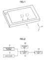
- FIG. 1 is a perspective view illustrating an exterior of a mobile device 1 according to the embodiment of the present invention.
- the mobile device 1 is a portable device such as a mobile game machine, a cellular phone, and a smart phone, and incorporates a magnetic sensor 2, and a gyroscope 3 as illustrated in FIG. 1 .
- the magnetic sensor 2 is a sensor for detecting a direction and a magnitude of magnetism.
- the magnetic sensor 2 is a three-axis sensor for detecting the magnitudes of magnetism in directions respectively along three reference axes orthogonal to each other and set to the mobile device 1 according to this embodiment.
- the magnetic sensor 2 is disposed in the mobile device 1 so that the three reference axes, namely, X axis, Y axis, and Z axis respectively coincide with the left/right direction, the up/down direction, and the depth direction of the mobile device 1.
- the magnetic sensor 2 outputs output data constructed by three output values (x M , y M , z M ) representing the magnitudes of the magnetism respectively along the three reference axes.
- the mobile device 1 can identify the direction of the geomagnetism using the output data of the magnetic sensor 2.
- the gyroscope 3 is a sensor for detecting angular velocities of rotations about predetermined reference axes.
- the gyroscope 3 is a three-axis sensor for detecting angular velocities of rotations about three reference axes as the magnetic sensor 2.
- the gyroscope 3 is disposed in the mobile device 1 so that the three reference axes thereof coincide with the three reference axes of the magnetic sensor 2.
- the mobile device 1 can acquire information on rotation angles by integrating the output of the gyroscope 3 when the mobile device 1 rotates. This information represents an amount of a change in the direction (posture) of the mobile device 1.
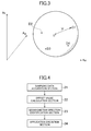
- FIG. 2 is a configuration block diagram illustrating an internal configuration of the mobile device 1.
- the mobile device 1 includes a control unit 11, a storage unit 12, and an output unit 13 as illustrated in FIG. 2 .
- the control unit 11 includes a CPU or the like, and carries out various types of information processing according to programs stored in the storage unit 12.
- the control unit 11 reads the output data from the magnetic sensor 2 and the gyroscope 3, and carries out calibration processing for the magnetic sensor 2 based on the data. Offset values of the magnetic sensor 2 acquired as a result of the calibration processing are stored in the storage unit 12, and are used for correcting the output data of the magnetic sensor 2.
- the storage unit 12 is constructed by a memory device such as a RAM and a ROM, and stores the programs executed by the control unit 11 and various types of data. Moreover, the storage unit 12 functions as a working memory for the control unit 11.
- the output unit 13 is an image display device such as a liquid crystal display, a speaker, or the like, and outputs a result of the processing carried out by the control unit 11.
- the output value for each of the reference axes of the magnetic sensor 2 is generally a sum of the magnitude of the magnetic field generated by the geomagnetism and the offset value.
- the offset value is a value output by the magnetic sensor 2 if there is no influence from the geomagnetism. For example, if the mobile device 1 is disposed so that any one of the reference axis is orthogonal to the direction of the geomagnetism, the magnitude of the geomagnetism in the direction of this reference axis is zero, and the output value for this reference axis of the magnetic sensor 2 coincides with the offset value.
- the offset values for the X axis, Y axis, and Z axis are respectively denoted by x 0 , y 0 , and z 0 . These offset values vary depending on operating environments of the magnetic sensor 2 such as the magnetic field and the temperature around the mobile device 1.
- the mobile device 1 carries out processing of periodically estimating the current offset values, and storing the estimated offset values in the storage unit 12. This processing is referred to as the calibration processing for the magnetic sensor 2 hereinafter.
- the mobile device 1 acquires the values representing the magnitudes of the magnetic field generated by the geomagnetism by respectively subtracting the offset values stored in the storage unit 12 from the output values for the reference axes of the magnetic sensor 2. As a result, the mobile device 1 can identify the direction of the geomagnetism with respect to the mobile device 1 itself.
- the offset values are estimated as mentioned below.
- the mobile device 1 acquires the output data of the magnetic sensor 2 as sampling data items D in a plurality of states in which the mobile device 1 is directed in directions different from one another.
- the sampling data item D is constructed by output values from the magnetic sensor 2 respectively for the X, Y, and Z axes.
- a virtual three-dimensional space having the output values (x M ,y M ,z M ) for the respective reference axes of the magnetic sensor 2 as coordinate axes is considered.
- This virtual three-dimensional space is referred to as output-value space of the magnetic sensor 2 hereinafter.
- the sampling data item D constructed by the three output values corresponds to one point in the output-value space.
- offset data constructed by a set of offset values for the respective reference axes (x 0 ,y 0 ,z 0 ) also corresponds to one point in the output-value space.
- a point in the output-value space corresponding to the offset data is referred to as reference point O hereinafter.
- geomagnetic vector V a vector representing the direction and the magnitude of the geomagnetism at a time point when the sampling data item D is acquired
- geomagnetic vector V the point corresponding to the sampling data item D in the output-value space of the magnetic sensor 2 must coincide with an end point of the geomagnetic vector V while the reference point O is set to a start point thereof.
- the mobile device 1 thus acquires a plurality of sampling data items D, and calculates a center point of a sphere on which respective points in the output-value space corresponding to these sampling data items D are present. It is estimated that this center point is a position of the reference point O.
- the mobile device 1 estimates the offset values by acquiring a plurality of sampling data items D and calculating a coordinate of a position of a point in the output-value space which is at an equal distance from any of points corresponding to these sampling data items D.
- At least four sampling data items D which are not on the same plane are necessary for uniquely determining a spherical surface in order to estimate the offset values.
- the offset values can be estimated more precisely as the number of the sampling data items D increases.
- FIG. 3 illustrates the output-value space, and illustrates a state in which points respectively corresponding to sampling data items D1 to D4 are positioned on the surface of a sphere the center of which is the reference point O corresponding to offset data.
- the plurality of sampling data items D used for estimating the offset value are preferably obtained in states in which the mobile device 1 is in directions separated from one another as much as possible. This is because the surface of the sphere cannot be precisely approximated only with sampling data items D obtained in directions relatively close to one another.
- the mobile device 1 according to this embodiment uses the gyroscope 3 as a sensor for detecting the posture of the mobile device 1 independently of the magnetic sensor 2, thereby determining timing for acquiring the sampling data item D used for calibrating the magnetic sensor 2.
- the mobile device 1 periodically acquires output data of the gyroscope 3, and acquires the output data of the magnetic sensor 2 as new sampling data item D in timing when it is determined from the acquired output data of the gyroscope 3 that the posture of the mobile device 1 has largely changed from when previous sampling data item D was acquired. Even if the user does not intentionally change the posture of the mobile device 1, the mobile device 1 can acquire the sampling data items D for the calibration in timing when the direction of the mobile device 1 naturally changes while the mobile device 1 is used by the user in this way.
- the mobile device 1 is functionally constructed by a sampling data acquisition section 21, an offset value calculation section 22, a geomagnetism direction identification section 23, and an application execution section 24. These functions are realized by the control unit 11 executing the programs stored in the storage unit 12.
- the sampling data acquisition section 21 acquires at least four sampling data items D for calibrating the magnetic sensor 2. Particularly, the sampling data acquisition section 21 periodically acquires the detection result by the gyroscope 3, and determines the timing for acquiring the sampling data items D based on the acquired detection result by the gyroscope 3. The sampling data acquisition section 21 determines whether or not the direction of the mobile device 1 has changed by a predetermined angle from a direction at a time point when the sampling data item D was previously acquired using the detection result by the gyroscope 3, for example. The sampling data acquisition section 21 then acquires the output data of the magnetic sensor 2 as new sampling data item D when the sampling data acquisition section 21 determines that the mobile device 1 has rotated by an angle equal to or more than the predetermined angle. The sampling data acquisition section 21 acquires at least four sampling data items D by repeating this processing.
- the offset value calculation section 22 calculates offset values (x 0 ,y 0 ,z 0 ) for the respective reference axes using the at least four sampling data items D acquired by the sampling data acquisition section 21, and stores the calculated offset values in the storage unit 12. Specifically, the offset value calculation section 22 calculates, as the offset values, coordinate values of the centerpoint of a sphere passing through points in the output-value space respectively corresponding to the plurality of sampling data items D. If the offset values previously calculated are stored in the storage unit 12, the offset value calculation section 22 updates the stored values with the newly calculated offset values.
- M 11 x 1 y 1 z 1 1 x 2 y 2 z 2 1 x 3 y 3 z 3 1 x 4 y 4 z 4 1 M ⁇ a ⁇ t ⁇ h .
- M 12 x 1 2 + y 1 2 + z 1 2 y 1 z 1 1 x 2 2 + y 2 2 + z 2 2 y 2 z 2 1 x 3 2 + y 3 2 + z 3 2 y 3 z 3 1 x 4 2 + y 4 2 + z 4 2 y 4 z 4 1 M ⁇ a ⁇ t ⁇ h .
- M 14 x 1 2 + y 1 2 + z 1 2 x 1 y 1 1 x 2 2 + y 2 2 + z 2 2 x 2 y 2 1 x 3 2 + y 3 2 + z 3 2 x 3 y 3 1 x 4 2 + y 4 2 + z 4 2 x 4 y 4 1 M ⁇ a ⁇ t ⁇ h .
- Equation (1) can be transformed into the following equation.
- M ⁇ a ⁇ t ⁇ h . 8 x - M 12 2 ⁇ M 11 2 + y + M 13 2 ⁇ M 11 2 + z - M 14 2 ⁇ M 11 2 M 12 2 ⁇ M 11 2 + M 13 2 ⁇ M 11 2 + M 14 2 ⁇ M 11 2 - M 15 M 11
- the offset values (x 0 ,y 0 ,z 0 ) corresponding to the position coordinate of the center of the sphere is calculated by the following equation.
- X 0 M 12 2 ⁇ M 11
- y 0 - M 13 2 ⁇ M 11
- z 0 M 14 2 ⁇ M 11
- the radius of the sphere corresponding to the magnitude of the geomagnetism is represented by the following equation.
- M ⁇ a ⁇ t ⁇ h . 10 r x 0 2 + y 0 2 + z 0 2 - M 15 M 11
- the geomagnetic identification section 23 identifies the direction of the geomagnetism with respect to the mobile device 1 by using the output result of the magnetic sensor 2 and the offset data stored in the storage unit 12 by the offset value calculation section 22, and outputs information on the identified direction.
- the application execution section 24 executes the application programs stored in the storage unit 12.
- the application execution section 24 carries out processing utilizing the direction of the geomagnetism output by the geomagnetism direction identification section 23, and outputs a result thereof to the output unit 13 .
- the application execution section 24 executes an application program for displaying a map, and changes the orientation of the map to be displayed in accordance with a change in the direction of the geomagnetism.
- the mobile device 1 acquires four sampling data items D1 to D4, and calculates the offset values using the sampling data items D1 to D4 in this processing.
- Vectors indicating directions of the mobile device 1 at time points when the four sampling data items D1 to D4 are respectively acquired are denoted by direction vectors q1 to q4 in the following description.
- the mobile device 1 stores a direction vector qc representing the current direction of the mobile device 1 in the storage unit 12 .
- These direction vectors represent relative directions of the mobile device 1 with respect to the direction of the mobile device 1 at a reference time point serving as a reference, and are calculated by integrating the detection result of the gyroscope 3 (namely, rotational angles about the respective reference axes of the mobile device 1 per unit time) with the reference time point as a start.
- These direction vectors are three-dimensional vectors pointing one direction in the three-dimensional space.
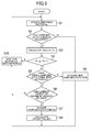
- the sampling data acquisition section 21 first acquires a current detection result by the gyroscope 3, and updates the current direction vector of the mobile device 1 based on the acquired detection result of the gyroscope 3 (S1). Specifically, the sampling data acquisition section 21 updates the information on the direction vector qc by changing the direction indicated by the direction vector qc stored in the storage unit 12 using the information on the rotation angle indicated by the detection result by the gyroscope 3.
- the angle ⁇ i between the direction vector qc and the direction vector qi can be calculated by obtaining an inner product of these vectors.
- the sampling data acquisition section 21 determines whether or not the calculated angles ⁇ i in the step S3 are equal to or more than a predetermined threshold ⁇ th (S4). If two or more sampling data items D have already been acquired and a plurality of angles ⁇ i have been calculated in S3, the sampling data acquisition section 21 determines whether or not all the angles are equal to or more than the threshold ⁇ th. For example, if three sampling data items D have already been acquired, for example, the sampling data acquisition section 21 determines whether or not all the angles ⁇ 1 to ⁇ 3 calculated in S3 are equal to or more than threshold ⁇ th.
- the current direction of the mobile device 1 is different by an angle equal to or more than the angle ⁇ th from any of the directions when the sampling data items D have previously been acquired. If the sampling data acquisition section 21 determines that at least one of the angles ⁇ i is less than the threshold ⁇ th, the sampling data acquisition section 21 determines not to use the output data of the magnetic sensor 2 at that time point as the sampling data item D.
- the sampling data acquisition section 21 determines whether or not three sampling data items D1-D3 have already been acquired (S5). If three sampling data items D1-D3 have already been acquired, the sampling data acquisition section 21 determines whether or not the current output data of the magnetic sensor 2 can be used as new sampling data item D4 (S6). Specifically, the sampling data acquisition section 21 determines that the output data cannot be used as the sampling data item D4 if the current output data of the magnetic sensor 2 and the three sampling data items D1-D3 already acquired are on the same plane in the output-value space. Otherwise, the current output data of the magnetic sensor 2 is acquired as new sampling data item D4 (S7). Then, the offset value calculation section 22 calculates new offset values using the four sampling data items D1-D4, and updates the offset values stored in the storage unit 12 with the newly calculated values (S8).
- the sampling data acquisition section 21 determines that the sampling data item D has not been acquired yet in S2, or that the number of the sampling data items D is less than three in S5, the sampling data acquisition section 21 acquires the current output data of the magnetic sensor 2 as new sampling data item Di unconditionally (S9).
- the sampling data acquisition section 21 stores the direction vector qc of the mobile device 1 at this time point as a direction vector qi corresponding to the sampling data item Di in the storage unit 12.
- the sampling data acquisition section 21 determines that the current output data of the magnetic sensor 2 cannot be used as the sampling data item D in S4 or S6, or the processing in S8 or S9 has been finished, the sampling data acquisition section 21 waits for elapse of a predetermined period (S10), returns to S1, and tries to acquire new sampling data item D.
- S10 a predetermined period
- the sampling data acquisition section 21 deletes the sampling data item D1 acquired least recently out of the four sampling data items D used for updating the offset values, sets the remaining sampling data items D2-D4 to new sampling data items D1-D3, and tries to acquire next sampling data item D4.
- the mobile device 1 can continue the update of the offset values using the latest sampling data items D by repeating this processing.
- the sampling data acquisition section 21 may not employ this output data as sampling data item D. This is because if a distance between any two of a plurality of sampling data items D in the output-value space is so close that the distance is equal to or less than the predetermined value, the offset values may not be precisely calculated.
- the offset value calculation section 22 may calculate an index value indicating reliability of newly calculated offset values (hereinafter, referred to as calculated offset values) based on the sampling data by means of the processing described above.
- the reliability of the calculated offset value is an index indicating how the calculated offset value is close to a true offset value (namely, actual output value of the magnetic sensor 2 if the geomagnetism is not present). For example, if the calculated offset value is largely different from the offset value which has been used previously, the offset value may be calculated using sampling data item D containing an error. The offset value calculation section 22 thus determines that the reliability of the calculated offset value is higher as the calculated offset value is closer to the offset value previously used.
- the offset value calculation section 22 may evaluate the reliability of the calculated offset values by comparing a change in the direction of the geomagnetism identified by the geomagnetism direction identification section 23 using the calculated offset values and a change in the direction of the mobile device 1 identified based on the detection result by the gyroscope 3.
- the change in the direction of the geomagnetism identified by the geomagnetism direction identification section 23 and the change in the direction of the mobile device 1 detected by the gyroscope 3 must usually coincide with each other.
- the estimation of the calculated offset values may not be correct, and it is estimated that the reliability of the calculated offset values is low.
- the offset value calculation section 22 may weight the calculated offset values in accordance with the indices of the reliability estimated in this way, thereby determining offset values (offset values after the update) actually used by the geomagnetism direction identification section 23 for identifying the direction of the geomagnetism. Specifically, if the reliability of the calculated offset values is low, the offset values stored in the storage unit 12 (offset values before the update) are not changed largely, and sets values which correspond to a position slightly close to the calculated offset values from the offset values before the update in the output-value space to the offset values after the update. Conversely, if the reliability of the calculated offset values is high, values closer than the offset values before the update to the calculated offset values are set to the offset values after the update. As a result, the offset values actually used for identifying the direction of the geomagnetism can be updated depending on the reliability of the calculated offset value.
- the offset value calculation section 22 may not update an offset value for a specific reference axis depending on the direction of the mobile device 1 when the sampling data acquisition section 21 acquires the sampling data items D. Specifically, if a rotation about a certain axis (axis of interest) is detected while rotations about the remaining two axes are not detected, the direction for the axis of interest is not changed. Information on the offset value of the axis of interest is not acquired in this case, the offset value for the axis of interest is not updated, and the offset values only for the other two axes are updated using the calculated offset values.
- the offset value calculation section 22 calculates information on amounts of rotation indicating how much the respective reference axes have rotated while acquiring a plurality of sampling data items D used for calculating the offset values.
- the information on the amounts of the rotation can be calculated by integrating the output of the gyroscope 3 for the respective axes.
- the output of the gyroscope 3 for the X axis indicates a rotation angle about the X axis, namely, respective amounts of rotation of the Y axis and Z axis orthogonal to the X axis
- the output of the gyroscope 3 for the Y axis indicates a rotation angle about the Y axis, namely, respective amounts of rotation of the X axis and Z axis orthogonal to the Y axis, for example.
- This means that the amount of rotation of the Z axis can be calculated from outputs of the gyroscope 3 for the X axis and Y axis.
- the amount of rotation of which acquired in this way is less than a predetermined value, it is considered that the direction of this reference axis has changed little, and the offset value for this reference axis is excluded from the subject of update.
- the offset value calculation section 22 may use the information on the amount of rotation for each of the reference axes for estimating the reliability described above. Specifically, for a reference axis the amount of rotation of which is small while the sampling data items D are acquired, the offset value calculation section 22 evaluates the reliability of the offset value calculated using the sampling data items D as low, and conversely, for a reference axis the amount of rotation of which is large, the offset value calculation section 22 evaluates the reliability of the offset value as high. If the amount of rotation of the Z axis is small, for example, the output for the Z axis of the magnetic sensor 2 has not changed largely, and it is thus considered that the reliability of the offset value z O of the Z axis is low. In this case, if each of the reference axes is weighted in accordance with the information on the reliability as described above, it is possible to prevent the offset value z O for the Z axis from largely changing from a value before the update.
- the offset value calculation section 22 may calculate detection sensitivity of the magnetic sensor 2 in addition to the offset values of the magnetic sensor 2 based on the detection result of the gyroscope 3. Specifically, if one reference axis is set to an axis of interest and it is determined that the axis of interest has rotated by 180 degrees or more from a direction coincident with the direction of the geomagnetism to a direction opposite to the direction of the geomagnetism, the output value of the magnetic sensor 2 during this rotation contains both the maximum value and the minimum value.
- the offset value calculation section 22 calculates a value of a parameter relating to the current sensitivity of the axis of interest using the maximum value and the minimum value, and updates a parameter stored in the storage unit 12 to the newly calculated value.
- the offset value calculation section 22 can update the parameter relating to the detection sensitivity using the output of the magnetic sensor 2 during the change.
- the geomagnetic direction identification section 23 may evaluate reliability of the identified direction of the geomagnetism using the detection result by the gyroscope 3.
- a change in direction of the geomagnetism and a change in the direction of the mobile device 1 detected by the gyroscope 3 must generally coincide with each other as described above. If a corresponding change in the output of the gyroscope 3 is not observed but the output of the magnetic sensor 2 changes while the offset values are not updated, it is estimated that the change in the output of the magnetic sensor 2 is not generated by the change in the direction of the geomagnetism as a result of a change in the direction of the mobile device 1 but by a change in a magnetic environment around the mobile device 1.
- the geomagnetism direction identification section 23 outputs, for the information on the direction of the geomagnetism identified by the current output value of the magnetic sensor 2, an index value indicating that the reliability thereof is low along therewith in this case. Conversely, if the detection result by the gyroscope 3 corresponding to a change in the direction of the geomagnetism is acquired, an index value indicating that the reliability of the information on the direction of the geomagnetism is high is output when the direction of the geomagnetism is identified.
- the application execution section 24 determines, by referring to the information on the reliability, to what degree the information on the direction of the geomagnetism identified by the geomagnetism direction identification section 23 is relied upon in the processing carried out by itself. For example, the application execution section 24 may ignore the information on the direction of the geomagnetism if it is determined that the reliability of the direction of the geomagnetism identified by the geomagnetism direction identification section 23 is low.
- the acquisition timing of the sampling data items D used for the calibration of the magnetic sensor 2 is determined based on the detection result of the gyroscope 3, and hence the sampling data items D allowing the precise calibration can be acquired compared with the case where the calibration is carried out only based on the output data of the magnetic sensor 2.
- the method of carrying out the calibration using only the output data of the magnetic sensor 2 maymisrecognize the variation of the magnetic field as variation of the geomagnetism caused by a change in the posture of the mobile device 1, and may carry out incorrect calibration.
- the detection result by the gyroscope 3 for detecting a change in the posture of the mobile device 1 independently of the magnetic sensor 2 is used according to this embodiment, and new sampling data item D can be surely acquired when a change in the posture of the mobile device 1 occurs.
- the embodiment described above is not the only embodiment of the present invention.
- the acquisition timing of the sampling data items D is determined based on the detection result by the gyroscope 3 in the above description, how to determine the acquisition timing is not limited to this case, and the mobile device 1 according to the embodiment of the present invention may determine the acquisition timing of the sampling data items D using another type of sensor for detecting the posture of the mobile device 1.
- the mobile device 1 according to the embodiment of the present invention may determine the acquisition timing of the sampling data items D using a detection result by an acceleration sensor for detecting a change in the direction of the gravitational acceleration.
Landscapes
- Engineering & Computer Science (AREA)
- General Engineering & Computer Science (AREA)
- Theoretical Computer Science (AREA)
- Physics & Mathematics (AREA)
- General Physics & Mathematics (AREA)
- Human Computer Interaction (AREA)
- Condensed Matter Physics & Semiconductors (AREA)
- Measuring Magnetic Variables (AREA)
Applications Claiming Priority (1)
| Application Number | Priority Date | Filing Date | Title |
|---|---|---|---|
| JP2011113370A JP5927776B2 (ja) | 2011-05-20 | 2011-05-20 | 携帯機器 |
Publications (3)
| Publication Number | Publication Date |
|---|---|
| EP2525274A2 true EP2525274A2 (de) | 2012-11-21 |
| EP2525274A3 EP2525274A3 (de) | 2015-11-11 |
| EP2525274B1 EP2525274B1 (de) | 2019-09-18 |
Family
ID=46229183
Family Applications (1)
| Application Number | Title | Priority Date | Filing Date |
|---|---|---|---|
| EP12168219.9A Active EP2525274B1 (de) | 2011-05-20 | 2012-05-16 | Mobile Vorrichtung mit einem Magnetfeldsensor und Verfahren zum Kalibrieren des Magnetfeldsensors |
Country Status (4)
| Country | Link |
|---|---|
| US (1) | US9164600B2 (de) |
| EP (1) | EP2525274B1 (de) |
| JP (1) | JP5927776B2 (de) |
| CN (1) | CN102798393B (de) |
Cited By (1)
| Publication number | Priority date | Publication date | Assignee | Title |
|---|---|---|---|---|
| CN111174807A (zh) * | 2019-10-11 | 2020-05-19 | 广东小天才科技有限公司 | 一种自动校准地磁传感器的方法及智能手表 |
Families Citing this family (14)
| Publication number | Priority date | Publication date | Assignee | Title |
|---|---|---|---|---|
| JP6071302B2 (ja) * | 2012-07-26 | 2017-02-01 | オリンパス株式会社 | キャリブレーション装置およびプログラム |
| US9939497B2 (en) | 2013-03-15 | 2018-04-10 | Intel Corporation | Dynamically calibrating magnetic sensors |
| KR102006029B1 (ko) * | 2013-07-24 | 2019-08-01 | 매그나칩 반도체 유한회사 | 방위각 계산장치 및 그 방법 |
| US9398456B2 (en) * | 2014-03-07 | 2016-07-19 | Apple Inc. | Electronic device with accessory-based transmit power control |
| US9983224B2 (en) | 2014-05-02 | 2018-05-29 | Qualcomm Incorporated | Motion direction determination and application |
| US10281484B2 (en) | 2014-05-02 | 2019-05-07 | Qualcomm Incorporated | Motion direction determination and application |
| US20150316577A1 (en) * | 2014-05-02 | 2015-11-05 | Qualcomm Incorporated | Motion direction determination and application |
| JP6357992B2 (ja) * | 2014-09-10 | 2018-07-18 | 富士通株式会社 | 電子機器及びキャリブレーションプログラム |
| CN105700041B (zh) * | 2016-01-20 | 2017-11-24 | 广东欧珀移动通信有限公司 | 一种磁传感器校准控制方法及用户终端 |
| CN107238808A (zh) * | 2016-03-29 | 2017-10-10 | 深圳市蓝魔数码科技有限公司 | 一种地磁校准定位装置 |
| US10058016B2 (en) * | 2016-09-22 | 2018-08-21 | Apple Inc. | Compensation of magnetic interference |
| CN111750895B (zh) * | 2019-07-31 | 2023-02-28 | 广东小天才科技有限公司 | 一种基于可穿戴设备的运动方向检测方法及可穿戴设备 |
| DE102022208698A1 (de) * | 2022-08-23 | 2024-02-29 | Robert Bosch Gesellschaft mit beschränkter Haftung | Auswertevorrichtung und Verfahren zum Betreiben einer mit einem Magnetsensor und mindestens einem Inertialsensor ausgestatteten Sensorik |
| CN118090034A (zh) * | 2024-01-29 | 2024-05-28 | 上汽通用五菱汽车股份有限公司 | 一种传感器数据处理方法、装置、电子设备以及存储介质 |
Family Cites Families (18)
| Publication number | Priority date | Publication date | Assignee | Title |
|---|---|---|---|---|
| EP0485132B1 (de) * | 1990-11-06 | 1996-03-06 | Fujitsu Ten Limited | Richtungssensor mit einem Erdmagnetismussensor und einem Drehgeschwindigkeitskreiselsensor und Navigationssystem, welches diesen Richtungssensor enthält |
| JPH05164560A (ja) * | 1991-12-17 | 1993-06-29 | Hitachi Cable Ltd | 方位センサ |
| US6842991B2 (en) * | 2002-07-31 | 2005-01-18 | Robert W. Levi | Gyro aided magnetic compass |
| US7057173B2 (en) * | 2004-01-05 | 2006-06-06 | Laser Technology, Inc. | Magnetoresistive (MR) sensor temperature compensation and magnetic cross-term reduction techniques utilizing selective set and reset gain measurements |
| JP2005265414A (ja) * | 2004-03-16 | 2005-09-29 | Citizen Watch Co Ltd | 電子方位計及び記録媒体 |
| EP1605232A3 (de) * | 2004-06-11 | 2010-12-29 | Yamaha Corporation | Verfahren und Vorrichtung zur Messung des magnetischen Offsets von geomagnetischen Sensoren und tragbares elektronisches Gerät |
| WO2006011238A1 (ja) * | 2004-07-29 | 2006-02-02 | Yamaha Corporation | 方位データ演算方法、方位センサユニットおよび携帯電子機器 |
| WO2006035505A1 (ja) * | 2004-09-29 | 2006-04-06 | C & N Inc | 磁気センサの制御方法、制御装置、および携帯端末装置 |
| US7421340B2 (en) * | 2005-02-28 | 2008-09-02 | Vectronix Ag | Method, apparatus and computer program for azimuth determination e.g. for autonomous navigation applications |
| WO2008008230A2 (en) * | 2006-07-10 | 2008-01-17 | Memsic, Inc. | A system for sensing yaw rate using a magnetic field sensor and portable electronic devices using the same |
| WO2008122904A2 (en) * | 2007-04-04 | 2008-10-16 | Nxp B.V. | Auto-calibration of orientation sensing system |
| JP5012252B2 (ja) * | 2007-06-25 | 2012-08-29 | ヤマハ株式会社 | 磁気データ処理装置、方法およびプログラム |
| JP5067155B2 (ja) | 2007-12-28 | 2012-11-07 | ヤマハ株式会社 | 磁気データ処理装置、ナビゲーション装置、磁気データ処理方法および磁気データ処理プログラム |
| JP5178226B2 (ja) | 2008-02-08 | 2013-04-10 | オリンパス株式会社 | 画像処理装置および画像処理プログラム |
| JP5168629B2 (ja) * | 2008-02-08 | 2013-03-21 | 旭化成エレクトロニクス株式会社 | 方位角計測装置及び方位角計測方法 |
| WO2010131599A1 (ja) * | 2009-05-14 | 2010-11-18 | 日本電気株式会社 | 携帯機器の地磁気センサの補正方法、携帯機器及びプログラム |
| US8437970B2 (en) * | 2009-06-05 | 2013-05-07 | Apple Inc. | Restoring and storing magnetometer calibration data |
| CN101806595B (zh) | 2010-04-19 | 2012-01-04 | 美新半导体(无锡)有限公司 | 一种两维电子指南针校准方法 |
-
2011
- 2011-05-20 JP JP2011113370A patent/JP5927776B2/ja active Active
-
2012
- 2012-05-16 EP EP12168219.9A patent/EP2525274B1/de active Active
- 2012-05-17 US US13/473,915 patent/US9164600B2/en active Active
- 2012-05-21 CN CN201210158375.1A patent/CN102798393B/zh active Active
Non-Patent Citations (1)
| Title |
|---|
| None |
Cited By (2)
| Publication number | Priority date | Publication date | Assignee | Title |
|---|---|---|---|---|
| CN111174807A (zh) * | 2019-10-11 | 2020-05-19 | 广东小天才科技有限公司 | 一种自动校准地磁传感器的方法及智能手表 |
| CN111174807B (zh) * | 2019-10-11 | 2022-05-27 | 广东小天才科技有限公司 | 一种自动校准地磁传感器的方法及智能手表 |
Also Published As
| Publication number | Publication date |
|---|---|
| US9164600B2 (en) | 2015-10-20 |
| US20120296596A1 (en) | 2012-11-22 |
| JP5927776B2 (ja) | 2016-06-01 |
| EP2525274B1 (de) | 2019-09-18 |
| EP2525274A3 (de) | 2015-11-11 |
| JP2012242267A (ja) | 2012-12-10 |
| CN102798393B (zh) | 2016-05-11 |
| CN102798393A (zh) | 2012-11-28 |
Similar Documents
| Publication | Publication Date | Title |
|---|---|---|
| EP2525274B1 (de) | Mobile Vorrichtung mit einem Magnetfeldsensor und Verfahren zum Kalibrieren des Magnetfeldsensors | |
| JP2012242267A5 (de) | ||
| JP5017539B1 (ja) | 地磁気を測定し、利用する応用機器 | |
| EP2662664B1 (de) | Systeme und Verfahren zur Auswahl einer Landmarke zur Navigation | |
| CN103221788B (zh) | 陀螺仪传感器的标定设备和方法 | |
| JP5469670B2 (ja) | 地磁気検出装置 | |
| CN103575293B (zh) | 一种磁力计方向角校正方法及磁力计 | |
| CN110319851B (zh) | 传感器的校正方法、装置、设备及存储介质 | |
| US20140150521A1 (en) | System and Method for Calibrating Inertial Measurement Units | |
| CN103941309A (zh) | 地磁传感器校准设备及其方法 | |
| US20150025838A1 (en) | Position estimation device, position estimation method, and integrated circuit | |
| US20220364882A1 (en) | Gyroscope Bias Estimation | |
| US20110218769A1 (en) | Magnetic data processing device, method, and program | |
| JP6119342B2 (ja) | 電子方位計、電子時計、電子方位計の補正タイミング検出方法、及び、プログラム | |
| US20150260543A1 (en) | Background calibration | |
| JP2017166895A (ja) | 電子機器及びセンサ較正方法、センサ較正プログラム | |
| WO2014115848A1 (ja) | 回転情報演算方法、回転情報演算プログラム、磁気型ジャイロスコープおよび移動体 | |
| JP5678748B2 (ja) | 端末装置及び地磁気環境判定プログラム | |
| JP6579478B2 (ja) | 電子機器及びセンサ較正方法、センサ較正プログラム | |
| JP6635285B2 (ja) | 電子機器及びセンサ較正方法、センサ較正プログラム | |
| JP5309373B2 (ja) | 電子コンパス | |
| JP6428824B2 (ja) | 電子方位計、電子時計、電子方位計の補正タイミング検出方法、及びプログラム | |
| Hemanth et al. | Calibration of 3-axis magnetometers | |
| WO2013005509A1 (ja) | 磁気式ジャイロ | |
| JP6146962B2 (ja) | 磁気データ処理装置 |
Legal Events
| Date | Code | Title | Description |
|---|---|---|---|
| PUAI | Public reference made under article 153(3) epc to a published international application that has entered the european phase |
Free format text: ORIGINAL CODE: 0009012 |
|
| 17P | Request for examination filed |
Effective date: 20120531 |
|
| AK | Designated contracting states |
Kind code of ref document: A2 Designated state(s): AL AT BE BG CH CY CZ DE DK EE ES FI FR GB GR HR HU IE IS IT LI LT LU LV MC MK MT NL NO PL PT RO RS SE SI SK SM TR |
|
| AX | Request for extension of the european patent |
Extension state: BA ME |
|
| PUAL | Search report despatched |
Free format text: ORIGINAL CODE: 0009013 |
|
| AK | Designated contracting states |
Kind code of ref document: A3 Designated state(s): AL AT BE BG CH CY CZ DE DK EE ES FI FR GB GR HR HU IE IS IT LI LT LU LV MC MK MT NL NO PL PT RO RS SE SI SK SM TR |
|
| AX | Request for extension of the european patent |
Extension state: BA ME |
|
| RIC1 | Information provided on ipc code assigned before grant |
Ipc: G01R 33/00 20060101ALI20151005BHEP Ipc: G06F 3/038 20130101AFI20151005BHEP Ipc: G06F 3/033 20130101ALI20151005BHEP Ipc: G01C 17/38 20060101ALI20151005BHEP |
|
| RAP1 | Party data changed (applicant data changed or rights of an application transferred) |
Owner name: SONY INTERACTIVE ENTERTAINMENT INC. |
|
| STAA | Information on the status of an ep patent application or granted ep patent |
Free format text: STATUS: EXAMINATION IS IN PROGRESS |
|
| 17Q | First examination report despatched |
Effective date: 20170206 |
|
| RAP1 | Party data changed (applicant data changed or rights of an application transferred) |
Owner name: SONY INTERACTIVE ENTERTAINMENT INC. |
|
| RIC1 | Information provided on ipc code assigned before grant |
Ipc: G06F 3/038 20130101AFI20190221BHEP Ipc: G06F 3/0346 20130101ALI20190221BHEP Ipc: G01C 17/38 20060101ALI20190221BHEP Ipc: G01R 33/00 20060101ALI20190221BHEP |
|
| GRAP | Despatch of communication of intention to grant a patent |
Free format text: ORIGINAL CODE: EPIDOSNIGR1 |
|
| STAA | Information on the status of an ep patent application or granted ep patent |
Free format text: STATUS: GRANT OF PATENT IS INTENDED |
|
| INTG | Intention to grant announced |
Effective date: 20190411 |
|
| GRAS | Grant fee paid |
Free format text: ORIGINAL CODE: EPIDOSNIGR3 |
|
| GRAA | (expected) grant |
Free format text: ORIGINAL CODE: 0009210 |
|
| STAA | Information on the status of an ep patent application or granted ep patent |
Free format text: STATUS: THE PATENT HAS BEEN GRANTED |
|
| AK | Designated contracting states |
Kind code of ref document: B1 Designated state(s): AL AT BE BG CH CY CZ DE DK EE ES FI FR GB GR HR HU IE IS IT LI LT LU LV MC MK MT NL NO PL PT RO RS SE SI SK SM TR |
|
| REG | Reference to a national code |
Ref country code: GB Ref legal event code: FG4D |
|
| REG | Reference to a national code |
Ref country code: CH Ref legal event code: EP |
|
| REG | Reference to a national code |
Ref country code: DE Ref legal event code: R096 Ref document number: 602012064048 Country of ref document: DE |
|
| REG | Reference to a national code |
Ref country code: AT Ref legal event code: REF Ref document number: 1182095 Country of ref document: AT Kind code of ref document: T Effective date: 20191015 |
|
| REG | Reference to a national code |
Ref country code: IE Ref legal event code: FG4D |
|
| REG | Reference to a national code |
Ref country code: NL Ref legal event code: MP Effective date: 20190918 |
|
| PG25 | Lapsed in a contracting state [announced via postgrant information from national office to epo] |
Ref country code: HR Free format text: LAPSE BECAUSE OF FAILURE TO SUBMIT A TRANSLATION OF THE DESCRIPTION OR TO PAY THE FEE WITHIN THE PRESCRIBED TIME-LIMIT Effective date: 20190918 Ref country code: LT Free format text: LAPSE BECAUSE OF FAILURE TO SUBMIT A TRANSLATION OF THE DESCRIPTION OR TO PAY THE FEE WITHIN THE PRESCRIBED TIME-LIMIT Effective date: 20190918 Ref country code: NO Free format text: LAPSE BECAUSE OF FAILURE TO SUBMIT A TRANSLATION OF THE DESCRIPTION OR TO PAY THE FEE WITHIN THE PRESCRIBED TIME-LIMIT Effective date: 20191218 Ref country code: BG Free format text: LAPSE BECAUSE OF FAILURE TO SUBMIT A TRANSLATION OF THE DESCRIPTION OR TO PAY THE FEE WITHIN THE PRESCRIBED TIME-LIMIT Effective date: 20191218 Ref country code: FI Free format text: LAPSE BECAUSE OF FAILURE TO SUBMIT A TRANSLATION OF THE DESCRIPTION OR TO PAY THE FEE WITHIN THE PRESCRIBED TIME-LIMIT Effective date: 20190918 Ref country code: SE Free format text: LAPSE BECAUSE OF FAILURE TO SUBMIT A TRANSLATION OF THE DESCRIPTION OR TO PAY THE FEE WITHIN THE PRESCRIBED TIME-LIMIT Effective date: 20190918 |
|
| REG | Reference to a national code |
Ref country code: LT Ref legal event code: MG4D |
|
| PG25 | Lapsed in a contracting state [announced via postgrant information from national office to epo] |
Ref country code: LV Free format text: LAPSE BECAUSE OF FAILURE TO SUBMIT A TRANSLATION OF THE DESCRIPTION OR TO PAY THE FEE WITHIN THE PRESCRIBED TIME-LIMIT Effective date: 20190918 Ref country code: RS Free format text: LAPSE BECAUSE OF FAILURE TO SUBMIT A TRANSLATION OF THE DESCRIPTION OR TO PAY THE FEE WITHIN THE PRESCRIBED TIME-LIMIT Effective date: 20190918 Ref country code: GR Free format text: LAPSE BECAUSE OF FAILURE TO SUBMIT A TRANSLATION OF THE DESCRIPTION OR TO PAY THE FEE WITHIN THE PRESCRIBED TIME-LIMIT Effective date: 20191219 Ref country code: AL Free format text: LAPSE BECAUSE OF FAILURE TO SUBMIT A TRANSLATION OF THE DESCRIPTION OR TO PAY THE FEE WITHIN THE PRESCRIBED TIME-LIMIT Effective date: 20190918 |
|
| REG | Reference to a national code |
Ref country code: AT Ref legal event code: MK05 Ref document number: 1182095 Country of ref document: AT Kind code of ref document: T Effective date: 20190918 |
|
| PG25 | Lapsed in a contracting state [announced via postgrant information from national office to epo] |
Ref country code: AT Free format text: LAPSE BECAUSE OF FAILURE TO SUBMIT A TRANSLATION OF THE DESCRIPTION OR TO PAY THE FEE WITHIN THE PRESCRIBED TIME-LIMIT Effective date: 20190918 Ref country code: NL Free format text: LAPSE BECAUSE OF FAILURE TO SUBMIT A TRANSLATION OF THE DESCRIPTION OR TO PAY THE FEE WITHIN THE PRESCRIBED TIME-LIMIT Effective date: 20190918 Ref country code: EE Free format text: LAPSE BECAUSE OF FAILURE TO SUBMIT A TRANSLATION OF THE DESCRIPTION OR TO PAY THE FEE WITHIN THE PRESCRIBED TIME-LIMIT Effective date: 20190918 Ref country code: PT Free format text: LAPSE BECAUSE OF FAILURE TO SUBMIT A TRANSLATION OF THE DESCRIPTION OR TO PAY THE FEE WITHIN THE PRESCRIBED TIME-LIMIT Effective date: 20200120 Ref country code: RO Free format text: LAPSE BECAUSE OF FAILURE TO SUBMIT A TRANSLATION OF THE DESCRIPTION OR TO PAY THE FEE WITHIN THE PRESCRIBED TIME-LIMIT Effective date: 20190918 Ref country code: IT Free format text: LAPSE BECAUSE OF FAILURE TO SUBMIT A TRANSLATION OF THE DESCRIPTION OR TO PAY THE FEE WITHIN THE PRESCRIBED TIME-LIMIT Effective date: 20190918 Ref country code: PL Free format text: LAPSE BECAUSE OF FAILURE TO SUBMIT A TRANSLATION OF THE DESCRIPTION OR TO PAY THE FEE WITHIN THE PRESCRIBED TIME-LIMIT Effective date: 20190918 Ref country code: ES Free format text: LAPSE BECAUSE OF FAILURE TO SUBMIT A TRANSLATION OF THE DESCRIPTION OR TO PAY THE FEE WITHIN THE PRESCRIBED TIME-LIMIT Effective date: 20190918 |
|
| PG25 | Lapsed in a contracting state [announced via postgrant information from national office to epo] |
Ref country code: SK Free format text: LAPSE BECAUSE OF FAILURE TO SUBMIT A TRANSLATION OF THE DESCRIPTION OR TO PAY THE FEE WITHIN THE PRESCRIBED TIME-LIMIT Effective date: 20190918 Ref country code: CZ Free format text: LAPSE BECAUSE OF FAILURE TO SUBMIT A TRANSLATION OF THE DESCRIPTION OR TO PAY THE FEE WITHIN THE PRESCRIBED TIME-LIMIT Effective date: 20190918 Ref country code: IS Free format text: LAPSE BECAUSE OF FAILURE TO SUBMIT A TRANSLATION OF THE DESCRIPTION OR TO PAY THE FEE WITHIN THE PRESCRIBED TIME-LIMIT Effective date: 20200224 Ref country code: SM Free format text: LAPSE BECAUSE OF FAILURE TO SUBMIT A TRANSLATION OF THE DESCRIPTION OR TO PAY THE FEE WITHIN THE PRESCRIBED TIME-LIMIT Effective date: 20190918 |
|
| REG | Reference to a national code |
Ref country code: DE Ref legal event code: R097 Ref document number: 602012064048 Country of ref document: DE |
|
| PLBE | No opposition filed within time limit |
Free format text: ORIGINAL CODE: 0009261 |
|
| STAA | Information on the status of an ep patent application or granted ep patent |
Free format text: STATUS: NO OPPOSITION FILED WITHIN TIME LIMIT |
|
| PG2D | Information on lapse in contracting state deleted |
Ref country code: IS |
|
| PG25 | Lapsed in a contracting state [announced via postgrant information from national office to epo] |
Ref country code: DK Free format text: LAPSE BECAUSE OF FAILURE TO SUBMIT A TRANSLATION OF THE DESCRIPTION OR TO PAY THE FEE WITHIN THE PRESCRIBED TIME-LIMIT Effective date: 20190918 Ref country code: IS Free format text: LAPSE BECAUSE OF FAILURE TO SUBMIT A TRANSLATION OF THE DESCRIPTION OR TO PAY THE FEE WITHIN THE PRESCRIBED TIME-LIMIT Effective date: 20200119 |
|
| 26N | No opposition filed |
Effective date: 20200619 |
|
| PG25 | Lapsed in a contracting state [announced via postgrant information from national office to epo] |
Ref country code: SI Free format text: LAPSE BECAUSE OF FAILURE TO SUBMIT A TRANSLATION OF THE DESCRIPTION OR TO PAY THE FEE WITHIN THE PRESCRIBED TIME-LIMIT Effective date: 20190918 |
|
| PG25 | Lapsed in a contracting state [announced via postgrant information from national office to epo] |
Ref country code: CH Free format text: LAPSE BECAUSE OF NON-PAYMENT OF DUE FEES Effective date: 20200531 Ref country code: LI Free format text: LAPSE BECAUSE OF NON-PAYMENT OF DUE FEES Effective date: 20200531 Ref country code: MC Free format text: LAPSE BECAUSE OF FAILURE TO SUBMIT A TRANSLATION OF THE DESCRIPTION OR TO PAY THE FEE WITHIN THE PRESCRIBED TIME-LIMIT Effective date: 20190918 |
|
| REG | Reference to a national code |
Ref country code: BE Ref legal event code: MM Effective date: 20200531 |
|
| PG25 | Lapsed in a contracting state [announced via postgrant information from national office to epo] |
Ref country code: LU Free format text: LAPSE BECAUSE OF NON-PAYMENT OF DUE FEES Effective date: 20200516 |
|
| PG25 | Lapsed in a contracting state [announced via postgrant information from national office to epo] |
Ref country code: IE Free format text: LAPSE BECAUSE OF NON-PAYMENT OF DUE FEES Effective date: 20200516 |
|
| PG25 | Lapsed in a contracting state [announced via postgrant information from national office to epo] |
Ref country code: BE Free format text: LAPSE BECAUSE OF NON-PAYMENT OF DUE FEES Effective date: 20200531 |
|
| PG25 | Lapsed in a contracting state [announced via postgrant information from national office to epo] |
Ref country code: TR Free format text: LAPSE BECAUSE OF FAILURE TO SUBMIT A TRANSLATION OF THE DESCRIPTION OR TO PAY THE FEE WITHIN THE PRESCRIBED TIME-LIMIT Effective date: 20190918 Ref country code: MT Free format text: LAPSE BECAUSE OF FAILURE TO SUBMIT A TRANSLATION OF THE DESCRIPTION OR TO PAY THE FEE WITHIN THE PRESCRIBED TIME-LIMIT Effective date: 20190918 Ref country code: CY Free format text: LAPSE BECAUSE OF FAILURE TO SUBMIT A TRANSLATION OF THE DESCRIPTION OR TO PAY THE FEE WITHIN THE PRESCRIBED TIME-LIMIT Effective date: 20190918 |
|
| PG25 | Lapsed in a contracting state [announced via postgrant information from national office to epo] |
Ref country code: MK Free format text: LAPSE BECAUSE OF FAILURE TO SUBMIT A TRANSLATION OF THE DESCRIPTION OR TO PAY THE FEE WITHIN THE PRESCRIBED TIME-LIMIT Effective date: 20190918 |
|
| P01 | Opt-out of the competence of the unified patent court (upc) registered |
Effective date: 20230519 |
|
| PGFP | Annual fee paid to national office [announced via postgrant information from national office to epo] |
Ref country code: DE Payment date: 20250423 Year of fee payment: 14 |
|
| PGFP | Annual fee paid to national office [announced via postgrant information from national office to epo] |
Ref country code: GB Payment date: 20250423 Year of fee payment: 14 |
|
| PGFP | Annual fee paid to national office [announced via postgrant information from national office to epo] |
Ref country code: FR Payment date: 20250423 Year of fee payment: 14 |