EP2525108B1 - Turbolader, insbesondere für einen Verbrennungsmotor - Google Patents
Turbolader, insbesondere für einen Verbrennungsmotor Download PDFInfo
- Publication number
- EP2525108B1 EP2525108B1 EP20110305620 EP11305620A EP2525108B1 EP 2525108 B1 EP2525108 B1 EP 2525108B1 EP 20110305620 EP20110305620 EP 20110305620 EP 11305620 A EP11305620 A EP 11305620A EP 2525108 B1 EP2525108 B1 EP 2525108B1
- Authority
- EP
- European Patent Office
- Prior art keywords
- rings
- rolling bearing
- sealing
- ring
- turbocharger
- Prior art date
- Legal status (The legal status is an assumption and is not a legal conclusion. Google has not performed a legal analysis and makes no representation as to the accuracy of the status listed.)
- Active
Links
- 238000002485 combustion reaction Methods 0.000 title description 6
- 238000007789 sealing Methods 0.000 claims description 75
- 238000005096 rolling process Methods 0.000 claims description 65
- 239000000314 lubricant Substances 0.000 claims description 15
- 239000002184 metal Substances 0.000 claims description 9
- 230000004323 axial length Effects 0.000 claims description 3
- 239000007789 gas Substances 0.000 description 5
- 239000010705 motor oil Substances 0.000 description 3
- 230000003068 static effect Effects 0.000 description 3
- 229920002994 synthetic fiber Polymers 0.000 description 3
- 229920001971 elastomer Polymers 0.000 description 2
- 239000000806 elastomer Substances 0.000 description 2
- 239000010687 lubricating oil Substances 0.000 description 2
- 238000003754 machining Methods 0.000 description 2
- 238000000465 moulding Methods 0.000 description 2
- 239000007787 solid Substances 0.000 description 2
- 238000007664 blowing Methods 0.000 description 1
- 230000006835 compression Effects 0.000 description 1
- 238000007906 compression Methods 0.000 description 1
- 238000001816 cooling Methods 0.000 description 1
- 230000009977 dual effect Effects 0.000 description 1
- 238000005242 forging Methods 0.000 description 1
- 239000004519 grease Substances 0.000 description 1
- 238000005461 lubrication Methods 0.000 description 1
- 238000004519 manufacturing process Methods 0.000 description 1
- 239000000463 material Substances 0.000 description 1
- 239000002923 metal particle Substances 0.000 description 1
- 239000003921 oil Substances 0.000 description 1
- 230000002028 premature Effects 0.000 description 1
- 238000003860 storage Methods 0.000 description 1
Images


Classifications
-
- F—MECHANICAL ENGINEERING; LIGHTING; HEATING; WEAPONS; BLASTING
- F16—ENGINEERING ELEMENTS AND UNITS; GENERAL MEASURES FOR PRODUCING AND MAINTAINING EFFECTIVE FUNCTIONING OF MACHINES OR INSTALLATIONS; THERMAL INSULATION IN GENERAL
- F16C—SHAFTS; FLEXIBLE SHAFTS; ELEMENTS OR CRANKSHAFT MECHANISMS; ROTARY BODIES OTHER THAN GEARING ELEMENTS; BEARINGS
- F16C33/00—Parts of bearings; Special methods for making bearings or parts thereof
- F16C33/30—Parts of ball or roller bearings
- F16C33/66—Special parts or details in view of lubrication
- F16C33/6603—Special parts or details in view of lubrication with grease as lubricant
- F16C33/6633—Grease properties or compositions, e.g. rheological properties
-
- F—MECHANICAL ENGINEERING; LIGHTING; HEATING; WEAPONS; BLASTING
- F01—MACHINES OR ENGINES IN GENERAL; ENGINE PLANTS IN GENERAL; STEAM ENGINES
- F01D—NON-POSITIVE DISPLACEMENT MACHINES OR ENGINES, e.g. STEAM TURBINES
- F01D25/00—Component parts, details, or accessories, not provided for in, or of interest apart from, other groups
- F01D25/16—Arrangement of bearings; Supporting or mounting bearings in casings
-
- F—MECHANICAL ENGINEERING; LIGHTING; HEATING; WEAPONS; BLASTING
- F01—MACHINES OR ENGINES IN GENERAL; ENGINE PLANTS IN GENERAL; STEAM ENGINES
- F01D—NON-POSITIVE DISPLACEMENT MACHINES OR ENGINES, e.g. STEAM TURBINES
- F01D25/00—Component parts, details, or accessories, not provided for in, or of interest apart from, other groups
- F01D25/18—Lubricating arrangements
- F01D25/183—Sealing means
-
- F—MECHANICAL ENGINEERING; LIGHTING; HEATING; WEAPONS; BLASTING
- F02—COMBUSTION ENGINES; HOT-GAS OR COMBUSTION-PRODUCT ENGINE PLANTS
- F02C—GAS-TURBINE PLANTS; AIR INTAKES FOR JET-PROPULSION PLANTS; CONTROLLING FUEL SUPPLY IN AIR-BREATHING JET-PROPULSION PLANTS
- F02C6/00—Plural gas-turbine plants; Combinations of gas-turbine plants with other apparatus; Adaptations of gas-turbine plants for special use
- F02C6/04—Gas-turbine plants providing heated or pressurised working fluid for other apparatus, e.g. without mechanical power output
- F02C6/10—Gas-turbine plants providing heated or pressurised working fluid for other apparatus, e.g. without mechanical power output supplying working fluid to a user, e.g. a chemical process, which returns working fluid to a turbine of the plant
- F02C6/12—Turbochargers, i.e. plants for augmenting mechanical power output of internal-combustion piston engines by increase of charge pressure
-
- F—MECHANICAL ENGINEERING; LIGHTING; HEATING; WEAPONS; BLASTING
- F16—ENGINEERING ELEMENTS AND UNITS; GENERAL MEASURES FOR PRODUCING AND MAINTAINING EFFECTIVE FUNCTIONING OF MACHINES OR INSTALLATIONS; THERMAL INSULATION IN GENERAL
- F16C—SHAFTS; FLEXIBLE SHAFTS; ELEMENTS OR CRANKSHAFT MECHANISMS; ROTARY BODIES OTHER THAN GEARING ELEMENTS; BEARINGS
- F16C19/00—Bearings with rolling contact, for exclusively rotary movement
- F16C19/02—Bearings with rolling contact, for exclusively rotary movement with bearing balls essentially of the same size in one or more circular rows
- F16C19/14—Bearings with rolling contact, for exclusively rotary movement with bearing balls essentially of the same size in one or more circular rows for both radial and axial load
- F16C19/18—Bearings with rolling contact, for exclusively rotary movement with bearing balls essentially of the same size in one or more circular rows for both radial and axial load with two or more rows of balls
- F16C19/181—Bearings with rolling contact, for exclusively rotary movement with bearing balls essentially of the same size in one or more circular rows for both radial and axial load with two or more rows of balls with angular contact
- F16C19/183—Bearings with rolling contact, for exclusively rotary movement with bearing balls essentially of the same size in one or more circular rows for both radial and axial load with two or more rows of balls with angular contact with two rows at opposite angles
- F16C19/184—Bearings with rolling contact, for exclusively rotary movement with bearing balls essentially of the same size in one or more circular rows for both radial and axial load with two or more rows of balls with angular contact with two rows at opposite angles in O-arrangement
-
- F—MECHANICAL ENGINEERING; LIGHTING; HEATING; WEAPONS; BLASTING
- F16—ENGINEERING ELEMENTS AND UNITS; GENERAL MEASURES FOR PRODUCING AND MAINTAINING EFFECTIVE FUNCTIONING OF MACHINES OR INSTALLATIONS; THERMAL INSULATION IN GENERAL
- F16C—SHAFTS; FLEXIBLE SHAFTS; ELEMENTS OR CRANKSHAFT MECHANISMS; ROTARY BODIES OTHER THAN GEARING ELEMENTS; BEARINGS
- F16C33/00—Parts of bearings; Special methods for making bearings or parts thereof
- F16C33/72—Sealings
- F16C33/76—Sealings of ball or roller bearings
- F16C33/78—Sealings of ball or roller bearings with a diaphragm, disc, or ring, with or without resilient members
- F16C33/7889—Sealings of ball or roller bearings with a diaphragm, disc, or ring, with or without resilient members mounted to an inner race and extending toward the outer race
-
- F—MECHANICAL ENGINEERING; LIGHTING; HEATING; WEAPONS; BLASTING
- F16—ENGINEERING ELEMENTS AND UNITS; GENERAL MEASURES FOR PRODUCING AND MAINTAINING EFFECTIVE FUNCTIONING OF MACHINES OR INSTALLATIONS; THERMAL INSULATION IN GENERAL
- F16C—SHAFTS; FLEXIBLE SHAFTS; ELEMENTS OR CRANKSHAFT MECHANISMS; ROTARY BODIES OTHER THAN GEARING ELEMENTS; BEARINGS
- F16C33/00—Parts of bearings; Special methods for making bearings or parts thereof
- F16C33/72—Sealings
- F16C33/76—Sealings of ball or roller bearings
- F16C33/78—Sealings of ball or roller bearings with a diaphragm, disc, or ring, with or without resilient members
- F16C33/7896—Sealings of ball or roller bearings with a diaphragm, disc, or ring, with or without resilient members with two or more discrete sealings arranged in series
-
- F—MECHANICAL ENGINEERING; LIGHTING; HEATING; WEAPONS; BLASTING
- F05—INDEXING SCHEMES RELATING TO ENGINES OR PUMPS IN VARIOUS SUBCLASSES OF CLASSES F01-F04
- F05D—INDEXING SCHEME FOR ASPECTS RELATING TO NON-POSITIVE-DISPLACEMENT MACHINES OR ENGINES, GAS-TURBINES OR JET-PROPULSION PLANTS
- F05D2220/00—Application
- F05D2220/40—Application in turbochargers
-
- F—MECHANICAL ENGINEERING; LIGHTING; HEATING; WEAPONS; BLASTING
- F16—ENGINEERING ELEMENTS AND UNITS; GENERAL MEASURES FOR PRODUCING AND MAINTAINING EFFECTIVE FUNCTIONING OF MACHINES OR INSTALLATIONS; THERMAL INSULATION IN GENERAL
- F16C—SHAFTS; FLEXIBLE SHAFTS; ELEMENTS OR CRANKSHAFT MECHANISMS; ROTARY BODIES OTHER THAN GEARING ELEMENTS; BEARINGS
- F16C2360/00—Engines or pumps
- F16C2360/23—Gas turbine engines
- F16C2360/24—Turbochargers
Definitions
- the present invention relates to the field of turbochargers, and in particular those used in combustion engines for automotive vehicles.
- Such a turbocharger is known from GB 1430864A .
- a turbocharger is used to enhance the combustion engine performance by blowing compressed air into the cylinders of said engine.
- a turbocharger generally comprises a housing, a shaft extending through an opening formed on the housing, a turbine wheel mounted on a first end portion of the shaft and located in an exhaust gases passage of the combustion engine, a compressor wheel mounted on an opposite second end portion of said shaft and located in an admission gases passage of the engine, and rolling bearings disposed between the shaft and the housing.
- the engine oil may be used for the lubrication of the rolling bearings.
- the delivery of engine oil is shut off. This causes a strong temperature increase of the residual oil located between the shaft and the rolling bearing near to the turbine wheel. The cooling of said rolling bearing is thus not satisfactory. Otherwise, the engine oil may contain foreign matter, for example small metal particles, thereby causing a premature wear of the rolling bearings.
- European patent application EP-A2-2 042 758 discloses a turbocharger comprising a tank for storing a specific lubricating oil for the rolling bearings, said tank being formed within the housing.
- a tube is provided between the storage tank and the space where are housed the rolling bearings to supply by capillary action the lubricating oil.
- One aim of the present invention is therefore to overcome the aforementioned drawbacks.
- turbocharger according to claim 1.
- the sealing rings may be annular.
- one of the inner and outer rings comprises two grooves inside which are mounted the sealing rings.
- the rolling bearing further comprises an additional sealing ring disposed radially between the inner and outer rings and axially between radial lateral surfaces of said rings situated on the turbine wheel side and one of said two sealing rings.
- the rolling bearing may further comprise an additional sealing ring disposed radially between the inner and outer rings and axially between radial lateral surfaces of said rings situated on the compressor wheel side and one of said two sealing rings.
- the resistance to high temperatures of the lubricant disposed into the closed space located on the turbine wheel side is higher than that of the lubricant disposed into the closed space located on the compressor wheel side.
- the sealing rings are made from metal.
- the turbocharger comprises only one rolling bearing.
- the axial length of the rolling bearing ranges between 60% and 90% of the axial dimension of the housing, and preferably ranges between 70% and 80%.
- the turbocharger comprises a housing 12, a shaft 14 extending along a longitudinal axis 14a through a cylindrical bore or opening 16 of the housing, a rolling bearing 18 mounted onto the shaft 14 and disposed into the opening 16, a turbine wheel 20 fixed at one end of the shaft 14 and a compressor wheel 22 fixed at an opposite end of said shaft.
- the turbocharger 10 also comprises a cap 24 fixed at an axial end of the housing 12.
- the axial length of the rolling bearing 18 ranges between 60% and 90% of the axial dimension of the opening 16 of the housing, and more precisely between 70% and 80%.
- the rolling bearing 18 comprises an inner ring 26 and an outer ring 28 between which are housed two rows of rolling elements 30 and 32, which in this case are balls, two annular cages 34, 36 respectively maintaining the circumferential spacing of the rolling elements 30, 32 and two annular sealing rings 38, 40.
- the axis 18a of the rolling bearing is coaxial with the axis 14a of the shaft of the turbocharger.
- the inner and outer rings 26, 28 are concentric and symmetric with respect to a transverse radial plane passing through the centre of the rolling bearing.
- the rings 26, 28 are of the solid type.
- a "solid ring” is to be understood as a ring obtained by machining with removal of material (by machining, grinding) from metal tube stock, bar stock, rough forgings and/or rolled blanks.
- the outer ring 28 comprises an outer cylindrical surface 28a mounted radially into contact with the opening 16 ( Figure 1 ) of the housing and delimited by opposite radial lateral surfaces 28b, 28c which respectively axially come into contact with the cap 24 and a radial shoulder of the housing 12.
- the outer ring 28 also comprises a bore 28d of cylindrical shape from which are formed toroidal raceways 28e, 28f having in cross-section a concave internal profile adapted to the rolling elements 30, 32.
- the raceways 28e, 28f are symmetrical with respect to the transverse radial plane passing through the centre of the rolling bearing.
- the inner ring 26 is made in two parts which are identical, symmetrical with respect to the transverse radial plane of symmetry of the rolling bearing and mounted axially fixedly one against the other.
- the inner ring 26 is here composed of two identical half-rings. Alternatively, the inner ring may be made into one part.
- the inner ring 26 has a bore 26a of cylindrical shape into which the shaft 14 ( Figure 1 ) is mounted. Said bore is delimited by opposite radial lateral surfaces 26b and 26c, which are respectively coplanar with the lateral surfaces 28b, 28c of the outer ring.
- the radial surface 26c axially bears against a radial shoulder of the shaft 14.
- the inner ring 26 also comprises an exterior cylindrical surface 26d onto which first and second toroidal circular raceways 26e, 26f are formed.
- the said raceways have in cross-section a concave internal profile adapted to the rolling elements 30 and 32, the said raceways being directed radially outwards.
- the raceways 26e, 26f are symmetrical with respect to the transverse radial plane passing through the centre of the rolling bearing.
- the inner ring 26 also comprises two annular grooves 26g, 26h formed radially towards the inside from the exterior surface 26d, respectively in the vicinity of the radial surfaces 26b, 26c.
- the grooves 26g, 26h are symmetrical with one another relative to the transverse radial plane of symmetry of the rolling bearing. Inside the grooves 26g, 26h are fixedly mounted the annular sealing rings 38, 40.
- the sealing rings 38, 40 are identical to one another and apply a static sealing with the inner ring 26 and a dynamic sealing with the outer ring 28.
- the sealing rings 38, 40 are made from metal, advantageously from a thin metal sheet blank. Alternatively, the sealing rings may be made by moulding a synthetic material such as an elastomer.
- the sealing rings 38, 40 are continuous in the circumferential direction. To facilitate their fitting into the grooves 26g, 26h of the inner ring, each of the sealing rings may alternatively be open at a point of its circumference.
- the sealing rings have a flat washer shape. It should be understood that it is possible to foresee a different shape, for example a L-shaped section.
- the sealing rings 38, 40 are disposed radially between the inner and outer rings 26, 28. Each sealing ring 38, 40 extends radially towards the outer ring 28 and comes into sliding contact with the bore 28d of said ring. Alternatively, the sealing rings may remain at a small distance from said bore.
- the sealing ring 38 is axially situated on the compressor wheel side and the sealing ring 40 on the turbine wheel side.
- the sealing ring 38 is located axially between the row of rolling elements 30 and the radial surfaces 26b, 28b of the inner and outer rings, the sealing ring 40 being mounted axially between the row of rolling elements 32 and the radial surfaces 26c, 28c of said rings.
- a closed space 42 is defined between the rings 26, 28 and the sealing rings 38, 40 in which the rolling elements 30, 32 and the associated cages 34, 36 are housed so as to be protected against external polluting elements.
- the closed space 42 is delimited radially by the exterior surface 26d of the inner ring and the bore 28d of the outer ring, and axially by the radial sealing rings 38, 40.
- the closed space 42 is advantageously filled with a lubricant 44, such as grease, to increase the overall sealing of the rolling bearing.
- a lubricant 44 such as grease
- the sealing rings 38, 40 have a dual function, namely to prevent ingress of undesirable external polluting elements into the rolling bearing 18 and to keep the lubricant 44 inside the closed space 42 to obtain a sealed rolling bearing 18 with its own lubricant.
- the turbocharger 10 is further provided with a sealing ring 46 mounted radially between the shaft 14 and the cap 24 and axially disposed between the compressor wheel 22 and the rolling bearing 18, and with two sealing rings 48, 50 disposed radially between the shoulder of said shaft 14 and the opening 16 of housing and axially mounted between the rolling bearing 18 and the turbine wheel 20.
- the sealing rings 46 to 50 are fitted into grooves (not referenced) provided on the exterior surface of the shaft 14 and come into sliding contact with the cap 24 or the housing 12.
- the sealing rings 46 to 50 may be made from metal.
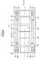
- the rolling bearing 18 of the turbocharger may further comprise an additional sealing ring 52 disposed radially between the inner and outer rings 26, 28 and axially between the radial surfaces 26c, 28c of said rings situated on the turbine wheel side and the sealing ring 40.
- the sealing ring 52 is fitted into an annular groove 26i formed on the exterior surface 26d of the inner ring, extends radially towards the outer ring 28 and comes into sliding contact with the cylindrical bore 28d of said ring.
- the sealing ring 52 is made from metal or synthetic material.
- the rolling bearing 18 of the turbocharger further comprises an additional sealing ring 54 disposed radially between the inner and outer rings 26, 28 and axially between the radial surfaces 26b, 28b of said rings situated on the compressor wheel side and the sealing ring 38.
- the sealing ring 54 is fitted into an annular groove 26j formed on the exterior surface 26d of the inner ring.
- the sealing rings 52, 54 are identical and symmetrical with one another relative to the transverse radial plane passing through the centre of the rolling bearing.
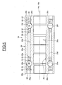
- the rolling bearing 18 of the turbocharger disclosed in the embodiment shown on Figure 5 differs from the first example in that it further comprises inner sealing rings 56, 58 disposed radially between the inner and outer rings 26, 28 and each delimiting together with said rings and the corresponding outer sealing ring 38, 40 a closed space 60, 62 for each row of rolling elements 30, 32.
- the sealing rings 56, 58 are identical to one another and apply a static sealing with the inner ring 26 and a dynamic sealing with the outer ring 28.
- the sealing ring 56, 58 are made from metal, advantageously from a thin metal sheet blank. Alternatively, the sealing rings may be made by moulding a synthetic material such as elastomer.
- the sealing rings 56, 58 are continuous in the circumferential direction. To facilitate their mounting, each of the sealing rings may alternatively be open at a point of its circumference.
- the sealing ring 56 is disposed near the cage 34 axially on the opposite side to the sealing ring 38 with regard to the row of rolling elements 30.
- the sealing ring 56 is fitted into an annular groove 26k provided on the exterior surface 26d of inner ring, extends radially towards the outer ring 28 and comes in sliding contact with the bore 28d of said ring. Alternatively, the sealing ring 56 may remain at a small distance from said bore.
- the axial distance between the inner sealing ring 56 and the row of rolling elements 30 is substantially equal to the one between said row and the outer sealing ring 38.
- the sealing ring 58 is fitted into a groove 261 provided on the exterior surface 26d of the inner ring and is symmetrical to the sealing ring 56 with regard to the radial transverse plane passing through the centre of the rolling bearing.
- each row of rolling elements 30 and 32 there is a sealing ring on each of the opposite sides of said row in order to close the radial space existing between the inner and outer ring and to define the associated closed space 60, 62 in which said row of rolling elements and the associated cage are housed.
- one sealing ring is positioned axially on the opposite side to the other with regard to said row.
- Each closed space 60, 62 is filled with a lubricant 64, 66.
- the associated sealing rings 38, 56 and 40, 58 prevent ingress of foreign matter and keep the lubricant inside the space where said rolling elements contact the raceways of the inner and outer rings.
- the quantity of lubricant into the rolling bearing 18 is reduced around 50% with regard to the previous examples.
- the lubricants 64, 66 may be different from each other.
- the lubricant 66 disposed into the closed space 62 axially located on the side of the turbine wheel has a resistance to high temperatures higher than the one of the lubricant 64. "High temperatures" are to be understood as temperatures at which is exposed the turbine wheel driven by the exhaust gases. These temperatures may reach for instance 1000° C.
- each of the sealing rings is mounted on the inner ring of the rolling bearing.
- the sealing rings may be disposed on the outer ring and thus apply a static sealing with said ring and a dynamic sealing with the inner ring.
- the invention applies not only to turbocharger comprising an angular contact ball rolling bearing with a double rows of balls but also to turbocharger comprising other types of rolling bearing, for example rolling bearing having four points contact and/or with at least three rows of balls.
Landscapes
- Engineering & Computer Science (AREA)
- General Engineering & Computer Science (AREA)
- Mechanical Engineering (AREA)
- Chemical & Material Sciences (AREA)
- Chemical Kinetics & Catalysis (AREA)
- General Chemical & Material Sciences (AREA)
- Combustion & Propulsion (AREA)
- Rolling Contact Bearings (AREA)
- Supercharger (AREA)
Claims (9)
- Turbolader, der eine Welle (14), ein Gehäuse (12), ein Turbinenrad (20) und ein Verdichterrad (22), die auf der Welle montiert sind, sowie mindestens ein Wälzlager (18) umfasst, das sich zwischen der Welle und dem Gehäuse befindet und einen Innenring (26), einen Außenring (28) sowie mindestens zwei Reihen Wälzkörper (30, 32) umfasst, die sich zwischen den Ringen befinden, dadurch gekennzeichnet, dass das Wälzlager weiterhin für jede Reihe Wälzkörper (30, 32) mindestens zwei Dichtringe (38, 56, 40, 58) umfasst, die sich radial zwischen den Innen- und Außenringen auf beiden Seiten einer jeden Reihe Wälzkörper befinden und zusammen mit den Ringen einen geschlossenen Raum (60, 62) begrenzen, in dem jede der Reihen Wälzkörper untergebracht ist, wobei jeder geschlossene Raum (60, 62) mit einem Schmiermittel (64, 66) befüllt ist und sich die Schmiermittel (64, 66) voneinander unterscheiden.
- Turbolader nach Anspruch 1, bei dem die Dichtringe (38, 56, 40, 58) ringförmig sind.
- Turbolader nach Anspruch 1 oder 2, bei dem einer der Innen- und Außenringe vier Nuten (26g, 26h, 26k, 261) umfasst, in denen die Dichtringe (38, 40, 56, 58) montiert sind.
- Turbolader nach einem der vorstehend aufgeführten Ansprüche, bei dem das Wälzlager weiterhin einen zusätzlichen Dichtring (52) umfasst, der sich radial zwischen den Innen- und Außenringen (26, 28) und axial zwischen radialen Seitenflächen (26c, 28c) der Ringe auf der Turbinenradseite und einem der zwei Dichtringe (38, 40) befindet.
- Turbolader nach einem der vorstehend aufgeführten Ansprüche, bei dem das Wälzlager weiterhin einen zusätzlichen Dichtring (54) umfasst, der sich radial zwischen den Innen- und Außenringen (26, 28) und axial zwischen radialen Seitenflächen (26b, 28b) der Ringe auf der Verdichterseite und einem der zwei Dichtringe (38, 40) befindet.
- Turbolader nach einem der vorstehend aufgeführten Ansprüche, bei dem die Hochtemperaturbeständigkeit des Schmiermittels (66), das sich im geschlossenen Raum (62) auf der Seite des Turbinenrads (20) befindet, höher als diejenige des Schmiermittels (64) ist, das sich im geschlossenen Raum (60) auf der Verdichterradseite befindet.
- Turbolader nach einem der vorstehend aufgeführten Ansprüche, bei dem die Dichtringe aus Metall bestehen.
- Turbolader nach einem der vorstehend aufgeführten Ansprüche, der nur ein Wälzlager (18) umfasst.
- Turbolader nach Anspruch 8, bei dem die axiale Länge des Wälzlagers (18) in einem Bereich von 60% bis 90% der axialen Abmessung des Gehäuses (12) und vorzugsweise in einem Bereich von 70% bis 80% liegt.
Priority Applications (1)
| Application Number | Priority Date | Filing Date | Title |
|---|---|---|---|
| EP20110305620 EP2525108B1 (de) | 2011-05-20 | 2011-05-20 | Turbolader, insbesondere für einen Verbrennungsmotor |
Applications Claiming Priority (1)
| Application Number | Priority Date | Filing Date | Title |
|---|---|---|---|
| EP20110305620 EP2525108B1 (de) | 2011-05-20 | 2011-05-20 | Turbolader, insbesondere für einen Verbrennungsmotor |
Publications (2)
| Publication Number | Publication Date |
|---|---|
| EP2525108A1 EP2525108A1 (de) | 2012-11-21 |
| EP2525108B1 true EP2525108B1 (de) | 2014-07-16 |
Family
ID=44510824
Family Applications (1)
| Application Number | Title | Priority Date | Filing Date |
|---|---|---|---|
| EP20110305620 Active EP2525108B1 (de) | 2011-05-20 | 2011-05-20 | Turbolader, insbesondere für einen Verbrennungsmotor |
Country Status (1)
| Country | Link |
|---|---|
| EP (1) | EP2525108B1 (de) |
Family Cites Families (5)
| Publication number | Priority date | Publication date | Assignee | Title |
|---|---|---|---|---|
| GB1430864A (en) * | 1973-04-06 | 1976-04-07 | Woollenweber W E | Rotatable assembly including two vaned wheels mounted on a common shaft |
| JPS62278315A (ja) * | 1986-05-24 | 1987-12-03 | Koyo Seiko Co Ltd | 軸受装置 |
| EP1719927A4 (de) * | 2004-02-18 | 2007-09-26 | Jtekt Corp | Wälzlager für auflader |
| JP4715336B2 (ja) * | 2005-06-28 | 2011-07-06 | 株式会社ジェイテクト | ターボチャージャー用軸受装置およびターボチャージャー |
| JP2009079628A (ja) | 2007-09-25 | 2009-04-16 | Jtekt Corp | 転がり軸受装置及びこれを用いた過給機 |
-
2011
- 2011-05-20 EP EP20110305620 patent/EP2525108B1/de active Active
Also Published As
| Publication number | Publication date |
|---|---|
| EP2525108A1 (de) | 2012-11-21 |
Similar Documents
| Publication | Publication Date | Title |
|---|---|---|
| EP2535526B1 (de) | Turbolader, insbesondere für einen Verbrennungsmotor | |
| EP2565393B1 (de) | Turbolader mit Isolierhuelse zwischen inneren Lagerring und Welle | |
| CN105889316B (zh) | 轴承装置 | |
| US8464680B2 (en) | Disengageable module for a system for transmitting a starting torque to an internal combustion engine | |
| JP2014202341A (ja) | 円すいころ軸受 | |
| US20150110427A1 (en) | Rolling bearing assembly having magnetic and/or electronic elements | |
| WO2012114726A1 (ja) | 複列アンギュラ玉軸受 | |
| US20130224015A1 (en) | Turbocharger, notably for a combustion engine | |
| US8632253B2 (en) | Bearing unit of a shaft of a pressure generating device | |
| EP2535607B1 (de) | Turbolader, insbesondere für einen Verbrennungsmotor | |
| JP2015148241A (ja) | 玉軸受用保持器及び玉軸受 | |
| EP2525108B1 (de) | Turbolader, insbesondere für einen Verbrennungsmotor | |
| JP5762698B2 (ja) | 分割型ニードル軸受及び軸受装置 | |
| EP2535608A1 (de) | Wälzlager, insbesondere für einen Turbolader | |
| CN104204565A (zh) | 包括弹性可变形元件的滚动轴承组件及其制造方法 | |
| EP2535609B1 (de) | Turbolader, insbesondere für einen Verbrennungsmotor | |
| WO2011142240A1 (ja) | 分割型ニードル軸受及び内燃機関の潤滑装置 | |
| US20130084034A1 (en) | Bearing with high-load radial and axial capabilites including a thermal compensation element as needed | |
| CN103403378A (zh) | 具有至少一个柔性圈的滚动轴承 | |
| US10697322B2 (en) | Turbocharger, notably for a combustion engine | |
| US20170044972A1 (en) | Bearing housing body assembly of an exhaust-gas turbocharger | |
| CN206175473U (zh) | 一种高密闭润滑抗轴向大载荷滚动轴承 | |
| US20210222766A1 (en) | Pulley device for a tensioner roller or winding roller | |
| US20090260517A1 (en) | Engine piston with rolling element skirt | |
| CN102135132A (zh) | 滚动轴承 |
Legal Events
| Date | Code | Title | Description |
|---|---|---|---|
| PUAI | Public reference made under article 153(3) epc to a published international application that has entered the european phase |
Free format text: ORIGINAL CODE: 0009012 |
|
| AK | Designated contracting states |
Kind code of ref document: A1 Designated state(s): AL AT BE BG CH CY CZ DE DK EE ES FI FR GB GR HR HU IE IS IT LI LT LU LV MC MK MT NL NO PL PT RO RS SE SI SK SM TR |
|
| AX | Request for extension of the european patent |
Extension state: BA ME |
|
| 17P | Request for examination filed |
Effective date: 20130408 |
|
| RIC1 | Information provided on ipc code assigned before grant |
Ipc: F02C 6/12 20060101ALN20131120BHEP Ipc: F01D 25/16 20060101ALI20131120BHEP Ipc: F16C 33/78 20060101ALI20131120BHEP Ipc: F16C 33/66 20060101ALI20131120BHEP Ipc: F16C 19/18 20060101AFI20131120BHEP Ipc: F01D 25/18 20060101ALI20131120BHEP |
|
| GRAP | Despatch of communication of intention to grant a patent |
Free format text: ORIGINAL CODE: EPIDOSNIGR1 |
|
| INTG | Intention to grant announced |
Effective date: 20140109 |
|
| GRAS | Grant fee paid |
Free format text: ORIGINAL CODE: EPIDOSNIGR3 |
|
| GRAA | (expected) grant |
Free format text: ORIGINAL CODE: 0009210 |
|
| AK | Designated contracting states |
Kind code of ref document: B1 Designated state(s): AL AT BE BG CH CY CZ DE DK EE ES FI FR GB GR HR HU IE IS IT LI LT LU LV MC MK MT NL NO PL PT RO RS SE SI SK SM TR |
|
| REG | Reference to a national code |
Ref country code: GB Ref legal event code: FG4D |
|
| REG | Reference to a national code |
Ref country code: CH Ref legal event code: EP |
|
| REG | Reference to a national code |
Ref country code: IE Ref legal event code: FG4D |
|
| REG | Reference to a national code |
Ref country code: AT Ref legal event code: REF Ref document number: 677844 Country of ref document: AT Kind code of ref document: T Effective date: 20140815 |
|
| REG | Reference to a national code |
Ref country code: DE Ref legal event code: R096 Ref document number: 602011008378 Country of ref document: DE Effective date: 20140904 |
|
| REG | Reference to a national code |
Ref country code: NL Ref legal event code: VDEP Effective date: 20140716 |
|
| REG | Reference to a national code |
Ref country code: AT Ref legal event code: MK05 Ref document number: 677844 Country of ref document: AT Kind code of ref document: T Effective date: 20140716 |
|
| REG | Reference to a national code |
Ref country code: LT Ref legal event code: MG4D |
|
| PG25 | Lapsed in a contracting state [announced via postgrant information from national office to epo] |
Ref country code: ES Free format text: LAPSE BECAUSE OF FAILURE TO SUBMIT A TRANSLATION OF THE DESCRIPTION OR TO PAY THE FEE WITHIN THE PRESCRIBED TIME-LIMIT Effective date: 20140716 Ref country code: PT Free format text: LAPSE BECAUSE OF FAILURE TO SUBMIT A TRANSLATION OF THE DESCRIPTION OR TO PAY THE FEE WITHIN THE PRESCRIBED TIME-LIMIT Effective date: 20141117 Ref country code: BG Free format text: LAPSE BECAUSE OF FAILURE TO SUBMIT A TRANSLATION OF THE DESCRIPTION OR TO PAY THE FEE WITHIN THE PRESCRIBED TIME-LIMIT Effective date: 20141016 Ref country code: LT Free format text: LAPSE BECAUSE OF FAILURE TO SUBMIT A TRANSLATION OF THE DESCRIPTION OR TO PAY THE FEE WITHIN THE PRESCRIBED TIME-LIMIT Effective date: 20140716 Ref country code: NO Free format text: LAPSE BECAUSE OF FAILURE TO SUBMIT A TRANSLATION OF THE DESCRIPTION OR TO PAY THE FEE WITHIN THE PRESCRIBED TIME-LIMIT Effective date: 20141016 Ref country code: SE Free format text: LAPSE BECAUSE OF FAILURE TO SUBMIT A TRANSLATION OF THE DESCRIPTION OR TO PAY THE FEE WITHIN THE PRESCRIBED TIME-LIMIT Effective date: 20140716 Ref country code: FI Free format text: LAPSE BECAUSE OF FAILURE TO SUBMIT A TRANSLATION OF THE DESCRIPTION OR TO PAY THE FEE WITHIN THE PRESCRIBED TIME-LIMIT Effective date: 20140716 Ref country code: GR Free format text: LAPSE BECAUSE OF FAILURE TO SUBMIT A TRANSLATION OF THE DESCRIPTION OR TO PAY THE FEE WITHIN THE PRESCRIBED TIME-LIMIT Effective date: 20141017 |
|
| PG25 | Lapsed in a contracting state [announced via postgrant information from national office to epo] |
Ref country code: RS Free format text: LAPSE BECAUSE OF FAILURE TO SUBMIT A TRANSLATION OF THE DESCRIPTION OR TO PAY THE FEE WITHIN THE PRESCRIBED TIME-LIMIT Effective date: 20140716 Ref country code: IS Free format text: LAPSE BECAUSE OF FAILURE TO SUBMIT A TRANSLATION OF THE DESCRIPTION OR TO PAY THE FEE WITHIN THE PRESCRIBED TIME-LIMIT Effective date: 20141116 Ref country code: CY Free format text: LAPSE BECAUSE OF FAILURE TO SUBMIT A TRANSLATION OF THE DESCRIPTION OR TO PAY THE FEE WITHIN THE PRESCRIBED TIME-LIMIT Effective date: 20140716 Ref country code: AT Free format text: LAPSE BECAUSE OF FAILURE TO SUBMIT A TRANSLATION OF THE DESCRIPTION OR TO PAY THE FEE WITHIN THE PRESCRIBED TIME-LIMIT Effective date: 20140716 Ref country code: NL Free format text: LAPSE BECAUSE OF FAILURE TO SUBMIT A TRANSLATION OF THE DESCRIPTION OR TO PAY THE FEE WITHIN THE PRESCRIBED TIME-LIMIT Effective date: 20140716 Ref country code: PL Free format text: LAPSE BECAUSE OF FAILURE TO SUBMIT A TRANSLATION OF THE DESCRIPTION OR TO PAY THE FEE WITHIN THE PRESCRIBED TIME-LIMIT Effective date: 20140716 Ref country code: LV Free format text: LAPSE BECAUSE OF FAILURE TO SUBMIT A TRANSLATION OF THE DESCRIPTION OR TO PAY THE FEE WITHIN THE PRESCRIBED TIME-LIMIT Effective date: 20140716 |
|
| REG | Reference to a national code |
Ref country code: DE Ref legal event code: R097 Ref document number: 602011008378 Country of ref document: DE |
|
| PG25 | Lapsed in a contracting state [announced via postgrant information from national office to epo] |
Ref country code: CZ Free format text: LAPSE BECAUSE OF FAILURE TO SUBMIT A TRANSLATION OF THE DESCRIPTION OR TO PAY THE FEE WITHIN THE PRESCRIBED TIME-LIMIT Effective date: 20140716 Ref country code: SK Free format text: LAPSE BECAUSE OF FAILURE TO SUBMIT A TRANSLATION OF THE DESCRIPTION OR TO PAY THE FEE WITHIN THE PRESCRIBED TIME-LIMIT Effective date: 20140716 Ref country code: IT Free format text: LAPSE BECAUSE OF FAILURE TO SUBMIT A TRANSLATION OF THE DESCRIPTION OR TO PAY THE FEE WITHIN THE PRESCRIBED TIME-LIMIT Effective date: 20140716 Ref country code: RO Free format text: LAPSE BECAUSE OF FAILURE TO SUBMIT A TRANSLATION OF THE DESCRIPTION OR TO PAY THE FEE WITHIN THE PRESCRIBED TIME-LIMIT Effective date: 20140716 Ref country code: DK Free format text: LAPSE BECAUSE OF FAILURE TO SUBMIT A TRANSLATION OF THE DESCRIPTION OR TO PAY THE FEE WITHIN THE PRESCRIBED TIME-LIMIT Effective date: 20140716 Ref country code: EE Free format text: LAPSE BECAUSE OF FAILURE TO SUBMIT A TRANSLATION OF THE DESCRIPTION OR TO PAY THE FEE WITHIN THE PRESCRIBED TIME-LIMIT Effective date: 20140716 |
|
| PLBE | No opposition filed within time limit |
Free format text: ORIGINAL CODE: 0009261 |
|
| STAA | Information on the status of an ep patent application or granted ep patent |
Free format text: STATUS: NO OPPOSITION FILED WITHIN TIME LIMIT |
|
| REG | Reference to a national code |
Ref country code: FR Ref legal event code: PLFP Year of fee payment: 5 |
|
| 26N | No opposition filed |
Effective date: 20150417 |
|
| PGFP | Annual fee paid to national office [announced via postgrant information from national office to epo] |
Ref country code: FR Payment date: 20150529 Year of fee payment: 5 |
|
| PG25 | Lapsed in a contracting state [announced via postgrant information from national office to epo] |
Ref country code: SI Free format text: LAPSE BECAUSE OF FAILURE TO SUBMIT A TRANSLATION OF THE DESCRIPTION OR TO PAY THE FEE WITHIN THE PRESCRIBED TIME-LIMIT Effective date: 20140716 |
|
| REG | Reference to a national code |
Ref country code: CH Ref legal event code: PL |
|
| GBPC | Gb: european patent ceased through non-payment of renewal fee |
Effective date: 20150520 |
|
| PG25 | Lapsed in a contracting state [announced via postgrant information from national office to epo] |
Ref country code: LI Free format text: LAPSE BECAUSE OF NON-PAYMENT OF DUE FEES Effective date: 20150531 Ref country code: MC Free format text: LAPSE BECAUSE OF FAILURE TO SUBMIT A TRANSLATION OF THE DESCRIPTION OR TO PAY THE FEE WITHIN THE PRESCRIBED TIME-LIMIT Effective date: 20140716 Ref country code: LU Free format text: LAPSE BECAUSE OF FAILURE TO SUBMIT A TRANSLATION OF THE DESCRIPTION OR TO PAY THE FEE WITHIN THE PRESCRIBED TIME-LIMIT Effective date: 20150520 Ref country code: CH Free format text: LAPSE BECAUSE OF NON-PAYMENT OF DUE FEES Effective date: 20150531 |
|
| REG | Reference to a national code |
Ref country code: IE Ref legal event code: MM4A |
|
| PG25 | Lapsed in a contracting state [announced via postgrant information from national office to epo] |
Ref country code: GB Free format text: LAPSE BECAUSE OF NON-PAYMENT OF DUE FEES Effective date: 20150520 Ref country code: IE Free format text: LAPSE BECAUSE OF NON-PAYMENT OF DUE FEES Effective date: 20150520 |
|
| PG25 | Lapsed in a contracting state [announced via postgrant information from national office to epo] |
Ref country code: BE Free format text: LAPSE BECAUSE OF FAILURE TO SUBMIT A TRANSLATION OF THE DESCRIPTION OR TO PAY THE FEE WITHIN THE PRESCRIBED TIME-LIMIT Effective date: 20140716 |
|
| PG25 | Lapsed in a contracting state [announced via postgrant information from national office to epo] |
Ref country code: MT Free format text: LAPSE BECAUSE OF FAILURE TO SUBMIT A TRANSLATION OF THE DESCRIPTION OR TO PAY THE FEE WITHIN THE PRESCRIBED TIME-LIMIT Effective date: 20140716 |
|
| REG | Reference to a national code |
Ref country code: FR Ref legal event code: ST Effective date: 20170131 |
|
| PG25 | Lapsed in a contracting state [announced via postgrant information from national office to epo] |
Ref country code: FR Free format text: LAPSE BECAUSE OF NON-PAYMENT OF DUE FEES Effective date: 20160531 |
|
| PG25 | Lapsed in a contracting state [announced via postgrant information from national office to epo] |
Ref country code: SM Free format text: LAPSE BECAUSE OF FAILURE TO SUBMIT A TRANSLATION OF THE DESCRIPTION OR TO PAY THE FEE WITHIN THE PRESCRIBED TIME-LIMIT Effective date: 20140716 Ref country code: HU Free format text: LAPSE BECAUSE OF FAILURE TO SUBMIT A TRANSLATION OF THE DESCRIPTION OR TO PAY THE FEE WITHIN THE PRESCRIBED TIME-LIMIT; INVALID AB INITIO Effective date: 20110520 |
|
| PG25 | Lapsed in a contracting state [announced via postgrant information from national office to epo] |
Ref country code: HR Free format text: LAPSE BECAUSE OF FAILURE TO SUBMIT A TRANSLATION OF THE DESCRIPTION OR TO PAY THE FEE WITHIN THE PRESCRIBED TIME-LIMIT Effective date: 20140716 |
|
| PG25 | Lapsed in a contracting state [announced via postgrant information from national office to epo] |
Ref country code: TR Free format text: LAPSE BECAUSE OF FAILURE TO SUBMIT A TRANSLATION OF THE DESCRIPTION OR TO PAY THE FEE WITHIN THE PRESCRIBED TIME-LIMIT Effective date: 20140716 |
|
| PG25 | Lapsed in a contracting state [announced via postgrant information from national office to epo] |
Ref country code: MK Free format text: LAPSE BECAUSE OF FAILURE TO SUBMIT A TRANSLATION OF THE DESCRIPTION OR TO PAY THE FEE WITHIN THE PRESCRIBED TIME-LIMIT Effective date: 20140716 |
|
| PG25 | Lapsed in a contracting state [announced via postgrant information from national office to epo] |
Ref country code: AL Free format text: LAPSE BECAUSE OF FAILURE TO SUBMIT A TRANSLATION OF THE DESCRIPTION OR TO PAY THE FEE WITHIN THE PRESCRIBED TIME-LIMIT Effective date: 20140716 |
|
| P01 | Opt-out of the competence of the unified patent court (upc) registered |
Effective date: 20230513 |
|
| PGFP | Annual fee paid to national office [announced via postgrant information from national office to epo] |
Ref country code: DE Payment date: 20240529 Year of fee payment: 14 |