EP2525006B1 - Verankerungsvorrichtung und Fixiervorrichtung für die Verankerungsanordnung - Google Patents
Verankerungsvorrichtung und Fixiervorrichtung für die Verankerungsanordnung Download PDFInfo
- Publication number
- EP2525006B1 EP2525006B1 EP12168118.3A EP12168118A EP2525006B1 EP 2525006 B1 EP2525006 B1 EP 2525006B1 EP 12168118 A EP12168118 A EP 12168118A EP 2525006 B1 EP2525006 B1 EP 2525006B1
- Authority
- EP
- European Patent Office
- Prior art keywords
- fixing device
- fixing
- anchoring
- weld
- metal object
- Prior art date
- Legal status (The legal status is an assumption and is not a legal conclusion. Google has not performed a legal analysis and makes no representation as to the accuracy of the status listed.)
- Active
Links
Images



Classifications
-
- E—FIXED CONSTRUCTIONS
- E04—BUILDING
- E04B—GENERAL BUILDING CONSTRUCTIONS; WALLS, e.g. PARTITIONS; ROOFS; FLOORS; CEILINGS; INSULATION OR OTHER PROTECTION OF BUILDINGS
- E04B1/00—Constructions in general; Structures which are not restricted either to walls, e.g. partitions, or floors or ceilings or roofs
- E04B1/38—Connections for building structures in general
- E04B1/41—Connecting devices specially adapted for embedding in concrete or masonry
-
- E—FIXED CONSTRUCTIONS
- E04—BUILDING
- E04B—GENERAL BUILDING CONSTRUCTIONS; WALLS, e.g. PARTITIONS; ROOFS; FLOORS; CEILINGS; INSULATION OR OTHER PROTECTION OF BUILDINGS
- E04B1/00—Constructions in general; Structures which are not restricted either to walls, e.g. partitions, or floors or ceilings or roofs
- E04B1/38—Connections for building structures in general
- E04B1/41—Connecting devices specially adapted for embedding in concrete or masonry
- E04B1/4114—Elements with sockets
- E04B1/4121—Elements with sockets with internal threads or non-adjustable captive nuts
-
- E—FIXED CONSTRUCTIONS
- E04—BUILDING
- E04B—GENERAL BUILDING CONSTRUCTIONS; WALLS, e.g. PARTITIONS; ROOFS; FLOORS; CEILINGS; INSULATION OR OTHER PROTECTION OF BUILDINGS
- E04B1/00—Constructions in general; Structures which are not restricted either to walls, e.g. partitions, or floors or ceilings or roofs
- E04B1/38—Connections for building structures in general
- E04B1/41—Connecting devices specially adapted for embedding in concrete or masonry
- E04B2001/4192—Connecting devices specially adapted for embedding in concrete or masonry attached to concrete reinforcing elements, e.g. rods or wires
Definitions
- an anchoring assembly for anchoring a liner of a cured lining material applied in liquid form to metal objects, said anchoring assembly comprising a fixing device adapted to be welded to a metal object, which fixing device comprises a weld element and a fixing element provided with a through hole, and an anchoring element that can be passed through the through hole of the fixing device.
- a known anchoring assembly comprises a rectangular plate provided with a through hole.
- the weld element is formed by a short end weld side remote from the through hole of the rectangular plate.
- the fixing device is formed by a portion of the rectangular plate around the through hole.
- the known anchoring element when used, is welded to a metal object with its short end weld side, using electrodes. Then a bent rod-shaped anchoring element is passed through the through hole and fixed in a desired position.
- a drawback of the known anchoring assembly is the fact that welding the rectangular plates to the metal object and subsequently fixing the anchoring element in a desired position is a time-consuming operation.
- the weld element comprises a weld stud designed for being welded to a metal object by stud welding.
- Weld studs are known to the skilled person in various embodiments thereof.
- the idea underlying the invention is that a weld stud is welded to a metal object in a simple and quick manner in use, for example in situ, by stud welding. It can thus be attached to a metal object in a much simpler manner than is possible with a known fixing device in the form of a rectangular plate, making it possible to realise a significant saving in time.
- anchoring assemblies are easier to handle, store and transport to a workplace than alternative anchoring assemblies of which the weld element is already pre-welded or soldered to an anchoring rail. The object of the present invention is thus accomplished.
- German Gebrauchsmuster DE 7606293 U1 describes an anchor pre-welded to an anchoring rail for attaching construction elements to concrete (to be) poured in situ.
- US patent US 6,058,672 describes a two-part anchor, wherein a connecting eye is connected to a sleeve provided with internal screw thread, which is to be attached to a second part of the anchor by means of a bolt.
- French patent FR 2,054,723 likewise describes a concrete anchoring arrangement, in which a fixing device can be screwed onto a threaded pin. Said pin forms an integral part of a wall.
- European patent application EP 0 039 931 describes an anchor type having a base portion configured as a plate, a bracket of which anchor is pre-welded to the base plate.
- Document DE 203 03 935 U1 discloses an anchoring assembly and a method for fixing such anchoring assembly to a metal object. Stud welding is however not disclosed by DE 203 03 935 U1 .
- the weld stud has a substantially constant cross-section along the length thereof. Furthermore, the welding surface is preferably provided at the end of the weld element remote from the fixing element.
- the fixing element thus has a shape which is simple and easy to handle.
- aluminium is provided on the welding surface, thereby promoting the melting bath during the stud welding operation.
- said aluminium is present in the welding surface of the weld stud in the form of a ball.
- Such a no-loss position of the ball makes it easier to handle the weld stud during the stud welding operation.
- the fixing element is at least substantially flat, with the through hole extending from a flat surface of the fixing element to an opposite flat surface of the fixing element, a fixing device that is easy to handle is provided.
- the fixing device is an assembled.
- the various elements can thus be made of different materials, and standard elements can be assembled to form a desired fixing element.
- the weld element or the fixing element comprises external screw thread
- the other of the aforesaid two elements comprises corresponding internal screw thread
- the two elements can be connected together in a simple manner after stud welding of the weld stud has taken place.
- the fixing element is made of stainless steel. This renders the fixing element suitable for applications in which corrosion can affect the quality of the anchoring assembly. For the same reason the weld stud may be copper-plated.
- the anchoring assembly comprises a clamping element, by means of which the anchoring element is clamped to the fixing device in use.
- the anchoring element can thus be readily fixed in a desired position.
- the fixing device comprises a first engagement surface portion and the clamping element comprises a corresponding second engagement surface.
- the anchoring element can thus be clamped between the fixing device and the clamping element.
- the present invention relates to a method for fixing anchoring assemblies comprising a fixing device to a metal object, according to claim 1.
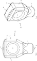
- FIG. 1 shows a perspective side view of an anchoring assembly 1.
- the anchoring assembly 1 comprises a fixing device 2, in which an anchoring element 4 is held by means of a clamping element.
- FIGS 2a and 2b show a perspective view and a side view, respectively, of a fixing device 10.
- the fixing device 10 is an integral element, substantially made of stainless steel, and comprises a weld stud 11, an aluminium ball 12 and a fixing element 13 provided with a through hole 14.
- the fixing element 13 is configured so that the clamping element (not shown in figures 2a and 2b ), such as the clamping element 3 shown in figure 1 , can be engagingly clamped on the fixing element 13 in a simple but firm manner.
- the specific configurations of the sides 15 and the upper side 16 are not relevant as such, as long as a correspondingly designed clamping element is available.
- FIGS 3a, 3b show a perspective view and a front view, respectively, of an alternative example of a fixing device 20.
- the fixing device 20 is substantially made of stainless steel and comprises a sleeve 21 provided with internal screw thread (not shown) and a fixing element 23 provided with a through hole 24, sides 25 and an upper side 26, comparable to the fixing element 13 of figure 2 .
- the fixing device 20 can be fixed as such to a weld stud (not shown in figures 3a, 3b , but forming part of the fixing device) provided with external screw thread, as will be explained in more detail yet with reference to figure 6 .
- Figure 4 is a perspective top plan view of a clamping element 30 comparable to the clamping element 3 of figure 1 .
- the clamping element 30 may be made of plastic material or of a(n) (at least slightly) elastic metal.
- the clamping element 30 comprises a beam-shaped central element 31, which is provided with keyhole-shaped recesses 31 at the short ends thereof. Arms of an anchoring member (not shown in figure 4 ) having a circular cross-section can be accommodated in the circular part 33 of the keyhole-shaped recesses 32.
- the arms (not shown) can be guided to the circular parts 33 via guide surfaces 34 of the keyhole-shaped recesses 32.
- the keyhole-shaped recess 32 is narrowed at the location of the transition between the guide surfaces 34 and the circular parts 33 of the recesses.
- Figure 5 shows a part of a metal object 40 with anchoring elements provided on the metal object 40 during various stages of attachment.
- the metal object 40 may be a stainless steel wall, against which cement must be poured and allowed to cure.
- a fixing device 10 provided with a weld stud 11 is stud-welded to the metal object 40.
- the second fixing device 10b has an anchoring element 4 inserted into the through hole 14 thereof.
- the fixing device 10c has an anchoring element 4 clamped thereon by means of the clamping element 30.
- Figure 6 shows a part of a metal object 50 with anchoring assemblies provided with a fixing device 20 provided thereon during various stages of assembly.
- a weld stud 27a provided with external screw thread 28 is welded to the metal object 50.
- an insulation block 29 is placed over the weld studs 22 in such a manner that the screw thread 28 is clear at all times.
- a ring 19 is placed over the external screw thread 28b of the weld stud 27b.
- a fixing device 20c provided with internal screw thread is placed over external screw thread of the weld stud 27c.
- An anchoring element 4 is inserted into the through hole 24 of the fixing device 20d.
- a clamping element 30 is placed over the anchoring element 4 and the fixing device 20e.
- anchoring assemblies and fixing devices are shown and described in the appended drawings and the above description. It will be understood, however, that many variants, which may be obvious to those skilled in the art, are conceivable within the scope of the present invention, which is defined in the appended claims. Thus, various suitable materials may be used for the various elements.
- welding stud as used herein is understood to mean a pin-shaped element suitable for being welded to a metal object with its short end surface. The separation between a weld stud and the fixing device may be provided at a different position, using different fixing means, than the position and the fixing means shown and described herein.
- Various forms of anchoring elements can be used, of course, depending on the use and/or the user's requirements.
- the various elements may furthermore be connected together in various ways. The essence of the invention is that the fixing device is fixed to a metal object by stud welding.
Landscapes
- Engineering & Computer Science (AREA)
- Architecture (AREA)
- Physics & Mathematics (AREA)
- Electromagnetism (AREA)
- Civil Engineering (AREA)
- Structural Engineering (AREA)
- Joining Of Building Structures In Genera (AREA)
Claims (13)
- Verfahren zum Befestigen einer Verankerungsbaugruppe (1) zum Verankern einer Auskleidung aus einem in flüssiger Form auf ein Metallobjekt aufgebrachten gehärteten Auskleidungsmaterial, wobei das Verfahren die folgenden Schritte umfasst:0) Bereitstellen der Verankerungsbaugruppe (1), wobei die Verankerungsbaugruppe (1) Folgendes umfasst: eine Befestigungsvorrichtung (2, 10, 20), ausgelegt zum Schweißen an ein Metallobjekt (40, 50), wobei die Befestigungsvorrichtung (2, 10, 20) ein Schweißelement und ein mit einem Durchgangsloch (14) versehenes Befestigungselement (13, 23) umfasst, und ein Verankerungselement (4), das durch das Durchgangsloch (14) der Befestigungsvorrichtung (2, 10, 20) geführt werden kann, wobei das Schweißelement einen zum Anschweißen an ein Metallobjekt (40, 50) durch Bolzenschweißen konzipierten Schweißbolzen (11, 21) umfasst;1) Bereitstellen des Metallobjekts (40, 50);2) Verschweißen der Befestigungsvorrichtung (10) mit dem Metallobjekt (40, 50); und3) Verbinden des Verankerungselements (4) mit der Befestigungsvorrichtung (10);
dadurch gekennzeichnet, dass der Schweißbolzen durch Bolzenschweißen in Schritt 2) mit dem Metallobjekt (40, 50) verschweißt ist. - Verfahren nach Anspruch 1, dadurch gekennzeichnet, dass der Schweißbolzen (11, 21) über seine Länge einen im Wesentlichen konstanten Querschnitt aufweist.
- Verfahren nach Anspruch 1 oder 2, dadurch gekennzeichnet, dass die Schweißfläche an dem Ende des Schweißelements fern von dem Befestigungselement (13, 23) vorgesehen ist.
- Verfahren nach Anspruch 3, dadurch gekennzeichnet, dass Aluminium (12) auf der Schweißfläche vorgesehen ist.
- Verfahren nach Anspruch 4, dadurch gekennzeichnet, dass das Aluminium (12) in der Schweißfläche des Schweißbolzens (11) in Form einer Kugel (12) vorliegt.
- Verfahren nach einem oder mehreren der vorherigen Ansprüche, dadurch gekennzeichnet, dass das Befestigungselement (13, 23) wenigstens im Wesentlichen flach ist, wobei das Durchgangsloch (14) von einer ebenen Fläche des Befestigungselements (13, 23) zu einer gegenüberliegenden ebenen Fläche des Befestigungselements (13, 23) verläuft.
- Verfahren nach einem oder mehreren der vorherigen Ansprüche, dadurch gekennzeichnet, dass die Befestigungsvorrichtung (2, 10, 20) ein integrales Element bildet.
- Verfahren nach einem oder mehreren der Ansprüche 1 - 6, dadurch gekennzeichnet, dass die Befestigungsvorrichtung (2, 10, 20) ein zusammengesetztes oder wenigstens zusammensetzbares Element ist.
- Verfahren nach Anspruch 8, dadurch gekennzeichnet, dass die Befestigungsvorrichtung (2, 10, 20) einen Schweißbolzen und ein Befestigungselement (13, 23) umfasst, das damit verbunden oder wenigstens damit zu verbinden ist.
- Verfahren nach Anspruch 9, dadurch gekennzeichnet, dass der Schweißbolzen oder das Befestigungselement (13, 23) ein Außenschraubgewinde und das andere der beiden Elemente ein entsprechendes Innenschraubgewinde umfasst.
- Verfahren nach Anspruch 10, dadurch gekennzeichnet, dass das Befestigungselement (13, 23) aus Edelstahl gefertigt ist.
- Verfahren nach einem oder mehreren der vorherigen Ansprüche, dadurch gekennzeichnet, dass die Verankerungsbaugruppe ein Klemmelement (3, 30) umfasst, mit dem das Verankerungselement an der verwendeten Befestigungsvorrichtung (2, 10, 20) festgeklemmt wird.
- Verfahren nach Anspruch 12, dadurch gekennzeichnet, dass die Befestigungsvorrichtung (2, 10, 20) einen ersten Eingriffsflächenabschnitt und das Klemmelement (3, 30) eine entsprechende zweite Eingriffsfläche umfasst.
Priority Applications (1)
| Application Number | Priority Date | Filing Date | Title |
|---|---|---|---|
| PL12168118T PL2525006T3 (pl) | 2011-05-16 | 2012-05-15 | Zespół kotwiący i urządzenie mocujące do takiego zespołu kotwiącego |
Applications Claiming Priority (1)
| Application Number | Priority Date | Filing Date | Title |
|---|---|---|---|
| NL2006790A NL2006790C2 (nl) | 2011-05-16 | 2011-05-16 | Verankeringssamenstel en bevestigingsorgaan voor een dergelijk verankeringssamenstel. |
Publications (2)
| Publication Number | Publication Date |
|---|---|
| EP2525006A1 EP2525006A1 (de) | 2012-11-21 |
| EP2525006B1 true EP2525006B1 (de) | 2019-08-28 |
Family
ID=46044592
Family Applications (1)
| Application Number | Title | Priority Date | Filing Date |
|---|---|---|---|
| EP12168118.3A Active EP2525006B1 (de) | 2011-05-16 | 2012-05-15 | Verankerungsvorrichtung und Fixiervorrichtung für die Verankerungsanordnung |
Country Status (6)
| Country | Link |
|---|---|
| US (1) | US8844239B2 (de) |
| EP (1) | EP2525006B1 (de) |
| ES (1) | ES2749648T3 (de) |
| NL (1) | NL2006790C2 (de) |
| PL (1) | PL2525006T3 (de) |
| PT (1) | PT2525006T (de) |
Families Citing this family (8)
| Publication number | Priority date | Publication date | Assignee | Title |
|---|---|---|---|---|
| US9347232B1 (en) * | 2014-03-10 | 2016-05-24 | Sidney E. Francies, III | Lifting and leveling assembly for precast concrete slabs and method |
| DE202014005475U1 (de) * | 2014-07-03 | 2015-10-06 | Vhi Vertriebsgesellschaft Für Hochtemperaturwerkstoffe Und Industriebedarf Mbh | Feuerfestauskleidung und eine Befestigungsvorrichtung dafür |
| US10597871B2 (en) | 2016-07-21 | 2020-03-24 | Meadow Burke, Llc | Lifting and leveling insert for a precast concrete slab |
| US10309103B2 (en) | 2016-07-21 | 2019-06-04 | Meadow Burke, Llc | Lifting and leveling insert for a precast concrete slab |
| USD882905S1 (en) | 2018-05-31 | 2020-04-28 | Meadow Burke, Llc | Lift level |
| USD891237S1 (en) * | 2018-11-01 | 2020-07-28 | Refractory Anchors Inc. | Refractory anchor |
| US12044477B2 (en) | 2022-03-16 | 2024-07-23 | Brand Shared Services Llc | Refractory anchors and eye-mounts |
| NL2035391B1 (en) * | 2023-07-14 | 2025-01-28 | Silicon Holding B V | Anchor system for refractory linings |
Citations (1)
| Publication number | Priority date | Publication date | Assignee | Title |
|---|---|---|---|---|
| DE20303935U1 (de) * | 2003-03-12 | 2003-05-22 | Refratechnik Holding GmbH, 85737 Ismaning | Mehrteilige Ankereinrichtung für eine feuerfeste Zustellung |
Family Cites Families (18)
| Publication number | Priority date | Publication date | Assignee | Title |
|---|---|---|---|---|
| US2724165A (en) * | 1955-11-22 | williams | ||
| US2520998A (en) * | 1947-05-20 | 1950-09-05 | William J Cella | Reinforcing means for bottle containing crates |
| FR2054723A5 (de) * | 1969-07-24 | 1971-05-07 | Loire Atel Forges | |
| US3657851A (en) * | 1970-06-24 | 1972-04-25 | Trw Inc | Two-piece refractory anchor for heavy duty construction |
| DE7606293U1 (de) * | 1976-03-02 | 1977-08-25 | Fa. Wilhelm Modersohn Gmbh & Co Kg, 4905 Spenge | Ankerschiene, anschweissplatte o.dgl. mit einem angeschweissten verankerungsstueck |
| DE3017840C2 (de) * | 1980-05-09 | 1984-05-17 | Kaiser-Omnia Bausysteme Gmbh & Co, 6000 Frankfurt | Bleibende Schalung für eine Betondecke und Anker hierfür |
| US4835933A (en) * | 1988-02-11 | 1989-06-06 | Yung Fernand P | Rebar spacer assembly |
| US5493833A (en) * | 1992-05-06 | 1996-02-27 | Trw Inc. | Welding stud and method of forming same |
| US5358423A (en) * | 1993-11-24 | 1994-10-25 | Minnesota Mining And Manufacturing Company | Connecting clip |
| IT1284894B1 (it) * | 1996-09-30 | 1998-05-28 | Sergio Zambelli | Dispositivo per il sollevamento di manufatti prefabbricati in particolare in calcestruzzo o simili |
| US6058672A (en) * | 1998-06-03 | 2000-05-09 | Mcclellan; Robert B. | Construction of wall panel and panel structure |
| KR100528288B1 (ko) * | 2003-04-28 | 2005-11-15 | 한국정밀공업(주) | 웰딩 스터드의 알루미늄 볼 압입장치 |
| US7065925B2 (en) * | 2004-02-11 | 2006-06-27 | Universal Form Clamp Of Chicago, Inc. | Concrete anchor |
| WO2006017411A1 (en) * | 2004-08-02 | 2006-02-16 | Minor Jack M | Concrete reinforcing bar clip |
| US7282662B2 (en) * | 2005-12-12 | 2007-10-16 | Nelson Stud Welding, Inc. | Paint groove stud |
| AU2007202357B8 (en) * | 2006-06-28 | 2013-12-19 | Illinois Tool Works Inc. | Cast-in lifting anchor |
| US20080196324A1 (en) * | 2007-02-21 | 2008-08-21 | Woodstock Percussion Pty Ltd | Concrete Lifting Anchor |
| KR100995121B1 (ko) * | 2010-05-19 | 2010-11-18 | 류승일 | 파스너 고정을 위한 개량된 매입형 채널의 제조방법 |
-
2011
- 2011-05-16 NL NL2006790A patent/NL2006790C2/nl not_active IP Right Cessation
-
2012
- 2012-05-15 PT PT121681183T patent/PT2525006T/pt unknown
- 2012-05-15 EP EP12168118.3A patent/EP2525006B1/de active Active
- 2012-05-15 US US13/471,909 patent/US8844239B2/en active Active
- 2012-05-15 ES ES12168118T patent/ES2749648T3/es active Active
- 2012-05-15 PL PL12168118T patent/PL2525006T3/pl unknown
Patent Citations (1)
| Publication number | Priority date | Publication date | Assignee | Title |
|---|---|---|---|---|
| DE20303935U1 (de) * | 2003-03-12 | 2003-05-22 | Refratechnik Holding GmbH, 85737 Ismaning | Mehrteilige Ankereinrichtung für eine feuerfeste Zustellung |
Non-Patent Citations (2)
| Title |
|---|
| "Production fastening systems - general information", 31 October 2007 (2007-10-31), XP055237669, Retrieved from the Internet <URL:http://www.pfsno.com/wp-content/uploads/pfs-metal-fastener-catalog.pdf> [retrieved on 20151218] * |
| "Recommended Practices for Stud Welding", ANSI/AWS C5.4-84 AN: AMERICAN NATIONAL STANDARD INSTITUTE,, 29 July 1982 (1982-07-29), XP001341808 * |
Also Published As
| Publication number | Publication date |
|---|---|
| EP2525006A1 (de) | 2012-11-21 |
| US8844239B2 (en) | 2014-09-30 |
| NL2006790C2 (nl) | 2012-11-19 |
| ES2749648T3 (es) | 2020-03-23 |
| PT2525006T (pt) | 2019-10-25 |
| US20120291393A1 (en) | 2012-11-22 |
| PL2525006T3 (pl) | 2020-01-31 |
Similar Documents
| Publication | Publication Date | Title |
|---|---|---|
| EP2525006B1 (de) | Verankerungsvorrichtung und Fixiervorrichtung für die Verankerungsanordnung | |
| US12037789B2 (en) | Anchoring assembly for anchoring a liner of a cured lining material, a ferrule suitable for use with the anchoring assembly, an anchoring mounting assembly further comprising a ferrule holder and the use of the anchoring assembly | |
| US9580922B2 (en) | Locking device having wall formwork locking device and process | |
| US10024051B2 (en) | Embedded concrete anchor system | |
| KR101530944B1 (ko) | 앙카볼트용 인서트구조체 | |
| JPWO2019064404A1 (ja) | 鉄筋用スペーサ | |
| KR101788510B1 (ko) | 고정력이 향상된 단열재용 인서트 | |
| EP1067248A2 (de) | Verankerungsvorrichtung für Betonbauteile oder ähnliches mit einem einfach zu benutzendem Element zum Verankern an dem Bauteil | |
| WO2015054727A1 (en) | Hole repair | |
| KR101463484B1 (ko) | 스페이서 조립체를 구비한 탈형 데크 | |
| CN106013619B (zh) | 一种可调钢筋角度的对接装置 | |
| KR20140073288A (ko) | 보/기둥 체결장치 및 이를 이용한 보/기둥의 조립 방법 | |
| JP2014145154A (ja) | 後施工曲折アンカーボルトとその施工方法 | |
| JP2008280840A (ja) | コンクリート天端スペーサー | |
| KR200316260Y1 (ko) | 핸드레일과 중간 지지봉의 비용접식 결합구조 | |
| AU781708B2 (en) | Connecting ferrule | |
| JP3218618U (ja) | 陸上競技場トラックの内圏縁石装置 | |
| KR102183626B1 (ko) | 지지력을 상승시킨 건축용 앵커 어셈블리 | |
| KR200373289Y1 (ko) | 거푸집 간격유지구 | |
| JP5876796B2 (ja) | 目地形成部材の固定治具 | |
| JP2007032055A (ja) | コンクリート成形体のボイドユニット | |
| JP2017036605A (ja) | 棒状部材の連結金具 | |
| EP2189595A1 (de) | Montagevorrichtung für Schutzgeländer | |
| JP3190056U (ja) | 鉄骨柱脚ラーメン構造における鉄骨柱脚固定構造 | |
| RU151096U1 (ru) | Магнитное удерживающее устройство |
Legal Events
| Date | Code | Title | Description |
|---|---|---|---|
| PUAI | Public reference made under article 153(3) epc to a published international application that has entered the european phase |
Free format text: ORIGINAL CODE: 0009012 |
|
| AK | Designated contracting states |
Kind code of ref document: A1 Designated state(s): AL AT BE BG CH CY CZ DE DK EE ES FI FR GB GR HR HU IE IS IT LI LT LU LV MC MK MT NL NO PL PT RO RS SE SI SK SM TR |
|
| AX | Request for extension of the european patent |
Extension state: BA ME |
|
| 17P | Request for examination filed |
Effective date: 20130521 |
|
| 17Q | First examination report despatched |
Effective date: 20150205 |
|
| STAA | Information on the status of an ep patent application or granted ep patent |
Free format text: STATUS: EXAMINATION IS IN PROGRESS |
|
| GRAP | Despatch of communication of intention to grant a patent |
Free format text: ORIGINAL CODE: EPIDOSNIGR1 |
|
| STAA | Information on the status of an ep patent application or granted ep patent |
Free format text: STATUS: GRANT OF PATENT IS INTENDED |
|
| INTG | Intention to grant announced |
Effective date: 20190401 |
|
| GRAS | Grant fee paid |
Free format text: ORIGINAL CODE: EPIDOSNIGR3 |
|
| GRAA | (expected) grant |
Free format text: ORIGINAL CODE: 0009210 |
|
| STAA | Information on the status of an ep patent application or granted ep patent |
Free format text: STATUS: THE PATENT HAS BEEN GRANTED |
|
| RAP1 | Party data changed (applicant data changed or rights of an application transferred) |
Owner name: SILICON HOLDING B.V. |
|
| RIN1 | Information on inventor provided before grant (corrected) |
Inventor name: GAROT, WOUTER |
|
| AK | Designated contracting states |
Kind code of ref document: B1 Designated state(s): AL AT BE BG CH CY CZ DE DK EE ES FI FR GB GR HR HU IE IS IT LI LT LU LV MC MK MT NL NO PL PT RO RS SE SI SK SM TR |
|
| REG | Reference to a national code |
Ref country code: GB Ref legal event code: FG4D |
|
| REG | Reference to a national code |
Ref country code: CH Ref legal event code: EP |
|
| REG | Reference to a national code |
Ref country code: AT Ref legal event code: REF Ref document number: 1172586 Country of ref document: AT Kind code of ref document: T Effective date: 20190915 |
|
| REG | Reference to a national code |
Ref country code: IE Ref legal event code: FG4D |
|
| REG | Reference to a national code |
Ref country code: DE Ref legal event code: R096 Ref document number: 602012063312 Country of ref document: DE |
|
| REG | Reference to a national code |
Ref country code: NL Ref legal event code: FP |
|
| REG | Reference to a national code |
Ref country code: SE Ref legal event code: TRGR |
|
| REG | Reference to a national code |
Ref country code: PT Ref legal event code: SC4A Ref document number: 2525006 Country of ref document: PT Date of ref document: 20191025 Kind code of ref document: T Free format text: AVAILABILITY OF NATIONAL TRANSLATION Effective date: 20191008 |
|
| REG | Reference to a national code |
Ref country code: CH Ref legal event code: NV Representative=s name: CABINET GERMAIN AND MAUREAU, CH |
|
| REG | Reference to a national code |
Ref country code: LT Ref legal event code: MG4D |
|
| PG25 | Lapsed in a contracting state [announced via postgrant information from national office to epo] |
Ref country code: FI Free format text: LAPSE BECAUSE OF FAILURE TO SUBMIT A TRANSLATION OF THE DESCRIPTION OR TO PAY THE FEE WITHIN THE PRESCRIBED TIME-LIMIT Effective date: 20190828 Ref country code: NO Free format text: LAPSE BECAUSE OF FAILURE TO SUBMIT A TRANSLATION OF THE DESCRIPTION OR TO PAY THE FEE WITHIN THE PRESCRIBED TIME-LIMIT Effective date: 20191128 Ref country code: BG Free format text: LAPSE BECAUSE OF FAILURE TO SUBMIT A TRANSLATION OF THE DESCRIPTION OR TO PAY THE FEE WITHIN THE PRESCRIBED TIME-LIMIT Effective date: 20191128 Ref country code: LT Free format text: LAPSE BECAUSE OF FAILURE TO SUBMIT A TRANSLATION OF THE DESCRIPTION OR TO PAY THE FEE WITHIN THE PRESCRIBED TIME-LIMIT Effective date: 20190828 Ref country code: HR Free format text: LAPSE BECAUSE OF FAILURE TO SUBMIT A TRANSLATION OF THE DESCRIPTION OR TO PAY THE FEE WITHIN THE PRESCRIBED TIME-LIMIT Effective date: 20190828 |
|
| PG25 | Lapsed in a contracting state [announced via postgrant information from national office to epo] |
Ref country code: RS Free format text: LAPSE BECAUSE OF FAILURE TO SUBMIT A TRANSLATION OF THE DESCRIPTION OR TO PAY THE FEE WITHIN THE PRESCRIBED TIME-LIMIT Effective date: 20190828 Ref country code: AL Free format text: LAPSE BECAUSE OF FAILURE TO SUBMIT A TRANSLATION OF THE DESCRIPTION OR TO PAY THE FEE WITHIN THE PRESCRIBED TIME-LIMIT Effective date: 20190828 Ref country code: GR Free format text: LAPSE BECAUSE OF FAILURE TO SUBMIT A TRANSLATION OF THE DESCRIPTION OR TO PAY THE FEE WITHIN THE PRESCRIBED TIME-LIMIT Effective date: 20191129 Ref country code: LV Free format text: LAPSE BECAUSE OF FAILURE TO SUBMIT A TRANSLATION OF THE DESCRIPTION OR TO PAY THE FEE WITHIN THE PRESCRIBED TIME-LIMIT Effective date: 20190828 Ref country code: IS Free format text: LAPSE BECAUSE OF FAILURE TO SUBMIT A TRANSLATION OF THE DESCRIPTION OR TO PAY THE FEE WITHIN THE PRESCRIBED TIME-LIMIT Effective date: 20191228 |
|
| REG | Reference to a national code |
Ref country code: ES Ref legal event code: FG2A Ref document number: 2749648 Country of ref document: ES Kind code of ref document: T3 Effective date: 20200323 |
|
| PG25 | Lapsed in a contracting state [announced via postgrant information from national office to epo] |
Ref country code: DK Free format text: LAPSE BECAUSE OF FAILURE TO SUBMIT A TRANSLATION OF THE DESCRIPTION OR TO PAY THE FEE WITHIN THE PRESCRIBED TIME-LIMIT Effective date: 20190828 Ref country code: EE Free format text: LAPSE BECAUSE OF FAILURE TO SUBMIT A TRANSLATION OF THE DESCRIPTION OR TO PAY THE FEE WITHIN THE PRESCRIBED TIME-LIMIT Effective date: 20190828 Ref country code: RO Free format text: LAPSE BECAUSE OF FAILURE TO SUBMIT A TRANSLATION OF THE DESCRIPTION OR TO PAY THE FEE WITHIN THE PRESCRIBED TIME-LIMIT Effective date: 20190828 |
|
| PG25 | Lapsed in a contracting state [announced via postgrant information from national office to epo] |
Ref country code: SK Free format text: LAPSE BECAUSE OF FAILURE TO SUBMIT A TRANSLATION OF THE DESCRIPTION OR TO PAY THE FEE WITHIN THE PRESCRIBED TIME-LIMIT Effective date: 20190828 Ref country code: CZ Free format text: LAPSE BECAUSE OF FAILURE TO SUBMIT A TRANSLATION OF THE DESCRIPTION OR TO PAY THE FEE WITHIN THE PRESCRIBED TIME-LIMIT Effective date: 20190828 Ref country code: SM Free format text: LAPSE BECAUSE OF FAILURE TO SUBMIT A TRANSLATION OF THE DESCRIPTION OR TO PAY THE FEE WITHIN THE PRESCRIBED TIME-LIMIT Effective date: 20190828 Ref country code: IS Free format text: LAPSE BECAUSE OF FAILURE TO SUBMIT A TRANSLATION OF THE DESCRIPTION OR TO PAY THE FEE WITHIN THE PRESCRIBED TIME-LIMIT Effective date: 20200224 |
|
| REG | Reference to a national code |
Ref country code: DE Ref legal event code: R097 Ref document number: 602012063312 Country of ref document: DE |
|
| PLBE | No opposition filed within time limit |
Free format text: ORIGINAL CODE: 0009261 |
|
| STAA | Information on the status of an ep patent application or granted ep patent |
Free format text: STATUS: NO OPPOSITION FILED WITHIN TIME LIMIT |
|
| PG2D | Information on lapse in contracting state deleted |
Ref country code: IS |
|
| 26N | No opposition filed |
Effective date: 20200603 |
|
| PG25 | Lapsed in a contracting state [announced via postgrant information from national office to epo] |
Ref country code: SI Free format text: LAPSE BECAUSE OF FAILURE TO SUBMIT A TRANSLATION OF THE DESCRIPTION OR TO PAY THE FEE WITHIN THE PRESCRIBED TIME-LIMIT Effective date: 20190828 |
|
| REG | Reference to a national code |
Ref country code: AT Ref legal event code: UEP Ref document number: 1172586 Country of ref document: AT Kind code of ref document: T Effective date: 20190828 |
|
| PG25 | Lapsed in a contracting state [announced via postgrant information from national office to epo] |
Ref country code: MC Free format text: LAPSE BECAUSE OF FAILURE TO SUBMIT A TRANSLATION OF THE DESCRIPTION OR TO PAY THE FEE WITHIN THE PRESCRIBED TIME-LIMIT Effective date: 20190828 |
|
| PG25 | Lapsed in a contracting state [announced via postgrant information from national office to epo] |
Ref country code: LU Free format text: LAPSE BECAUSE OF NON-PAYMENT OF DUE FEES Effective date: 20200515 |
|
| PG25 | Lapsed in a contracting state [announced via postgrant information from national office to epo] |
Ref country code: MT Free format text: LAPSE BECAUSE OF FAILURE TO SUBMIT A TRANSLATION OF THE DESCRIPTION OR TO PAY THE FEE WITHIN THE PRESCRIBED TIME-LIMIT Effective date: 20190828 Ref country code: CY Free format text: LAPSE BECAUSE OF FAILURE TO SUBMIT A TRANSLATION OF THE DESCRIPTION OR TO PAY THE FEE WITHIN THE PRESCRIBED TIME-LIMIT Effective date: 20190828 |
|
| PG25 | Lapsed in a contracting state [announced via postgrant information from national office to epo] |
Ref country code: MK Free format text: LAPSE BECAUSE OF FAILURE TO SUBMIT A TRANSLATION OF THE DESCRIPTION OR TO PAY THE FEE WITHIN THE PRESCRIBED TIME-LIMIT Effective date: 20190828 |
|
| P01 | Opt-out of the competence of the unified patent court (upc) registered |
Effective date: 20230527 |
|
| PGFP | Annual fee paid to national office [announced via postgrant information from national office to epo] |
Ref country code: NL Payment date: 20250521 Year of fee payment: 14 |
|
| PGFP | Annual fee paid to national office [announced via postgrant information from national office to epo] |
Ref country code: PL Payment date: 20250423 Year of fee payment: 14 Ref country code: DE Payment date: 20250521 Year of fee payment: 14 |
|
| PGFP | Annual fee paid to national office [announced via postgrant information from national office to epo] |
Ref country code: ES Payment date: 20250627 Year of fee payment: 14 |
|
| PGFP | Annual fee paid to national office [announced via postgrant information from national office to epo] |
Ref country code: BE Payment date: 20250521 Year of fee payment: 14 Ref country code: IT Payment date: 20250527 Year of fee payment: 14 |
|
| PGFP | Annual fee paid to national office [announced via postgrant information from national office to epo] |
Ref country code: PT Payment date: 20250502 Year of fee payment: 14 |
|
| PGFP | Annual fee paid to national office [announced via postgrant information from national office to epo] |
Ref country code: FR Payment date: 20250528 Year of fee payment: 14 |
|
| PGFP | Annual fee paid to national office [announced via postgrant information from national office to epo] |
Ref country code: CH Payment date: 20250601 Year of fee payment: 14 |
|
| PGFP | Annual fee paid to national office [announced via postgrant information from national office to epo] |
Ref country code: AT Payment date: 20250522 Year of fee payment: 14 |
|
| PGFP | Annual fee paid to national office [announced via postgrant information from national office to epo] |
Ref country code: TR Payment date: 20250506 Year of fee payment: 14 |
|
| PGFP | Annual fee paid to national office [announced via postgrant information from national office to epo] |
Ref country code: IE Payment date: 20250521 Year of fee payment: 14 |
|
| PGFP | Annual fee paid to national office [announced via postgrant information from national office to epo] |
Ref country code: SE Payment date: 20250521 Year of fee payment: 14 |
|
| PGFP | Annual fee paid to national office [announced via postgrant information from national office to epo] |
Ref country code: GB Payment date: 20260306 Year of fee payment: 15 |