EP2524113B1 - Structure orientable du type endoscope - Google Patents
Structure orientable du type endoscope Download PDFInfo
- Publication number
- EP2524113B1 EP2524113B1 EP11705014.6A EP11705014A EP2524113B1 EP 2524113 B1 EP2524113 B1 EP 2524113B1 EP 11705014 A EP11705014 A EP 11705014A EP 2524113 B1 EP2524113 B1 EP 2524113B1
- Authority
- EP
- European Patent Office
- Prior art keywords
- longitudinal body
- actuator
- structure according
- distal end
- flexible
- Prior art date
- Legal status (The legal status is an assumption and is not a legal conclusion. Google has not performed a legal analysis and makes no representation as to the accuracy of the status listed.)
- Active
Links
Images

Classifications
-
- F—MECHANICAL ENGINEERING; LIGHTING; HEATING; WEAPONS; BLASTING
- F01—MACHINES OR ENGINES IN GENERAL; ENGINE PLANTS IN GENERAL; STEAM ENGINES
- F01D—NON-POSITIVE DISPLACEMENT MACHINES OR ENGINES, e.g. STEAM TURBINES
- F01D21/00—Shutting-down of machines or engines, e.g. in emergency; Regulating, controlling, or safety means not otherwise provided for
- F01D21/003—Arrangements for testing or measuring
-
- G—PHYSICS
- G01—MEASURING; TESTING
- G01N—INVESTIGATING OR ANALYSING MATERIALS BY DETERMINING THEIR CHEMICAL OR PHYSICAL PROPERTIES
- G01N29/00—Investigating or analysing materials by the use of ultrasonic, sonic or infrasonic waves; Visualisation of the interior of objects by transmitting ultrasonic or sonic waves through the object
- G01N29/22—Details, e.g. general constructional or apparatus details
- G01N29/225—Supports, positioning or alignment in moving situation
-
- F—MECHANICAL ENGINEERING; LIGHTING; HEATING; WEAPONS; BLASTING
- F05—INDEXING SCHEMES RELATING TO ENGINES OR PUMPS IN VARIOUS SUBCLASSES OF CLASSES F01-F04
- F05D—INDEXING SCHEME FOR ASPECTS RELATING TO NON-POSITIVE-DISPLACEMENT MACHINES OR ENGINES, GAS-TURBINES OR JET-PROPULSION PLANTS
- F05D2260/00—Function
- F05D2260/80—Diagnostics
-
- Y—GENERAL TAGGING OF NEW TECHNOLOGICAL DEVELOPMENTS; GENERAL TAGGING OF CROSS-SECTIONAL TECHNOLOGIES SPANNING OVER SEVERAL SECTIONS OF THE IPC; TECHNICAL SUBJECTS COVERED BY FORMER USPC CROSS-REFERENCE ART COLLECTIONS [XRACs] AND DIGESTS
- Y10—TECHNICAL SUBJECTS COVERED BY FORMER USPC
- Y10T—TECHNICAL SUBJECTS COVERED BY FORMER US CLASSIFICATION
- Y10T74/00—Machine element or mechanism
- Y10T74/20—Control lever and linkage systems
- Y10T74/20207—Multiple controlling elements for single controlled element
- Y10T74/20305—Robotic arm
-
- Y—GENERAL TAGGING OF NEW TECHNOLOGICAL DEVELOPMENTS; GENERAL TAGGING OF CROSS-SECTIONAL TECHNOLOGIES SPANNING OVER SEVERAL SECTIONS OF THE IPC; TECHNICAL SUBJECTS COVERED BY FORMER USPC CROSS-REFERENCE ART COLLECTIONS [XRACs] AND DIGESTS
- Y10—TECHNICAL SUBJECTS COVERED BY FORMER USPC
- Y10T—TECHNICAL SUBJECTS COVERED BY FORMER US CLASSIFICATION
- Y10T74/00—Machine element or mechanism
- Y10T74/20—Control lever and linkage systems
- Y10T74/20207—Multiple controlling elements for single controlled element
- Y10T74/20305—Robotic arm
- Y10T74/20323—Robotic arm including flaccid drive element
Definitions
- the present invention relates to a flexible and steerable structure for the internal inspection of a mechanical system, such as for example a turbomachine, by means in particular of a type of eddy current sensor or ultrasound.
- Some current flexible and orientable structures such as an endoscope or a non-destructive control probe support, are in the form of long rigid or elastically deformable tubes having an end orientable relative to their longitudinal axis to choose an angle of positioning and facilitate the progression of the endoscope or the probe support.
- actuators such as traction wires or wires of shape memory material. These actuators have their length reduced by traction or under the effect of an increase in temperature, which induces a change in the curvature of the endoscope in the areas where the actuators are located.
- this type of device suffers from limitations mainly due to the lack of mobility and maneuverability in geometrically complex or cramped spaces. Moreover, it also has limitations in terms of curvature capacity of the end of the endoscope.
- the invention aims in particular to provide a simple, economical and effective solution to these problems, to avoid the disadvantages of the known technique.
- a flexible and orientable non-destructive control structure comprising a longitudinal body and at least one actuator making it possible to modify the curvature of at least a portion of the longitudinal body, characterized in that the actuator is carried by a support associated with the longitudinal body and a distal portion of which is spaced apart or separable from the longitudinal body and is connected to a portion of the longitudinal body by a pull wire.
- the invention proposes not to arrange the actuator along the longitudinal body but to mount it on a support spaced from it.
- the support forms a lever arm facilitating the bending of the longitudinal body which is effected by means of a force exerted laterally with respect to the longitudinal body and along the traction wire and no longer along the longitudinal body which allows to amplify the sagging of the longitudinal body.
- the transmission ratio i.e., the ratio of the deflection angle to the length reduction of the actuator, is smaller than that of the prior art. This allows a much more precise positioning of the flexed part of the longitudinal body.
- the force resulting from the control of the actuator is better transmitted to the longitudinal body.
- This good transmission of effort allows the realization of a stable attachment of the flexible structure by deflection and support of a portion of the longitudinal body on a fixed part of a three-dimensional structure to explore. It is thus possible to ensure that a non-destructive control sensor positioned at the distal end of the longitudinal body will be in a static position to perform a non-destructive inspection operation.
- the invention thus makes it possible to explore areas of a turbomachine that were not accessible without dismantling the turbomachine, which contributes to reducing downtimes and costs.
- the actuator is of shape memory material.
- the actuator may be mechanical and include a cable directly connected to the pull wire of the longitudinal body and extending along the distal portion of the support.
- the distal portion of the support may be rigid and in this case the actuator may be a cable as described above.
- the distal portion of the support may be deformable and in this case the actuator may comprise a shape memory material whose contraction controls the deformation of the distal portion of the support and induces traction on the connecting wire to the longitudinal body .
- the traction wire of the longitudinal body is connected to the latter at a distance from its distal end in an area intended to come in point or quasi-point support on a fixed element of a structure to inspect to form a pivot point.
- This pivot point is located between the distal end of the longitudinal body and the point of connection of the pull wire to the longitudinal body. In this way, it is possible to perform angular scanning with the distal end of the longitudinal body, which can be useful when it is desired to continuously display a certain angular extent of the interior of the structure to be inspected.
- the pulling wire is connected to the distal end of the longitudinal body or in the vicinity of this distal end.
- the non-destructive control means mounted at the distal end of the longitudinal body are, for example, eddy current probes or ultrasonic probes.
- the pull wire is metallic.
- the longitudinal body may also comprise at least one portion equipped with at least one actuator, of the mechanical or shape-memory type to achieve additional sagging of the longitudinal body.
- FIG. 1 represents a flexible and orientable non-destructive testing structure of the prior art, comprising a longitudinal body 12 equipped with an actuator 14 of shape memory material disposed along the longitudinal body 12 and inside thereof .
- This actuator 14 is for example in the form of a wire connected to power supply means for heating by Joule effect of the wire. The heating of the wire 14 induces a contraction thereof, which leads to a sagging of the longitudinal body 12.
- the figure 2 represents a steerable and flexible structure similar to that of the figure 1 , with the difference that the actuator is a wire 16 extending along the longitudinal body 12 to the distal end of the longitudinal body 12.
- the wire 16 is held along the longitudinal body 12 by means of a plurality of hollow guides 18 fixed to the longitudinal body 12. With this type of control structure, a pull (arrow A) applied to the proximal end of the wire 16 leads to a deflection of the distal end of the longitudinal body 12.
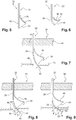
- the invention proposes to associate with the flexible and orientable structure a support 22, a distal portion 24 of which is remote or devoid of the longitudinal body 26 and carries an actuator 28, this distal portion 24 being connected to the longitudinal body 26 by a thread of traction 30.
- the distal portion 24 is rigid.
- the actuator 28 is a cable that extends along the support 22 in hollow guides 18 fixed to the support 22.
- the actuator 28 is directly connected at the end of the distal portion 24 of the support 22 to the wire 30.
- traction device connected to the distal end of the longitudinal body 26.
- a traction (arrow B) applied to the proximal end of the cable 28 induces a deflection of the distal end of the longitudinal body 26, the support 22 remaining fixed during this operation ( figure 4 ).
- the flexible and steerable structure 32 comprises an actuator 34 in the form of a shape memory material wire integrated in the distal portion 36 of the support 22 which is deformable.
- the distal portion 36 is connected to the longitudinal body 26 by a pull wire 30.
- the heating of the wire of shape memory material leads to a contraction of the latter inducing a bending of the distal portion 36 of the support 22 causing a sagging of the longitudinal body 26 ( figure 6 ).
- the longitudinal body 26 may be of elastically deformable material, which allows its return to the rest position ( figures 3 and 5 ) when the pulling cable 28 is released or when the heating of the wire 34 of shape memory material is stopped.
- the distal portion 24, 36 of the support 22 constitutes a lever arm for the deflection of the longitudinal body 26, allowing precise positioning of the bent portion of the longitudinal body 26 due to a transmission ratio (bending angle over a length of reduction actuator) smaller than in the prior art.
- a transmission ratio bending angle over a length of reduction actuator
- the figure 7 is an axial section of a structure to be inspected 38 having two walls 40, 42 spaced from one another and having two openings 44, 46 for passing a flexible and steerable structure according to the invention.
- the pull wire 30 is connected to the distal end of the longitudinal body 26.
- the longitudinal body 26 is inserted into the two openings 44, 46 and the support 22 is inserted into the first opening so as to its distal portion 48 is located between the two walls 40, 42.
- the control of the actuator of the distal portion 48 induces a flexion of the longitudinal body 26 and causes the distal end 50 of the longitudinal body 26 to rest on the edge of the second opening.
- a portion of the traction wire 30 in the immediate vicinity of the longitudinal body is pressed against the inner surface of the second opening 46 during the deflection of the longitudinal body 26.
- the figure 8 represents a structure to be inspected 38 similar to that of the figure 7 .
- the pulling wire 30 is connected to the longitudinal body 26 at a distance d from its distal end 54.
- the longitudinal body 26 is inserted inside the second opening 46 so that, during the deflection, its part of end 52 comes in one-off or near-point support on one edge (or edge) of the second opening ( figure 8 ).
- This configuration allows the formation of a pivot point 53 between the distal end 54 of the longitudinal body 26 and the connection point 56 of the traction wire 30 to the longitudinal body 26.
- the repeated control of the actuator carried by the distal portion 48 of the support 22 allows an angular sweep with the distal end of the longitudinal body 26.
- the actuator for performing the angular sweep may be the same actuator as that used for the initial deflection ( figure 8 ) of the longitudinal body in the case of a mechanical actuator such as a cable, the continuation of the traction inducing a pivoting of the distal end of the longitudinal body 26.
- a mechanical actuator such as a cable
- a second wire also of shape memory material can be integrated with the distal portion 48 of the support 22, and the repetitive actuation of this second wire makes it possible to perform the angular scanning of the distal end 54 of the longitudinal body 26.
- the mounting of a flexible and steerable structure 20, 32 in a mechanical structure of the type of Figures 7 and 8 is achieved by firstly inserting the unstretched longitudinal body 26 through the first and second openings 44, 46.
- the carrier 22 is also inserted through the first opening 44 by pivoting and then translating and the pulling wire 30 is then put in tension to place the structure 20, 32 in the waiting position as on the figures 3 and 5 .
- Non-destructive control means may be mounted at the distal end of the longitudinal body 26. These means are, for example, eddy current probes or ultrasonic probes.
- the flexible structure 20, 32 comprises at least one mechanical actuator 16 or shape memory 14 integrated in the longitudinal body 26.
Landscapes
- Engineering & Computer Science (AREA)
- Biochemistry (AREA)
- Immunology (AREA)
- Physics & Mathematics (AREA)
- Health & Medical Sciences (AREA)
- Life Sciences & Earth Sciences (AREA)
- Chemical & Material Sciences (AREA)
- Analytical Chemistry (AREA)
- Mechanical Engineering (AREA)
- General Engineering & Computer Science (AREA)
- General Health & Medical Sciences (AREA)
- General Physics & Mathematics (AREA)
- Pathology (AREA)
- Investigating Or Analyzing Materials By The Use Of Magnetic Means (AREA)
- Instruments For Viewing The Inside Of Hollow Bodies (AREA)
- Endoscopes (AREA)
- Investigating Or Analyzing Materials By The Use Of Ultrasonic Waves (AREA)
- Control Of Position Or Direction (AREA)
- Ultra Sonic Daignosis Equipment (AREA)
Description
- La présente invention concerne une structure flexible et orientable destinée à l'inspection interne d'un système mécanique, tel que par exemple une turbomachine, au moyen notamment d'un capteur du type à courants de Foucault ou à ultrasons.
- Certaines structures flexibles et orientables actuelles telles qu'un endoscope ou un support d'une sonde de contrôle non destructif, se présentent sous la forme de longs tubes rigides ou élastiquement déformables ayant une extrémité orientable par rapport à leur axe longitudinal pour choisir un angle de positionnement particulier et faciliter la progression de l'endoscope ou du support de la sonde.
- Afin de courber de manière adéquate une zone particulière de l'endoscope, on a déjà proposé de disposer le long de sa structure des actionneurs mécaniques tels que des fils de traction ou bien des fils en matériau à mémoire de forme. Ces actionneurs voient leur longueur réduite par traction ou bien sous l'effet d'une augmentation de la température, ce qui induit une modification de la courbure de l'endoscope dans les zones où sont localisés les actionneurs.
- Toutefois, ce type de dispositif souffre de limitations dues principalement au manque de mobilité et de manoeuvrabilité dans des espaces géométriquement complexes ou exigus. Par ailleurs, il présente également des limitations en terme de capacité de courbure de l'extrémité de l'endoscope.
- Afin de résoudre cette difficulté, la demanderesse a proposé dans sa demande
FR 07/06726 - Toutefois, les courbures que l'on peut obtenir avec ce type de dispositif ainsi qu'avec ceux mentionnés précédemment restent limitées, ce qui restreint leurs possibilités d'utilisation.
- De plus, dans certaines situations d'inspection d'une turbomachine, il peut être souhaitable de réaliser un accrochage stable et fiable du dispositif sur des parties fixes de la turbomachine dans le but d'effectuer un contrôle non destructif et/ou de limiter l'effet de la gravité sur l'ensemble du dispositif et poursuivre l'inspection de la turbomachine.
- L'invention a notamment pour but d'apporter une solution simple, économique et efficace à ces problèmes, permettant d'éviter les inconvénients de la technique connue.
- A cette fin, elle propose une structure flexible et orientable de contrôle non destructif, comprenant un corps longitudinal et au moins un actionneur permettant de modifier la courbure d'au moins une partie du corps longitudinal, caractérisée en ce que l'actionneur est porté par un support associé au corps longitudinal et dont une partie distale est écartée ou écartable du corps longitudinal et est reliée à une partie du corps longitudinal par un fil de traction.
- A la différence de la technique antérieure, l'invention propose non plus d'agencer l'actionneur le long du corps longitudinal mais de le monter sur un support écarté de celui-ci.
- Dans cette configuration, le support forme un bras de levier facilitant le fléchissement du corps longitudinal lequel s'effectue au moyen d'une force exercée latéralement par rapport au corps longitudinal et suivant le fil de traction et non plus le long du corps longitudinal ce qui permet d'amplifier le fléchissement du corps longitudinal.
- Le rapport de transmission, c'est-à-dire le rapport entre l'angle de fléchissement et la réduction de longueur de l'actionneur, est plus petit que celui de l'art antérieur. Cela permet d'avoir un positionnement beaucoup plus précis de la partie fléchie du corps longitudinal.
- L'effort résultant de la commande de l'actionneur est mieux transmis au corps longitudinal. Cette bonne transmission de l'effort autorise la réalisation d'un accrochage stable de la structure flexible par fléchissement et appui d'une partie du corps longitudinal sur une partie fixe d'une structure tridimensionnelle à explorer. Il est ainsi possible de garantir qu'un capteur de contrôle non destructif positionné à l'extrémité distale du corps longitudinal sera en position statique pour réaliser une opération de contrôle non destructif.
- Dans l'industrie aéronautique, l'invention rend ainsi possible l'exploration de zones d'une turbomachine qui n'étaient pas accessibles sans démontage de la turbomachine, ce qui contribue à réduire les temps d'immobilisation et les coûts.
- Selon une autre caractéristique de l'invention, l'actionneur est en matériau à mémoire de forme.
- En variante, l'actionneur peut être mécanique et comprendre un câble relié directement au fil de traction du corps longitudinal et qui s'étend le long de la partie distale du support.
- La partie distale du support peut être rigide et dans ce cas l'actionneur peut être un câble tel que décrit ci-dessus.
- En variante, la partie distale du support peut être déformable et dans ce cas l'actionneur peut comprendre un matériau à mémoire de forme dont la contraction commande la déformation de la partie distale du support et induit une traction sur le fil de liaison au corps longitudinal.
- Dans un mode de réalisation de l'invention, le fil de traction du corps longitudinal est relié à ce dernier à distance de son extrémité distale dans une zone destinée à venir en appui ponctuel ou quasi-ponctuel sur un élément fixe d'une structure à inspecter pour former un point de pivot.
- Ce point de pivot est situé entre l'extrémité distale du corps longitudinal et le point de liaison du fil de traction au corps longitudinal. De cette manière, il est possible d'effectuer un balayage angulaire avec l'extrémité distale du corps longitudinal, ce qui peut s'avérer utile lorsque l'on souhaite visualiser en continu une certaine étendue angulaire de l'intérieur de la structure à inspecter.
- En variante, le fil de traction est relié à l'extrémité distale du corps longitudinal ou au voisinage de cette extrémité distale.
- Avantageusement, les moyens de contrôle non destructif montés à l'extrémité distale du corps longitudinal sont par exemple des sondes à courants de Foucault ou des sondes à ultrasons.
- Dans une réalisation pratique de l'invention, le fil de traction est métallique.
- Le corps longitudinal peut également comprendre au moins une partie équipée d'au moins un actionneur, du type mécanique ou à mémoire de forme pour réaliser un fléchissement supplémentaire du corps longitudinal.
- L'invention sera mieux comprise et d'autres détails, avantages et caractéristiques de l'invention apparaîtront à la lecture de la description suivante faite à titre d'exemple non limitatif, en référence aux dessins annexés dans lesquels :
- les
figures 1 et 2 sont des vues schématiques en coupe axiale de deux structures flexibles et orientables selon la technique antérieure ; - la
figure 3 est une vue schématique en coupe axiale d'une structure flexible et orientable selon l'invention ; - la
figure 4 est une vue schématique en coupe axiale de la structure flexible et orientable de lafigure 3 en position courbée ; - la
figure 5 est une vue schématique en coupe axiale d'une structure flexible et orientable selon une autre réalisation de l'invention ; - la
figure 6 est une vue schématique en coupe axiale de la structure flexible et orientable de lafigure 5 en position courbée ; - la
figure 7 est une vue schématique en coupe axiale et en position d'accrochage d'une structure flexible et orientable selon l'invention ; - la
figure 8 est une vue schématique en coupe axiale d'une structure flexible et orientable selon l'invention en appui sur une structure fixe à explorer ; - la
figure 9 est une vue schématique illustrant le déplacement de la structure flexible et orientable de lafigure 8 . - On se réfère tout d'abord à la
figure 1 qui représente une structure flexible et orientable 10 de contrôle non destructif de la technique antérieure, comprenant un corps longitudinal 12 équipé d'un actionneur 14 en matériau à mémoire de forme disposé le long du corps longitudinal 12 et à l'intérieur de celui-ci. Cet actionneur 14 se présente par exemple sous la forme d'un fil relié à des moyens d'alimentation électrique permettant un chauffage par effet Joule du fil. Le chauffage du fil 14 induit une contraction de celui-ci ce qui conduit à un fléchissement du corps longitudinal 12. - La
figure 2 représente une structure 15 orientable et flexible similaire à celle de lafigure 1 , à la différence que l'actionneur est un fil métallique 16 s'étendant le long du corps longitudinal 12 jusqu'à l'extrémité distale du corps longitudinal 12. Le fil 16 est maintenu le long du corps longitudinal 12 au moyen d'une pluralité de guides creux 18 fixés sur le corps longitudinal 12. Avec ce type de structure de contrôle, une traction (flèche A) appliquée à l'extrémité proximale du fil 16 conduit à un fléchissement de l'extrémité distale du corps longitudinal 12. - Ces structures 10, 15 ne permettent pas un fléchissement important et un positionnement précis de la partie fléchie du corps longitudinal 12. Elles ne permettent pas non plus de réaliser un accrochage statique stable de la structure de contrôle sur une partie fixe environnante d'une structure mécanique à inspecter pour les raisons exposées en détail précédemment.
- L'invention propose d'associer à la structure 20 flexible et orientable un support 22 dont une partie distale 24 est écartée ou écartable du corps longitudinal 26 et porte un actionneur 28, cette partie distale 24 étant reliée au corps longitudinal 26 par un fil de traction 30.
- Dans une réalisation de l'invention représentée aux
figures 3 et 4 , la partie distale 24 est rigide. L'actionneur 28 est un câble qui s'étend le long du support 22 dans des guides creux 18 fixés au support 22. L'actionneur 28 est directement raccordé au niveau de l'extrémité de la partie distale 24 du support 22 au fil 30 de traction relié à l'extrémité distale du corps longitudinal 26. - Une traction (flèche B) appliquée à l'extrémité proximale du câble 28 induit un fléchissement de l'extrémité distale du corps longitudinal 26, le support 22 restant fixe durant cette opération (
figure 4 ). - Dans une autre réalisation de l'invention représentée aux
figures 5 et 6 , la structure flexible et orientable 32 comprend un actionneur 34 se présentant sous la forme d'un fil en matériau à mémoire de forme, intégré à la partie distale 36 du support 22 qui est déformable. La partie distale 36 est reliée au corps longitudinal 26 par un fil de traction 30. - Le chauffage du fil en matériau à mémoire de forme conduit à une contraction de celui-ci induisant une flexion de la partie distale 36 du support 22 provoquant un fléchissement du corps longitudinal 26 (
figure 6 ). - Dans les deux réalisations décrites ci-dessus, le corps longitudinal 26 peut être en matériau élastiquement déformable, ce qui permet son retour en position de repos (
figures 3 et5 ) lorsque l'on relâche le câble de traction 28 ou bien lorsque l'on arrête le chauffage du fil 34 en matériau à mémoire de forme. - La partie distale 24, 36 du support 22 constitue un bras de levier pour le fléchissement du corps longitudinal 26, permettant un positionnement précis de la partie fléchie du corps longitudinal 26 du fait d'un rapport de transmission (angle de flexion sur longueur de réduction de l'actionneur) plus petit que dans la technique antérieure. Ainsi, pour un même angle de fléchissement du corps longitudinal 26, il est nécessaire d'avoir une réduction plus importante de la longueur de l'actionneur 28, 34 par rapport à la technique antérieure.
- La
figure 7 représente une coupe axiale d'une structure à inspecter 38 comportant deux parois 40, 42 espacés l'une de l'autre et comportant deux ouvertures 44, 46 de passage d'une structure flexible et orientable selon l'invention. - Dans le montage représenté sur cette figure, le fil de traction 30 est relié à l'extrémité distale du corps longitudinal 26. Le corps longitudinal 26 est inséré dans les deux ouvertures 44, 46 et le support 22 est introduit dans la première ouverture de manière à ce que sa partie distale 48 se situe entre les deux parois 40, 42. La commande de l'actionneur de la partie distale 48 induit une flexion du corps longitudinal 26 et amène l'extrémité distale 50 du corps longitudinal 26 en appui sur le bord de la seconde ouverture. De plus, une partie du fil 30 de traction à proximité immédiate du corps longitudinal vient se plaquer sur la surface interne de la seconde ouverture 46 lors du fléchissement du corps longitudinal 26.
- De cette manière, on réalise un positionnement statique et stable du corps longitudinal 26 sur la seconde paroi 42. Un tel positionnement est d'autant plus stable que l'effort d'appui est appliqué latéralement au corps longitudinal 26 depuis la partie distale écartée 48. Cette transmission de l'effort de l'actionneur par le fil 30 de traction est particulièrement importante pour des petits fléchissements, typiquement inférieurs à 30°.
- La
figure 8 représente une structure à inspecter 38 similaire à celle de lafigure 7 . Le fil de traction 30 est relié au corps longitudinal 26 à une distance d de son extrémité distale 54. Le corps longitudinal 26 est inséré à l'intérieur de la seconde ouverture 46 de manière à ce que, lors du fléchissement, sa partie d'extrémité 52 vienne en appui ponctuel ou quasi-ponctuel sur un bord (ou arête) de la seconde ouverture (figure 8 ). - Cette configuration permet la formation d'un point de pivot 53 entre l'extrémité distale 54 du corps longitudinal 26 et le point 56 de liaison du fil 30 de traction au corps longitudinal 26.
- Dans le cas où le corps longitudinal 26 est élastiquement déformable, la commande répétée de l'actionneur porté par la partie distale 48 du support 22 permet de réaliser un balayage angulaire avec l'extrémité distale du corps longitudinal 26.
- L'actionneur permettant de réaliser le balayage angulaire peut être le même actionneur que celui utilisé pour le fléchissement initial (
figure 8 ) du corps longitudinal dans le cas d'un actionneur mécanique tel qu'un câble, la poursuite de la traction induisant un pivotement de l'extrémité distale du corps longitudinal 26. Dans le cas d'un fléchissement initial (figure 8 ) réalisé avec un fil en matériau à mémoire de forme, un second fil également en matériau à mémoire de forme peut être intégré à la partie distale 48 du support 22, et l'actionnement répétitif de ce second fil permet de réaliser le balayage angulaire de l'extrémité distale 54 du corps longitudinal 26. - Le montage d'une structure flexible et orientable 20, 32 dans une structure mécanique du type de celle des
figures 7 et 8 est réalisé en insérant tout d'abord le corps longitudinal 26 non courbé à travers les première et seconde ouvertures 44, 46. Le support 22 est également inséré à travers la première ouverture 44 par pivotement puis par translation et le fil 30 de traction est ensuite mis en tension pour placer la structure 20, 32 en position d'attente comme sur lesfigures 3 et5 . - Des moyens de contrôle non destructif (non représentés) peuvent être montés à l'extrémité distale du corps longitudinal 26. Ces moyens sont par exemple des sondes à courants de Foucault ou des sondes à ultrasons.
- Dans d'autres variantes de l'invention, la structure flexible 20, 32 comprend au moins un actionneur mécanique 16 ou à mémoire de forme 14 intégré au corps longitudinal 26.
Claims (10)
- Structure flexible et orientable (20, 32) de contrôle non destructif, comprenant un corps longitudinal (26) et au moins un actionneur (28, 34) permettant de modifier la courbure d'au moins une partie du corps longitudinal (26), caractérisée en ce que l'actionneur (28, 34) est porté par un support (22) associé au corps longitudinal (36) et dont une partie distale (24, 36) est écartée ou écartable du corps longitudinal (26) de manière à constituer un bras de levier pour le fléchissement du corps longitudinal (26) et est reliée à une partie du corps longitudinal (26) par un fil (30) de traction.
- Structure selon la revendication 1, caractérisée en ce que l'actionneur (34) est en matériau à mémoire de forme.
- Structure selon la revendication 1, caractérisée en ce que l'actionneur (28) est mécanique.
- Structure selon la revendication 1, caractérisée en ce que l'actionneur comprend un câble (28) qui est relié directement au fil (30) de traction du corps longitudinal (26) et qui s'étend le long de la partie distale (24) du support (22).
- Structure selon la revendication 4, caractérisée en ce que la partie distale (24, 36) est rigide ou déformable.
- Structure selon l'une des revendications 1 à 5, caractérisée en ce que le fil (30) de traction du corps longitudinal (26) est relié à ce dernier à une distance d de son extrémité distale.
- Structure selon l'une des revendications 1 à 6, caractérisée en ce que le fil (30) de traction est relié à l'extrémité distale du corps longitudinal (26) ou au voisinage de cette extrémité distale (26).
- Structure selon l'une des revendications 1 à 7, caractérisée en ce que l'extrémité distale du corps longitudinal (26) est pourvue de moyens de contrôle non destructif tels par exemple que des sondes à courants de Foucault ou à ultrasons.
- Structure selon l'une des revendications 1 à 8, caractérisée en ce que le fil (30) de traction est métallique.
- Structure selon l'une des revendications 1 à 9, caractérisée en ce que le corps longitudinal (26) comprend au moins une partie équipée d'au moins un actionneur, du type mécanique (16) ou à mémoire de forme (14).
Applications Claiming Priority (2)
| Application Number | Priority Date | Filing Date | Title |
|---|---|---|---|
| FR1000139A FR2955177B1 (fr) | 2010-01-14 | 2010-01-14 | Structure orientable du type endoscope |
| PCT/FR2011/050054 WO2011086324A2 (fr) | 2010-01-14 | 2011-01-12 | Structure orientable du type endoscope |
Publications (2)
| Publication Number | Publication Date |
|---|---|
| EP2524113A2 EP2524113A2 (fr) | 2012-11-21 |
| EP2524113B1 true EP2524113B1 (fr) | 2017-09-13 |
Family
ID=43034485
Family Applications (1)
| Application Number | Title | Priority Date | Filing Date |
|---|---|---|---|
| EP11705014.6A Active EP2524113B1 (fr) | 2010-01-14 | 2011-01-12 | Structure orientable du type endoscope |
Country Status (9)
| Country | Link |
|---|---|
| US (1) | US8844399B2 (fr) |
| EP (1) | EP2524113B1 (fr) |
| JP (1) | JP5667645B2 (fr) |
| CN (1) | CN102713163B (fr) |
| BR (1) | BR112012016404B1 (fr) |
| CA (1) | CA2786240C (fr) |
| FR (1) | FR2955177B1 (fr) |
| RU (1) | RU2557947C2 (fr) |
| WO (1) | WO2011086324A2 (fr) |
Families Citing this family (8)
| Publication number | Priority date | Publication date | Assignee | Title |
|---|---|---|---|---|
| FR2947911B1 (fr) * | 2009-07-09 | 2011-06-17 | Snecma | Dispositif de controle d'un moteur de turbomachine |
| US9625286B2 (en) * | 2015-01-09 | 2017-04-18 | Olympus Scientific Solutions Americas Inc. | Adjustable probe holder assembly for an inspection sensor |
| CN107932507A (zh) * | 2017-11-16 | 2018-04-20 | 飞依诺科技(苏州)有限公司 | 超声仪机械手臂及其控制方法 |
| CN113442148A (zh) * | 2021-07-07 | 2021-09-28 | 重庆七腾科技有限公司 | 一种多维可调机械手 |
| DE102021214239A1 (de) | 2021-12-13 | 2023-06-15 | Robert Bosch Gesellschaft mit beschränkter Haftung | Endoskopvorrichtung zur zerstörungsfreien Werkstoffprüfung mittels magnetischem Prüfverfahren |
| CN114938937B (zh) * | 2022-05-18 | 2024-03-08 | 湖南省华芯医疗器械有限公司 | 一种牵引绳预紧结构、内窥镜手柄及内窥镜 |
| US20250347590A1 (en) * | 2024-05-08 | 2025-11-13 | Rtx Corporation | Inspecting internal powerplant component using inspection scope |
| US20250347660A1 (en) * | 2024-05-08 | 2025-11-13 | Rtx Corporation | Inspecting internal powerplant component using inspection scope |
Family Cites Families (17)
| Publication number | Priority date | Publication date | Assignee | Title |
|---|---|---|---|---|
| FR706726A (fr) | 1930-11-29 | 1931-06-29 | Climax Motorenwerke Und Schiff | Pot d'échappement pour moteurs à combustion interne |
| US4930494A (en) * | 1988-03-09 | 1990-06-05 | Olympus Optical Co., Ltd. | Apparatus for bending an insertion section of an endoscope using a shape memory alloy |
| US5531664A (en) * | 1990-12-26 | 1996-07-02 | Olympus Optical Co., Ltd. | Bending actuator having a coil sheath with a fixed distal end and a free proximal end |
| JPH0520705U (ja) * | 1991-09-03 | 1993-03-19 | 住友電気工業株式会社 | 内視鏡 |
| RU2057488C1 (ru) * | 1992-12-07 | 1996-04-10 | Научно-внедренческая производственная фирма "СМЕТ-2" | Папиллотом смет-2 |
| DE19748795B4 (de) * | 1996-11-18 | 2006-08-17 | Olympus Corporation | Endoskop |
| US6793622B2 (en) * | 2001-09-05 | 2004-09-21 | Olympus Optical Co., Ltd. | Electric bending endoscope |
| US7591781B2 (en) * | 2002-07-15 | 2009-09-22 | Olympus Corporation | Endoscope system with insertion direction changing guides |
| JP4109031B2 (ja) * | 2002-07-22 | 2008-06-25 | オリンパス株式会社 | 内視鏡装置 |
| US8046049B2 (en) * | 2004-02-23 | 2011-10-25 | Biosense Webster, Inc. | Robotically guided catheter |
| RU46915U1 (ru) * | 2005-03-05 | 2005-08-10 | Государственное учреждение "Челябинский государственный институт лазерной хирургии" | Устройство для подвода световода к месту воздействия при выполнении эндоскопических операций |
| CN104688327B (zh) * | 2006-06-13 | 2017-06-09 | 直观外科手术操作公司 | 微创手术系统 |
| FR2921499B1 (fr) * | 2007-09-26 | 2009-11-13 | Snecma | Structure orientable de type catheter ou endoscope |
| GB0808432D0 (en) * | 2008-05-12 | 2008-06-18 | Rolls Royce Plc | An inspection arrangement |
| CN101498689A (zh) * | 2009-03-11 | 2009-08-05 | 湖南省湘电锅炉压力容器检验中心有限公司 | 便携式大轴中心孔探伤装置 |
| US20110082538A1 (en) * | 2009-10-01 | 2011-04-07 | Jonathan Dahlgren | Medical device, kit and method for constricting tissue or a bodily orifice, for example, a mitral valve |
| US20120123326A1 (en) * | 2010-11-12 | 2012-05-17 | Christian Steven C | Catheter systems with distal end function, such as distal deflection, using remote actuation or low input force |
-
2010
- 2010-01-14 FR FR1000139A patent/FR2955177B1/fr active Active
-
2011
- 2011-01-12 WO PCT/FR2011/050054 patent/WO2011086324A2/fr not_active Ceased
- 2011-01-12 BR BR112012016404-0A patent/BR112012016404B1/pt active IP Right Grant
- 2011-01-12 CA CA2786240A patent/CA2786240C/fr active Active
- 2011-01-12 RU RU2012134618/06A patent/RU2557947C2/ru active
- 2011-01-12 EP EP11705014.6A patent/EP2524113B1/fr active Active
- 2011-01-12 JP JP2012548467A patent/JP5667645B2/ja active Active
- 2011-01-12 CN CN201180005709.5A patent/CN102713163B/zh active Active
- 2011-01-12 US US13/517,096 patent/US8844399B2/en active Active
Non-Patent Citations (1)
| Title |
|---|
| None * |
Also Published As
| Publication number | Publication date |
|---|---|
| WO2011086324A2 (fr) | 2011-07-21 |
| BR112012016404A2 (pt) | 2018-07-31 |
| US20120291583A1 (en) | 2012-11-22 |
| JP5667645B2 (ja) | 2015-02-12 |
| JP2013517522A (ja) | 2013-05-16 |
| WO2011086324A3 (fr) | 2011-12-29 |
| RU2557947C2 (ru) | 2015-07-27 |
| BR112012016404B1 (pt) | 2020-12-01 |
| CN102713163B (zh) | 2016-01-20 |
| FR2955177B1 (fr) | 2012-07-27 |
| CA2786240C (fr) | 2018-01-02 |
| CN102713163A (zh) | 2012-10-03 |
| FR2955177A1 (fr) | 2011-07-15 |
| RU2012134618A (ru) | 2014-02-20 |
| CA2786240A1 (fr) | 2011-07-21 |
| US8844399B2 (en) | 2014-09-30 |
| EP2524113A2 (fr) | 2012-11-21 |
Similar Documents
| Publication | Publication Date | Title |
|---|---|---|
| CA2786240C (fr) | Structure orientable du type endoscope | |
| EP2042076B1 (fr) | Structure orientable du type catheter ou endoscope | |
| EP0484229B1 (fr) | Sonde de contrÔle de tubes cintrés, à tête de contrÔle tournante | |
| EP1440269B1 (fr) | Conduite tubulaire flexible pour le transport d'hydrocarbures a carcasse constituee d'un element allonge enroule agrafe par un feuillard | |
| FR2947909A1 (fr) | Dispositif de controle non destructif de pieces dans une turbomachine | |
| EP2452184B1 (fr) | Dispositif de controle d'un moteur de turbomachine | |
| EP0517874A1 (fr) | Dispositif comportant deux elements articules dans un plan, applique a un equipement de forage. | |
| FR2903753A1 (fr) | Dispositif de connexion de l'extremite d'une conduite deformable d'acheminement d'un fluide a une tuyauterie fixe telle que le manifold d'un navire. | |
| FR2983057A1 (fr) | Foret articule et son dispositif d'entrainement a mouvement alternatif | |
| EP0023163B1 (fr) | Sonde souple destinée au contrôle non destructif de tubes de grande longueur | |
| EP1678435B1 (fr) | Tube de guidage pour conduite flexible de transport des hydrocarbures | |
| FR2483157A1 (fr) | Dispositif de prechauffage destine a etre monte dans un tube de guidage | |
| EP1859187B1 (fr) | Tubulure flexible protegee contre les vibrations | |
| WO2009004183A2 (fr) | Tubulure flexible à tuyau onduleux et protection mécanique externe | |
| FR2468422A1 (fr) | Procede et dispositif pour le formage de tubes coudes a partir d'elements de tubes rectilignes | |
| FR3030673A1 (fr) | Dispositif de raccordement de deux conduits comprenant un joint d'etancheite configure pour limiter les risques d'endommagement dudit joint d'etancheite | |
| EP2941553B1 (fr) | Ligne d'echappement de vehicule automobile comportant une rotule perfectionnee | |
| EP4370312B1 (fr) | Procédé de fixation par soudure de câbles d'actionnement sur une pièce notamment de la tête distale d'un dispositif médical | |
| FR2644243A3 (fr) | Conduit de fluide muni d'un equipement de mesure de pression | |
| EP0193428A1 (fr) | Sonde pour la récolte d'embryons notamment sur les juments | |
| BE367811A (fr) | ||
| FR2943237A1 (fr) | Dispositif chirurgical de coupe endoscopique | |
| FR2822521A1 (fr) | Rondelle a dents pour dispositif de raccordement a connexion instantanee | |
| FR2990426A1 (fr) | Dispositif de protection pour un bras de chargement de camion citerne | |
| CH158024A (fr) | Dispositif de transmission flexible pour commande à distance. |
Legal Events
| Date | Code | Title | Description |
|---|---|---|---|
| PUAI | Public reference made under article 153(3) epc to a published international application that has entered the european phase |
Free format text: ORIGINAL CODE: 0009012 |
|
| 17P | Request for examination filed |
Effective date: 20120531 |
|
| AK | Designated contracting states |
Kind code of ref document: A2 Designated state(s): AL AT BE BG CH CY CZ DE DK EE ES FI FR GB GR HR HU IE IS IT LI LT LU LV MC MK MT NL NO PL PT RO RS SE SI SK SM TR |
|
| DAX | Request for extension of the european patent (deleted) | ||
| GRAP | Despatch of communication of intention to grant a patent |
Free format text: ORIGINAL CODE: EPIDOSNIGR1 |
|
| RIN1 | Information on inventor provided before grant (corrected) |
Inventor name: MOZER, SYLVIE Inventor name: BOUSQUET, SADIA Inventor name: GAISNON, PATRICK Inventor name: SZEWCZYK, JEROME |
|
| INTG | Intention to grant announced |
Effective date: 20170407 |
|
| RAP1 | Party data changed (applicant data changed or rights of an application transferred) |
Owner name: SNECMA |
|
| GRAS | Grant fee paid |
Free format text: ORIGINAL CODE: EPIDOSNIGR3 |
|
| GRAA | (expected) grant |
Free format text: ORIGINAL CODE: 0009210 |
|
| AK | Designated contracting states |
Kind code of ref document: B1 Designated state(s): AL AT BE BG CH CY CZ DE DK EE ES FI FR GB GR HR HU IE IS IT LI LT LU LV MC MK MT NL NO PL PT RO RS SE SI SK SM TR |
|
| REG | Reference to a national code |
Ref country code: GB Ref legal event code: FG4D Free format text: NOT ENGLISH |
|
| REG | Reference to a national code |
Ref country code: CH Ref legal event code: EP |
|
| REG | Reference to a national code |
Ref country code: IE Ref legal event code: FG4D Free format text: LANGUAGE OF EP DOCUMENT: FRENCH |
|
| REG | Reference to a national code |
Ref country code: AT Ref legal event code: REF Ref document number: 928378 Country of ref document: AT Kind code of ref document: T Effective date: 20171015 |
|
| REG | Reference to a national code |
Ref country code: DE Ref legal event code: R096 Ref document number: 602011041523 Country of ref document: DE |
|
| REG | Reference to a national code |
Ref country code: SE Ref legal event code: TRGR |
|
| REG | Reference to a national code |
Ref country code: FR Ref legal event code: PLFP Year of fee payment: 8 |
|
| REG | Reference to a national code |
Ref country code: NL Ref legal event code: MP Effective date: 20170913 |
|
| REG | Reference to a national code |
Ref country code: LT Ref legal event code: MG4D |
|
| PG25 | Lapsed in a contracting state [announced via postgrant information from national office to epo] |
Ref country code: HR Free format text: LAPSE BECAUSE OF FAILURE TO SUBMIT A TRANSLATION OF THE DESCRIPTION OR TO PAY THE FEE WITHIN THE PRESCRIBED TIME-LIMIT Effective date: 20170913 Ref country code: FI Free format text: LAPSE BECAUSE OF FAILURE TO SUBMIT A TRANSLATION OF THE DESCRIPTION OR TO PAY THE FEE WITHIN THE PRESCRIBED TIME-LIMIT Effective date: 20170913 Ref country code: LT Free format text: LAPSE BECAUSE OF FAILURE TO SUBMIT A TRANSLATION OF THE DESCRIPTION OR TO PAY THE FEE WITHIN THE PRESCRIBED TIME-LIMIT Effective date: 20170913 Ref country code: NO Free format text: LAPSE BECAUSE OF FAILURE TO SUBMIT A TRANSLATION OF THE DESCRIPTION OR TO PAY THE FEE WITHIN THE PRESCRIBED TIME-LIMIT Effective date: 20171213 |
|
| REG | Reference to a national code |
Ref country code: AT Ref legal event code: MK05 Ref document number: 928378 Country of ref document: AT Kind code of ref document: T Effective date: 20170913 |
|
| PG25 | Lapsed in a contracting state [announced via postgrant information from national office to epo] |
Ref country code: BG Free format text: LAPSE BECAUSE OF FAILURE TO SUBMIT A TRANSLATION OF THE DESCRIPTION OR TO PAY THE FEE WITHIN THE PRESCRIBED TIME-LIMIT Effective date: 20171213 Ref country code: RS Free format text: LAPSE BECAUSE OF FAILURE TO SUBMIT A TRANSLATION OF THE DESCRIPTION OR TO PAY THE FEE WITHIN THE PRESCRIBED TIME-LIMIT Effective date: 20170913 Ref country code: GR Free format text: LAPSE BECAUSE OF FAILURE TO SUBMIT A TRANSLATION OF THE DESCRIPTION OR TO PAY THE FEE WITHIN THE PRESCRIBED TIME-LIMIT Effective date: 20171214 Ref country code: LV Free format text: LAPSE BECAUSE OF FAILURE TO SUBMIT A TRANSLATION OF THE DESCRIPTION OR TO PAY THE FEE WITHIN THE PRESCRIBED TIME-LIMIT Effective date: 20170913 Ref country code: ES Free format text: LAPSE BECAUSE OF FAILURE TO SUBMIT A TRANSLATION OF THE DESCRIPTION OR TO PAY THE FEE WITHIN THE PRESCRIBED TIME-LIMIT Effective date: 20170913 |
|
| PG25 | Lapsed in a contracting state [announced via postgrant information from national office to epo] |
Ref country code: NL Free format text: LAPSE BECAUSE OF FAILURE TO SUBMIT A TRANSLATION OF THE DESCRIPTION OR TO PAY THE FEE WITHIN THE PRESCRIBED TIME-LIMIT Effective date: 20170913 |
|
| PG25 | Lapsed in a contracting state [announced via postgrant information from national office to epo] |
Ref country code: PL Free format text: LAPSE BECAUSE OF FAILURE TO SUBMIT A TRANSLATION OF THE DESCRIPTION OR TO PAY THE FEE WITHIN THE PRESCRIBED TIME-LIMIT Effective date: 20170913 Ref country code: CZ Free format text: LAPSE BECAUSE OF FAILURE TO SUBMIT A TRANSLATION OF THE DESCRIPTION OR TO PAY THE FEE WITHIN THE PRESCRIBED TIME-LIMIT Effective date: 20170913 Ref country code: RO Free format text: LAPSE BECAUSE OF FAILURE TO SUBMIT A TRANSLATION OF THE DESCRIPTION OR TO PAY THE FEE WITHIN THE PRESCRIBED TIME-LIMIT Effective date: 20170913 |
|
| PG25 | Lapsed in a contracting state [announced via postgrant information from national office to epo] |
Ref country code: SM Free format text: LAPSE BECAUSE OF FAILURE TO SUBMIT A TRANSLATION OF THE DESCRIPTION OR TO PAY THE FEE WITHIN THE PRESCRIBED TIME-LIMIT Effective date: 20170913 Ref country code: SK Free format text: LAPSE BECAUSE OF FAILURE TO SUBMIT A TRANSLATION OF THE DESCRIPTION OR TO PAY THE FEE WITHIN THE PRESCRIBED TIME-LIMIT Effective date: 20170913 Ref country code: IS Free format text: LAPSE BECAUSE OF FAILURE TO SUBMIT A TRANSLATION OF THE DESCRIPTION OR TO PAY THE FEE WITHIN THE PRESCRIBED TIME-LIMIT Effective date: 20180113 Ref country code: EE Free format text: LAPSE BECAUSE OF FAILURE TO SUBMIT A TRANSLATION OF THE DESCRIPTION OR TO PAY THE FEE WITHIN THE PRESCRIBED TIME-LIMIT Effective date: 20170913 Ref country code: AT Free format text: LAPSE BECAUSE OF FAILURE TO SUBMIT A TRANSLATION OF THE DESCRIPTION OR TO PAY THE FEE WITHIN THE PRESCRIBED TIME-LIMIT Effective date: 20170913 |
|
| REG | Reference to a national code |
Ref country code: DE Ref legal event code: R097 Ref document number: 602011041523 Country of ref document: DE |
|
| REG | Reference to a national code |
Ref country code: CH Ref legal event code: PFA Owner name: SAFRAN AIRCRAFT ENGINES, FR Free format text: FORMER OWNER: SNECMA, FR |
|
| RAP2 | Party data changed (patent owner data changed or rights of a patent transferred) |
Owner name: SAFRAN AIRCRAFT ENGINES |
|
| PLBE | No opposition filed within time limit |
Free format text: ORIGINAL CODE: 0009261 |
|
| STAA | Information on the status of an ep patent application or granted ep patent |
Free format text: STATUS: NO OPPOSITION FILED WITHIN TIME LIMIT |
|
| PG25 | Lapsed in a contracting state [announced via postgrant information from national office to epo] |
Ref country code: DK Free format text: LAPSE BECAUSE OF FAILURE TO SUBMIT A TRANSLATION OF THE DESCRIPTION OR TO PAY THE FEE WITHIN THE PRESCRIBED TIME-LIMIT Effective date: 20170913 |
|
| 26N | No opposition filed |
Effective date: 20180614 |
|
| REG | Reference to a national code |
Ref country code: CH Ref legal event code: PL |
|
| PG25 | Lapsed in a contracting state [announced via postgrant information from national office to epo] |
Ref country code: MT Free format text: LAPSE BECAUSE OF FAILURE TO SUBMIT A TRANSLATION OF THE DESCRIPTION OR TO PAY THE FEE WITHIN THE PRESCRIBED TIME-LIMIT Effective date: 20170913 |
|
| PG25 | Lapsed in a contracting state [announced via postgrant information from national office to epo] |
Ref country code: LU Free format text: LAPSE BECAUSE OF NON-PAYMENT OF DUE FEES Effective date: 20180112 |
|
| REG | Reference to a national code |
Ref country code: IE Ref legal event code: MM4A |
|
| REG | Reference to a national code |
Ref country code: BE Ref legal event code: MM Effective date: 20180131 |
|
| PG25 | Lapsed in a contracting state [announced via postgrant information from national office to epo] |
Ref country code: BE Free format text: LAPSE BECAUSE OF NON-PAYMENT OF DUE FEES Effective date: 20180131 Ref country code: SI Free format text: LAPSE BECAUSE OF FAILURE TO SUBMIT A TRANSLATION OF THE DESCRIPTION OR TO PAY THE FEE WITHIN THE PRESCRIBED TIME-LIMIT Effective date: 20170913 Ref country code: CH Free format text: LAPSE BECAUSE OF NON-PAYMENT OF DUE FEES Effective date: 20180131 Ref country code: LI Free format text: LAPSE BECAUSE OF NON-PAYMENT OF DUE FEES Effective date: 20180131 |
|
| PG25 | Lapsed in a contracting state [announced via postgrant information from national office to epo] |
Ref country code: IE Free format text: LAPSE BECAUSE OF NON-PAYMENT OF DUE FEES Effective date: 20180112 |
|
| PG25 | Lapsed in a contracting state [announced via postgrant information from national office to epo] |
Ref country code: MC Free format text: LAPSE BECAUSE OF FAILURE TO SUBMIT A TRANSLATION OF THE DESCRIPTION OR TO PAY THE FEE WITHIN THE PRESCRIBED TIME-LIMIT Effective date: 20170913 |
|
| PG25 | Lapsed in a contracting state [announced via postgrant information from national office to epo] |
Ref country code: TR Free format text: LAPSE BECAUSE OF FAILURE TO SUBMIT A TRANSLATION OF THE DESCRIPTION OR TO PAY THE FEE WITHIN THE PRESCRIBED TIME-LIMIT Effective date: 20170913 |
|
| PG25 | Lapsed in a contracting state [announced via postgrant information from national office to epo] |
Ref country code: HU Free format text: LAPSE BECAUSE OF FAILURE TO SUBMIT A TRANSLATION OF THE DESCRIPTION OR TO PAY THE FEE WITHIN THE PRESCRIBED TIME-LIMIT; INVALID AB INITIO Effective date: 20110112 Ref country code: PT Free format text: LAPSE BECAUSE OF FAILURE TO SUBMIT A TRANSLATION OF THE DESCRIPTION OR TO PAY THE FEE WITHIN THE PRESCRIBED TIME-LIMIT Effective date: 20170913 |
|
| PG25 | Lapsed in a contracting state [announced via postgrant information from national office to epo] |
Ref country code: CY Free format text: LAPSE BECAUSE OF FAILURE TO SUBMIT A TRANSLATION OF THE DESCRIPTION OR TO PAY THE FEE WITHIN THE PRESCRIBED TIME-LIMIT Effective date: 20170913 Ref country code: MK Free format text: LAPSE BECAUSE OF NON-PAYMENT OF DUE FEES Effective date: 20170913 |
|
| PG25 | Lapsed in a contracting state [announced via postgrant information from national office to epo] |
Ref country code: AL Free format text: LAPSE BECAUSE OF FAILURE TO SUBMIT A TRANSLATION OF THE DESCRIPTION OR TO PAY THE FEE WITHIN THE PRESCRIBED TIME-LIMIT Effective date: 20170913 |
|
| PGFP | Annual fee paid to national office [announced via postgrant information from national office to epo] |
Ref country code: SE Payment date: 20260121 Year of fee payment: 16 |
|
| PGFP | Annual fee paid to national office [announced via postgrant information from national office to epo] |
Ref country code: GB Payment date: 20260122 Year of fee payment: 16 |
|
| PGFP | Annual fee paid to national office [announced via postgrant information from national office to epo] |
Ref country code: DE Payment date: 20260120 Year of fee payment: 16 |
|
| PGFP | Annual fee paid to national office [announced via postgrant information from national office to epo] |
Ref country code: IT Payment date: 20260130 Year of fee payment: 16 |
|
| PGFP | Annual fee paid to national office [announced via postgrant information from national office to epo] |
Ref country code: FR Payment date: 20260121 Year of fee payment: 16 |