EP2523883B1 - Ensemble de déroulage, en particulier pour dispositifs d'étiquetage - Google Patents
Ensemble de déroulage, en particulier pour dispositifs d'étiquetage Download PDFInfo
- Publication number
- EP2523883B1 EP2523883B1 EP11700177.6A EP11700177A EP2523883B1 EP 2523883 B1 EP2523883 B1 EP 2523883B1 EP 11700177 A EP11700177 A EP 11700177A EP 2523883 B1 EP2523883 B1 EP 2523883B1
- Authority
- EP
- European Patent Office
- Prior art keywords
- reel
- continuous film
- unreeled
- unreeling
- tensioning element
- Prior art date
- Legal status (The legal status is an assumption and is not a legal conclusion. Google has not performed a legal analysis and makes no representation as to the accuracy of the status listed.)
- Active
Links
- 238000002372 labelling Methods 0.000 title claims description 10
- 238000000034 method Methods 0.000 claims description 6
- 238000005259 measurement Methods 0.000 claims description 3
- 230000000712 assembly Effects 0.000 description 5
- 238000000429 assembly Methods 0.000 description 5
- 230000009471 action Effects 0.000 description 3
- 230000004048 modification Effects 0.000 description 2
- 238000012986 modification Methods 0.000 description 2
- 230000008569 process Effects 0.000 description 2
- 230000001133 acceleration Effects 0.000 description 1
- 238000010276 construction Methods 0.000 description 1
- 230000003247 decreasing effect Effects 0.000 description 1
- 238000001514 detection method Methods 0.000 description 1
- 238000009434 installation Methods 0.000 description 1
- 230000000670 limiting effect Effects 0.000 description 1
- 238000012423 maintenance Methods 0.000 description 1
- 230000003287 optical effect Effects 0.000 description 1
- 230000009467 reduction Effects 0.000 description 1
Images


Classifications
-
- B—PERFORMING OPERATIONS; TRANSPORTING
- B65—CONVEYING; PACKING; STORING; HANDLING THIN OR FILAMENTARY MATERIAL
- B65H—HANDLING THIN OR FILAMENTARY MATERIAL, e.g. SHEETS, WEBS, CABLES
- B65H26/00—Warning or safety devices, e.g. automatic fault detectors, stop-motions, for web-advancing mechanisms
- B65H26/08—Warning or safety devices, e.g. automatic fault detectors, stop-motions, for web-advancing mechanisms responsive to a predetermined diameter
-
- B—PERFORMING OPERATIONS; TRANSPORTING
- B65—CONVEYING; PACKING; STORING; HANDLING THIN OR FILAMENTARY MATERIAL
- B65H—HANDLING THIN OR FILAMENTARY MATERIAL, e.g. SHEETS, WEBS, CABLES
- B65H2511/00—Dimensions; Position; Numbers; Identification; Occurrences
- B65H2511/10—Size; Dimensions
- B65H2511/11—Length
- B65H2511/112—Length of a loop, e.g. a free loop or a loop of dancer rollers
-
- B—PERFORMING OPERATIONS; TRANSPORTING
- B65—CONVEYING; PACKING; STORING; HANDLING THIN OR FILAMENTARY MATERIAL
- B65H—HANDLING THIN OR FILAMENTARY MATERIAL, e.g. SHEETS, WEBS, CABLES
- B65H2511/00—Dimensions; Position; Numbers; Identification; Occurrences
- B65H2511/10—Size; Dimensions
- B65H2511/14—Diameter, e.g. of roll or package
-
- B—PERFORMING OPERATIONS; TRANSPORTING
- B65—CONVEYING; PACKING; STORING; HANDLING THIN OR FILAMENTARY MATERIAL
- B65H—HANDLING THIN OR FILAMENTARY MATERIAL, e.g. SHEETS, WEBS, CABLES
- B65H2513/00—Dynamic entities; Timing aspects
- B65H2513/10—Speed
-
- B—PERFORMING OPERATIONS; TRANSPORTING
- B65—CONVEYING; PACKING; STORING; HANDLING THIN OR FILAMENTARY MATERIAL
- B65H—HANDLING THIN OR FILAMENTARY MATERIAL, e.g. SHEETS, WEBS, CABLES
- B65H2513/00—Dynamic entities; Timing aspects
- B65H2513/10—Speed
- B65H2513/11—Speed angular
-
- B—PERFORMING OPERATIONS; TRANSPORTING
- B65—CONVEYING; PACKING; STORING; HANDLING THIN OR FILAMENTARY MATERIAL
- B65H—HANDLING THIN OR FILAMENTARY MATERIAL, e.g. SHEETS, WEBS, CABLES
- B65H2555/00—Actuating means
- B65H2555/20—Actuating means angular
- B65H2555/24—Servomotors
-
- B—PERFORMING OPERATIONS; TRANSPORTING
- B65—CONVEYING; PACKING; STORING; HANDLING THIN OR FILAMENTARY MATERIAL
- B65H—HANDLING THIN OR FILAMENTARY MATERIAL, e.g. SHEETS, WEBS, CABLES
- B65H2557/00—Means for control not provided for in groups B65H2551/00 - B65H2555/00
- B65H2557/20—Calculating means; Controlling methods
- B65H2557/24—Calculating methods; Mathematic models
-
- B—PERFORMING OPERATIONS; TRANSPORTING
- B65—CONVEYING; PACKING; STORING; HANDLING THIN OR FILAMENTARY MATERIAL
- B65H—HANDLING THIN OR FILAMENTARY MATERIAL, e.g. SHEETS, WEBS, CABLES
- B65H2701/00—Handled material; Storage means
- B65H2701/10—Handled articles or webs
- B65H2701/19—Specific article or web
- B65H2701/192—Labels
-
- B—PERFORMING OPERATIONS; TRANSPORTING
- B65—CONVEYING; PACKING; STORING; HANDLING THIN OR FILAMENTARY MATERIAL
- B65H—HANDLING THIN OR FILAMENTARY MATERIAL, e.g. SHEETS, WEBS, CABLES
- B65H2801/00—Application field
- B65H2801/75—Labelling machines
Definitions
- the present invention relates to an unreeling assembly, particularly for labeling devices.
- the feeding means have, generally, an unreeling assembly, which is typically comprised of two reels of continuous film which are supported by a respective reel support; from one of the two reels, by the action of a traction drum, the continuous film is unreeled and is then cut by a cutting assembly arranged downstream of the unreeling assembly, in order to then be sent to the applicator elements.
- an unreeling assembly which is typically comprised of two reels of continuous film which are supported by a respective reel support; from one of the two reels, by the action of a traction drum, the continuous film is unreeled and is then cut by a cutting assembly arranged downstream of the unreeling assembly, in order to then be sent to the applicator elements.
- the "working" reel i.e. the reel from which the continuous film is unreeled
- the traction drum a plurality of return rolls are normally interposed, as well as a tensioning dandy roll.
- the unreeling assembly in addition to feeding the continuous film to the cutting assembly to be cut, also has the function of correctly tensioning the film, longitudinally, by the action of the tensioning dandy roll.
- the reel supports are associated with respective servomotors; in these cases, there are means of detecting the reel radius, which are normally constituted by a sensor (optical, laser or mechanical), which precisely measures the radius of the reel being unreeled so as to make it possible to alter the angular velocity of the reel support as well as, in some cases, to know when the reel is about to be depleted.
- a sensor optical, laser or mechanical
- measuring the radius of the reel being unreeled makes it possible to determine the angular velocity of the reel support so as to control the position of the tensioning dandy roll and, consequently, the tensioning of the continuous film being unreeled.
- measuring the radius suffers, perceptibly, from possible detection errors or tolerances on the part of the sensors.
- the senor for measuring the reel radius is positioned close to areas that are the focus of operations (such as changing reels): this leads to the risk that they can undergo impacts or movements with the consequent necessity of performing adjustments, calibrations or replacements.
- US 4 286 757 A discloses a brake control system for an unwinder which measures the line speed of the moving web and the rpm of the roll and produces electrical output signals proportional to each, which signals are operated upon to produce a main brake control signal to apply a braking force proportional to the roll diameter as it is constantly decreasing, and a further output signal which is proportional to the energy in the roll based on the calculation of the cube of the diameter of the roll so that required braking force modification will occur during acceleration and deceleration of the web in order to maintain essentially constant web tension.
- the aim of the present invention is to solve the above-mentioned problems and overcome the above-mentioned drawbacks, by providing an unreeling assembly, particularly for labeling devices, which is considerably easier and more practical to use than the unreeling assemblies of known types that are used today.
- an object of the invention is to make available an unreeling assembly, particularly for labeling devices, that estimates the reel radius with exceptional precision.
- Another object of the invention is to provide an unreeling assembly, particularly for labeling devices, that can be made at low cost so as to make its use advantageous also from an economic viewpoint.
- an unreeling assembly particularly for labeling devices, comprising a supporting frame for at least one reel of continuous film which is supported by a respective reel support and can rotate about an unreeling axis of the reel and a motorized traction drum, which is designed to unreel said continuous film from said reel of continuous film, where between said reel of continuous film and said traction drum at least one tensioning element is provided, which is movable, with respect to said supporting frame, along a respective movement path, characterized in that it comprises means for estimating the radius of said reel of continuous film as a function of the data related to the angular velocity of said reel, to the speed of the film drawn by the traction drum and to the position of the tensioning element with respect to said supporting frame along the respective movement path.
- the present invention relates to an unreeling assembly, generally indicated with the reference numeral 1, particularly for labeling devices.
- the unreeling assembly 1 comprises, in particular, a supporting frame 2 for at least one reel 3 of continuous film 10 which will be cut for making the labels.
- the reel or each reel 3 is supported by a respective reel support 4, which is mounted on the supporting frame 2 and can rotate about a respective unreeling axis 100 of the reel 3.
- the unreeling assembly 1 is moreover provided with a motorized traction drum 5, for example by means of a respective actuation motor 9, which is designed to unwind the continuous film 10 from the reel 3.
- At least one tensioning element 6 is provided between the reel 3 and the traction drum 5, which tensioning element is movable, with respect to the supporting frame 2, along a respective movement path 200.
- the unreeling assembly 1 comprises means 20 for estimating the radius (r) of the reel 3 of continuous film 10 being unreeled as a function of the data related to the angular velocity ( ⁇ ) of the reel 3, to the speed (v) of the film drawn by the traction drum (5) and to the position ( ⁇ ) of the tensioning element 6 with respect to the supporting frame 2 along the respective movement path 200.
- the estimation means 20 acquire, for example by means of respective encoders, and calculate the aforementioned data substantially instantaneously where the term instantaneously is used to mean that the acquisition and/or calculation times (for example in the order of a few milliseconds) are negligible in the context of the timing that characterizes the process.
- the estimation means 20 comprise a "state observer", i.e. a system of differential equations that estimates the evolution over time of an observable variable, specifically, of the radius (r) of the reel being unreeled.
- the "state observer” 21 can be adapted to acquire the data item related to the speed (v) of the film drawn by the traction drum 5 from a control device, indicated with the numeral 23, which is adapted to control a motor 9 for actuating the traction drum 5, whereas the values related to the angular velocity ( ⁇ ) of the reel 3 and to the position ( ⁇ ) of the tensioning element 6 are acquired by the acquisition means 11.
- estimation means 20 comprises:
- the estimation means 20 comprise data acquisition means 11 which are adapted to acquire the angular velocity (co) of the reel 3 of continuous film 10 being unreeled and the speed (v) of the film drawn by the traction drum 5 by means of, for example, respective encoders and the position ( ⁇ ) of the tensioning element 6 with respect to the supporting frame 2 along the respective movement path 200 for example by means of a potentiometer.
- These data acquisition means 11 are associated with a "state observer" 21 which is designed to perform the estimation of the radius (r) of the reel 3 being unreeled.
- control device 23 There is nothing to prevent the control device 23, the control means 22, the acquisition means 11 and the state observer 21 from being all integrated, or being only partly integrated, in the same processor or in different processors.
- the supporting frame 2 supports, between the reel 3 of continuous film 10 being unreeled and the traction drum 5, a plurality of return rolls 7.
- the supporting frame 2 can support at least two reels; between these two reels and the tensioning element 6, there is a joining station 8 which is designed to provide the connection between the end portion of the continuous film 10 unreeled from the reel 3 about to be depleted and the end portion of the film supported by the other reel.
- the tensioning element 6 can be constituted by what is called a tensioning dandy roll 6a which is supported by the supporting frame 2 so that it can rotate about a respective pivoting axis 101.
- the position ( ⁇ ) of the tensioning element 6 with respect to the supporting frame 2 is constituted by the angular shift of the tensioning dandy roll 6a with respect to a predetermined base position, which is normally measured by means that are per se known such as, for example, an angular potentiometer.
- the measurement of this data item is also normally performed in the unreeling assemblies 1 to make it possible to operate on the braking devices or on the servomotors associated with the reel supports 4 in order to keep the tension of the continuous film 10 being unreeled from the reel 3 constant.
- the present invention also provides a method for estimating the radius (r) of a reel 3 of continuous film 10 being unreeled as a result of the action of a motorized traction drum 5.
- the method comprises a step of estimation, by estimation means (20), of the radius (r) of the reel (3) of continuous film (10) being unreeled as a function of the data related to the angular velocity ( ⁇ ) of the reel (3) of continuous film (10) being unreeled, to the speed (v) of the continuous film (10) drawn on the traction drum (5) and to the position ( ⁇ ) of the tensioning element (6) with respect to a supporting frame (2).
- the estimation means (20) are capable of acquiring/calculating, instantaneously, the data related to the angular velocity (co) of the reel 3 of continuous film 10 being unreeled, to the speed (v) of the continuous film 10 drawn by the traction drum 5 and to the position ( ⁇ ) of the tensioning element 6.
- the unreeling assembly 1 is capable of estimating the radius (r) of the reel 3 very precisely and reliably without using any sensor, with an evident simplification of the unreeling assembly in terms of construction and with consequent reduction in costs.
- the estimate of the radius (r) is substantially impervious to any ovalization phenomena of the reel 3 and, therefore, it prevents the possibility of underestimating the radius, such possibility being very frequent in the known unreeling assemblies.
Landscapes
- Controlling Rewinding, Feeding, Winding, Or Abnormalities Of Webs (AREA)
- Transition And Organic Metals Composition Catalysts For Addition Polymerization (AREA)
Claims (11)
- Ensemble de dévidage (1), plus particulièrement pour des dispositifs d'étiquetage, comprenant un châssis de support (2) pour au moins une bobine (3) de film continu (10), qui est supportée par un support de bobine (4) correspondant, qui peut tourner autour d'un axe de dévidage (100) de la bobine (3), et un tambour de traction motorisé (5), qui est conçu pour dérouler ledit film continu (10) de ladite bobine (3) de film continu, au moins un élément (6) pour la tension dudit film continu (10), se trouvant entre la bobine (3) de film continu (10) déroulé et le tambour de traction motorisé (5), ledit élément de tension (6) étant mobile par rapport audit châssis de support (2) le long d'une trajectoire (200) correspondante, , caractérisé en ce qu'il comprend des moyens pour estimer le rayon (r) de ladite bobine (3) de film continu (10) en fonction des données relatives à la vélocité angulaire (ω) de ladite bobine (3), à la vitesse (v) du film tiré par ledit tambour de traction (5) et à la position (ϕ) dudit élément de tension (6) par rapport audit châssis de support (2) le long de la trajectoire (200) correspondante.
- Ensemble de dévidage (1) selon la revendication 1, caractérisé en ce que lesdits moyens d'estimation (20) comprennent un « observateur d'état » (21).
- Ensemble de dévidage (1) selon une ou plusieurs des revendications précédentes, caractérisé en ce que ledit « observateur d'état » (21) est conçu pour acquérir les données relatives à la position (ϕ) dudit élément de tension (6) par rapport audit châssis de support (2) le long de la trajectoire (200) correspondante à partir de moyens d'acquisition (11) qui sont associés avec des moyens pour la détection de la position dudit élément de tension (6).
- Ensemble de dévidage (1) selon une ou plusieurs des revendications précédentes, caractérisé en ce que ladite bobine (3) est supportée par un support de bobine (4), qui est associé avec un servomoteur (13) correspondant conçu pour actionner en rotation ladite bobine (3) autour de l'axe de dévidage (100) correspondant.
- Ensemble de dévidage (1) selon une ou plusieurs des revendications précédentes, caractérisé en ce que ledit « observateur d'état » (22) est conçu pour acquérir les données relatives à la vélocité angulaire (ω) de ladite bobine (3) à partir de moyens de contrôle (21) qui sont conçus pour contrôle le taux de rotation du servomoteur (4) correspondant.
- Ensemble de dévidage (1) selon une ou plusieurs des revendications précédentes, caractérisé en ce que ledit « observateur d'état » (22) est conçu pour acquérir les données relatives à la vitesse (v) du film tiré par ledit tambour de traction (5) à partir d'un dispositif de contrôle (23) qui est associé à un moteur (9) pour l'actionnement dudit tambour de traction (5).
- Ensemble de dévidage (1) selon une ou plusieurs des revendications précédentes, caractérisé en ce que lesdits moyens d'estimation (20) comprennent des moyens d'acquisition de données (11) conçus pour acquérir la vélocité angulaire (ω) de la bobine (3) de film continu (10) dévidée, la vitesse (v) du film tiré par ledit cylindre de traction (5) et la position (ϕ) dudit élément de tension (6) par rapport audit châssis de support (2), lesdits moyens d'acquisition (11) étant conçus pour transférer lesdites données à un « observateur d'état » (22) pour une estimation du rayon (r) de la bobine (3) dévidée,
- Ensemble de dévidage (1) selon une ou plusieurs des revendications précédentes, caractérisé en ce que ledit « observateur d'état » utilise, afin d'estimer le rayon (r) de ladite bobine (3) dévidée, le système suivant d'équations différentielles :

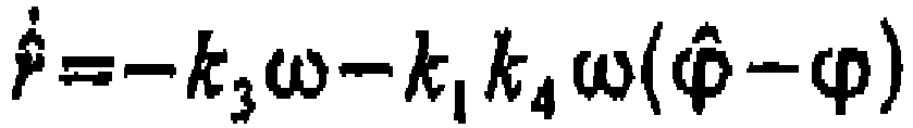 - (k1, k2, k3, k4) sont des constantes qui dépendent des caractéristiques mécaniques et électroniques dudit ensemble de dévidage (1) ;- (v, ω, ϕ) sont les mesures de la vitesse dudit tambour de traction (5), de la vélocité angulaire de ladite bobine (3) dévidée et de la position dudit élément de tension (6) ;- (ϕ̂,r̂) sont les estimations de la position dudit élément de tension (6) par rapport audit châssis de support (2) et du rayon de la bobine (3) dévidée ; (ϕ̂,r̂) sont les dérivées de ces estimations.
 - Ensemble de dévidage (1) selon une ou plusieurs des revendications précédentes, caractérisé en ce qu'il comprend, entre au moins deux bobines (3) et ledit élément de tension (6), un poste de jonction (8) conçu pour établir la connexion entre la portion d'extrémité du film continu (10) dévidé de la bobine (3) sur le point d'être épuisé et la portion d'extrémité du film supporté par l'autre bobine.
- Ensemble de dévidage (1) selon une ou plusieurs des revendications précédentes, caractérisé en ce que ledit élément de tension (6) comprend un rouleau égoutteur de tension (6a) qui est supporté de façon à pouvoir tourner, par l'intermédiaire dudit châssis de support (2), autour d'un axe de pivotement (101) correspondant.
- Procédé de contrôle du dévidage, par un tambour de traction motorisé (5), d'un film continu (10) à partir d'une bobine (3), un élément (6) pour la tension du film continu (10) dévidé se trouvant entre ladite bobine (3) et ledit tambour de traction (5), ledit procédé étant caractérisé en ce qu'il comprend une étape d'estimation, par des moyens d'estimation (20) du rayon (r) de la bobine (3) de film continu (10) dévidé en fonction des données relatives à la vélocité angulaire (ω) de la bobine (3) de film continu (10) dévidé, à la vitesse (v) dudit film continu (10) tiré par ledit tambour de traction (5) et à la position (ϕ) dudit élément de tension (6) par rapport à un châssis de support (2).
Applications Claiming Priority (2)
| Application Number | Priority Date | Filing Date | Title |
|---|---|---|---|
| ITVR2010A000003A IT1397684B1 (it) | 2010-01-15 | 2010-01-15 | Gruppo di sbobinatura, particolarmente per dispositivi di etichettatura |
| PCT/EP2011/050399 WO2011086128A1 (fr) | 2010-01-15 | 2011-01-13 | Ensemble de déroulage, en particulier pour dispositifs d'étiquetage |
Publications (2)
| Publication Number | Publication Date |
|---|---|
| EP2523883A1 EP2523883A1 (fr) | 2012-11-21 |
| EP2523883B1 true EP2523883B1 (fr) | 2018-04-04 |
Family
ID=42542908
Family Applications (1)
| Application Number | Title | Priority Date | Filing Date |
|---|---|---|---|
| EP11700177.6A Active EP2523883B1 (fr) | 2010-01-15 | 2011-01-13 | Ensemble de déroulage, en particulier pour dispositifs d'étiquetage |
Country Status (5)
| Country | Link |
|---|---|
| US (1) | US20120318905A1 (fr) |
| EP (1) | EP2523883B1 (fr) |
| ES (1) | ES2672899T3 (fr) |
| IT (1) | IT1397684B1 (fr) |
| WO (1) | WO2011086128A1 (fr) |
Families Citing this family (4)
| Publication number | Priority date | Publication date | Assignee | Title |
|---|---|---|---|---|
| CN107792703A (zh) * | 2017-11-21 | 2018-03-13 | 苏州工业园区天势科技有限公司 | 用于复合标签的传送定位机构 |
| JP7006938B2 (ja) * | 2018-12-21 | 2022-01-24 | 株式会社ミヤコシ | 連続ラベル用紙の抜き粕巻取り装置 |
| DE102019001174A1 (de) * | 2019-02-18 | 2020-08-20 | Giesecke+Devrient Currency Technology Gmbh | Vorrichtung für die Verpackung von Blattgut |
| CN111044852B (zh) * | 2019-11-12 | 2021-11-05 | 浙江耀阳新材料科技有限公司 | 一种薄膜击穿测试设备 |
Family Cites Families (8)
| Publication number | Priority date | Publication date | Assignee | Title |
|---|---|---|---|---|
| US4199118A (en) * | 1979-01-10 | 1980-04-22 | The Black Clawson Company | Method and apparatus for controlling the braking system for an unwinder |
| US4286757A (en) * | 1980-04-03 | 1981-09-01 | The Black Clawson Company | Method and apparatus for controlling the braking system for an unwinder |
| DE19520955C2 (de) * | 1995-06-08 | 1999-10-28 | Roland Man Druckmasch | Regelanordnung für Abwickeleinrichtungen für Bahnen |
| JP2003327354A (ja) * | 2002-05-10 | 2003-11-19 | Zuiko Corp | ウエブの継ぎ方法および継ぎ装置 |
| US7331542B2 (en) * | 2003-05-09 | 2008-02-19 | Intellipack | Film unwind system with hinged spindle and electronic control of web tension |
| ATE401278T1 (de) * | 2005-04-20 | 2008-08-15 | Windmoeller & Hoelscher | Verfahren zur steuerung und/oder überwachung einer bahnverarbeitenden maschine |
| DE102007049680A1 (de) * | 2007-10-17 | 2009-04-23 | Robert Bosch Gmbh | Verfahren zum Berechnen des Durchmessers einer Warenbahnwicklung auf einer Rolle sowie Wickelsteuerungssystem |
| TWI409207B (zh) * | 2010-12-01 | 2013-09-21 | Metal Ind Res & Dev Ct | 定張力捲繞裝置及其調控模組 |
-
2010
- 2010-01-15 IT ITVR2010A000003A patent/IT1397684B1/it active
-
2011
- 2011-01-13 EP EP11700177.6A patent/EP2523883B1/fr active Active
- 2011-01-13 ES ES11700177.6T patent/ES2672899T3/es active Active
- 2011-01-13 WO PCT/EP2011/050399 patent/WO2011086128A1/fr active Application Filing
- 2011-01-13 US US13/261,360 patent/US20120318905A1/en not_active Abandoned
Also Published As
| Publication number | Publication date |
|---|---|
| EP2523883A1 (fr) | 2012-11-21 |
| US20120318905A1 (en) | 2012-12-20 |
| ES2672899T3 (es) | 2018-06-18 |
| IT1397684B1 (it) | 2013-01-18 |
| ITVR20100003A1 (it) | 2011-07-16 |
| WO2011086128A1 (fr) | 2011-07-21 |
Similar Documents
| Publication | Publication Date | Title |
|---|---|---|
| EP2523883B1 (fr) | Ensemble de déroulage, en particulier pour dispositifs d'étiquetage | |
| US9138905B2 (en) | Method for calibrating the position of the slitter blades of a slitter-winder | |
| EP1839022B1 (fr) | Procede permettant de mesurer un profil de tension d'une bande et cylindre permettant de mettre en oeuvre ce procede | |
| CN100513283C (zh) | 一种药剂包装装置 | |
| EP0868378B1 (fr) | Procede et dispositif permettant de mesurer le diametre d'un rouleau de materiau en bande continue | |
| KR20090130332A (ko) | 웨브의 반송 제어 방법, 슬립량 측정 수단 및 반송 제어 장치 | |
| US20190088035A1 (en) | Methods and systems for dispensing | |
| CA2805532C (fr) | Procede de coupe precise a la dimension de tubes enroules sur une bobine et machine pour la mise en oeuvre dudit procede | |
| CN101201281A (zh) | 与幅面料张力测量有关的方法和系统 | |
| EP1636125B1 (fr) | Procede et dispositif de mesure de la tension d'un voile en mouvement | |
| JP6028496B2 (ja) | 巻取装置及び鋼板尾端停止位置の制御方法 | |
| US9540201B2 (en) | Method and apparatus for accelerating a roll to a target | |
| EP1044915A2 (fr) | Dispositif et méthode pour couper une bande | |
| JP2016011197A (ja) | シート材蛇行制御装置及びスリッター装置、並びにシート材蛇行制御方法 | |
| CA2320749A1 (fr) | Procede et appareil de deroulement | |
| US20100090052A1 (en) | Method and device for connecting two material webs | |
| EP3378808B1 (fr) | Procédé de commande de fonctionnement d'un enrouleur pour une bande de fibres | |
| EP3529554B1 (fr) | Dispositif de mesure de puissance adhésive | |
| US8939663B2 (en) | Ribbon tension control system and method for a ribbon printing system | |
| WO2007044252A3 (fr) | Système de contrôle qualité et procédé de transport d'un matériau en bande | |
| KR101304634B1 (ko) | 도금강판 스트립의 엔드마크 저감장치 및 방법 | |
| WO2012023799A3 (fr) | Dispositif de découpage d'un film mince pour panneau d'affichage et procédé de découpe utilisant ledit procédé | |
| EP2434254B1 (fr) | Dispositif de détection d'anomalie d'épaisseur de stock | |
| WO2003031297A1 (fr) | Procede et equipements de mesure d'un differentiel de vitesse angulaire | |
| US20100263331A1 (en) | Apparatus, a method, and a film for film wrapping |
Legal Events
| Date | Code | Title | Description |
|---|---|---|---|
| PUAI | Public reference made under article 153(3) epc to a published international application that has entered the european phase |
Free format text: ORIGINAL CODE: 0009012 |
|
| 17P | Request for examination filed |
Effective date: 20120711 |
|
| AK | Designated contracting states |
Kind code of ref document: A1 Designated state(s): AL AT BE BG CH CY CZ DE DK EE ES FI FR GB GR HR HU IE IS IT LI LT LU LV MC MK MT NL NO PL PT RO RS SE SI SK SM TR |
|
| DAX | Request for extension of the european patent (deleted) | ||
| 17Q | First examination report despatched |
Effective date: 20150720 |
|
| GRAP | Despatch of communication of intention to grant a patent |
Free format text: ORIGINAL CODE: EPIDOSNIGR1 |
|
| STAA | Information on the status of an ep patent application or granted ep patent |
Free format text: STATUS: GRANT OF PATENT IS INTENDED |
|
| INTG | Intention to grant announced |
Effective date: 20171016 |
|
| GRAS | Grant fee paid |
Free format text: ORIGINAL CODE: EPIDOSNIGR3 |
|
| GRAA | (expected) grant |
Free format text: ORIGINAL CODE: 0009210 |
|
| STAA | Information on the status of an ep patent application or granted ep patent |
Free format text: STATUS: THE PATENT HAS BEEN GRANTED |
|
| AK | Designated contracting states |
Kind code of ref document: B1 Designated state(s): AL AT BE BG CH CY CZ DE DK EE ES FI FR GB GR HR HU IE IS IT LI LT LU LV MC MK MT NL NO PL PT RO RS SE SI SK SM TR |
|
| REG | Reference to a national code |
Ref country code: GB Ref legal event code: FG4D |
|
| REG | Reference to a national code |
Ref country code: CH Ref legal event code: EP |
|
| REG | Reference to a national code |
Ref country code: AT Ref legal event code: REF Ref document number: 985367 Country of ref document: AT Kind code of ref document: T Effective date: 20180415 |
|
| REG | Reference to a national code |
Ref country code: IE Ref legal event code: FG4D |
|
| REG | Reference to a national code |
Ref country code: DE Ref legal event code: R096 Ref document number: 602011047094 Country of ref document: DE |
|
| REG | Reference to a national code |
Ref country code: ES Ref legal event code: FG2A Ref document number: 2672899 Country of ref document: ES Kind code of ref document: T3 Effective date: 20180618 |
|
| REG | Reference to a national code |
Ref country code: NL Ref legal event code: MP Effective date: 20180404 |
|
| REG | Reference to a national code |
Ref country code: LT Ref legal event code: MG4D |
|
| PG25 | Lapsed in a contracting state [announced via postgrant information from national office to epo] |
Ref country code: NL Free format text: LAPSE BECAUSE OF FAILURE TO SUBMIT A TRANSLATION OF THE DESCRIPTION OR TO PAY THE FEE WITHIN THE PRESCRIBED TIME-LIMIT Effective date: 20180404 |
|
| PG25 | Lapsed in a contracting state [announced via postgrant information from national office to epo] |
Ref country code: NO Free format text: LAPSE BECAUSE OF FAILURE TO SUBMIT A TRANSLATION OF THE DESCRIPTION OR TO PAY THE FEE WITHIN THE PRESCRIBED TIME-LIMIT Effective date: 20180704 Ref country code: FI Free format text: LAPSE BECAUSE OF FAILURE TO SUBMIT A TRANSLATION OF THE DESCRIPTION OR TO PAY THE FEE WITHIN THE PRESCRIBED TIME-LIMIT Effective date: 20180404 Ref country code: BG Free format text: LAPSE BECAUSE OF FAILURE TO SUBMIT A TRANSLATION OF THE DESCRIPTION OR TO PAY THE FEE WITHIN THE PRESCRIBED TIME-LIMIT Effective date: 20180704 Ref country code: SE Free format text: LAPSE BECAUSE OF FAILURE TO SUBMIT A TRANSLATION OF THE DESCRIPTION OR TO PAY THE FEE WITHIN THE PRESCRIBED TIME-LIMIT Effective date: 20180404 Ref country code: AL Free format text: LAPSE BECAUSE OF FAILURE TO SUBMIT A TRANSLATION OF THE DESCRIPTION OR TO PAY THE FEE WITHIN THE PRESCRIBED TIME-LIMIT Effective date: 20180404 Ref country code: LT Free format text: LAPSE BECAUSE OF FAILURE TO SUBMIT A TRANSLATION OF THE DESCRIPTION OR TO PAY THE FEE WITHIN THE PRESCRIBED TIME-LIMIT Effective date: 20180404 Ref country code: PL Free format text: LAPSE BECAUSE OF FAILURE TO SUBMIT A TRANSLATION OF THE DESCRIPTION OR TO PAY THE FEE WITHIN THE PRESCRIBED TIME-LIMIT Effective date: 20180404 |
|
| PG25 | Lapsed in a contracting state [announced via postgrant information from national office to epo] |
Ref country code: LV Free format text: LAPSE BECAUSE OF FAILURE TO SUBMIT A TRANSLATION OF THE DESCRIPTION OR TO PAY THE FEE WITHIN THE PRESCRIBED TIME-LIMIT Effective date: 20180404 Ref country code: GR Free format text: LAPSE BECAUSE OF FAILURE TO SUBMIT A TRANSLATION OF THE DESCRIPTION OR TO PAY THE FEE WITHIN THE PRESCRIBED TIME-LIMIT Effective date: 20180705 Ref country code: HR Free format text: LAPSE BECAUSE OF FAILURE TO SUBMIT A TRANSLATION OF THE DESCRIPTION OR TO PAY THE FEE WITHIN THE PRESCRIBED TIME-LIMIT Effective date: 20180404 Ref country code: RS Free format text: LAPSE BECAUSE OF FAILURE TO SUBMIT A TRANSLATION OF THE DESCRIPTION OR TO PAY THE FEE WITHIN THE PRESCRIBED TIME-LIMIT Effective date: 20180404 |
|
| REG | Reference to a national code |
Ref country code: AT Ref legal event code: MK05 Ref document number: 985367 Country of ref document: AT Kind code of ref document: T Effective date: 20180404 |
|
| PG25 | Lapsed in a contracting state [announced via postgrant information from national office to epo] |
Ref country code: PT Free format text: LAPSE BECAUSE OF FAILURE TO SUBMIT A TRANSLATION OF THE DESCRIPTION OR TO PAY THE FEE WITHIN THE PRESCRIBED TIME-LIMIT Effective date: 20180806 |
|
| REG | Reference to a national code |
Ref country code: DE Ref legal event code: R097 Ref document number: 602011047094 Country of ref document: DE |
|
| PG25 | Lapsed in a contracting state [announced via postgrant information from national office to epo] |
Ref country code: AT Free format text: LAPSE BECAUSE OF FAILURE TO SUBMIT A TRANSLATION OF THE DESCRIPTION OR TO PAY THE FEE WITHIN THE PRESCRIBED TIME-LIMIT Effective date: 20180404 Ref country code: EE Free format text: LAPSE BECAUSE OF FAILURE TO SUBMIT A TRANSLATION OF THE DESCRIPTION OR TO PAY THE FEE WITHIN THE PRESCRIBED TIME-LIMIT Effective date: 20180404 Ref country code: RO Free format text: LAPSE BECAUSE OF FAILURE TO SUBMIT A TRANSLATION OF THE DESCRIPTION OR TO PAY THE FEE WITHIN THE PRESCRIBED TIME-LIMIT Effective date: 20180404 Ref country code: CZ Free format text: LAPSE BECAUSE OF FAILURE TO SUBMIT A TRANSLATION OF THE DESCRIPTION OR TO PAY THE FEE WITHIN THE PRESCRIBED TIME-LIMIT Effective date: 20180404 Ref country code: SK Free format text: LAPSE BECAUSE OF FAILURE TO SUBMIT A TRANSLATION OF THE DESCRIPTION OR TO PAY THE FEE WITHIN THE PRESCRIBED TIME-LIMIT Effective date: 20180404 Ref country code: DK Free format text: LAPSE BECAUSE OF FAILURE TO SUBMIT A TRANSLATION OF THE DESCRIPTION OR TO PAY THE FEE WITHIN THE PRESCRIBED TIME-LIMIT Effective date: 20180404 |
|
| PLBE | No opposition filed within time limit |
Free format text: ORIGINAL CODE: 0009261 |
|
| STAA | Information on the status of an ep patent application or granted ep patent |
Free format text: STATUS: NO OPPOSITION FILED WITHIN TIME LIMIT |
|
| PG25 | Lapsed in a contracting state [announced via postgrant information from national office to epo] |
Ref country code: SM Free format text: LAPSE BECAUSE OF FAILURE TO SUBMIT A TRANSLATION OF THE DESCRIPTION OR TO PAY THE FEE WITHIN THE PRESCRIBED TIME-LIMIT Effective date: 20180404 |
|
| 26N | No opposition filed |
Effective date: 20190107 |
|
| PG25 | Lapsed in a contracting state [announced via postgrant information from national office to epo] |
Ref country code: SI Free format text: LAPSE BECAUSE OF FAILURE TO SUBMIT A TRANSLATION OF THE DESCRIPTION OR TO PAY THE FEE WITHIN THE PRESCRIBED TIME-LIMIT Effective date: 20180404 |
|
| PG25 | Lapsed in a contracting state [announced via postgrant information from national office to epo] |
Ref country code: MC Free format text: LAPSE BECAUSE OF FAILURE TO SUBMIT A TRANSLATION OF THE DESCRIPTION OR TO PAY THE FEE WITHIN THE PRESCRIBED TIME-LIMIT Effective date: 20180404 |
|
| REG | Reference to a national code |
Ref country code: CH Ref legal event code: PL |
|
| PG25 | Lapsed in a contracting state [announced via postgrant information from national office to epo] |
Ref country code: LU Free format text: LAPSE BECAUSE OF NON-PAYMENT OF DUE FEES Effective date: 20190113 |
|
| REG | Reference to a national code |
Ref country code: BE Ref legal event code: MM Effective date: 20190131 |
|
| REG | Reference to a national code |
Ref country code: IE Ref legal event code: MM4A |
|
| PG25 | Lapsed in a contracting state [announced via postgrant information from national office to epo] |
Ref country code: BE Free format text: LAPSE BECAUSE OF NON-PAYMENT OF DUE FEES Effective date: 20190131 |
|
| PG25 | Lapsed in a contracting state [announced via postgrant information from national office to epo] |
Ref country code: LI Free format text: LAPSE BECAUSE OF NON-PAYMENT OF DUE FEES Effective date: 20190131 Ref country code: CH Free format text: LAPSE BECAUSE OF NON-PAYMENT OF DUE FEES Effective date: 20190131 |
|
| PG25 | Lapsed in a contracting state [announced via postgrant information from national office to epo] |
Ref country code: IE Free format text: LAPSE BECAUSE OF NON-PAYMENT OF DUE FEES Effective date: 20190113 |
|
| PG25 | Lapsed in a contracting state [announced via postgrant information from national office to epo] |
Ref country code: TR Free format text: LAPSE BECAUSE OF FAILURE TO SUBMIT A TRANSLATION OF THE DESCRIPTION OR TO PAY THE FEE WITHIN THE PRESCRIBED TIME-LIMIT Effective date: 20180404 |
|
| PG25 | Lapsed in a contracting state [announced via postgrant information from national office to epo] |
Ref country code: MT Free format text: LAPSE BECAUSE OF NON-PAYMENT OF DUE FEES Effective date: 20190113 |
|
| PG25 | Lapsed in a contracting state [announced via postgrant information from national office to epo] |
Ref country code: CY Free format text: LAPSE BECAUSE OF FAILURE TO SUBMIT A TRANSLATION OF THE DESCRIPTION OR TO PAY THE FEE WITHIN THE PRESCRIBED TIME-LIMIT Effective date: 20180404 |
|
| PG25 | Lapsed in a contracting state [announced via postgrant information from national office to epo] |
Ref country code: IS Free format text: LAPSE BECAUSE OF FAILURE TO SUBMIT A TRANSLATION OF THE DESCRIPTION OR TO PAY THE FEE WITHIN THE PRESCRIBED TIME-LIMIT Effective date: 20180804 |
|
| PG25 | Lapsed in a contracting state [announced via postgrant information from national office to epo] |
Ref country code: HU Free format text: LAPSE BECAUSE OF FAILURE TO SUBMIT A TRANSLATION OF THE DESCRIPTION OR TO PAY THE FEE WITHIN THE PRESCRIBED TIME-LIMIT; INVALID AB INITIO Effective date: 20110113 |
|
| PG25 | Lapsed in a contracting state [announced via postgrant information from national office to epo] |
Ref country code: MK Free format text: LAPSE BECAUSE OF FAILURE TO SUBMIT A TRANSLATION OF THE DESCRIPTION OR TO PAY THE FEE WITHIN THE PRESCRIBED TIME-LIMIT Effective date: 20180404 |
|
| REG | Reference to a national code |
Ref country code: DE Ref legal event code: R082 Ref document number: 602011047094 Country of ref document: DE Representative=s name: SCHIEBER - FARAGO PATENTANWAELTE, DE Ref country code: DE Ref legal event code: R082 Ref document number: 602011047094 Country of ref document: DE Representative=s name: FARAGO PATENTANWALTSGESELLSCHAFT MBH, DE |
|
| REG | Reference to a national code |
Ref country code: DE Ref legal event code: R082 Ref document number: 602011047094 Country of ref document: DE Representative=s name: SCHIEBER - FARAGO PATENTANWAELTE, DE |
|
| PGFP | Annual fee paid to national office [announced via postgrant information from national office to epo] |
Ref country code: IT Payment date: 20230103 Year of fee payment: 13 |
|
| P01 | Opt-out of the competence of the unified patent court (upc) registered |
Effective date: 20230529 |
|
| PGFP | Annual fee paid to national office [announced via postgrant information from national office to epo] |
Ref country code: GB Payment date: 20231219 Year of fee payment: 14 |
|
| PGFP | Annual fee paid to national office [announced via postgrant information from national office to epo] |
Ref country code: FR Payment date: 20231219 Year of fee payment: 14 |
|
| PGFP | Annual fee paid to national office [announced via postgrant information from national office to epo] |
Ref country code: ES Payment date: 20240202 Year of fee payment: 14 |
|
| PGFP | Annual fee paid to national office [announced via postgrant information from national office to epo] |
Ref country code: DE Payment date: 20231219 Year of fee payment: 14 |