EP2523764B1 - Regelverfahren für den giessspiegel einer stranggiesskokille - Google Patents
Regelverfahren für den giessspiegel einer stranggiesskokille Download PDFInfo
- Publication number
- EP2523764B1 EP2523764B1 EP10798820.6A EP10798820A EP2523764B1 EP 2523764 B1 EP2523764 B1 EP 2523764B1 EP 10798820 A EP10798820 A EP 10798820A EP 2523764 B1 EP2523764 B1 EP 2523764B1
- Authority
- EP
- European Patent Office
- Prior art keywords
- value
- controller
- control method
- continuous casting
- facility
- Prior art date
- Legal status (The legal status is an assumption and is not a legal conclusion. Google has not performed a legal analysis and makes no representation as to the accuracy of the status listed.)
- Active
Links
Images


Classifications
-
- B—PERFORMING OPERATIONS; TRANSPORTING
- B22—CASTING; POWDER METALLURGY
- B22D—CASTING OF METALS; CASTING OF OTHER SUBSTANCES BY THE SAME PROCESSES OR DEVICES
- B22D11/00—Continuous casting of metals, i.e. casting in indefinite lengths
- B22D11/16—Controlling or regulating processes or operations
-
- B—PERFORMING OPERATIONS; TRANSPORTING
- B22—CASTING; POWDER METALLURGY
- B22D—CASTING OF METALS; CASTING OF OTHER SUBSTANCES BY THE SAME PROCESSES OR DEVICES
- B22D11/00—Continuous casting of metals, i.e. casting in indefinite lengths
- B22D11/16—Controlling or regulating processes or operations
- B22D11/18—Controlling or regulating processes or operations for pouring
Definitions
- Such a control method is for example from the US 5,921,313 A known.
- a vibration compensator is provided which compensates Bulgingschwingungen.
- the present invention further relates to a computer program comprising machine code which is directly executable by a control device for a continuous casting plant and whose execution by the control device causes the control device to regulate the casting level of a continuous casting mold of the continuous casting plant according to such a control method.
- the present invention further relates to a control device for a continuous casting plant, which is designed in this way is that she carries out such a control procedure during operation.
- the present invention relates to a continuous casting plant, which is controlled by such a control device.
- the pouring level in the continuous casting mold is influenced, inter alia, by jump-shaped disturbances in an undesirable manner.
- unwanted disturbances are the so-called “clogging” and “unclogging”, that is, the sudden caking or breaking of aluminum oxide in the feed channel of the mold.
- the pouring mirror can be influenced by jerky removal of the metal strand in an undesirable manner. Any disturbance of the pouring mirror means a loss of quality of the strand. Mold level fluctuations should therefore be kept as low as possible.
- the G manharmadorregler is usually designed as a PI controller or as a PID controller, which also has several additional functions to combat specific interference.
- An example of such an additional function is the abovementioned compensation of bulging vibrations.
- the integral portion of the mold leveler is required in the prior art to locate and hold the steady state desired position for the closure.
- the pouring level regulator In the case of sudden inflow disturbances or withdrawal disorders, the pouring level regulator must react quickly.
- the integral component of the G manLitereglers must settle quickly to a new desired position for the closure device.
- An integral component with a short reset time will respond quickly, but will overshoot.
- An integral component with a large reset time will not overshoot, but it will react too slowly. In both cases, the pouring mirror can not be returned to the desired level quickly yet still reliably damped to its desired value.
- the object of the present invention is to provide ways to achieve a more accurate control.
- control method having the features of claim 1.
- Advantageous embodiments of the control method according to the invention are the subject of the dependent claims 2 to 9.
- the expected value for the casting level is subtracted without delay from the measured actual value of the casting level.
- the start-up factor has an initial value at the beginning of the control method and is steadily increased to a final value in the course of the control method.
- the G recognizespiegelregler is usually designed as a controller with integral behavior, for example, as a PI controller or as a PID controller. Due to its integral behavior, the casting level controller has a readjustment time.
- the reset time is characteristic of how fast the G stealaptregler reacts to disturbances. In particular, the G stealspiegelregler reacts quickly to interference with a small reset time, but tends to overshoot. Conversely, the G stealaptregler reacts stable reactivity to G stealspiegelminien at a large readjustment, but reacts slower.
- the reset time of the G fauxreglers is increased during and / or after increasing the Aufschaltides from an initial value to a final value.
- the initial value and the final value of the reset time are values other than the initial value and the end value of the closing factor.
- the final value of the reset time is finite. In this case, an integral part of the G manLitereglers is maintained in each operating condition. However, it is also possible that the final value of the reset time is infinite. This corresponds to a complete shutdown of the Integralanteils of the G manLitereglers. If the G manLiteregler is formed, for example, as a PI controller, it works with a reset time of infinity only as a P-controller. Likewise, for example, a PID controller can be reduced to a PD controller by increasing the reset time to the value infinite.
- the differential controller is (at least) designed as a proportional controller. It therefore has a proportional gain.
- the proportional gain is increased during and / or after increasing the turn-on factor from an initial value to a final value.
- the initial value and the final value of the proportional gain are values other than the initial value and the end value of the switch-on factor.
- the initial value of the proportional gain of the differential controller may be determined as needed.
- the initial value is equal to a proportional gain of the G manLitereglers.
- the differential controller can be designed, for example, as a PI controller or as an even more complex controller. However, it is preferred that the differential controller is designed as a pure P controller.
- the present invention is further achieved by a computer program of the aforementioned type, wherein the execution of the computer program causes the control device controls the pouring level of the continuous casting mold according to a control method according to the invention.
- the computer program can for example be stored on a data carrier in machine-readable form.
- the data carrier may in particular be part of the control device.
- the object is further achieved by a control device for a continuous casting plant, which is designed such that it carries out an inventive control method during operation.
- a continuous casting plant which is controlled by a control device according to the invention.
- a continuous casting plant has a continuous casting mold 1.
- liquid metal 3 is poured over a dip tube, for example steel or aluminum.
- the inflow of the liquid metal 3 into the continuous casting mold 1 is adjusted by means of a closure device 4.
- the closure device 4 Is shown in FIG. 1 an embodiment of the closure device 4 as a sealing plug.
- a position of the closure device 4 corresponds to a stroke position of the sealing plug.
- the closure device 4 may be designed as a slide.
- the closed position corresponds to the slider position.
- the liquid metal 3 contained in the continuous casting mold 1 is cooled by means of cooling devices, so that a strand shell 5 is formed. However, the core 6 of the metal strand 7 is still liquid. He freezes later.
- the cooling facilities are in FIG. 1 not shown.
- the partially solidified metal strand 7 (solidified strand shell 5, liquid core 6) is withdrawn by means of a discharge device 8 from the continuous casting mold 1.
- the pouring mirror 9 of the liquid metal 3 in the continuous casting mold 1 should be kept as constant as possible.
- a withdrawal speed v at which the partially solidified metal strand 7 is withdrawn from the continuous casting mold 1 is generally constant. Therefore, both in the prior art and in the present invention, the position of the closure device 4 is tracked to adjust the inflow of the liquid metal 3 in the continuous casting mold 1 so that the casting level 9 is kept as constant as possible.
- an actual value hG of the pouring mirror 9 is detected.
- the actual value hG is fed to a control device 11 for the continuous casting plant.
- the control device 11 determines, according to a control method, which is explained in more detail below, a desired position p * to be assumed by the closure device 4.
- the closure device 4 is then controlled accordingly by the control device 11.
- the control device 11 outputs a corresponding actuating signal to an adjusting device 12 for the closure device 4.
- the adjusting device 12 may be, for example, a hydraulic cylinder unit.
- an actual position p of the closure device 4 is further detected by means of a corresponding measuring device 13 (known as such) and fed to the control device 11.
- a closed-loop control of the closure position takes place.
- a pure control open loop control
- the control device 11 is designed such that it carries out an inventive control method during operation.
- the operation of the control device 11 is determined by a computer program 14, with which the control device 11 is programmed.
- the computer program 14 is stored within the control device 11 in a data carrier 15, for example a flash EPROM.
- the data carrier 15 is part of the control device 11. The storage takes place in machine-readable form.
- the computer program 14 may have been supplied to the control device 11 via a mobile data carrier 16, for example a USB memory stick (shown) or an SD memory card (not shown). Also on the mobile data carrier 16, the computer program 14 is stored in machine-readable form. Alternatively, it is possible to supply the computer program 14 to the control device 11 via a computer network connection or a programming device.
- a mobile data carrier 16 for example a USB memory stick (shown) or an SD memory card (not shown).
- the computer program 14 is stored in machine-readable form.
- the computer program 14 comprises machine code 17, which is directly executable by the control device 11.
- the execution of the machine code 17 by the control device 11 causes the control device 11 to control the pouring level 9 of the continuous casting mold 1 according to a control method according to the invention. This control method will be described below in connection with the FIGS. 2 and 3 explained in more detail.
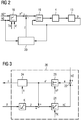
- FIG. 2 shows a control arrangement implemented by the control device 11.
- the operation of the control arrangement of FIG. 2 enables a control method according to the invention for the pouring mirror 9 of the continuous casting mold 1.
- the regulating arrangement has a pouring-mirror regulator 18. Based on a setpoint hG * for the pouring mirror 9 and the actual value hG for the pouring mirror 9 detected by the measuring device 10, the pouring-mirror regulator 18 determines the setpoint position p * for the closure device 4 according to a controller characteristic.
- the regulator characteristic of the pouring-glass regulator 18 is shown in FIG FIG. 2 proportional-integral. However, alternatively other control characteristics are possible, for example PID. Regardless of its specific embodiment of the G manLiteregler 18, however, is preferably designed as a controller with Integral .
- the desired position p * for the closure device 4 is supplied to the closure device 4.
- the setting of the closure device 4 is usually regulated.
- the in FIG. 2 is shown, the reference position is fed to a position controller 19, which also the actual position p of the closure device 4 is supplied.
- the position controller 19 may be formed, for example, as a P controller.
- the actual position p of the closure device 4 acts on the actual pouring mirror 9 due to the inflow of liquid metal 3 which has thus been set.
- the actual value hG of the pouring mirror 9 is detected and, as already mentioned, fed to the G manaptreagler 18.
- Störssennkompensators 20 The structure and operation of the Störssennkompensators 20 are described below in conjunction with FIG. 3 explained in more detail.
- the disturbance compensator 20 includes, inter alia, an integrator 21.
- An integration time constant TK of the integrator 21 is preferably the cross section of the continuous casting mold 1, the measuring range ⁇ hG of the measuring device 10 for the actual value hG of the pouring mirror 9 and the measuring range ⁇ p of the measuring device 13 for the actual position p as well determines the characteristic K of the closure device 4.
- the concrete value for the characteristic curve K results from a fictitious operating point of the closure device 4, that is to say the position of the closure device 4, in which the inflow of liquid metal 3 into the continuous casting mold 1 and the amount of metal withdrawn at the given withdrawal speed v are in equilibrium stand.
- the integrator 21 is an input value supplied within the Störssennkompensators 20, which will be discussed later.
- the integrator 21 determines by integrating the input value according to the integration time constant TK an output signal hE.
- the output signal hE corresponds to an expected value hE for the pouring mirror 9.
- the expected value hE is fed within the disturbance variable compensator 20 to a node 22, to which furthermore the actual value hG of the pouring mirror 9 is supplied. In node 22, the expected value hE is subtracted from the actual value hG. The difference is referred to below by the reference e.
- the measuring device 10 for the pouring mirror 9 is delayed.
- the actual value hG of the pouring mirror 9 therefore has a delay time. It is possible to actively delay the expected value hE by a delay element accordingly.
- the delay element would have to be arranged between the integrator 21 and the node 22 for this purpose. Preferably, however, no such delay element is present.
- the expected value hE for the pouring mirror 9 is therefore preferably subtracted without delay from the measured actual value hG of the pouring mirror 9.
- the difference e is fed to a differential controller 23 within the disturbance compensator 20.
- the differential controller 23 uses the difference e to determine a controller output signal e '.
- the differential controller 23 may be formed as needed.
- the differential controller 23 may be formed as a PI controller. It is preferred that the differential controller 23 is designed as a pure P controller. Regardless of its specific embodiment, however, the differential controller 23 has a proportional gain kP.
- the controller output signal e 'already corresponds to a disturbance compensation value z, which is to be switched to the desired position p * of the closure device 4.
- the regulator output signal e ' is multiplied in a multiplier 24 by a breakdown factor k.
- the product of contact factor k and controller output signal e ' corresponds to the disturbance compensation value z.
- the contact factor k can have a fixed value.
- the override factor k it is possible for the override factor k to have the value one constant.
- the override factor k in accordance with the representation of FIG. 4 has an initial value kA at the beginning of the control method and is steadily increased to a final value kE in the course of the control method.
- the initial value kA is zero and the final value kE is one.
- an inflow signal Z On the controller output signal e 'is further connected within the Störssennkompensators 20, an inflow signal Z.
- the inflow signal Z is according to FIG. 3 derived from the actual position p of the closure device 4.
- the inflow signal Z can be determined by determining the inflow Z based on the actual position p of the closure device 4 and the characteristic curve K of the closure device 4, which results at the given actual position p of the closure device 4.
- the upshift result is supplied within the disturbance compensator 20 to the integrator 21 as its input signal.
- the G garbageLiteregler 18 is preferably designed as a controller with integral behavior.
- the pouring-mirror regulator 18 therefore preferably has an adjusting time TN.
- the reset time TN is characteristic of the integral behavior of the G manLitereglers 18th
- the reset time TN of the G confuseLitereglers 18 is kept constant over time.
- the reset time TN of the mold level regulator 18 is increased during and / or after the increase of the switch-on factor k from an initial value TA to a final value TE.
- FIG. 4 shows an increase of the reset time TN during the increase of the connection factor k.
- FIG. 5 shows an increase of the reset time TN after increasing the connection factor k.
- increasing the reset time TN may be started by increasing the startup factor k and beyond the time when the override factor k reaches its final value kE. It is also possible to start with the increase of the reset time TN at a time at which the override factor k is already greater than its initial value kA, but still smaller than its final value kE.
- the final value TE of the reset time TN is finite. In this case, even after reaching the final value TE of the reset time TN a - albeit reduced - integral behavior of the G manLitereglers 18 maintained.
- it is according to the dashed line of the 4 and 5 possible to increase the reset time TN to the final value TE infinity. In this case, the integral behavior of the G manLitereglers 18 is completely suppressed.
- the proportional gain kP of the differential regulator 23 it is possible for the proportional gain kP of the differential regulator 23 to be constant throughout the control process. However, it is preferred according to the representations of 4 and 5 in that the proportional gain kP during (see FIG. 4 ) and / or after (see FIG. 5 ) increasing the turn-on factor k from an initial value kPA to a final value kPE.
- the initial value kPA of the proportional gain kP of the differential controller 23 may be selected as needed.
- the initial value kPA is equal to a proportional gain k 'of the G manLitereglers 18th
- the disturbance variable compensator 20 operates dynamically more favorably than the integral component of the mold level regulator 18.
- the reset time TN of the mold level regulator 18 can therefore be selected to be larger, because the integral component only has to compensate for minor inaccuracies. In some cases, the integral component can even be omitted (reset time TN against infinity).
Landscapes
- Engineering & Computer Science (AREA)
- Mechanical Engineering (AREA)
- Control Of Non-Electrical Variables (AREA)
- Continuous Casting (AREA)
- Feedback Control In General (AREA)
Description
- Die vorliegende Erfindung betrifft ein Regelverfahren für den Gießspiegel einer Stranggießkokille,
- wobei der Zufluss flüssigen Metalls in die Stranggießkokille mittels einer Verschlusseinrichtung eingestellt und der teilerstarrte Metallstrang mittels einer Abzugseinrichtung aus der Stranggießkokille abgezogen wird,
- wobei ein gemessener Istwert des Gießspiegels einem Gießspiegelregler zugeführt wird, der anhand des Istwerts und eines korrespondierenden Sollwerts eine Sollstellung für die Verschlusseinrichtung ermittelt und der Verschlusseinrichtung zuführt,
- wobei der gemessene Istwert und eine Iststellung der Verschlusseinrichtung einem Störgrößenkompensator zugeführt werden,
- wobei innerhalb des Störgrößenkompensators ein Erwartungswert für den Gießspiegel ermittelt und vom gemessenen Istwert des Gießspiegels subtrahiert wird.
- Ein derartiges Regelverfahren ist beispielsweise aus der
US 5,921,313 A bekannt. Bei dem bekannten Regelverfahren ist ein Schwingungskompensator vorhanden, der Bulgingschwingungen kompensiert. - Die vorliegende Erfindung betrifft weiterhin ein Computerprogramm, das Maschinencode umfasst, der von einer Steuereinrichtung für eine Stranggießanlage unmittelbar ausführbar ist und dessen Ausführung durch die Steuereinrichtung bewirkt, dass die Steuereinrichtung den Gießspiegel einer Stranggießkokille der Stranggießanlage gemäß einem derartigen Regelverfahren regelt.
- Die vorliegende Erfindung betrifft weiterhin eine Steuereinrichtung für eine Stranggießanlage, die derart ausgebildet ist, dass sie im Betrieb ein derartiges Regelverfahren ausführt.
- Schließlich betrifft die vorliegende Erfindung eine Stranggießanlage, die von einer derartigen Steuereinrichtung gesteuert wird.
- Der Gießspiegel in der Stranggießkokille wird unter anderem durch sprungförmige Störungen in unerwünschter Weise beeinflusst. Beispiele derartiger unerwünschter Störungen sind das sogenannte "Clogging" und "Unclogging", das heißt das plötzliche Anbacken oder Abbrechen von Aluminiumoxid im Zulaufkanal der Kokille. Ebenso kann der Gießspiegel durch ruckartiges Abziehen des Metallstrangs in unerwünschter Weise beeinflusst werden. Jede Störung des Gießspiegels bedeutet einen Qualitätsverlust des Strangs. Gießspiegelschwankungen sollten deshalb so gering wie möglich gehalten werden.
- Im Stand der Technik ist der Gießspiegelregler meist als PI-Regler oder als PID-Regler ausgebildet, der zusätzlich mehrere Zusatzfunktionen zur Bekämpfung spezifischer Störungen aufweist. Ein Beispiel einer derartigen Zusatzfunktion ist die obenstehend erwähnte Kompensation von Bulgingschwingungen. Der Integralanteil des Gießspiegelreglers ist im Stand der Technik erforderlich, um die stationäre Sollstellung für die Verschlusseinrichtung zu finden und zu halten.
- Bei plötzlichen Zuflussstörungen oder Abzugsstörungen muss der Gießspiegelregler schnell reagieren. Insbesondere muss der Integralanteil des Gießspiegelreglers schnell auf eine neue Sollstellung für die Verschlusseinrichtung einschwingen. Ein Integralanteil mit kleiner Nachstellzeit wird zwar schnell reagieren, dafür aber überschwingen. Ein Integralanteil mit großer Nachstellzeit wird zwar nicht überschwingen, dafür aber zu langsam reagieren. In beiden Fällen kann der Gießspiegel nicht in dem gewünschten Maß wieder schnell und trotzdem zuverlässig gedämpft auf seinen Sollwert zurückgebracht werden.
- Die Aufgabe der vorliegenden Erfindung besteht darin, Möglichkeiten zu schaffen, eine genauere Regelung zu erreichen.
- Die Aufgabe wird durch ein Regelverfahren mit den Merkmalen des Anspruchs 1 gelöst. Vorteilhafte Ausgestaltungen des erfindungsgemäßen Regelverfahrens sind Gegenstand der abhängigen Ansprüche 2 bis 9.
- Erfindungsgemäß ist vorgesehen, ein Regelverfahren der eingangs genannten Art dadurch auszugestalten,
- dass die Differenz innerhalb des Störgrößenkompensators einem Differenzregler zugeführt wird, der daraus ein Reglerausgangssignal ermittelt,
- dass das Reglerausgangssignal einerseits mit einem Aufschaltfaktor multipliziert wird und das mit dem Aufschaltfaktor multiplizierte Reglerausgangssignal als Störgrößenkompensationswert auf die Sollstellung aufgeschaltet wird,
- dass auf das Reglerausgangssignal andererseits ein aus der Iststellung abgeleitetes Zuflusssignal aufgeschaltet wird und das Aufschaltergebnis innerhalb des Störgrößenkompensators einem Integrator zugeführt wird, dessen Ausgangssignal dem Erwartungswert für den Gießspiegel entspricht.
- In einer bevorzugten Ausgestaltung der vorliegenden Erfindung ist vorgesehen, dass der Erwartungswert für den Gießspiegel unverzögert vom gemessenen Istwert des Gießspiegels subtrahiert wird. Durch diese Vorgehensweise kann ein schnelleres Reagieren auf Gießspiegelstörungen erreicht werden.
- Vorzugsweise ist vorgesehen, dass der Aufschaltfaktor zu Beginn des Regelverfahrens einen Anfangswert aufweist und im Laufe des Regelverfahrens stetig auf einen Endwert erhöht wird. Durch diese Vorgehensweise ist insbesondere ein störungsfreies Zuschalten des Störgrößenkompensators möglich. Dies gilt ganz besonders, wenn der Anfangswert des Aufschaltfaktors Null ist und der Endwert des Aufschaltfaktors Eins ist.
- Der Gießspiegelregler ist üblicherweise als Regler mit Integralverhalten ausgebildet, beispielsweise als PI-Regler oder als PID-Regler. Auf Grund seines Integralverhaltens weist der Gießspiegelregler eine Nachstellzeit auf. Die Nachstellzeit ist dafür charakteristisch, wie schnell der Gießspiegelregler auf Störungen reagiert. Insbesondere reagiert der Gießspiegelregler bei einer kleinen Nachstellzeit schnell auf Störungen, neigt aber zu Überschwingungen. Umgekehrt reagiert der Gießspiegelregler bei großer Nachstellzeit zwar stabil auf Gießspiegelstörungen, reagiert dafür aber langsamer. In einer bevorzugten Ausgestaltung der vorliegenden Erfindung ist vorgesehen, dass die Nachstellzeit des Gießspiegelreglers während und/oder nach dem Erhöhen des Aufschaltfaktors von einem Anfangswert auf einen Endwert erhöht wird. Der Anfangswert und der Endwert der Nachstellzeit sind selbstverständlich andere Werte als der Anfangswert und der Endwert des Aufschaltfaktors.
- Es ist möglich, dass der Endwert der Nachstellzeit endlich ist. In diesem Fall bleibt ein Integralanteil des Gießspiegelreglers in jedem Betriebszustand erhalten. Es ist jedoch ebenso möglich, dass der Endwert der Nachstellzeit unendlich ist. Dies entspricht einem vollständigen Abschalten des Integralanteils des Gießspiegelreglers. Wenn der Gießspiegelregler beispielsweise als PI-Regler ausgebildet ist, arbeitet er mit einer Nachstellzeit von unendlich nur noch als P-Regler. Ebenso kann beispielsweise ein PID-Regler durch Erhöhen der Nachstellzeit auf den Wert unendlich zu einem PD-Regler reduziert werden.
- Der Differenzregler ist (zumindest) als Proportionalregler ausgebildet. Er weist daher eine Proportionalverstärkung auf. In einer bevorzugten Ausgestaltung der vorliegenden Erfindung wird die Proportionalverstärkung während und/oder nach dem Erhöhen des Aufschaltfaktors von einem Anfangswert auf einen Endwert erhöht. Der Anfangswert und der Endwert der Proportionalverstärkung sind hierbei andere Werte als der Anfangswert und der Endwert des Aufschaltfaktors.
- Das Erhöhen der Proportionalverstärkung des Differenzreglers und das Erhöhen der Nachstellzeit des Gießspiegelreglers sind unabhängig voneinander. Es ist also möglich, nur den einen Wert zu erhöhen und den anderen Wert konstant zu halten oder beide Werte zu erhöhen. Auch kann in dem Fall, dass beide Werte erhöht werden, das Erhöhen in voneinander verschiedenen Zeitfenstern erfolgen.
- Der Anfangswert der Proportionalverstärkung des Differenzreglers kann nach Bedarf bestimmt sein. Vorzugsweise ist der Anfangswert gleich einer Proportionalverstärkung des Gießspiegelreglers.
- Der Differenzregler kann beispielsweise als PI-Regler oder als noch komplexerer Regler ausgebildet sein. Bevorzugt ist jedoch, dass der Differenzregler als reiner P-Regler ausgebildet ist.
- Die vorliegende Erfindung wird weiterhin durch ein Computerprogramm der eingangs genannten Art gelöst, wobei die Ausführung des Computerprogramms bewirkt, dass die Steuereinrichtung den Gießspiegel der Stranggießkokille gemäß einem erfindungsgemäßen Regelverfahren regelt. Das Computerprogramm kann beispielsweise auf einem Datenträger in maschinenlesbarer Form gespeichert sein. Der Datenträger kann insbesondere Bestandteil der Steuereinrichtung sein.
- Die Aufgabe wird weiterhin durch eine Steuereinrichtung für eine Stranggießanlage gelöst, die derart ausgebildet ist, dass sie im Betrieb ein erfindungsgemäßes Regelverfahren ausführt. Schließlich wird die Aufgabe durch eine Stranggießanlage gelöst, die von einer erfindungsgemäßen Steuereinrichtung gesteuert wird.
- Weitere Vorteile und Einzelheiten ergeben sich aus der nachfolgenden Beschreibung von Ausführungsbeispielen in Verbindung mit den Zeichnungen. Es zeigen in Prinzipdarstellung:
- FIG 1
- schematisch eine Stranggießanlage,
- FIG 2
- ein regelungstechnisches Blockschaltbild einer Regelanordnung,
- FIG 3
- schematisch die interne Struktur eines Störgrößenkompensators und
- FIG 4 und 5
- Zeitdiagramme.
- Gemäß
FIG 1 weist eine Stranggießanlage eine Stranggießkokille 1 auf. In die Stranggießkokille 1 wird über ein Tauchrohr 2 flüssiges Metall 3 gegossen, beispielsweise Stahl oder Aluminium. Der Zufluss des flüssigen Metalls 3 in die Stranggießkokille 1 wird mittels einer Verschlusseinrichtung 4 eingestellt. Dargestellt ist inFIG 1 eine Ausbildung der Verschlusseinrichtung 4 als Verschlussstopfen. In diesem Fall entspricht eine Stellung der Verschlusseinrichtung 4 einer Hubposition des Verschlussstopfens. Alternativ kann die Verschlusseinrichtung 4 als Schieber ausgebildet sein. In diesem Fall entspricht die Verschlussstellung der Schieberposition. - Das in der Stranggießkokille 1 befindliche flüssige Metall 3 wird mittels Kühleinrichtungen gekühlt, so dass sich eine Strangschale 5 bildet. Der Kern 6 des Metallstrangs 7 ist jedoch noch flüssig. Er erstarrt erst später. Die Kühleinrichtungen sind in
FIG 1 nicht mit dargestellt. Der teilerstarrte Metallstrang 7 (erstarrte Strangschale 5, flüssiger Kern 6) wird mittels einer Abzugseinrichtung 8 aus der Stranggießkokille 1 abgezogen. - Der Gießspiegel 9 des flüssigen Metalls 3 in der Stranggießkokille 1 soll möglichst konstant gehalten werden. Eine Abzugsgeschwindigkeit v, mit welcher der teilerstarrte Metallstrang 7 aus der Stranggießkokille 1 abgezogen wird, ist in der Regel konstant. Daher wird - sowohl im Stand der Technik als auch bei der vorliegenden Erfindung - die Stellung der Verschlusseinrichtung 4 nachgeführt, um den Zufluss des flüssigen Metalls 3 in die Stranggießkokille 1 so einzustellen, dass der Gießspiegel 9 möglichst konstant gehalten wird.
- Mittels einer entsprechenden Messeinrichtung 10 (als solche bekannt) wird ein Istwert hG des Gießspiegels 9 erfasst. Der Istwert hG wird einer Steuereinrichtung 11 für die Stranggießanlage zugeführt. Die Steuereinrichtung 11 ermittelt gemäß einem Regelverfahren, das nachstehend näher erläutert wird, eine von der Verschlusseinrichtung 4 anzunehmende Sollstellung p*. Die Verschlusseinrichtung 4 wird sodann von der Steuereinrichtung 11 entsprechend angesteuert. In der Regel gibt die Steuereinrichtung 11 ein entsprechendes Stellsignal an eine Verstelleinrichtung 12 für die Verschlusseinrichtung 4 aus. Bei der Verstelleinrichtung 12 kann es sich beispielsweise um eine Hydraulikzylindereinheit handeln.
- In der Regel wird weiterhin mittels einer entsprechenden Messeinrichtung 13 (als solche bekannt) eine Iststellung p der Verschlusseinrichtung 4 erfasst und der Steuereinrichtung 11 zugeführt. Üblicherweise erfolgt daher ein Regeln (closed loop control) der Verschlussposition. Alternativ wäre auch eine reine Steuerung (open loop control) möglich.
- Die Steuereinrichtung 11 ist derart ausgebildet, dass sie im Betrieb ein erfindungsgemäßes Regelverfahren ausführt. In der Regel wird die Wirkungsweise der Steuereinrichtung 11 durch ein Computerprogramm 14 bestimmt, mit dem die Steuereinrichtung 11 programmiert ist. Zu diesem Zweck ist das Computerprogramm 14 innerhalb der Steuereinrichtung 11 in einem Datenträger 15 gespeichert, beispielsweise einem Flash-EPROM. Der Datenträger 15 ist Bestandteil der Steuereinrichtung 11. Die Speicherung erfolgt in maschinenlesbarer Form.
- Das Computerprogramm 14 kann der Steuereinrichtung 11 über einen mobilen Datenträger 16 zugeführt worden sein, beispielsweise einen USB-Memorystick (dargestellt) oder eine SD-Speicherkarte (nicht dargestellt). Auch auf dem mobilen Datenträger 16 ist das Computerprogramm 14 in maschinenlesbarer Form gespeichert. Alternativ ist es möglich, das Computerprogramm 14 der Steuereinrichtung 11 über eine Rechnernetzanbindung oder ein Programmiergerät zuzuführen.
- Das Computerprogramm 14 umfasst Maschinencode 17, der von der Steuereinrichtung 11 unmittelbar ausführbar ist. Das Ausführen des Maschinencodes 17 durch die Steuereinrichtung 11 bewirkt, dass die Steuereinrichtung 11 den Gießspiegel 9 der Stranggießkokille 1 gemäß einem erfindungsgemäßen Regelverfahren regelt. Dieses Regelverfahren wird nachfolgend in Verbindung mit den
FIG 2 und 3 näher erläutert. -
FIG 2 zeigt eine von der Steuereinrichtung 11 implementierte Regelanordnung. Der Betrieb der Regelanordnung vonFIG 2 ermöglicht ein erfindungsgemäßes Regelverfahren für den Gießspiegel 9 der Stranggießkokille 1. - Gemäß
FIG 2 weist die Regelanordnung einen Gießspiegelregler 18 auf. Der Gießspiegelregler 18 ermittelt anhand eines Sollwertes hG* für den Gießspiegel 9 und des mittels der Messeinrichtung 10 erfassten Istwertes hG für den Gießspiegel 9 gemäß einer Reglercharakteristik die Sollstellung p* für die Verschlusseinrichtung 4. Die Reglercharakteristik des Gießspiegelreglers 18 ist gemäß der Darstellung vonFIG 2 proportional-integral. Es sind jedoch alternativ andere Regelcharakteristiken möglich, beispielsweise PID. Unabhängig von seiner konkreten Ausgestaltung ist der Gießspiegelregler 18 jedoch vorzugsweise als Regler mit Integralverhalten ausgebildet. - Die Sollstellung p* für die Verschlusseinrichtung 4 wird der Verschlusseinrichtung 4 zugeführt. Wie bereits erwähnt, erfolgt das Einstellen der Verschlusseinrichtung 4 üblicherweise geregelt. In diesem Fall, der in
FIG 2 dargestellt ist, wird die Sollstellung einem Positionsregler 19 zugeführt, dem weiterhin auch die Iststellung p der Verschlusseinrichtung 4 zugeführt wird. Der Positionsregler 19 kann beispielsweise als P-Regler ausgebildet sein. - Die Iststellung p der Verschlusseinrichtung 4 wirkt auf Grund des dadurch eingestellten Zuflusses an flüssigem Metall 3 auf den tatsächlichen Gießspiegel 9. Der Istwert hG des Gießspiegels 9 wird erfasst und, wie bereits erwähnt, dem Gießspiegelregler 18 zugeführt.
- Auf die Stranggießkokille 1 können Störgrößen wirken, welche den Gießspiegel 9 beeinflussen. Zur Kompensation der Störgrößen ist ein Störgrößenkompensator 20 vorgesehen. Dem Störgrößenkompensator 20 werden der gemessene Istwert hG des Gießspiegels 9 sowie die Iststellung p der Verschlusseinrichtung 4 zugeführt.
- Der Aufbau und die Wirkungsweise des Störgrößenkompensators 20 werden nachfolgend in Verbindung mit
FIG 3 näher erläutert. - Gemäß
FIG 3 umfasst der Störgrößenkompensator 20 unter anderem einen Integrator 21. Eine Integrationszeitkonstante TK des Integrators 21 ist vorzugsweise durch den Querschnitt der Stranggießkokille 1, den Messbereich δhG der Messeinrichtung 10 für den Istwert hG des Gießspiegels 9 und den Messbereich δp der Messeinrichtung 13 für die Istposition p sowie die Kennlinie K der Verschlusseinrichtung 4 bestimmt. Insbesondere kann die Integrationszeitkonstante TK zu
- Dem Integrator 21 wird innerhalb des Störgrößenkompensators 20 ein Eingangswert zugeführt, auf den später noch eingegangen wird. Der Integrator 21 ermittelt durch Integrieren des Eingangswerts entsprechend der Integrationszeitkonstante TK ein Ausgangssignal hE. Das Ausgangssignal hE entspricht einem Erwartungswert hE für den Gießspiegel 9.
- Der Erwartungswert hE wird innerhalb des Störgrößenkompensators 20 einem Knotenpunkt 22 zugeführt, dem weiterhin der Istwert hG des Gießspiegels 9 zugeführt wird. Im Knotenpunkt 22 wird der Erwartungswert hE vom Istwert hG subtrahiert. Die Differenz wird nachfolgend mit dem Bezugszeichen e bezeichnet.
- Die Messeinrichtung 10 für den Gießspiegel 9 ist verzögerungsbehaftet. Der Istwert hG des Gießspiegels 9 weist daher eine Verzögerungszeit auf. Es ist möglich, den Erwartungswert hE durch ein Verzögerungselement entsprechend aktiv zu verzögern. Das Verzögerungselement müsste zu diesem Zweck zwischen dem Integrator 21 und dem Knotenpunkt 22 angeordnet sein. Vorzugsweise aber ist kein derartiges Verzögerungselement vorhanden. Der Erwartungswert hE für den Gießspiegel 9 wird daher vorzugsweise unverzögert vom gemessenen Istwert hG des Gießspiegels 9 subtrahiert.
- Die Differenz e wird innerhalb des Störgrößenkompensators 20 einem Differenzregler 23 zugeführt. Der Differenzregler 23 ermittelt anhand der Differenz e ein Reglerausgangssignal e'. Der Differenzregler 23 kann nach Bedarf ausgebildet sein. Beispielsweise kann der Differenzregler 23 als PI-Regler ausgebildet sein. Bevorzugt ist, dass der Differenzregler 23 als reiner P-Regler ausgebildet ist. Unabhängig von seiner konkreten Ausgestaltung weist der Differenzregler 23 jedoch eine Proportionalverstärkung kP auf.
- Das Reglerausgangssignal e' entspricht vom Ansatz her bereits einem Störgrößenkompensationswert z, der auf die Sollstellung p* der Verschlusseinrichtung 4 aufgeschaltet werden soll. Vor dem Aufschalten wird das Reglerausgangssignal e' jedoch in einem Multiplizierer 24 mit einem Aufschaltfaktor k multipliziert. Das Produkt von Aufschaltfaktor k und Reglerausgangssignal e' entspricht dem Störgrößenkompensationswert z.
- Der Aufschaltfaktor k kann einen festen Wert aufweisen. Insbesondere ist es möglich, dass der Aufschaltfaktor k konstant den Wert Eins aufweist. Bevorzugt ist jedoch, dass der Aufschaltfaktor k entsprechend der Darstellung von
FIG 4 zu Beginn des Regelverfahrens einen Anfangswert kA aufweist und im Laufe des Regelverfahrens stetig auf einen Endwert kE erhöht wird. Insbesondere ist es möglich, dass der Anfangswert kA Null ist und der Endwert kE Eins ist. - Auf das Reglerausgangssignal e' wird weiterhin innerhalb des Störgrößenkompensators 20 ein Zuflusssignal Z aufgeschaltet. Das Zuflusssignal Z wird gemäß
FIG 3 aus der Iststellung p der Verschlusseinrichtung 4 abgeleitet. Insbesondere kann gemäßFIG 3 das Zuflusssignal Z dadurch ermittelt werden, dass anhand der Iststellung p der Verschlusseinrichtung 4 und der Kennlinie K der Verschlusseinrichtung 4 der Zufluss Z ermittelt wird, der sich bei der gegebenen Iststellung p der Verschlusseinrichtung 4 ergibt. Das Aufschaltergebnis wird innerhalb des Störgrößenkompensators 20 dem Integrator 21 als dessen Eingangssignal zugeführt. - Wie bereits erwähnt, ist der Gießspiegelregler 18 vorzugsweise als Regler mit Integralverhalten ausgebildet. Der Gießspiegelregler 18 weist daher vorzugsweise eine Nachstellzeit TN auf. Die Nachstellzeit TN ist charakteristisch für das Integralverhalten des Gießspiegelreglers 18.
- Es ist möglich, dass die Nachstellzeit TN des Gießspiegelreglers 18 zeitlich konstant gehalten wird. Bevorzugt ist jedoch entsprechend der Darstellung der
Figuren 4 und 5 , dass die Nachstellzeit TN des Gießspiegelreglers 18 während und/oder nach dem Erhöhen des Aufschaltfaktors k von einem Anfangswert TA auf einen Endwert TE erhöht wird.FIG 4 zeigt ein Erhöhen der Nachstellzeit TN während des Erhöhens des Aufschaltfaktors k.FIG 5 zeigt ein Erhöhen der Nachstellzeit TN nach dem Erhöhen des Aufschaltfaktors k. Auch andere Ausgestaltungen sind möglich. Beispielsweise kann das Erhöhen der Nachstellzeit TN mit dem Erhöhen des Aufschaltfaktors k begonnen werden und über den Zeitpunkt, zu dem der Aufschaltfaktor k seinen Endwert kE erreicht, hinaus beibehalten werden. Ebenso ist es möglich, mit dem Erhöhen der Nachstellzeit TN zu einem Zeitpunkt zu beginnen, zu dem der Aufschaltfaktor k zwar bereits größer als sein Anfangswert kA, aber noch kleiner als sein Endwert kE ist. - Entsprechend der durchgezogenen Darstellung der
FIG 4 und 5 ist es möglich, dass der Endwert TE der Nachstellzeit TN endlich ist. In diesem Fall wird auch nach Erreichen des Endwerts TE der Nachstellzeit TN ein - wenn auch reduziertes - Integralverhalten des Gießspiegelreglers 18 beibehalten. Alternativ ist es entsprechend der gestrichelten Darstellung derFIG 4 und 5 möglich, die Nachstellzeit TN auf den Endwert TE = unendlich zu erhöhen. In diesem Fall wird das Integralverhalten des Gießspiegelreglers 18 vollständig unterdrückt. - In analoger Weise ist es möglich, dass die Proportionalverstärkung kP des Differenzreglers 23 während des gesamten Regelverfahrens konstant ist. Bevorzugt ist jedoch entsprechend den Darstellungen der
FIG 4 und 5 , dass die Proportionalverstärkung kP während (sieheFIG 4 ) und/oder nach (sieheFIG 5 ) dem Erhöhen des Aufschaltfaktors k von einem Anfangswert kPA auf einen Endwert kPE erhöht wird. Analog zum Erhöhen der Nachstellzeit TN sind auch hier Ausgestaltungen möglich, dass beispielsweise zwar das Erhöhen der Proportionalverstärkung kP des Differenzreglers 23 zusammen mit dem Erhöhen des Aufschaltfaktors k begonnen wird, sich aber über den Zeitpunkt hinaus erstreckt, zu dem der Aufschaltfaktor k seinen Endwert kE erreicht. Ebenso ist es möglich, beispielsweise mit dem Erhöhen der Proportionalverstärkung kP des Differenzreglers 23 zu beginnen, während der Aufschaltfaktor k einen Zwischenwert zwischen seinem Anfangswert kA und seinem Endwert kE aufweist. - Der Anfangswert kPA der Proportionalverstärkung kP des Differenzreglers 23 kann nach Bedarf gewählt sein. Vorzugsweise ist der Anfangswert kPA gleich einer Proportionalverstärkung k' des Gießspiegelreglers 18.
- Das Erhöhen der Proportionalverstärkung kP des Differenzreglers 23 und das Erhöhen der Nachstellzeit TN des Gießspiegelreglers 18 sind unabhängig voneinander realisierbar. Insbesondere ist es möglich, nur die Proportionalverstärkung kP des Differenzreglers 23 zu erhöhen, die Nachstellzeit TN des Gießspiegelreglers 18 hingegen konstant zu halten. Ebenso ist es umgekehrt möglich, nur die Nachstellzeit TN des Gießspiegelreglers 18 zu erhöhen, die Proportionalverstärkung kP des Differenzreglers 23 hingegen konstant zu halten. Besonders bevorzugt ist jedoch, sowohl die Proportionalverstärkung kP des Differenzreglers 23 als auch die Nachstellzeit TN des Gießspiegelreglers 18 zu erhöhen. In diesem letztgenannten Fall ist es möglich, dass die Erhöhung der Proportionalverstärkung kP des Differenzreglers 23 und die Erhöhung der Nachstellzeit TN des Gießspiegelreglers 18 im gleichen Zeitfenster erfolgen. Es ist jedoch alternativ möglich, die Erhöhung in voneinander verschiedenen Zeitfenstern vorzunehmen, wobei gegebenenfalls ein Überlappungsbereich gegeben sein kann.
- Die vorliegende Erfindung weist viele Vorteile auf. Insbesondere übernimmt bei dem erfindungsgemäßen Regelverfahren der Störgrößenkompensator 20 weitgehend die Ermittlung der stationären Sollstellung p* der Verschlusseinrichtung 4. Gleichzeitig arbeitet der Störgrößenkompensator 20 dynamisch günstiger als der Integralanteil des Gießspiegelreglers 18. Die Nachstellzeit TN des Gießspiegelreglers 18 kann daher größer gewählt werden, weil der Integralanteil nur noch geringfügige Ungenauigkeiten ausgleichen muss. In Einzelfällen kann der Integralanteil sogar ganz entfallen (Nachstellzeit TN gegen unendlich). Mit dem erfindungsgemäßen Regelverfahren kann somit erheblich besser auf sprungartige Störungen beim Zuführen flüssigen Metalls 3 in die Stranggießkokille 1 und beim Abziehen des Metallstrangs 7 aus der Stranggießkokille 1 reagiert werden und damit der Gießspiegel 9 besser konstant gehalten werden.
- Die obige Beschreibung dient ausschließlich der Erläuterung der vorliegenden Erfindung. Der Schutzumfang der vorliegenden Erfindung soll hingegen ausschließlich durch die beigefügten Ansprüche bestimmt sein.
Claims (14)
- Regelverfahren für den Gießspiegel (9) einer Stranggießkokille (1),- wobei der Zufluss flüssigen Metalls (3) in die Stranggießkokille (1) mittels einer Verschlusseinrichtung (4) eingestellt und der teilerstarrte Metallstrang (7) mittels einer Abzugseinrichtung (8) aus der Stranggießkokille (1) abgezogen wird,- wobei ein gemessener Istwert (hG) des Gießspiegels (9) einem Gießspiegelregler (18) zugeführt wird, der anhand des Istwerts (hG) und eines korrespondierenden Sollwerts (hG*) eine Sollstellung (p*) für die Verschlusseinrichtung (4) ermittelt und der Verschlusseinrichtung (4) zuführt,- wobei der gemessene Istwert (hG) und eine Iststellung (p) der Verschlusseinrichtung (4) einem Störgrößenkompensator (20) zugeführt werden,- wobei innerhalb des Störgrößenkompensators (20) ein Erwartungswert (hE) für den Gießspiegel (9) ermittelt und vom gemessenen Istwert (hG) des Gießspiegels (9) subtrahiert wird,- wobei die Differenz (e) innerhalb des Störgrößenkompensators (20) einem Differenzregler (23) zugeführt wird, der daraus ein Reglerausgangssignal (e') ermittelt,- wobei das Reglerausgangssignal (e') einerseits mit einem Aufschaltfaktor (k) multipliziert wird und das mit dem Aufschaltfaktor (k) multiplizierte Reglerausgangssignal (e') als Störgrößenkompensationswert (z) auf die Sollstellung (p*) aufgeschaltet wird,- wobei auf das Reglerausgangssignal (e') andererseits ein aus der Iststellung (p) abgeleitetes Zuflusssignal (Z) aufgeschaltet wird und das Aufschaltergebnis innerhalb des Störgrößenkompensators (20) einem Integrator (21) zugeführt wird, dessen Ausgangssignal (hE) dem Erwartungswert (hE) für den Gießspiegel (9) entspricht.
- Regelverfahren nach Anspruch 1,
dadurch gekennzeichnet, dass der Erwartungswert (hE) für den Gießspiegel (9) unverzögert vom gemessenen Istwert (hG) des Gießspiegels (9) subtrahiert wird. - Regelverfahren nach Anspruch 1 oder 2,
dadurch gekennzeichnet, dass der Aufschaltfaktor (k) zu Beginn des Regelverfahrens einen Anfangswert (kA) aufweist und im Laufe des Regelverfahrens stetig auf einen Endwert (kE) erhöht wird. - Regelverfahren nach Anspruch 3,
dadurch gekennzeichnet, dass der Anfangswert (kA) des Aufschaltfaktors (k) Null ist und der Endwert (kE) des Aufschaltfaktors (k) Eins ist. - Regelverfahren nach Anspruch 3 oder 4,
dadurch gekennzeichnet, dass der Gießspiegelregler (18) als Regler mit Integralverhalten ausgebildet ist und dass eine Nachstellzeit (TN) des Gießspiegelreglers (18) während und/oder nach dem Erhöhen des Aufschaltfaktors (k) von einem Anfangswert (TA) auf einen Endwert (TE) erhöht wird. - Regelverfahren nach Anspruch 5,
dadurch gekennzeichnet, dass der Endwert (TE) der Nachstellzeit (TN) unendlich ist. - Regelverfahren nach einem der Ansprüche 3 bis 6,
dadurch gekennzeichnet, dass der Differenzregler (23) eine Proportionalverstärkung (kP) aufweist und dass die Proportionalverstärkung (kP) während und/oder nach dem Erhöhen des Aufschaltfaktors (k) von einem Anfangswert (kPA) auf einen Endwert (kPE) erhöht wird. - Regelverfahren nach Anspruch 7,
dadurch gekennzeichnet, dass der Anfangswert (kPA) der Proportionalverstärkung (kP) des Differenzreglers (23) gleich einer Proportionalverstärkung (k') des Gießspiegelreglers (18) ist. - Regelverfahren nach einem der obigen Ansprüche,
dadurch gekennzeichnet, dass der Differenzregler (23) als reiner P-Regler ausgebildet ist. - Computerprogramm, das Maschinencode (17) umfasst, der von einer Steuereinrichtung (11) für eine Stranggießanlage unmittelbar ausführbar ist und dessen Ausführung durch die Steuereinrichtung (11) bewirkt, dass die Steuereinrichtung (11) den Gießspiegel (9) einer Stranggießkokille (1) der Stranggießanlage gemäß einem Regelverfahren nach einem der obigen Ansprüche regelt.
- Computerprogramm nach Anspruch 10,
dadurch gekennzeichnet, dass es auf einem Datenträger (15, 16) in maschinenlesbarer Form gespeichert ist. - Computerprogramm nach Anspruch 11,
dadurch gekennzeichnet, dass der Datenträger (15) Bestandteil der Steuereinrichtung (11) ist. - Steuereinrichtung für eine Stranggießanlage,
dadurch gekennzeichnet, dass die Steuereinrichtung derart ausgebildet ist, dass sie im Betrieb ein Regelverfahren nach einem der Ansprüche 1 bis 9 ausführt. - Stranggießanlage,
dadurch gekennzeichnet, dass sie von einer Steuereinrichtung (11) nach Anspruch 13 gesteuert wird.
Priority Applications (1)
| Application Number | Priority Date | Filing Date | Title |
|---|---|---|---|
| EP10798820.6A EP2523764B1 (de) | 2010-01-15 | 2010-12-28 | Regelverfahren für den giessspiegel einer stranggiesskokille |
Applications Claiming Priority (3)
| Application Number | Priority Date | Filing Date | Title |
|---|---|---|---|
| EP10150817A EP2353752A1 (de) | 2010-01-15 | 2010-01-15 | Regelverfahren für den Gießspiegel einer Stranggießkokille |
| PCT/EP2010/070769 WO2011085938A1 (de) | 2010-01-15 | 2010-12-28 | Regelverfahren für den giessspiegel einer stranggiesskokille |
| EP10798820.6A EP2523764B1 (de) | 2010-01-15 | 2010-12-28 | Regelverfahren für den giessspiegel einer stranggiesskokille |
Publications (2)
| Publication Number | Publication Date |
|---|---|
| EP2523764A1 EP2523764A1 (de) | 2012-11-21 |
| EP2523764B1 true EP2523764B1 (de) | 2018-01-24 |
Family
ID=41728190
Family Applications (2)
| Application Number | Title | Priority Date | Filing Date |
|---|---|---|---|
| EP10150817A Withdrawn EP2353752A1 (de) | 2010-01-15 | 2010-01-15 | Regelverfahren für den Gießspiegel einer Stranggießkokille |
| EP10798820.6A Active EP2523764B1 (de) | 2010-01-15 | 2010-12-28 | Regelverfahren für den giessspiegel einer stranggiesskokille |
Family Applications Before (1)
| Application Number | Title | Priority Date | Filing Date |
|---|---|---|---|
| EP10150817A Withdrawn EP2353752A1 (de) | 2010-01-15 | 2010-01-15 | Regelverfahren für den Gießspiegel einer Stranggießkokille |
Country Status (7)
| Country | Link |
|---|---|
| US (1) | US20120296466A1 (de) |
| EP (2) | EP2353752A1 (de) |
| KR (1) | KR20120102813A (de) |
| CN (1) | CN102712038B (de) |
| BR (1) | BR112012017439B1 (de) |
| RU (1) | RU2520459C2 (de) |
| WO (1) | WO2011085938A1 (de) |
Families Citing this family (5)
| Publication number | Priority date | Publication date | Assignee | Title |
|---|---|---|---|---|
| CN104226953B (zh) * | 2013-06-24 | 2016-04-13 | 上海梅山钢铁股份有限公司 | 基于拉坯力补偿结晶器钢水液位的方法 |
| CN104281166B (zh) * | 2013-07-04 | 2017-03-01 | 中国钢铁股份有限公司 | 连铸机的液位控制方法 |
| AT518461B1 (de) * | 2016-04-11 | 2019-12-15 | Primetals Technologies Austria GmbH | Gießspiegelregelung mit Störgrößenkompensation |
| JP6624224B2 (ja) * | 2017-03-30 | 2019-12-25 | Jfeスチール株式会社 | 連続鋳造機の湯面レベル制御装置、連続鋳造機の湯面レベル制御方法およびスラブ製造方法 |
| CN118519481B (zh) * | 2024-07-23 | 2024-09-27 | 深圳市宏源建设科技有限公司 | 灌注桩施工液面实时反馈控制方法 |
Family Cites Families (7)
| Publication number | Priority date | Publication date | Assignee | Title |
|---|---|---|---|---|
| JPS54153663A (en) * | 1978-05-24 | 1979-12-04 | Nippon Kokan Kk | Method of removing nozzle for measured signal of molten material level in mold for continuous casting |
| JPS5946705B2 (ja) * | 1979-10-04 | 1984-11-14 | 川崎製鉄株式会社 | 連鋳モ−ルド内の溶融金属レベル制御方法 |
| SU1097440A1 (ru) * | 1982-09-16 | 1984-06-15 | Вологодский Политехнический Институт | Способ автоматического регулировани уровн металла в качающемс кристаллизаторе машины непрерывного лить заготовок и устройство дл его осуществлени |
| JPS6057217A (ja) * | 1983-09-09 | 1985-04-03 | Nippon Kokan Kk <Nkk> | 渦流式モ−ルド湯面計 |
| FR2703277B1 (fr) * | 1993-03-30 | 1995-05-24 | Lorraine Laminage | Procédé et dispositif de régulation du niveau de métal liquide dans une lingotière de coulée continue des métaux. |
| DE19640806C2 (de) * | 1996-10-02 | 2002-03-14 | Siemens Ag | Verfahren und Einrichtung zum Gießen eines Stranges aus flüssigem Material |
| EP1097765A4 (de) * | 1999-04-28 | 2005-02-09 | Sumitomo Metal Ind | Steuerung des schmelzlevels beim stranggiessen |
-
2010
- 2010-01-15 EP EP10150817A patent/EP2353752A1/de not_active Withdrawn
- 2010-12-28 WO PCT/EP2010/070769 patent/WO2011085938A1/de not_active Ceased
- 2010-12-28 BR BR112012017439-8A patent/BR112012017439B1/pt active IP Right Grant
- 2010-12-28 CN CN201080061496.3A patent/CN102712038B/zh active Active
- 2010-12-28 RU RU2012134772/05A patent/RU2520459C2/ru active
- 2010-12-28 KR KR1020127021187A patent/KR20120102813A/ko not_active Ceased
- 2010-12-28 EP EP10798820.6A patent/EP2523764B1/de active Active
- 2010-12-28 US US13/522,457 patent/US20120296466A1/en not_active Abandoned
Also Published As
| Publication number | Publication date |
|---|---|
| EP2353752A1 (de) | 2011-08-10 |
| RU2520459C2 (ru) | 2014-06-27 |
| EP2523764A1 (de) | 2012-11-21 |
| WO2011085938A1 (de) | 2011-07-21 |
| BR112012017439A2 (pt) | 2016-04-19 |
| CN102712038A (zh) | 2012-10-03 |
| BR112012017439B1 (pt) | 2019-07-16 |
| RU2012134772A (ru) | 2014-02-20 |
| US20120296466A1 (en) | 2012-11-22 |
| KR20120102813A (ko) | 2012-09-18 |
| CN102712038B (zh) | 2014-07-30 |
Similar Documents
| Publication | Publication Date | Title |
|---|---|---|
| DE102006023458B4 (de) | Lageregelverfahren für eine Achse | |
| DE3432131C2 (de) | Verfahren und Vorrichtung zur Regelung eines Flüssigkeitsspiegels | |
| EP2445667B1 (de) | Regelverfahren für den giessspiegel einer stranggiesskokille | |
| EP2353752A1 (de) | Regelverfahren für den Gießspiegel einer Stranggießkokille | |
| EP2125258B1 (de) | Regelanordnung für ein walzgerüst und hiermit korrespondierende gegenstände | |
| WO2007115874A1 (de) | Betriebsverfahren für eine anlage mit einem mechanisch bewegbaren element | |
| EP2991788B1 (de) | Verfahren und vorrichtung zur regelung des flüssigmetallspiegels in einer kokille | |
| DE102017207586A1 (de) | STEUERN UND REGELN DES DRUCKS EINER ZYKLISCH ARBEITENDEN SPRITZGIEßMASCHINE | |
| EP3173166B1 (de) | Verfahren und vorrichtung zum einstellen der breite eines stranggegossenen metallstrangs | |
| AT517006B1 (de) | Stranggießen mit optimierter Oszillation der Stranggießkokille | |
| EP3554744A1 (de) | Verfahren und vorrichtung zum regeln einer stranggiessanlage | |
| AT518461B1 (de) | Gießspiegelregelung mit Störgrößenkompensation | |
| DE19640806C2 (de) | Verfahren und Einrichtung zum Gießen eines Stranges aus flüssigem Material | |
| DE19549224A1 (de) | Verfahren und Vorrichtung zur Regelung bzw. Begrenzung der Geschwindigkeit eines Fahrzeugs | |
| DE19739827A1 (de) | Verfahren und Vorrichtung zur Steuerung einer Betriebsgröße eines Kraftfahrzeugs | |
| DE102007050892A1 (de) | Reglerstruktur für eine Hydraulikzylindereinheit mit unterlagertem Zustandsregler | |
| DE102007008096B4 (de) | Bestimmungsverfahren für Parameter einer parametrierbaren Regelanordnung und darauf beruhende Gegenstände | |
| DE3010811C2 (de) | Einrichtung zum Regeln der Schmelzenzufuhr während des Anfahrens einer Stranggießanlage | |
| DE102009030165A1 (de) | Ein AntiWindup-Konzept zur besseren Kombination eines Reglers mit einer Steuerung | |
| DE102008054630A1 (de) | Verfahren zum Betreiben einer Brennkraftmaschine und Regeleinrichtung für eine Brennkraftmaschine | |
| DE3014868A1 (de) | Druckgiessmaschine | |
| AT408854B (de) | Verfahren und einrichtung zum giessen eines stranges aus flüssigem metall | |
| EP4442379B1 (de) | Betriebsverfahren einer endlos-giesswalzanlage mit stauchgerüst | |
| EP1113891B1 (de) | Verfahren und einrichtung zum giessen eines stranges aus flüssigem metall | |
| EP4029618A1 (de) | Walzen mit minimierung des einbruchs der biegekraft beim anstich |
Legal Events
| Date | Code | Title | Description |
|---|---|---|---|
| PUAI | Public reference made under article 153(3) epc to a published international application that has entered the european phase |
Free format text: ORIGINAL CODE: 0009012 |
|
| 17P | Request for examination filed |
Effective date: 20120601 |
|
| AK | Designated contracting states |
Kind code of ref document: A1 Designated state(s): AL AT BE BG CH CY CZ DE DK EE ES FI FR GB GR HR HU IE IS IT LI LT LU LV MC MK MT NL NO PL PT RO RS SE SI SK SM TR |
|
| RAP1 | Party data changed (applicant data changed or rights of an application transferred) |
Owner name: SIEMENS AKTIENGESELLSCHAFT |
|
| DAX | Request for extension of the european patent (deleted) | ||
| 17Q | First examination report despatched |
Effective date: 20130607 |
|
| RAP1 | Party data changed (applicant data changed or rights of an application transferred) |
Owner name: PRIMETALS TECHNOLOGIES GERMANY GMBH |
|
| GRAP | Despatch of communication of intention to grant a patent |
Free format text: ORIGINAL CODE: EPIDOSNIGR1 |
|
| INTG | Intention to grant announced |
Effective date: 20170919 |
|
| GRAS | Grant fee paid |
Free format text: ORIGINAL CODE: EPIDOSNIGR3 |
|
| GRAA | (expected) grant |
Free format text: ORIGINAL CODE: 0009210 |
|
| AK | Designated contracting states |
Kind code of ref document: B1 Designated state(s): AL AT BE BG CH CY CZ DE DK EE ES FI FR GB GR HR HU IE IS IT LI LT LU LV MC MK MT NL NO PL PT RO RS SE SI SK SM TR |
|
| REG | Reference to a national code |
Ref country code: GB Ref legal event code: FG4D Free format text: NOT ENGLISH |
|
| REG | Reference to a national code |
Ref country code: CH Ref legal event code: EP |
|
| REG | Reference to a national code |
Ref country code: AT Ref legal event code: REF Ref document number: 965495 Country of ref document: AT Kind code of ref document: T Effective date: 20180215 |
|
| REG | Reference to a national code |
Ref country code: IE Ref legal event code: FG4D Free format text: LANGUAGE OF EP DOCUMENT: GERMAN |
|
| REG | Reference to a national code |
Ref country code: DE Ref legal event code: R096 Ref document number: 502010014615 Country of ref document: DE |
|
| REG | Reference to a national code |
Ref country code: NL Ref legal event code: FP |
|
| REG | Reference to a national code |
Ref country code: LT Ref legal event code: MG4D |
|
| PG25 | Lapsed in a contracting state [announced via postgrant information from national office to epo] |
Ref country code: ES Free format text: LAPSE BECAUSE OF FAILURE TO SUBMIT A TRANSLATION OF THE DESCRIPTION OR TO PAY THE FEE WITHIN THE PRESCRIBED TIME-LIMIT Effective date: 20180124 Ref country code: CY Free format text: LAPSE BECAUSE OF FAILURE TO SUBMIT A TRANSLATION OF THE DESCRIPTION OR TO PAY THE FEE WITHIN THE PRESCRIBED TIME-LIMIT Effective date: 20180124 Ref country code: FI Free format text: LAPSE BECAUSE OF FAILURE TO SUBMIT A TRANSLATION OF THE DESCRIPTION OR TO PAY THE FEE WITHIN THE PRESCRIBED TIME-LIMIT Effective date: 20180124 Ref country code: LT Free format text: LAPSE BECAUSE OF FAILURE TO SUBMIT A TRANSLATION OF THE DESCRIPTION OR TO PAY THE FEE WITHIN THE PRESCRIBED TIME-LIMIT Effective date: 20180124 Ref country code: HR Free format text: LAPSE BECAUSE OF FAILURE TO SUBMIT A TRANSLATION OF THE DESCRIPTION OR TO PAY THE FEE WITHIN THE PRESCRIBED TIME-LIMIT Effective date: 20180124 Ref country code: NO Free format text: LAPSE BECAUSE OF FAILURE TO SUBMIT A TRANSLATION OF THE DESCRIPTION OR TO PAY THE FEE WITHIN THE PRESCRIBED TIME-LIMIT Effective date: 20180424 |
|
| PG25 | Lapsed in a contracting state [announced via postgrant information from national office to epo] |
Ref country code: BG Free format text: LAPSE BECAUSE OF FAILURE TO SUBMIT A TRANSLATION OF THE DESCRIPTION OR TO PAY THE FEE WITHIN THE PRESCRIBED TIME-LIMIT Effective date: 20180424 Ref country code: PL Free format text: LAPSE BECAUSE OF FAILURE TO SUBMIT A TRANSLATION OF THE DESCRIPTION OR TO PAY THE FEE WITHIN THE PRESCRIBED TIME-LIMIT Effective date: 20180124 Ref country code: RS Free format text: LAPSE BECAUSE OF FAILURE TO SUBMIT A TRANSLATION OF THE DESCRIPTION OR TO PAY THE FEE WITHIN THE PRESCRIBED TIME-LIMIT Effective date: 20180124 Ref country code: IS Free format text: LAPSE BECAUSE OF FAILURE TO SUBMIT A TRANSLATION OF THE DESCRIPTION OR TO PAY THE FEE WITHIN THE PRESCRIBED TIME-LIMIT Effective date: 20180524 Ref country code: SE Free format text: LAPSE BECAUSE OF FAILURE TO SUBMIT A TRANSLATION OF THE DESCRIPTION OR TO PAY THE FEE WITHIN THE PRESCRIBED TIME-LIMIT Effective date: 20180124 Ref country code: LV Free format text: LAPSE BECAUSE OF FAILURE TO SUBMIT A TRANSLATION OF THE DESCRIPTION OR TO PAY THE FEE WITHIN THE PRESCRIBED TIME-LIMIT Effective date: 20180124 Ref country code: GR Free format text: LAPSE BECAUSE OF FAILURE TO SUBMIT A TRANSLATION OF THE DESCRIPTION OR TO PAY THE FEE WITHIN THE PRESCRIBED TIME-LIMIT Effective date: 20180425 |
|
| PG25 | Lapsed in a contracting state [announced via postgrant information from national office to epo] |
Ref country code: MT Free format text: LAPSE BECAUSE OF FAILURE TO SUBMIT A TRANSLATION OF THE DESCRIPTION OR TO PAY THE FEE WITHIN THE PRESCRIBED TIME-LIMIT Effective date: 20180124 |
|
| REG | Reference to a national code |
Ref country code: DE Ref legal event code: R097 Ref document number: 502010014615 Country of ref document: DE |
|
| PG25 | Lapsed in a contracting state [announced via postgrant information from national office to epo] |
Ref country code: RO Free format text: LAPSE BECAUSE OF FAILURE TO SUBMIT A TRANSLATION OF THE DESCRIPTION OR TO PAY THE FEE WITHIN THE PRESCRIBED TIME-LIMIT Effective date: 20180124 Ref country code: AL Free format text: LAPSE BECAUSE OF FAILURE TO SUBMIT A TRANSLATION OF THE DESCRIPTION OR TO PAY THE FEE WITHIN THE PRESCRIBED TIME-LIMIT Effective date: 20180124 Ref country code: EE Free format text: LAPSE BECAUSE OF FAILURE TO SUBMIT A TRANSLATION OF THE DESCRIPTION OR TO PAY THE FEE WITHIN THE PRESCRIBED TIME-LIMIT Effective date: 20180124 |
|
| PG25 | Lapsed in a contracting state [announced via postgrant information from national office to epo] |
Ref country code: SM Free format text: LAPSE BECAUSE OF FAILURE TO SUBMIT A TRANSLATION OF THE DESCRIPTION OR TO PAY THE FEE WITHIN THE PRESCRIBED TIME-LIMIT Effective date: 20180124 Ref country code: DK Free format text: LAPSE BECAUSE OF FAILURE TO SUBMIT A TRANSLATION OF THE DESCRIPTION OR TO PAY THE FEE WITHIN THE PRESCRIBED TIME-LIMIT Effective date: 20180124 Ref country code: CZ Free format text: LAPSE BECAUSE OF FAILURE TO SUBMIT A TRANSLATION OF THE DESCRIPTION OR TO PAY THE FEE WITHIN THE PRESCRIBED TIME-LIMIT Effective date: 20180124 Ref country code: SK Free format text: LAPSE BECAUSE OF FAILURE TO SUBMIT A TRANSLATION OF THE DESCRIPTION OR TO PAY THE FEE WITHIN THE PRESCRIBED TIME-LIMIT Effective date: 20180124 |
|
| PLBE | No opposition filed within time limit |
Free format text: ORIGINAL CODE: 0009261 |
|
| STAA | Information on the status of an ep patent application or granted ep patent |
Free format text: STATUS: NO OPPOSITION FILED WITHIN TIME LIMIT |
|
| 26N | No opposition filed |
Effective date: 20181025 |
|
| PG25 | Lapsed in a contracting state [announced via postgrant information from national office to epo] |
Ref country code: SI Free format text: LAPSE BECAUSE OF FAILURE TO SUBMIT A TRANSLATION OF THE DESCRIPTION OR TO PAY THE FEE WITHIN THE PRESCRIBED TIME-LIMIT Effective date: 20180124 |
|
| REG | Reference to a national code |
Ref country code: CH Ref legal event code: PL |
|
| GBPC | Gb: european patent ceased through non-payment of renewal fee |
Effective date: 20181228 |
|
| PG25 | Lapsed in a contracting state [announced via postgrant information from national office to epo] |
Ref country code: LU Free format text: LAPSE BECAUSE OF NON-PAYMENT OF DUE FEES Effective date: 20181228 Ref country code: MC Free format text: LAPSE BECAUSE OF FAILURE TO SUBMIT A TRANSLATION OF THE DESCRIPTION OR TO PAY THE FEE WITHIN THE PRESCRIBED TIME-LIMIT Effective date: 20180124 |
|
| REG | Reference to a national code |
Ref country code: IE Ref legal event code: MM4A |
|
| REG | Reference to a national code |
Ref country code: BE Ref legal event code: MM Effective date: 20181231 |
|
| PG25 | Lapsed in a contracting state [announced via postgrant information from national office to epo] |
Ref country code: IE Free format text: LAPSE BECAUSE OF NON-PAYMENT OF DUE FEES Effective date: 20181228 Ref country code: FR Free format text: LAPSE BECAUSE OF NON-PAYMENT OF DUE FEES Effective date: 20181231 |
|
| PG25 | Lapsed in a contracting state [announced via postgrant information from national office to epo] |
Ref country code: BE Free format text: LAPSE BECAUSE OF NON-PAYMENT OF DUE FEES Effective date: 20181231 |
|
| PG25 | Lapsed in a contracting state [announced via postgrant information from national office to epo] |
Ref country code: LI Free format text: LAPSE BECAUSE OF NON-PAYMENT OF DUE FEES Effective date: 20181231 Ref country code: CH Free format text: LAPSE BECAUSE OF NON-PAYMENT OF DUE FEES Effective date: 20181231 Ref country code: GB Free format text: LAPSE BECAUSE OF NON-PAYMENT OF DUE FEES Effective date: 20181228 |
|
| PG25 | Lapsed in a contracting state [announced via postgrant information from national office to epo] |
Ref country code: TR Free format text: LAPSE BECAUSE OF FAILURE TO SUBMIT A TRANSLATION OF THE DESCRIPTION OR TO PAY THE FEE WITHIN THE PRESCRIBED TIME-LIMIT Effective date: 20180124 |
|
| PG25 | Lapsed in a contracting state [announced via postgrant information from national office to epo] |
Ref country code: PT Free format text: LAPSE BECAUSE OF FAILURE TO SUBMIT A TRANSLATION OF THE DESCRIPTION OR TO PAY THE FEE WITHIN THE PRESCRIBED TIME-LIMIT Effective date: 20180124 |
|
| PG25 | Lapsed in a contracting state [announced via postgrant information from national office to epo] |
Ref country code: HU Free format text: LAPSE BECAUSE OF FAILURE TO SUBMIT A TRANSLATION OF THE DESCRIPTION OR TO PAY THE FEE WITHIN THE PRESCRIBED TIME-LIMIT; INVALID AB INITIO Effective date: 20101228 Ref country code: MK Free format text: LAPSE BECAUSE OF NON-PAYMENT OF DUE FEES Effective date: 20180124 |
|
| REG | Reference to a national code |
Ref country code: DE Ref legal event code: R081 Ref document number: 502010014615 Country of ref document: DE Owner name: PRIMETALS TECHNOLOGIES GERMANY GMBH, DE Free format text: FORMER OWNER: PRIMETALS TECHNOLOGIES GERMANY GMBH, 91052 ERLANGEN, DE |
|
| PGFP | Annual fee paid to national office [announced via postgrant information from national office to epo] |
Ref country code: DE Payment date: 20251211 Year of fee payment: 16 |
|
| PGFP | Annual fee paid to national office [announced via postgrant information from national office to epo] |
Ref country code: AT Payment date: 20251222 Year of fee payment: 16 |
|
| PGFP | Annual fee paid to national office [announced via postgrant information from national office to epo] |
Ref country code: IT Payment date: 20251223 Year of fee payment: 16 |
|
| PGFP | Annual fee paid to national office [announced via postgrant information from national office to epo] |
Ref country code: NL Payment date: 20251219 Year of fee payment: 16 |