EP2522848A2 - Aktiver Pendelenergiegenerator - Google Patents
Aktiver Pendelenergiegenerator Download PDFInfo
- Publication number
- EP2522848A2 EP2522848A2 EP12382159A EP12382159A EP2522848A2 EP 2522848 A2 EP2522848 A2 EP 2522848A2 EP 12382159 A EP12382159 A EP 12382159A EP 12382159 A EP12382159 A EP 12382159A EP 2522848 A2 EP2522848 A2 EP 2522848A2
- Authority
- EP
- European Patent Office
- Prior art keywords
- pendulum
- retaining
- pulleys
- floating body
- energy generator
- Prior art date
- Legal status (The legal status is an assumption and is not a legal conclusion. Google has not performed a legal analysis and makes no representation as to the accuracy of the status listed.)
- Withdrawn
Links
- 230000005611 electricity Effects 0.000 claims abstract description 40
- 230000010355 oscillation Effects 0.000 claims abstract description 13
- XLYOFNOQVPJJNP-UHFFFAOYSA-N water Substances O XLYOFNOQVPJJNP-UHFFFAOYSA-N 0.000 claims abstract description 7
- 230000000717 retained effect Effects 0.000 claims abstract description 4
- 230000002093 peripheral effect Effects 0.000 claims description 18
- 230000000903 blocking effect Effects 0.000 claims description 17
- 230000005540 biological transmission Effects 0.000 claims description 11
- 230000007246 mechanism Effects 0.000 claims description 8
- 208000032827 Ring chromosome 9 syndrome Diseases 0.000 description 1
- 230000000295 complement effect Effects 0.000 description 1
- 230000001788 irregular Effects 0.000 description 1
- 238000010248 power generation Methods 0.000 description 1
Images





Classifications
-
- F—MECHANICAL ENGINEERING; LIGHTING; HEATING; WEAPONS; BLASTING
- F03—MACHINES OR ENGINES FOR LIQUIDS; WIND, SPRING, OR WEIGHT MOTORS; PRODUCING MECHANICAL POWER OR A REACTIVE PROPULSIVE THRUST, NOT OTHERWISE PROVIDED FOR
- F03B—MACHINES OR ENGINES FOR LIQUIDS
- F03B13/00—Adaptations of machines or engines for special use; Combinations of machines or engines with driving or driven apparatus; Power stations or aggregates
- F03B13/12—Adaptations of machines or engines for special use; Combinations of machines or engines with driving or driven apparatus; Power stations or aggregates characterised by using wave or tide energy
- F03B13/14—Adaptations of machines or engines for special use; Combinations of machines or engines with driving or driven apparatus; Power stations or aggregates characterised by using wave or tide energy using wave energy
- F03B13/16—Adaptations of machines or engines for special use; Combinations of machines or engines with driving or driven apparatus; Power stations or aggregates characterised by using wave or tide energy using wave energy using the relative movement between a wave-operated member, i.e. a "wom" and another member, i.e. a reaction member or "rem"
- F03B13/20—Adaptations of machines or engines for special use; Combinations of machines or engines with driving or driven apparatus; Power stations or aggregates characterised by using wave or tide energy using wave energy using the relative movement between a wave-operated member, i.e. a "wom" and another member, i.e. a reaction member or "rem" wherein both members, i.e. wom and rem are movable relative to the sea bed or shore
-
- F—MECHANICAL ENGINEERING; LIGHTING; HEATING; WEAPONS; BLASTING
- F03—MACHINES OR ENGINES FOR LIQUIDS; WIND, SPRING, OR WEIGHT MOTORS; PRODUCING MECHANICAL POWER OR A REACTIVE PROPULSIVE THRUST, NOT OTHERWISE PROVIDED FOR
- F03G—SPRING, WEIGHT, INERTIA OR LIKE MOTORS; MECHANICAL-POWER PRODUCING DEVICES OR MECHANISMS, NOT OTHERWISE PROVIDED FOR OR USING ENERGY SOURCES NOT OTHERWISE PROVIDED FOR
- F03G3/00—Other motors, e.g. gravity or inertia motors
- F03G3/06—Other motors, e.g. gravity or inertia motors using pendulums
-
- F—MECHANICAL ENGINEERING; LIGHTING; HEATING; WEAPONS; BLASTING
- F05—INDEXING SCHEMES RELATING TO ENGINES OR PUMPS IN VARIOUS SUBCLASSES OF CLASSES F01-F04
- F05B—INDEXING SCHEME RELATING TO WIND, SPRING, WEIGHT, INERTIA OR LIKE MOTORS, TO MACHINES OR ENGINES FOR LIQUIDS COVERED BY SUBCLASSES F03B, F03D AND F03G
- F05B2250/00—Geometry
- F05B2250/40—Movement of component
- F05B2250/42—Movement of component with two degrees of freedom
-
- F—MECHANICAL ENGINEERING; LIGHTING; HEATING; WEAPONS; BLASTING
- F05—INDEXING SCHEMES RELATING TO ENGINES OR PUMPS IN VARIOUS SUBCLASSES OF CLASSES F01-F04
- F05B—INDEXING SCHEME RELATING TO WIND, SPRING, WEIGHT, INERTIA OR LIKE MOTORS, TO MACHINES OR ENGINES FOR LIQUIDS COVERED BY SUBCLASSES F03B, F03D AND F03G
- F05B2250/00—Geometry
- F05B2250/40—Movement of component
- F05B2250/44—Movement of component one element moving inside another one, e.g. wave-operated member (wom) moving inside another member (rem)
-
- Y—GENERAL TAGGING OF NEW TECHNOLOGICAL DEVELOPMENTS; GENERAL TAGGING OF CROSS-SECTIONAL TECHNOLOGIES SPANNING OVER SEVERAL SECTIONS OF THE IPC; TECHNICAL SUBJECTS COVERED BY FORMER USPC CROSS-REFERENCE ART COLLECTIONS [XRACs] AND DIGESTS
- Y02—TECHNOLOGIES OR APPLICATIONS FOR MITIGATION OR ADAPTATION AGAINST CLIMATE CHANGE
- Y02E—REDUCTION OF GREENHOUSE GAS [GHG] EMISSIONS, RELATED TO ENERGY GENERATION, TRANSMISSION OR DISTRIBUTION
- Y02E10/00—Energy generation through renewable energy sources
- Y02E10/30—Energy from the sea, e.g. using wave energy or salinity gradient
Definitions
- the present invention belongs to the technical field of floating electrical power generation systems which harness movements caused by surge to convert them into kinetic energy and from that to electrical energy.
- the present invention is particularly comprised in the sector of energy generating devices incorporating kinetic energy generating pendulums.
- the object of the present invention is to increase the efficiency of pendulum energy generators of the state of the art described above by means of an active pendulum energy generator, comprising a support structure assembled in a floating body that can float in a water mass heeling in response to waves, a pendulum suspended by an arm in a point of oscillation in the upper part of the support structure and capable of generating kinetic energy, and an electricity generating device driven by the kinetic energy generated by the oscillations of the pendulum, and characterized in that the pendulum is designed to oscillate back and forth, passing through a vertical position, between end positions in response to heel movements of the floating body caused by the waves; it comprises a retaining system to retain the pendulum alternately in each of said end positions until the floating body has reached respective predetermined maximum heel positions in response to the waves, wherein the respective end position in which the pendulum is retained is located in a horizontal plane that is higher than the horizontal plane of another end position, and to release the pendulum so that it moves, passing through said vertical position,
- the retaining system according to the present invention successfully retains the pendulum in its end position such that when it is released once it has passed the corresponding maximum heel position caused by the passage of a wave and, therefore, the pendulum is released to move towards another end position, its movement or “fall” towards another end position generates and releases more mechanical energy than the free back and forth pendular movement of the pendulum generators of the state of the art.
- the electricity generating device is housed in the floating body under the pendulum and is connected to a transmission system to transmit the kinetic energy generated by the pendulum to the electricity generating device, and it comprises a gear system connected to a drive shaft of the electricity generating device; a plurality, such as three for example, of drive cables each connected at its first end to the pendulum and at its second end to said gear system; a plurality of reversing pulleys peripherally assembled in the lower part of the support structure in respective peripheral positions equiangular to one another, each of the reversing pulleys guiding one of the drive cables in its trajectory from the pendulum towards the gear system.
- the retaining system can comprise respective peripheral blocking elements that can be connected to the reversing pulleys to block at least the reversing pulley closest to the pendulum when it is located in its end position in said higher horizontal plane, and to release the reversing pulleys when the floating body has passed the corresponding predetermined maximum heel position.
- the transmission system can further comprise respective guide pulleys assembled in an equiangular manner in an area surrounding the vertical of the pendulum and respectively guiding one of the drive cables in its trajectory from the corresponding reversing pulley towards the gear system.
- the retaining system can alternatively or complementarily comprise respective central blocking elements that can be connected to the reversing pulleys to block at least the reversing pulley through which the drive cable passes which in turn passes through the reversing pulley closest to the pendulum when it is located in its end position in said higher horizontal plane, and to release the reversing pulley when the floating body has passed the corresponding predetermined maximum heel position.
- the gear system present in the first embodiment of the pendulum generator according to the present invention can comprise a plurality of input pulleys provided with respective input pinions, each input pulley being connected to the second end of one of the drive cables.
- These input pinions can independently engage a gear ring assembled in the drive shaft of the electricity generating device, such that only that or those pinions corresponding to the cable or cables driven by the pendulum in its movement from one end position to the next are coupled to the gear ring and therefore to the drive shaft at all times, while the pinion or pinions corresponding to non-driven cables is decoupled to thereby prevent the movement of these latter pinions from causing mechanical energy losses.
- the retaining system can comprise respective lower blocking elements that can be connected to the input pulleys to block at least the input pulley through which the drive cable passes which in turn passes through the reversing pulley closest to the pendulum when it is located in its end position in said higher horizontal plane, and to release the input pulley when the floating body has passed the corresponding predetermined maximum heel position.
- the retaining system can comprise respective interlocking elements that can be interlocked with the input pinions of the respective input pulleys to block at least the input pinion of the input pulley through which the drive cable passes which in turn passes through the reversing pulley closest to the pendulum when it is located in its end position in said higher horizontal plane, and to release the input pinion when the floating body has passed the corresponding predetermined maximum heel position.
- the pendulum generator comprises a plurality of electricity generating devices arranged in peripheral positions with respect to the end positions reached by the pendulum when oscillating back and forth, and a transmission system to transmit the kinetic energy generated by the pendulum to the electricity generating device.
- This transmission system comprises respective drive arms each coupled to one of the electricity generating devices.
- Each drive arm has a free end and an opposite end part coupled to the corresponding electricity generating device and is movable between an extended position and a retracted position such that its movement between said positions drives the electricity generating device to which it is coupled, and the pendulum being arranged between the free ends of the drive arms such that when it oscillates to one of said end positions, it pushes at least one of the drive arms towards its retracted position.
- the retaining system can comprise at least one retaining rib emerging from the lower surface of the pendulum and a plurality of retaining mechanisms each arranged in a radial position in correspondence with one of the drive arms.
- Each retaining mechanism comprises a retaining flange movable between a retaining position in which it interacts with the retaining rib while the pendulum is located in its corresponding end position.
- the electricity generating device comprises an inductor assembled in the pendulum and an armature extending under the pendulum between the end positions between which the pendulum oscillates.
- the inductor can have a convex-curved front with a radius of curvature coinciding with the arc of movement of the shaft of the arm of the pendulum, while the upper surface of the armature preferably has a convex-curved configuration having a complementary curvature. The irregular electric current generated must be rectified.
- the retaining system can comprise a plurality, such as three for example, of retaining cables each connected at its first end to the pendulum and at its second end to said gear system; a plurality of retaining pulleys assembled peripherally in the lower part of the support structure in respective peripheral positions equiangular to one another, each retaining cable passing through one of the retaining pulleys; and respective peripheral blocking elements that can be connected to the retaining pulleys to block at least the retaining pulley closest to the pendulum when it is located in its end position in said higher horizontal plane, and to release the retaining pulleys when the floating body has passed the corresponding predetermined maximum heel position.
- the present invention meets the object described above in an effective manner and by means of a simple, functional and economical structure.
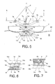
- Figures 1 to 4 illustrate a first embodiment of the active pendulum energy generator, comprising a support structure -1- assembled in a floating body -2- that can float in a water mass -M- heeling in response to waves -W-. It further comprises a pendulum -3- suspended by an arm -4- in a point of oscillation -5- in the upper part of the support structure -1- and capable of generating kinetic energy, as well as an electricity generating device -6- driven by the kinetic energy generated by the oscillations of the pendulum -3-.
- the pendulum -3- is attached to the arm -4- by means of a plurality of ties-4'- and is designed to oscillate back and forth, passing through a vertical position, between end positions in response to heel movements of the floating body -2- caused by the waves -W-.
- the pendulum energy generator also comprises a plurality of electricity generating devices -6- arranged in peripheral positions with respect to the end positions reached by the pendulum -3- when oscillating back and forth, and a transmission system to transmit the kinetic energy generated by the pendulum -3- to the electricity generating devices -6-.
- the transmission system comprises a plurality of drive arms -18- each coupled to one of the electricity generating devices -6-.
- Each drive arm -18- comprises a free end -18a-and an opposite end part -18b- coupled to the corresponding electricity generating device -6- and is movable between an extended position and a retracted position such that its movement between said positions drives the electricity generating device -6- to which it is coupled.
- the pendulum -3- is arranged between the free ends -18a- of the drive arms -18- such that when it oscillates to one of said end positions, it pushes at least one of the drive arms -18- towards its retracted position.
- the retaining system comprises a retaining rib -19- emerging from the lower surface of the pendulum -3- as well as a plurality of retaining mechanisms -20- each arranged in a radial position in correspondence with one of the drive arms -18-.
- Each retaining mechanism -20- comprises a retaining flange -20a- movable between a retaining position in which it protrudes and engages the retaining rib -19- while the pendulum -3- is located in its corresponding end position, and a release position in which it is retracted to release the pendulum -3- when the floating body -2- has passed the corresponding predetermined maximum heel position.
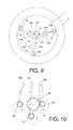
- said generator also comprises a support structure -1- assembled in a floating body -2- having a circular cross section that can float in a water mass -M-heeling in response to waves -W-.
- a ballast mass -25- extending completely or partially around the entire perimeter of the float is located in the upper part of the floating body - 2-.
- the generator further comprises a pendulum -3- suspended by an arm -4- in a point of oscillation -5- in the upper part of the support structure -1- and capable of generating kinetic energy, as well as an electricity generating device -6- driven by the oscillations of the pendulum -3-.
- the pendulum -3- is also designed to oscillate back and forth, passing through a vertical position -V-, between end positions in response to heel movements of the floating body -2- caused by the waves -W-.
- this second embodiment is capable of retaining the pendulum -3- alternately in each of said end positions until the floating body -2- has reached respective predetermined maximum heel positions -M1, M2- in response to the waves -W-, in which the respective end position in which the pendulum -3- is retained is located in a horizontal plane -H1- that is higher than the horizontal plane -H2, H3- of another end position, and to release the pendulum -3- so that it moves, passing through said vertical position -V-, towards another end position when the floating body -2- has passed the corresponding predetermined maximum heel position -M1, M2-.
- the electricity generating device -6- is housed in the floating body -2- under the pendulum -3- and is connected to a transmission system to transmit the kinetic energy generated by the pendulum -3- to the electricity generating device -6-.
- the transmission system comprises a gear system -8a, 8b, 8c; 9- connected to a drive shaft -6a- of the electricity generating device -6-, three drive cables -10a, 10b, 10c- each connected at its first end to the pendulum -3- and at its second end to said gear system -8a, 8b, 8c, 9-; and three reversing pulleys -11a, 11 b, 11c- peripherally assembled in the lower part of the support structure -1- in respective peripheral positions -1 a, 1b, 1 c- equiangular to one another, each of the reversing pulleys -11 a, 11 b, 11c- guiding one of the drive cables -10a, 10b, 10c- in its trajectory from the pendulum -3- towards the gear system -8a, 8b, 8c; 9-.
- the reversing pulleys -11a, 11 b, 11c- are assembled equiangular to one another at 120o angles.
- the retaining system further comprises respective peripheral blocking elements -7a, 7b, 7c- that can be connected to the reversing pulleys -11a, 11 b, 11 c- to block at least the reversing pulley -11a, 11 b, 11c- closest to the pendulum -3- when it is located in its end position in said higher horizontal plane -H1-, and to release the reversing pulleys -11 a, 11 b, 11 c- when the floating body -2- has passed the corresponding predetermined maximum heel position -M1, M2-, as well as three guide pulleys -12a, 12b, 12c- assembled in an equiangular manner in an area -14- surrounding the vertical of the pendulum -3- and respectively guiding one of the drive cables -10a, 10b, 10c- in its trajectory from the corresponding
- Each of the reversing pulleys -11a, 11 b, 11c- can be blocked by a central blocking element -15a, 15b, 15c- that can be connected to the reversing pulley -11a, 11 b, 11c-blocking the reversing pulley -11 a, 11 b, 11c- through which the drive cable -10a, 10b, 10c- passes which in turn passes through the reversing pulley -11a, 11 b, 11c- closest to the pendulum -3- when it is located in its end position in said higher horizontal plane -H1-, and releases the reversing pulley -11a, 11 b, 11c- when the floating body -2- has passed the corresponding predetermined maximum heel position -M1, M2-.
- the gear system -8a, 8b, 8c; 9- comprises a plurality of input pulleys -13a, 13b, 13c- provided with respective input pinions -8a, 8b, 8c-, each input pulley -13a, 13b, 13c- being connected to the second end of one of the drive cables -10a, 10b, 10c-.
- the input pinions -8a, 8b, 8c- can independently engage a gear ring -9- assembled in the drive shaft -6a- of the electricity generating device -6-.
- Respective lower blocking elements -16a, 16b, 16c- that can be connected to the input pulleys -13a, 13b, 13c- to block at least the input pulley -13a, 13b, 13c- through which the drive cable -10a, 10b, 10c- passes which in turn passes through the reversing pulley -11a, 11 b, 11c- closest to the pendulum -3- when it is located in its end position in said higher horizontal plane -H1-, and to release the input pulley -13a, 13b, 13c- when the floating body -2- has passed the corresponding predetermined maximum heel position -M1, M2- are also provided.
- Respective interlocking elements -17a, 17b, 17c- that can be interlocked with the input pinions -14a, 14b, 14c- of the respective input pulleys -13a, 13b, 13c- to block at least the input pinion -14a, 14b, 14c- of the input pulley -13a, 13b, 13c- through which the drive cable -10a, 10b, 10c- passes which in turn passes through the reversing pulley -11 a, 11 b, 11 c- closest to the pendulum -3- when it is located in its end position in said higher horizontal plane -H1-, and to release the input pinion -14a, 14b, 14c- when the floating body -2- has passed the corresponding predetermined maximum heel position -M1, M2- are likewise provided.
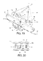
- the pendulum energy generator comprises, as in the first and second embodiments described above, a support structure -1- assembled in a floating body -2- that can float in a water mass -M-heeling in response to waves -W-. It further comprises a pendulum -3- suspended by an arm -4- in a point of oscillation -5- in the upper part of the support structure -1- and capable of generating kinetic energy, as well as an electricity generating device -6-driven by the oscillations of the pendulum -3-.
- the pendulum -3- is attached to the arm -4- by means of a plurality of ties-4'-, and is designed to oscillate back and forth, passing through a vertical position, between end positions in response to heel movements of the floating body -2- caused by the waves -W-.
- the electricity generating device -6- comprises an inductor -21-assembled in the pendulum -3- and an armature -22- assembled in the lower part of the support structure such that it extends under the pendulum -3- between the end positions between which the pendulum -3- oscillates.
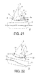
- the retaining system comprises a plurality of retaining cables -23- each connected at its first end to the pendulum -3- and at its second end to said gear system -8a, 8b, 8c, 9-, a plurality of retaining pulleys -24- assembled peripherally in the lower part of the support structure -1- in respective peripheral positions equiangular to one another, each retaining cable -23- passing through one of the retaining pulleys -24-, as well as respective peripheral blocking elements -7a, 7b- that can be connected to the retaining pulleys -11 a, 11b- to block at least the retaining pulley -24- closest to the pendulum -3-when it is located in its end position in said higher horizontal plane -H1-, and to release the retaining pulleys -24- when the floating body -2- has passed the corresponding predetermined maximum heel position -M1, M2-.
- Figures 21 and 22 show only two retaining cables -23-, two peripheral blocking elements -7a, 7b- and two retaining pulleys -24-, though it is implied that there can also be more of these elements, such as three of each for example, in which case the retaining pulleys -24- with their respective blocking elements, assembled equiangular to one another at 120o angles.
Landscapes
- Engineering & Computer Science (AREA)
- Chemical & Material Sciences (AREA)
- Combustion & Propulsion (AREA)
- Mechanical Engineering (AREA)
- General Engineering & Computer Science (AREA)
- Other Liquid Machine Or Engine Such As Wave Power Use (AREA)
- Connection Of Motors, Electrical Generators, Mechanical Devices, And The Like (AREA)
Applications Claiming Priority (1)
| Application Number | Priority Date | Filing Date | Title |
|---|---|---|---|
| ES201130766A ES2415239B1 (es) | 2011-05-12 | 2011-05-12 | generador de energía pendular activo |
Publications (2)
| Publication Number | Publication Date |
|---|---|
| EP2522848A2 true EP2522848A2 (de) | 2012-11-14 |
| EP2522848A3 EP2522848A3 (de) | 2013-04-03 |
Family
ID=46046079
Family Applications (1)
| Application Number | Title | Priority Date | Filing Date |
|---|---|---|---|
| EP12382159A Withdrawn EP2522848A3 (de) | 2011-05-12 | 2012-04-26 | Aktiver Pendelenergiegenerator |
Country Status (2)
| Country | Link |
|---|---|
| EP (1) | EP2522848A3 (de) |
| ES (1) | ES2415239B1 (de) |
Cited By (2)
| Publication number | Priority date | Publication date | Assignee | Title |
|---|---|---|---|---|
| RU2646523C2 (ru) * | 2016-07-13 | 2018-03-05 | ФГАОУ ВО "Севастопольский государственный университет" | Устройство для преобразования энергии волн |
| RU2655418C2 (ru) * | 2016-07-13 | 2018-05-28 | Федеральное государственное автономное образовательное учреждение высшего образования "Севастопольский государственный университет" | Устройство для преобразования энергии волн |
Citations (1)
| Publication number | Priority date | Publication date | Assignee | Title |
|---|---|---|---|---|
| ES2231041A1 (es) | 2002-01-29 | 2005-05-01 | Fco. Javier Jauregui Carro | Generador pendular. |
Family Cites Families (3)
| Publication number | Priority date | Publication date | Assignee | Title |
|---|---|---|---|---|
| FR2535403A2 (fr) * | 1982-03-16 | 1984-05-04 | Najman Max | Dispositif de production d'energie electrique a partir de la houle |
| US8701403B2 (en) * | 2005-11-07 | 2014-04-22 | Gwave Llc | System for producing energy through the action of waves |
| GB2473659B (en) * | 2009-09-19 | 2012-04-11 | Bruce Gregory | Dynamically tuned wave energy conversion system |
-
2011
- 2011-05-12 ES ES201130766A patent/ES2415239B1/es not_active Expired - Fee Related
-
2012
- 2012-04-26 EP EP12382159A patent/EP2522848A3/de not_active Withdrawn
Patent Citations (1)
| Publication number | Priority date | Publication date | Assignee | Title |
|---|---|---|---|---|
| ES2231041A1 (es) | 2002-01-29 | 2005-05-01 | Fco. Javier Jauregui Carro | Generador pendular. |
Cited By (2)
| Publication number | Priority date | Publication date | Assignee | Title |
|---|---|---|---|---|
| RU2646523C2 (ru) * | 2016-07-13 | 2018-03-05 | ФГАОУ ВО "Севастопольский государственный университет" | Устройство для преобразования энергии волн |
| RU2655418C2 (ru) * | 2016-07-13 | 2018-05-28 | Федеральное государственное автономное образовательное учреждение высшего образования "Севастопольский государственный университет" | Устройство для преобразования энергии волн |
Also Published As
| Publication number | Publication date |
|---|---|
| ES2415239B1 (es) | 2014-10-02 |
| EP2522848A3 (de) | 2013-04-03 |
| ES2415239A2 (es) | 2013-07-24 |
| ES2415239R1 (es) | 2013-12-16 |
Similar Documents
| Publication | Publication Date | Title |
|---|---|---|
| JP2010537099A (ja) | 波力発電システム | |
| EP3204635B1 (de) | Elektrischer generator und verfahren zur leistungserzeugung | |
| KR101604780B1 (ko) | 파력 발전 장치 | |
| US11053914B2 (en) | Electrical power generator for producing oscillating movement of a structure and converting oscillating movement into electrical energy | |
| KR101129527B1 (ko) | 풍력발전기 | |
| EP2461466B1 (de) | Generator mit Magnetgetriebe | |
| RU2613538C2 (ru) | Многонаправленный ветряной генератор кинетической энергии с повышенной эффективностью преобразования энергии ветра | |
| EP2522848A2 (de) | Aktiver Pendelenergiegenerator | |
| WO2010080045A1 (en) | Device for generating energy from the motion of sea waves | |
| KR101129525B1 (ko) | 풍력발전기 | |
| CN110192025A (zh) | 具有线缆支撑结构的风轮机 | |
| EP2693047B1 (de) | Windkraftanlage | |
| KR20100066027A (ko) | 격자형 파력발전 | |
| CN109236544B (zh) | 一种基于多桩柱聚波的点吸式波浪能发电装置 | |
| AU2021102244A4 (en) | Shore-based oscillating water column wave energy power generation device integrated with permeable wave elimination structure | |
| EP4073913B1 (de) | Stromgenerator | |
| CN111969830A (zh) | 一种震荡式海浪压力发电装置 | |
| KR20110015410A (ko) | 개량된 파동에너지 변환장치 | |
| KR20100069123A (ko) | 오뚝이 발전기 | |
| EP2986843B1 (de) | Anordnung zur nutzung von wellenenergie | |
| RU90848U1 (ru) | Гидроэлектростанция миронова-князева | |
| JP2015158134A (ja) | 発電機および増速機 | |
| CN113464621B (zh) | 一种基于滑轮组的动力装置 | |
| RU127132U1 (ru) | Устройство преобразования энергии волн водной поверхности в электрическую энергию | |
| RU2244850C2 (ru) | Способ преобразования энергии набегающего потока в электрическую энергию |
Legal Events
| Date | Code | Title | Description |
|---|---|---|---|
| PUAI | Public reference made under article 153(3) epc to a published international application that has entered the european phase |
Free format text: ORIGINAL CODE: 0009012 |
|
| AK | Designated contracting states |
Kind code of ref document: A2 Designated state(s): AL AT BE BG CH CY CZ DE DK EE ES FI FR GB GR HR HU IE IS IT LI LT LU LV MC MK MT NL NO PL PT RO RS SE SI SK SM TR |
|
| AX | Request for extension of the european patent |
Extension state: BA ME |
|
| PUAL | Search report despatched |
Free format text: ORIGINAL CODE: 0009013 |
|
| AK | Designated contracting states |
Kind code of ref document: A3 Designated state(s): AL AT BE BG CH CY CZ DE DK EE ES FI FR GB GR HR HU IE IS IT LI LT LU LV MC MK MT NL NO PL PT RO RS SE SI SK SM TR |
|
| AX | Request for extension of the european patent |
Extension state: BA ME |
|
| RIC1 | Information provided on ipc code assigned before grant |
Ipc: F03G 3/06 20060101ALI20130222BHEP Ipc: F03B 13/16 20060101AFI20130222BHEP |
|
| STAA | Information on the status of an ep patent application or granted ep patent |
Free format text: STATUS: THE APPLICATION IS DEEMED TO BE WITHDRAWN |
|
| 18D | Application deemed to be withdrawn |
Effective date: 20131005 |