EP2522280A1 - Medizinisches Instrument zum Greifen eines Objekts, insbesondere ein Nadelhalter - Google Patents
Medizinisches Instrument zum Greifen eines Objekts, insbesondere ein Nadelhalter Download PDFInfo
- Publication number
- EP2522280A1 EP2522280A1 EP12167507A EP12167507A EP2522280A1 EP 2522280 A1 EP2522280 A1 EP 2522280A1 EP 12167507 A EP12167507 A EP 12167507A EP 12167507 A EP12167507 A EP 12167507A EP 2522280 A1 EP2522280 A1 EP 2522280A1
- Authority
- EP
- European Patent Office
- Prior art keywords
- latching
- instrument
- elongated opening
- jaw part
- pivotable
- Prior art date
- Legal status (The legal status is an assumption and is not a legal conclusion. Google has not performed a legal analysis and makes no representation as to the accuracy of the status listed.)
- Granted
Links
Images


Classifications
-
- A—HUMAN NECESSITIES
- A61—MEDICAL OR VETERINARY SCIENCE; HYGIENE
- A61B—DIAGNOSIS; SURGERY; IDENTIFICATION
- A61B17/00—Surgical instruments, devices or methods, e.g. tourniquets
- A61B17/04—Surgical instruments, devices or methods, e.g. tourniquets for suturing wounds; Holders or packages for needles or suture materials
- A61B17/06—Needles ; Sutures; Needle-suture combinations; Holders or packages for needles or suture materials
- A61B17/062—Needle manipulators
-
- A—HUMAN NECESSITIES
- A61—MEDICAL OR VETERINARY SCIENCE; HYGIENE
- A61B—DIAGNOSIS; SURGERY; IDENTIFICATION
- A61B17/00—Surgical instruments, devices or methods, e.g. tourniquets
- A61B2017/00367—Details of actuation of instruments, e.g. relations between pushing buttons, or the like, and activation of the tool, working tip, or the like
- A61B2017/00407—Ratchet means
-
- A—HUMAN NECESSITIES
- A61—MEDICAL OR VETERINARY SCIENCE; HYGIENE
- A61B—DIAGNOSIS; SURGERY; IDENTIFICATION
- A61B17/00—Surgical instruments, devices or methods, e.g. tourniquets
- A61B17/28—Surgical forceps
- A61B17/29—Forceps for use in minimally invasive surgery
- A61B2017/2926—Details of heads or jaws
- A61B2017/2932—Transmission of forces to jaw members
- A61B2017/2933—Transmission of forces to jaw members camming or guiding means
- A61B2017/2934—Transmission of forces to jaw members camming or guiding means arcuate shaped guiding means
-
- A—HUMAN NECESSITIES
- A61—MEDICAL OR VETERINARY SCIENCE; HYGIENE
- A61B—DIAGNOSIS; SURGERY; IDENTIFICATION
- A61B17/00—Surgical instruments, devices or methods, e.g. tourniquets
- A61B17/28—Surgical forceps
- A61B17/29—Forceps for use in minimally invasive surgery
- A61B2017/2926—Details of heads or jaws
- A61B2017/2932—Transmission of forces to jaw members
- A61B2017/2933—Transmission of forces to jaw members camming or guiding means
- A61B2017/2936—Pins in guiding slots
-
- A—HUMAN NECESSITIES
- A61—MEDICAL OR VETERINARY SCIENCE; HYGIENE
- A61B—DIAGNOSIS; SURGERY; IDENTIFICATION
- A61B17/00—Surgical instruments, devices or methods, e.g. tourniquets
- A61B17/28—Surgical forceps
- A61B17/29—Forceps for use in minimally invasive surgery
- A61B2017/2946—Locking means
Definitions
- the present invention relates to a medical instrument for grasping an object, in particular a surgical needle holder, comprising an elongated shaft, two jaw parts arranged at a distal end of the shaft, at least one of the jaw parts being pivotable with respect to the other one of the jaw parts between a grasp state for grasping the object between the jaw parts and a release state for releasing the object, a handle arranged at a proximal end of the shaft and having at least one operating element for moving the at least one pivotable jaw part between the grasp state and the release state via an axially movable force transmission element running within the shaft and being operatively connected with the at least one operating element and with the at least one pivotable jaw part via a connection element, and further comprising a latching mechanism for immobilizing the at least one pivotable jaw part in the grasp state, wherein the latching mechanism comprises at least one latching element which is at least a part of the connection element, and which is operatively connected to the transmission element and the at least one pivotable jaw part, wherein the
- An instrument comprising a latching mechanism is known from EP 1 872 729 A1 .
- a latching element is realized by an arc-shaped lever, which is attached with one end of the arc at the force transmission element and with the other end of the arc attached to the at least one pivotable jaw part. While the location of a connection between the latching element and the transmission element is distal from the location of a connection of the latching element with the at least one pivotable jaw part in the release state, the location of the connection of the latching element with the transmission element is moved in proximal direction by pulling on the transmission element via the at least one operating element. This leads to a pivot of the at least one pivotable jaw part and results in a closing of the jaw parts.
- the two aforementioned locations connected via the flexible arc-shaped element i.e.
- the aforementioned latching mechanism has to be formed in that way that even with a small object, e.g. a needle of small diameter, the arc-shaped element has to be flexed at least a little in order to provide a working latching mechanism.
- the needle holding force and the maximum jaw opening angle are both sub-optimal. This is also due to the aforementioned needed capability of this instrument to accommodate small as well as larger objects.
- WO 2005/092216 A1 shows an instrument used for surgical laparoscopy.
- This instrument is designed such that a pivotable jaw part comprises a pin at the opposite end with respect to the cutting part of the jaws.
- This pin is slidingly received in a groove of an axially moveable element.
- the groove may comprise an elevation shift at its bottom. In this elevation shift the aforementioned pin may be temporarily received while the pin moves along this groove due to the axial movement of the element. This results in a temporarily lock of the pin without affecting the linear motion of the jaws relative to the handle actuation.
- This design comprises only one locked position as well. Also, due to the design with the short pin being slidingly arranged in a groove the locked position is not very stable, especially when stronger forces are applied in order to hold the aforementioned objects, like needles. Also, for the same reasons a twisting of the jaw parts in the direction of the pivot axis may occur due to the strong forces acting on the jaw parts when the aforementioned objects are grasped.
- the present invention is accordingly based on the object to improve the medical instruments of the kind mentioned before, such that the aforementioned drawbacks are avoided, in particular that the instrument is capable to accommodate objects of different sizes safely with the necessary holding force between the two jaw parts while simultaneously the strain in the parts is eliminated or at least reduced.
- the elongated opening is divided in several sections along its length, wherein the sections are formed by periodical projections on at least one of the opposing walls along the length of the elongated opening, each section forming a latching position, such that the at least one pivotable jaw part pivots stepwise from one stable latched position to another stable latched position, when the transmission element is moved axially, wherein the latching mechanism comprises at least three latching positions, preferably that the latching mechanism comprises three to eight and more preferably three to five latching positions.
- the instrument of the present invention does not comprise only one latching position, it comprises at least three, preferably three to eight and more preferably three to five.
- the at least one pivotable jaw part By such an arrangement, there are several latched positions of the at least one pivotable jaw part, each of them can be regarded as a stable state. Because of the plurality of the stable states resulting from this arrangement, an object, e.g. a surgical needle, can be accommodated and held by the two jaw parts fixedly in at least one of these stable states.
- a secure position for the at least one pivotable jaw part with respect to the other jaw part exists, in which the object can be held safely with the medical instrument of the present invention, independent of the size of the object to be held, provided the size is within a range capable to be held by the medical instrument of the present invention having itself limits based on the given size of the jaw parts.
- connection pin In order to achieve the grasp state, the connection pin just needs to move past the projections until it reaches the section that corresponds to the desired grasp state. Once the desired grasp state has been reached the connection pin rests against the previous projection in such a way as to maintain the grasp state. At the same time, a movement of the connection pin to the next section, i.e. by moving past the next projection, is blocked as the at least one pivotable jaw part is unable to pivot further due to the object between the jaw parts.
- this constructive design may be also described by wells or dents being comprised within the elongated opening. This means that one can also regard this separation into several sections being realized by at least one of the opposing walls comprising several wells or dents along the length of the elongated opening.
- one latched position forms the grasp state.
- the latched position forming the grasp state and a latched position forming the release state are achieved by the furthermost movement of the force transmission element in one respective axial direction when interacting with the object to grasp.
- This measure has the advantage that both necessary states, i.e. the grasp state and the release state, are achieved just by moving the force transmission element in one respective axial direction, i.e. in proximal or distal direction. This is preferably done by using the operating element. Accordingly, a user just needs to push or pull the operating element to one respective end, in order to achieve a grasp state or the release state. This is an easy way of operating the medical instrument of the present invention, as the latched positions responsible for grasping the object are reached automatically.
- connection element is arranged at the distal end of the force transmission element in that way that it undergoes the same axial movements as the force transmission element.
- connection element has the advantage that it is very easy to attach the connection element to the force transmission element. This can, for example, simply be done by measures known in the art, e.g. gluing, welding, screwing, or any other fit mechanisms, like latching mechanisms. This contributes to a simple design of the instrument of the present invention, while simultaneously achieving a versatile instrument in which this connection element can be replaced or exchanged, if necessary.
- the elongated opening is preferably arranged in that way, that a movement of the latching element by an axial movement of the transmission element results in a pivot of the at least one pivotable jaw part by movement of the connection pin within the elongated opening.
- connection pin for connecting the at least one pivotable jaw part with the latching element is basically just movable within the elongated opening and, accordingly, no flexible parts are needed for this latching mechanism in order to transfer the axial movement into a rotational movement.
- the device mentioned at the outset used for this is the flexible, arc-shaped lever.
- the elongated opening is arc-shaped.
- the latching element comprises two opposing faces and the elongated opening passes through the latching element from one face to the other face, wherein in a preferred embodiment the connection pin passes substantially through the elongated opening.
- the expression "passes substantially through” is to be understood in such a way that the pin may pass through and protrude from the opening on both sides, as well as that one end of the pin may also be flush with the face of the latching element or even that said end of the pin may also lie within the elongated opening, provided that a contact area between the connection pin and the surface within the elongated opening is such that an adequate force transmission to the at least one pivotable jaw part is possible for grasping the object.
- connection pin passing through the elongated opening of the latching element results in a stable arrangement and reliable transmission of force from the force transmission element to the at least one pivotable jaw part. It is thereby particularly preferred if the at least one pivotable jaw part is connected to the two opposing ends of the pin. While the connection pin can be connected to the at least one moveable jaw part at any point along the length of the jaw part, it is preferred if the connection between the pin and the jaw part is arranged at or near the proximal end of the at least one moveable jaw part, as such an arrangement will result in an even distribution of the force transmitted from the force transmission element to the jaws. As a consequence, a twisting of the jaw parts does not occur while grasping an object.
- connection pin can move from one to another section being latched in each.
- connection pin is the main component that operatively connects the at least one pivotable jaw part to the aforementioned latching element. Keeping the parts of a mechanism at a minimum like this has the further advantage of the whole device being easy to be cleaned.
- connection pin comprises a surface having a reduced coefficient of friction.
- reduced coefficient of friction refers to the latching element and the elongated opening with its opposing longer walls and shall be understood in comparison to the case wherein the material of the longer walls and the surface of the connection pin are both made of steel. Referring to the surface of the connection pin includes the cases wherein the whole connection pin is manufactured from this material as well as that the connection pin comprises a coating of such a material.
- connection pin shall be latched in the aforementioned latching positions, the movement from one latching position to another latching position, that is to say from one section to another section shall preferably be possible without the interference of friction while the connection pin moves within the elongated opening over at least one of the aforementioned opposing longer walls of the latter.
- This low friction surface may be present over the whole connection pin, a part of the connection pin that may be exposed to the outside or at least on that area of the connection pin that gets in contact with the opposing longer walls of the elongated opening.
- connection pin comprises a surface of Polytetrafluoroethylene.
- Such a surface of Polytetrafluoroethylene has the advantage that when applied at least to the areas that get in contact with the inside of the elongated opening, the friction may be significantly reduced.
- Polytetrafluoroethylene is resistant to the harsh conditions used in disinfection of a medical compound, like high temperatures in autoclaves and chemicals.
- Polytetrafluoroethylene provides a surface that is easy to clean and disinfect.
- the surface may be the result of at least partially coating the connection pin or of the connection pin being manufactured from Polytetrafluoroethylene.
- the reduced friction according to the present invention may also result if both, the surface of the connection pin and the surfaces within the elongated opening are covered with and/or manufactured from Polytetrafluoroethylene.
- the pin comprises a roller which is arranged between the opposing walls and which is moveable along the length of the elongated opening.
- roller has the advantage that the aforementioned strain of the connection pin is reduced, due to a certain flexibility of the roller. Further, the roller also shows the desired lower frictional characteristics. This reduction in friction has again the advantage that the movement of the roller within the elongated opening is more easy.
- each section accommodates the roller via form-fit, and the roller is able to move from one section to another.
- This measure has the advantage that the roller cannot accidentally slide along the elongated opening, thereby leading to an unwanted movement of the at least one pivotable jaw part in either direction.
- easy movement of the roller from one section to another section is still possible.
- the user just has to overcome the barrier given by the form-fit of the roller within the respective section.
- a latching mechanism comprising several latching positions is easily achieved.
- connection element is arranged in the shaft and comprises at least one sliding roller via which the connection element gets in contact with the shaft.
- connection element itself cannot get directly in contact with the inner wall of the shaft. This results in a highly reduced friction and, accordingly, in an easily movable connection element.
- the sliding roller itself shows low friction, as it rolls over the inside wall of the shaft.
- the roller is preferably arranged on the connection element via a pin.
- a proximal portion of the at least one pivotable jaw part is elastically deformable.
- This measure has the advantage that some strains that may even occur with the device of the present invention can be compensated by this elastically deformable proximal portion. This means that even by the application of a stronger force on the force transmission element, e.g. by a user or an operator, the forces acting on the elements taking part in the latching mechanism are reduced because of this flexibility.
- a medical instrument for grasping an object comprising an elongated shaft, two jaw parts arranged at a distal end of the shaft, at least one of the jaw parts being pivotable with respect to the other one of the jaw parts between a grasp state for grasping the object between the jaw parts and a release state for releasing the object, a handle arranged at a proximal end of the shaft and having at least one operating element for moving the at least one pivotable jaw part between the grasp state and the release state via an axially movable force transmission element running within the shaft and being operatively connected with the at least one operating element and with the at least one pivotable jaw part via a connection element, and further comprising a latching mechanism for immobilizing the at least one pivotable jaw part in the grasp state, wherein the latching mechanism comprises at least one latching element which is at least a part of the connection element, and which is operatively connected to the transmission element and the at least one pivotable jaw part
- the elongated opening comprises two opposing longer walls, and the sections are formed by periodical projections on at least one of the opposing walls along the length of the elongated opening.
- FIG. 10 An embodiment of a medical instrument according to the present invention is described hereinafter and is shown throughout Figs. 1 to 6 in its entirety by the reference numeral 10. Further embodiments of a medical instrument according to the present invention are also described with reference to Fig. 7 to 10 and shown hereinafter by the reference numerals 100 and 150.
- the medical instrument 10 comprises a shaft 12 having a distal part 14 and a proximal part 16.
- a handle 18 which itself comprises an operating element 20 which will be described later in more detail.
- the medical instrument 10 comprises two jaw parts 22 and 24.
- one of those jaw parts is a fixed jaw 22, wherein the other jaw part is a pivotable jaw 24.
- the pivotable jaw part 24 pivots around a pivot axis 26.
- the pivot axis 26 runs transversely through a central longitudinal axis 28 of the shaft 12.
- the shaft 12 is here just shown with its very distal part.
- This force transmission element 30 comprises a helical section 32, which is beneficial for the transmission of turning forces along the force transmission element 30 as it is described within EP 1 872 729 A1 , as mentioned at the outset.
- the force transmission element 30, here only shown in its distal end area, is at its proximal end connected to the aforementioned operating element 20.
- the force transmission element 30 is moved axially along the central longitudinal axis 28 in distal or proximal direction, as it is implied by a double arrow 34.
- the operating element 20 e.g. a push or pull movement
- the force transmission element 30 is moved axially along the central longitudinal axis 28 in distal or proximal direction, as it is implied by a double arrow 34.
- other mechanisms are possible with respect to the operating element 20, e.g. that a rotation of the operating element 20 leads to an axial movement of the force transmission element 30.
- connection element 36 At its distal end, the force transmission element 30 is connected to a connection element 36.
- the connection element 36 comprises in its distal end area a latching element 38, which will be described in more detail hereinafter, and a sliding roller 40.
- latching element 38 When reference is made to the distal end of the connection element 36 within the context of the present representations such reference may also be regarded as a reference to the latching element 38 in these embodiments and may be understood as such and vice-versa.
- the sliding roller 40 is arranged rotatably via a roller pin 42 on the connection element 36. As it projects from the connection element 36, the roller 40 prevents the contact of the connection element 36 with the inside wall of the shaft 12. Thereby, a frictional contact of the connection element 36 with the inner wall of the shaft 12 is avoided. Furthermore, the rotational arrangement of the roller 40 via a roller pin 42 avoids even a frictional interaction of the sliding roller 40 with the wall itself, so that the distal end of the force transmission element 30, i.e. the connection element 36, is able to easily slide back and forth with the directly connected force transmission element 30 as described before and as implied by double arrow 34.
- the sliding roller 40 is held via the roller pin 42 between two outer faces or sidewalls 44 and 44' of the connection element 36. This can be seen in more detail in the exploded view of Fig. 3 .
- the distal part 14 of the shaft 12 is connected via a connection ring 46 to the remaining part of shaft 12.
- a connection ring 46 to the remaining part of shaft 12.
- the distal part 14 might be movable with respect to the remaining part of shaft 12 around the central longitudinal axis 28.
- the embodiment comprising a helical section 32 of the force transmission element 30 is advantageous, as described earlier.
- connection element 36 further comprises an elongated opening 48.
- This elongated opening 48 is basically arc-shaped in the present embodiment. It passes through the connection element 36 or latching element 38 from one face 44 to the other, i.e. the opposite face 44', as can been seen in Fig. 3 .
- a roller 50 is accommodated in this elongated opening 48.
- the roller 50 itself is arranged via a connection pin 52 at a proximal end 54 of the at least one pivotable jaw 24.
- the proximal end 54 comprises two openings 56 and 56' for receiving the connection pin 52. This way, the connection pin 52 is connected to the at least one pivotable jaw part 24 with its opposing ends.
- the proximal end 54 further comprises a recess 58 in order to receive the distal end of the connection element 36, or, in particular, the latching element 38 in this proximal end 54.
- the connection pin 52 is oriented in that way that it runs transversely to the central longitudinal axis 28. Also, the connection pin 52 is arranged parallel to the pivot axis 26.
- the elongated opening 48 comprises two opposing longer walls 60 and 62.
- the longer wall 60 can be regarded as the distal wall, wherein the longer wall 62 is the proximal wall.
- the distal longer wall 60 comprises in this embodiment three projections 64, 64' and 64".
- the proximal longer wall 62 comprises two projections 66 and 66'. Therefore, these projections 64, 64', 64", 66 and 66' are arranged within the elongated opening.
- the roller 50 connects the pivotable jaw part 24 to the latching element 38 in that way that an axial movement of the connection element 36 and, consequently, of the latching element 38, which are a result from an axial movement of the force transmission element 30, results in a movement of the roller 50 within the elongated opening 48. As the roller 50 fits between the longer walls 60 and 62, the movement is only possible along the length of the elongated opening 48.
- Fig. 4a shows an arrangement wherein the jaw parts 22 and 24 are closed, comparable to the representation of Fig. 2 .
- the force transmission element 30 as well as the connection element 36 and, consequently, the latching element 38 are in their furthermost proximal position.
- the roller 50 is arranged within the elongated opening 48 between the distal end of this elongated opening 48 and the first projection 64" of the longer wall 60.
- the latching element 38 has to be moved distally. This is done by a distal movement of the connection element 36 via the force transmission element 30. This movement is implied by arrow 68 of Fig. 4a and can be done by an operator by pushing the operating element 20, for example.
- the roller 50 is able to overcome the barrier given by the projection 64". Accordingly, the roller 50 reaches a position as shown in Fig. 4b . In this position, the roller 50 is arranged between the projections 64" and 64'. The roller 50 now lies in a well 70. This well 70 is formed by the projections 64' and 64".
- the roller 50 is held in this well additionally by the projection 66' of the longer wall 62.
- This projection 66' is arranged opposite to the well 70.
- the roller 50 is held or latched in this position via form-fit.
- Such a form-fit occurs as well in the aforementioned most distal position of the roller 50 in the elongated opening 48 as well as in the following latched positions described in the context of Figs. 4c and 4d .
- roller 50 now is located between projections 64' and 64 in a well 70'.
- the aforementioned form-fit in this position is realized by the projection 66 of the longer wall 62.
- This projection 66 is arranged opposite from well 70'. The result is an even more enlarged opening of jaw parts 22 and 24 compared to the representation and state of Fig. 4b .
- the roller 50 overcame the barrier of the projection 64 of longer wall 60.
- the roller 50 thereby ends in the most proximal position in the elongated opening 48 of the embodiment of the instrument of the present invention shown here. Accordingly, the pivotable jaw part 24 shows in this state in Fig. 4d the largest possible opening for this embodiment.
- each of the shown positions in Fig. 4a through 4d forms a latched position according to the present invention.
- the medical instrument comprises four such latching positions.
- the latching element 38 by equipping the latching element 38 with more or fewer projections 64 and 66, alternate numbers of latching positions are possible and easy to achieve.
- Figs. 4a to 4d Although the mechanism shown throughout Figs. 4a to 4d is described in the context of an opening of the jaw parts 22 and 24, i.e. a pivot of the pivotable jaw part 24, the same mechanism works in the opposite direction, meaning for a closing of the jaw parts 22 and 24. Therefore, the force transmission element 30 has to be moved in the proximal direction. This is indicated by arrow 72 in Fig. 4d . This can, for example, be done by an operator by pulling on operating element 20.
- the closing procedure works apparently just opposite to the opening procedure, thereby overcoming the aforementioned barriers of the projections 64, 64' and 64" basically in the opposite direction.
- a large needle 74 is grasped by the jaw parts 22 and 24. This is achieved by arranging the needle 74 between the jaw parts 22 and 24 and pulling of the force transmission element 30, e.g. via the operating element 20, by an operator. Pulling of the force transmission element 30 results in a proximal movement of the force transmission element 30 and, accordingly, of the connection element 36 comprising the latching element 38. Thereby, with reference to Fig. 4d , the roller 50 is able to overcome the barrier of the projection 64 and, accordingly, moves distal within the elongated opening 48 into well 70', i.e. between projections 64 and 64'.
- Fig. 6 shows that in such an example the roller 50 may move within the elongated opening 48 also over the second projection 64', starting from the opening state of Fig. 4d . This results in a position of the roller 50 within well 70 and in between of the projections 64' and 64".
- roller 50 also stays as well in this latched position.
- This latching position is, in this case, formed by the well 70 and further by the projections 64' and 64".
- this grasping force for the objects here the needles 74 and 78, which stays nearly the same as already mentioned, allows the grasp of the needles to be optimal, independent of the needles' size.
- the proximal portion 54 of the pivotable jaw part 24 is equipped with a certain flexibility in one embodiment of the present invention. Thereby, an accidentally and unwanted stronger force applied to the force transmission element 30 is able to be compensated by this flexible proximal part 54 of the jaw part 24. This avoids the damaging of the parts of the latching mechanism 38.
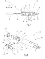
- the medical instrument 100 is almost identical to the medical instrument 10 as described before. In the following description and the drawings, the parts identical to that parts as described in the context of the medical instrument 10 are designated by the same reference signs.
- the medical instrument 100 will be described in the following by reference to Figs. 7 and 8 showing a distal end 104 of this medical instrument 100.
- the parts of the medical instrument 100 not shown in Figs. 7 and 8 shall be considered as identical to the respective parts in the medical instrument 10.
- connection pin 52 comprises the roller 50 in order to reduce the friction when the connection pin 52 moves through the elongated opening 48 the connection pin 52 is received directly within the elongated opening 48 in the medical instrument 100.
- roller 50 present in the description within the context of Figs. 4a to 6 was merely used by way of example. Accordingly, all the descriptions and explanations made within the context of Figs.
- connection pin 52 is accommodated within the elongated opening 48 and interacts in the described way with the projections 64, 64', 64", 66 and 66'. Therefore, the connection pin 52 of this embodiment is designed to be received in an optimal way for the desired sliding function.
- connection pin 52 allows for an easy cleaning of the whole device. Further, it simplifies the construction.
- connection pin 52 may comprise a surface having a reduced coefficient of friction with the material of the opposing walls 60 or 62. Such a surface may result from a low friction coating 106.
- This low friction coating 106 may cover the whole connection pin 52 as shown here or may just be applied to the areas necessary in order to reduce the friction between the connection pin 52 and the elongated opening 48 with its walls 60 and 62.
- PTFE Polytetrafluoroethylene
- connection pin 52 is made in this context with a low friction coating 106 it goes without mentioning that it is also possible to provide the same medical instruments without such a coating on the connection pin 52. Further, providing a connection pin 52 that is made of a material providing a reduced coefficient of friction like PTFE lies also within the scope of the present invention.
- the medical instrument 150 will now be described by reference to Figs. 9 and 10 .
- this medical instrument 150 is in most parts identical to the medical instrument 10 and only differs in a distal end 154 and the design of the pivotable jaw part 160 which will be described in the following.
- the parts not shown in Figs. 9 and 10 shall be considered as identical to the medical instrument 10. Further, identical parts with respect to the medical instrument 10 and 100 will be described and designated by the same reference signs.
- the medical instrument 150 comprises the same latching mechanism as the medical instrument 100.
- a connection pin 164 is arranged moveably directly within the elongated opening 48.
- no roller 50 is used in the embodiment of the medical instrument 150.
- all the explanations with respect to connection pin 52 made within the context of Figs. 7 and 8 describing the function of the latching mechanism are also valid for the medical instrument 150.
- the medical instrument 150 differs from the aforementioned medical instruments 10 and 100 in the pivotable jaw part 160. Instead of comprising two openings 56 and 56' at its proximal end 162 the jaw part 160 comprises a connection pin 164 directly attached to it.
- This connection pin 164 can be designed as the connection pin 52. This means, that the connection pin 164 may as well comprise a low friction coating 106.
- a further difference of the medical instrument 150 to the medical instrument 10 is that the medical instrument 150 does not comprise the sliding roller 40 arranged at a connection element 156.
- connection element 156 may slide within the shaft 12 of the medical instrument 150 directly.
- connection element 156 In order to provide a reduced friction of the connection element 156 of the medical instrument 150, the connection element 156 comprises a low friction coating 158. Thereby, the coefficient of friction with the inner wall of the shaft 12 is reduced. This provides an alternative to the sliding roller 40 of the medical instruments 10 or 100.
- the low friction coating may be realized by a Polytetrafluoroethylene coating.
- This kind of coating has the same advantages as mentioned before, i.e. that the friction is reduced as desired and that cleaning and sterilizing are possible under the conditions regularly used for medical instruments.
- connection element 156 Apart from using just a low friction coating 158, it is also possible that a small element of a low friction material is attached to the connection element 156 replacing the part of the connection element 156 which comprises the low friction coating 158. Further, the whole connection element 156 may be made out of such a low friction material. In all the mentioned cases, the connection element 156 comprises a surface having a reduced coefficient of friction.
- the aforementioned low friction materials can also be Polytetrafluoroethylene.
Landscapes
- Health & Medical Sciences (AREA)
- Life Sciences & Earth Sciences (AREA)
- Surgery (AREA)
- Heart & Thoracic Surgery (AREA)
- Engineering & Computer Science (AREA)
- Biomedical Technology (AREA)
- Nuclear Medicine, Radiotherapy & Molecular Imaging (AREA)
- Medical Informatics (AREA)
- Molecular Biology (AREA)
- Animal Behavior & Ethology (AREA)
- General Health & Medical Sciences (AREA)
- Public Health (AREA)
- Veterinary Medicine (AREA)
- Surgical Instruments (AREA)
Priority Applications (1)
| Application Number | Priority Date | Filing Date | Title |
|---|---|---|---|
| EP12167507.8A EP2522280B1 (de) | 2011-05-11 | 2012-05-10 | Medizinisches Instrument zum Greifen eines Objekts, insbesondere ein Nadelhalter |
Applications Claiming Priority (2)
| Application Number | Priority Date | Filing Date | Title |
|---|---|---|---|
| EP11165696 | 2011-05-11 | ||
| EP12167507.8A EP2522280B1 (de) | 2011-05-11 | 2012-05-10 | Medizinisches Instrument zum Greifen eines Objekts, insbesondere ein Nadelhalter |
Publications (2)
| Publication Number | Publication Date |
|---|---|
| EP2522280A1 true EP2522280A1 (de) | 2012-11-14 |
| EP2522280B1 EP2522280B1 (de) | 2016-03-02 |
Family
ID=46026736
Family Applications (1)
| Application Number | Title | Priority Date | Filing Date |
|---|---|---|---|
| EP12167507.8A Not-in-force EP2522280B1 (de) | 2011-05-11 | 2012-05-10 | Medizinisches Instrument zum Greifen eines Objekts, insbesondere ein Nadelhalter |
Country Status (2)
| Country | Link |
|---|---|
| US (1) | US8882799B2 (de) |
| EP (1) | EP2522280B1 (de) |
Cited By (2)
| Publication number | Priority date | Publication date | Assignee | Title |
|---|---|---|---|---|
| EP3213700A1 (de) | 2016-03-01 | 2017-09-06 | Karl Storz GmbH & Co. KG | Medizinisches instrument |
| EP3373831A4 (de) * | 2015-11-13 | 2019-07-03 | Intuitive Surgical Operations Inc. | Push-pull-klammernahtgerät mit griff mit zwei freiheitsgraden |
Families Citing this family (7)
| Publication number | Priority date | Publication date | Assignee | Title |
|---|---|---|---|---|
| US10863988B2 (en) | 2017-11-29 | 2020-12-15 | Intuitive Surgical Operations, Inc. | Surgical instrument with lockout mechanism |
| WO2019106737A1 (ja) * | 2017-11-29 | 2019-06-06 | オリンパス株式会社 | 医療用把持具 |
| US11317962B2 (en) * | 2018-05-04 | 2022-05-03 | Ethicon Llc | Dual axle robotic end effector |
| US20190365458A1 (en) * | 2018-05-31 | 2019-12-05 | Intuitive Surgical Operations, Inc. | Surgical instruments having a jaw locking mechanism |
| CN113194846A (zh) | 2018-12-21 | 2021-07-30 | 直观外科手术操作公司 | 具有加强钉仓的外科手术器械 |
| WO2021152753A1 (ja) * | 2020-01-29 | 2021-08-05 | オリンパス株式会社 | 処置具、及び処置具の製造方法 |
| DE102020119462A1 (de) * | 2020-07-23 | 2022-01-27 | Karl Storz Se & Co. Kg | Medizinisches instrument |
Citations (5)
| Publication number | Priority date | Publication date | Assignee | Title |
|---|---|---|---|---|
| DE20001492U1 (de) * | 2000-01-27 | 2000-06-21 | Aesculap Ag & Co Kg | Chirurgisches Rohrschaftinstrument |
| WO2004032754A2 (en) * | 2002-10-04 | 2004-04-22 | Tyco Healthcare Group, Lp | Tool assembly for surgical stapling device |
| WO2005092216A1 (en) | 2004-02-27 | 2005-10-06 | Applied Medical Resources Corporation | System and method for actuating a laparoscopic surgical instrument |
| EP1872729A1 (de) | 2006-06-29 | 2008-01-02 | The University of Dundee | Medizinisches Instrument zum Greifen eines Objektes, insbesondere Nadelhalter |
| EP2392282A1 (de) * | 2010-06-02 | 2011-12-07 | Tyco Healthcare Group, LP | Vorrichtung zur Durchführung eines elektrochirurgischen Verfahrens |
Family Cites Families (6)
| Publication number | Priority date | Publication date | Assignee | Title |
|---|---|---|---|---|
| US5392789A (en) * | 1991-04-04 | 1995-02-28 | Symbiosis Corporation | Endoscopic scissors having scissor elements loosely engaged with a clevis |
| US5409498A (en) * | 1992-11-05 | 1995-04-25 | Ethicon, Inc. | Rotatable articulating endoscopic fastening instrument |
| US5626607A (en) * | 1995-04-03 | 1997-05-06 | Heartport, Inc. | Clamp assembly and method of use |
| US6270508B1 (en) * | 1998-10-26 | 2001-08-07 | Charles H. Klieman | End effector and instrument for endoscopic and general surgery needle control |
| US7628791B2 (en) * | 2005-08-19 | 2009-12-08 | Covidien Ag | Single action tissue sealer |
| US7648519B2 (en) * | 2006-09-13 | 2010-01-19 | Cambridge Endoscopic Devices, Inc. | Surgical instrument |
-
2012
- 2012-05-10 EP EP12167507.8A patent/EP2522280B1/de not_active Not-in-force
- 2012-05-11 US US13/469,441 patent/US8882799B2/en not_active Expired - Fee Related
Patent Citations (5)
| Publication number | Priority date | Publication date | Assignee | Title |
|---|---|---|---|---|
| DE20001492U1 (de) * | 2000-01-27 | 2000-06-21 | Aesculap Ag & Co Kg | Chirurgisches Rohrschaftinstrument |
| WO2004032754A2 (en) * | 2002-10-04 | 2004-04-22 | Tyco Healthcare Group, Lp | Tool assembly for surgical stapling device |
| WO2005092216A1 (en) | 2004-02-27 | 2005-10-06 | Applied Medical Resources Corporation | System and method for actuating a laparoscopic surgical instrument |
| EP1872729A1 (de) | 2006-06-29 | 2008-01-02 | The University of Dundee | Medizinisches Instrument zum Greifen eines Objektes, insbesondere Nadelhalter |
| EP2392282A1 (de) * | 2010-06-02 | 2011-12-07 | Tyco Healthcare Group, LP | Vorrichtung zur Durchführung eines elektrochirurgischen Verfahrens |
Cited By (5)
| Publication number | Priority date | Publication date | Assignee | Title |
|---|---|---|---|---|
| EP3373831A4 (de) * | 2015-11-13 | 2019-07-03 | Intuitive Surgical Operations Inc. | Push-pull-klammernahtgerät mit griff mit zwei freiheitsgraden |
| US10898189B2 (en) | 2015-11-13 | 2021-01-26 | Intuitive Surgical Operations, Inc. | Push-pull stapler with two degree of freedom wrist |
| EP3213700A1 (de) | 2016-03-01 | 2017-09-06 | Karl Storz GmbH & Co. KG | Medizinisches instrument |
| DE102016103640A1 (de) | 2016-03-01 | 2017-09-07 | Karl Storz Gmbh & Co. Kg | Medizinisches Instrument |
| US10342560B2 (en) | 2016-03-01 | 2019-07-09 | Karl Storz Se & Co. Kg | Medical instrument |
Also Published As
| Publication number | Publication date |
|---|---|
| EP2522280B1 (de) | 2016-03-02 |
| US8882799B2 (en) | 2014-11-11 |
| US20120289999A1 (en) | 2012-11-15 |
Similar Documents
| Publication | Publication Date | Title |
|---|---|---|
| EP2522280B1 (de) | Medizinisches Instrument zum Greifen eines Objekts, insbesondere ein Nadelhalter | |
| KR102449277B1 (ko) | 수술 기구 | |
| EP2140818B1 (de) | Medizinisches Instrument zum Greifen eines Objekts, insbesondere eines Nadelhalters | |
| US9526495B2 (en) | Articulation control for surgical instruments | |
| US8206408B2 (en) | Surgical instrument with a shaft having a sliding part | |
| ES2533342T3 (es) | Tenazas de montaje con triquete de retención liberable | |
| US20110046661A1 (en) | Surgical instrument which can be disassembled | |
| CN104349730A (zh) | 用于医疗的,特别是外科手术器械的工具夹与手柄 | |
| WO2017135252A1 (ja) | ハンド機構 | |
| US20160331396A1 (en) | Surgical handle for a tool having a tubular shift | |
| CN111601561A (zh) | 铰接式手术器械 | |
| EP2077094B1 (de) | Wellendrehvorrichtung | |
| CN111565656A (zh) | 铰接式手术器械 | |
| JP6449884B2 (ja) | インプラントに対して外科用ロッドを操作、位置決め及び固定するための外科用器具 | |
| EP2567667A1 (de) | Behandlungswerkzeug | |
| US20140155933A1 (en) | Medizinisches Instrument | |
| US9226795B2 (en) | Robot structure | |
| JP5511991B2 (ja) | 狭い開口を通して到達することができる中空室内に配置された対象物を観察しかつ/または処置するための装置 | |
| EP3232956B1 (de) | Minimalinvasiv-chirurgische kanüle | |
| US10272549B2 (en) | Hinged ratchet wrench | |
| FR2997286B1 (fr) | Poignee pour instrument de microchirurgie, et instrument equipe de ladite poignee | |
| CN109561906B (zh) | 处置器具 | |
| CN109788966B (zh) | 处置器具用旋转机构 | |
| CN114947998A (zh) | 用于机器人手术系统的器械 | |
| WO2012010869A1 (en) | Handle and surgical instrument |
Legal Events
| Date | Code | Title | Description |
|---|---|---|---|
| PUAI | Public reference made under article 153(3) epc to a published international application that has entered the european phase |
Free format text: ORIGINAL CODE: 0009012 |
|
| AK | Designated contracting states |
Kind code of ref document: A1 Designated state(s): AL AT BE BG CH CY CZ DE DK EE ES FI FR GB GR HR HU IE IS IT LI LT LU LV MC MK MT NL NO PL PT RO RS SE SI SK SM TR |
|
| AX | Request for extension of the european patent |
Extension state: BA ME |
|
| 17P | Request for examination filed |
Effective date: 20130503 |
|
| GRAP | Despatch of communication of intention to grant a patent |
Free format text: ORIGINAL CODE: EPIDOSNIGR1 |
|
| INTG | Intention to grant announced |
Effective date: 20151021 |
|
| GRAS | Grant fee paid |
Free format text: ORIGINAL CODE: EPIDOSNIGR3 |
|
| GRAA | (expected) grant |
Free format text: ORIGINAL CODE: 0009210 |
|
| AK | Designated contracting states |
Kind code of ref document: B1 Designated state(s): AL AT BE BG CH CY CZ DE DK EE ES FI FR GB GR HR HU IE IS IT LI LT LU LV MC MK MT NL NO PL PT RO RS SE SI SK SM TR |
|
| REG | Reference to a national code |
Ref country code: GB Ref legal event code: FG4D |
|
| REG | Reference to a national code |
Ref country code: AT Ref legal event code: REF Ref document number: 777414 Country of ref document: AT Kind code of ref document: T Effective date: 20160315 Ref country code: CH Ref legal event code: EP |
|
| REG | Reference to a national code |
Ref country code: IE Ref legal event code: FG4D |
|
| REG | Reference to a national code |
Ref country code: DE Ref legal event code: R096 Ref document number: 602012015104 Country of ref document: DE |
|
| REG | Reference to a national code |
Ref country code: FR Ref legal event code: PLFP Year of fee payment: 5 |
|
| REG | Reference to a national code |
Ref country code: NL Ref legal event code: MP Effective date: 20160302 |
|
| REG | Reference to a national code |
Ref country code: LT Ref legal event code: MG4D |
|
| REG | Reference to a national code |
Ref country code: AT Ref legal event code: MK05 Ref document number: 777414 Country of ref document: AT Kind code of ref document: T Effective date: 20160302 |
|
| PG25 | Lapsed in a contracting state [announced via postgrant information from national office to epo] |
Ref country code: HR Free format text: LAPSE BECAUSE OF FAILURE TO SUBMIT A TRANSLATION OF THE DESCRIPTION OR TO PAY THE FEE WITHIN THE PRESCRIBED TIME-LIMIT Effective date: 20160302 Ref country code: FI Free format text: LAPSE BECAUSE OF FAILURE TO SUBMIT A TRANSLATION OF THE DESCRIPTION OR TO PAY THE FEE WITHIN THE PRESCRIBED TIME-LIMIT Effective date: 20160302 Ref country code: GR Free format text: LAPSE BECAUSE OF FAILURE TO SUBMIT A TRANSLATION OF THE DESCRIPTION OR TO PAY THE FEE WITHIN THE PRESCRIBED TIME-LIMIT Effective date: 20160603 Ref country code: NO Free format text: LAPSE BECAUSE OF FAILURE TO SUBMIT A TRANSLATION OF THE DESCRIPTION OR TO PAY THE FEE WITHIN THE PRESCRIBED TIME-LIMIT Effective date: 20160602 Ref country code: ES Free format text: LAPSE BECAUSE OF FAILURE TO SUBMIT A TRANSLATION OF THE DESCRIPTION OR TO PAY THE FEE WITHIN THE PRESCRIBED TIME-LIMIT Effective date: 20160302 |
|
| PG25 | Lapsed in a contracting state [announced via postgrant information from national office to epo] |
Ref country code: BE Free format text: LAPSE BECAUSE OF NON-PAYMENT OF DUE FEES Effective date: 20160531 Ref country code: PL Free format text: LAPSE BECAUSE OF FAILURE TO SUBMIT A TRANSLATION OF THE DESCRIPTION OR TO PAY THE FEE WITHIN THE PRESCRIBED TIME-LIMIT Effective date: 20160302 Ref country code: AT Free format text: LAPSE BECAUSE OF FAILURE TO SUBMIT A TRANSLATION OF THE DESCRIPTION OR TO PAY THE FEE WITHIN THE PRESCRIBED TIME-LIMIT Effective date: 20160302 Ref country code: RS Free format text: LAPSE BECAUSE OF FAILURE TO SUBMIT A TRANSLATION OF THE DESCRIPTION OR TO PAY THE FEE WITHIN THE PRESCRIBED TIME-LIMIT Effective date: 20160302 Ref country code: SE Free format text: LAPSE BECAUSE OF FAILURE TO SUBMIT A TRANSLATION OF THE DESCRIPTION OR TO PAY THE FEE WITHIN THE PRESCRIBED TIME-LIMIT Effective date: 20160302 Ref country code: LT Free format text: LAPSE BECAUSE OF FAILURE TO SUBMIT A TRANSLATION OF THE DESCRIPTION OR TO PAY THE FEE WITHIN THE PRESCRIBED TIME-LIMIT Effective date: 20160302 Ref country code: NL Free format text: LAPSE BECAUSE OF FAILURE TO SUBMIT A TRANSLATION OF THE DESCRIPTION OR TO PAY THE FEE WITHIN THE PRESCRIBED TIME-LIMIT Effective date: 20160302 Ref country code: LV Free format text: LAPSE BECAUSE OF FAILURE TO SUBMIT A TRANSLATION OF THE DESCRIPTION OR TO PAY THE FEE WITHIN THE PRESCRIBED TIME-LIMIT Effective date: 20160302 |
|
| PG25 | Lapsed in a contracting state [announced via postgrant information from national office to epo] |
Ref country code: EE Free format text: LAPSE BECAUSE OF FAILURE TO SUBMIT A TRANSLATION OF THE DESCRIPTION OR TO PAY THE FEE WITHIN THE PRESCRIBED TIME-LIMIT Effective date: 20160302 Ref country code: IS Free format text: LAPSE BECAUSE OF FAILURE TO SUBMIT A TRANSLATION OF THE DESCRIPTION OR TO PAY THE FEE WITHIN THE PRESCRIBED TIME-LIMIT Effective date: 20160702 |
|
| PG25 | Lapsed in a contracting state [announced via postgrant information from national office to epo] |
Ref country code: RO Free format text: LAPSE BECAUSE OF FAILURE TO SUBMIT A TRANSLATION OF THE DESCRIPTION OR TO PAY THE FEE WITHIN THE PRESCRIBED TIME-LIMIT Effective date: 20160302 Ref country code: CZ Free format text: LAPSE BECAUSE OF FAILURE TO SUBMIT A TRANSLATION OF THE DESCRIPTION OR TO PAY THE FEE WITHIN THE PRESCRIBED TIME-LIMIT Effective date: 20160302 Ref country code: PT Free format text: LAPSE BECAUSE OF FAILURE TO SUBMIT A TRANSLATION OF THE DESCRIPTION OR TO PAY THE FEE WITHIN THE PRESCRIBED TIME-LIMIT Effective date: 20160704 Ref country code: SK Free format text: LAPSE BECAUSE OF FAILURE TO SUBMIT A TRANSLATION OF THE DESCRIPTION OR TO PAY THE FEE WITHIN THE PRESCRIBED TIME-LIMIT Effective date: 20160302 Ref country code: SM Free format text: LAPSE BECAUSE OF FAILURE TO SUBMIT A TRANSLATION OF THE DESCRIPTION OR TO PAY THE FEE WITHIN THE PRESCRIBED TIME-LIMIT Effective date: 20160302 |
|
| REG | Reference to a national code |
Ref country code: DE Ref legal event code: R097 Ref document number: 602012015104 Country of ref document: DE |
|
| PG25 | Lapsed in a contracting state [announced via postgrant information from national office to epo] |
Ref country code: LU Free format text: LAPSE BECAUSE OF FAILURE TO SUBMIT A TRANSLATION OF THE DESCRIPTION OR TO PAY THE FEE WITHIN THE PRESCRIBED TIME-LIMIT Effective date: 20160510 Ref country code: BE Free format text: LAPSE BECAUSE OF FAILURE TO SUBMIT A TRANSLATION OF THE DESCRIPTION OR TO PAY THE FEE WITHIN THE PRESCRIBED TIME-LIMIT Effective date: 20160302 |
|
| REG | Reference to a national code |
Ref country code: CH Ref legal event code: PL |
|
| PLBE | No opposition filed within time limit |
Free format text: ORIGINAL CODE: 0009261 |
|
| STAA | Information on the status of an ep patent application or granted ep patent |
Free format text: STATUS: NO OPPOSITION FILED WITHIN TIME LIMIT |
|
| PG25 | Lapsed in a contracting state [announced via postgrant information from national office to epo] |
Ref country code: CH Free format text: LAPSE BECAUSE OF NON-PAYMENT OF DUE FEES Effective date: 20160531 Ref country code: LI Free format text: LAPSE BECAUSE OF NON-PAYMENT OF DUE FEES Effective date: 20160531 Ref country code: DK Free format text: LAPSE BECAUSE OF FAILURE TO SUBMIT A TRANSLATION OF THE DESCRIPTION OR TO PAY THE FEE WITHIN THE PRESCRIBED TIME-LIMIT Effective date: 20160302 |
|
| 26N | No opposition filed |
Effective date: 20161205 |
|
| REG | Reference to a national code |
Ref country code: IE Ref legal event code: MM4A |
|
| PG25 | Lapsed in a contracting state [announced via postgrant information from national office to epo] |
Ref country code: SI Free format text: LAPSE BECAUSE OF FAILURE TO SUBMIT A TRANSLATION OF THE DESCRIPTION OR TO PAY THE FEE WITHIN THE PRESCRIBED TIME-LIMIT Effective date: 20160302 Ref country code: BG Free format text: LAPSE BECAUSE OF FAILURE TO SUBMIT A TRANSLATION OF THE DESCRIPTION OR TO PAY THE FEE WITHIN THE PRESCRIBED TIME-LIMIT Effective date: 20160602 |
|
| REG | Reference to a national code |
Ref country code: FR Ref legal event code: PLFP Year of fee payment: 6 |
|
| PG25 | Lapsed in a contracting state [announced via postgrant information from national office to epo] |
Ref country code: IE Free format text: LAPSE BECAUSE OF NON-PAYMENT OF DUE FEES Effective date: 20160510 |
|
| REG | Reference to a national code |
Ref country code: FR Ref legal event code: PLFP Year of fee payment: 7 |
|
| PG25 | Lapsed in a contracting state [announced via postgrant information from national office to epo] |
Ref country code: HU Free format text: LAPSE BECAUSE OF FAILURE TO SUBMIT A TRANSLATION OF THE DESCRIPTION OR TO PAY THE FEE WITHIN THE PRESCRIBED TIME-LIMIT; INVALID AB INITIO Effective date: 20120510 Ref country code: CY Free format text: LAPSE BECAUSE OF FAILURE TO SUBMIT A TRANSLATION OF THE DESCRIPTION OR TO PAY THE FEE WITHIN THE PRESCRIBED TIME-LIMIT Effective date: 20160302 |
|
| PG25 | Lapsed in a contracting state [announced via postgrant information from national office to epo] |
Ref country code: TR Free format text: LAPSE BECAUSE OF FAILURE TO SUBMIT A TRANSLATION OF THE DESCRIPTION OR TO PAY THE FEE WITHIN THE PRESCRIBED TIME-LIMIT Effective date: 20160302 Ref country code: MK Free format text: LAPSE BECAUSE OF FAILURE TO SUBMIT A TRANSLATION OF THE DESCRIPTION OR TO PAY THE FEE WITHIN THE PRESCRIBED TIME-LIMIT Effective date: 20160302 Ref country code: MC Free format text: LAPSE BECAUSE OF FAILURE TO SUBMIT A TRANSLATION OF THE DESCRIPTION OR TO PAY THE FEE WITHIN THE PRESCRIBED TIME-LIMIT Effective date: 20160302 Ref country code: MT Free format text: LAPSE BECAUSE OF NON-PAYMENT OF DUE FEES Effective date: 20160531 |
|
| PG25 | Lapsed in a contracting state [announced via postgrant information from national office to epo] |
Ref country code: AL Free format text: LAPSE BECAUSE OF FAILURE TO SUBMIT A TRANSLATION OF THE DESCRIPTION OR TO PAY THE FEE WITHIN THE PRESCRIBED TIME-LIMIT Effective date: 20160302 |
|
| PGFP | Annual fee paid to national office [announced via postgrant information from national office to epo] |
Ref country code: FR Payment date: 20200422 Year of fee payment: 9 Ref country code: DE Payment date: 20200421 Year of fee payment: 9 |
|
| PGFP | Annual fee paid to national office [announced via postgrant information from national office to epo] |
Ref country code: GB Payment date: 20200423 Year of fee payment: 9 Ref country code: IT Payment date: 20200421 Year of fee payment: 9 |
|
| REG | Reference to a national code |
Ref country code: DE Ref legal event code: R119 Ref document number: 602012015104 Country of ref document: DE |
|
| GBPC | Gb: european patent ceased through non-payment of renewal fee |
Effective date: 20210510 |
|
| PG25 | Lapsed in a contracting state [announced via postgrant information from national office to epo] |
Ref country code: GB Free format text: LAPSE BECAUSE OF NON-PAYMENT OF DUE FEES Effective date: 20210510 Ref country code: DE Free format text: LAPSE BECAUSE OF NON-PAYMENT OF DUE FEES Effective date: 20211201 |
|
| PG25 | Lapsed in a contracting state [announced via postgrant information from national office to epo] |
Ref country code: FR Free format text: LAPSE BECAUSE OF NON-PAYMENT OF DUE FEES Effective date: 20210531 |
|
| PG25 | Lapsed in a contracting state [announced via postgrant information from national office to epo] |
Ref country code: IT Free format text: LAPSE BECAUSE OF NON-PAYMENT OF DUE FEES Effective date: 20200510 |