EP2522253B1 - Table - Google Patents
Table Download PDFInfo
- Publication number
- EP2522253B1 EP2522253B1 EP12167259.6A EP12167259A EP2522253B1 EP 2522253 B1 EP2522253 B1 EP 2522253B1 EP 12167259 A EP12167259 A EP 12167259A EP 2522253 B1 EP2522253 B1 EP 2522253B1
- Authority
- EP
- European Patent Office
- Prior art keywords
- table top
- top parts
- locking
- plate parts
- hook
- Prior art date
- Legal status (The legal status is an assumption and is not a legal conclusion. Google has not performed a legal analysis and makes no representation as to the accuracy of the status listed.)
- Active
Links
- 230000002093 peripheral effect Effects 0.000 claims description 7
- 230000005540 biological transmission Effects 0.000 description 18
- 238000011161 development Methods 0.000 description 10
- 230000018109 developmental process Effects 0.000 description 10
- 230000006872 improvement Effects 0.000 description 6
- 230000008878 coupling Effects 0.000 description 4
- 238000010168 coupling process Methods 0.000 description 4
- 238000005859 coupling reaction Methods 0.000 description 4
- 230000009471 action Effects 0.000 description 3
- 230000008901 benefit Effects 0.000 description 2
- 230000006835 compression Effects 0.000 description 2
- 238000007906 compression Methods 0.000 description 2
- 238000004146 energy storage Methods 0.000 description 2
- 238000000034 method Methods 0.000 description 2
- 230000008569 process Effects 0.000 description 2
- 230000001360 synchronised effect Effects 0.000 description 2
- PENWAFASUFITRC-UHFFFAOYSA-N 2-(4-chlorophenyl)imidazo[2,1-a]isoquinoline Chemical compound C1=CC(Cl)=CC=C1C1=CN(C=CC=2C3=CC=CC=2)C3=N1 PENWAFASUFITRC-UHFFFAOYSA-N 0.000 description 1
- 230000001154 acute effect Effects 0.000 description 1
- 238000007792 addition Methods 0.000 description 1
- 238000013459 approach Methods 0.000 description 1
- 238000005452 bending Methods 0.000 description 1
- 238000013016 damping Methods 0.000 description 1
- 238000006073 displacement reaction Methods 0.000 description 1
- 230000000694 effects Effects 0.000 description 1
- 238000009434 installation Methods 0.000 description 1
- 239000000463 material Substances 0.000 description 1
- 239000002184 metal Substances 0.000 description 1
Images


Classifications
-
- A—HUMAN NECESSITIES
- A47—FURNITURE; DOMESTIC ARTICLES OR APPLIANCES; COFFEE MILLS; SPICE MILLS; SUCTION CLEANERS IN GENERAL
- A47B—TABLES; DESKS; OFFICE FURNITURE; CABINETS; DRAWERS; GENERAL DETAILS OF FURNITURE
- A47B3/00—Folding or stowable tables
- A47B3/08—Folding or stowable tables with legs pivoted to top or underframe
- A47B3/083—Folding or stowable tables with legs pivoted to top or underframe with foldable top leaves
- A47B3/087—Folding or stowable tables with legs pivoted to top or underframe with foldable top leaves with struts supporting the legs
Definitions
- the idea of the present invention is to provide a table which is foldable by pivoting two plate parts to be brought from a usable state into a space-saving stowed state.
- the two plate parts In the usable state of the table, the two plate parts occupy a utilization position, in which the plate parts are arranged substantially in one plane. This allows the plate parts form a table top for the table.
- the pivotability of the plate members is achieved by a pivotable coupling of the plate members with a connecting member. In the use situation of the plate parts to ensure that the plate parts do not unexpectedly move out of the use situation, or in other words that the table does not fold up unexpectedly by itself. This can be avoided by a locking device, which makes it possible to lock the plate parts in the use position with the connecting member.
- the locking device is formed in such a way that at least one of the plate parts engages on pivoting of the plate parts from the stowage position in the utilization position in a Vorverriegelungslage the plate members to the connecting member.
- This snapping prevents the plate parts from moving back into the stowage position.
- it can be prevented that the table folds in the direction of its stowed state, if one of the plate parts unintentionally, for example by putting a person on this, is acted upon with a force before the plate parts are locked in the use position with the connecting member.
- a first of the plate parts is pivotally coupled to the connecting member about a first axis.
- a second of the plate parts is pivotally coupled to the connecting member about a second axis.
- the first axis in this case runs essentially parallel to the first plate part and the second axis runs essentially parallel to the second plate part.
- the locking device is further designed such that the plate parts are inclined relative to each other in the Vorverriegelungslage.
- An operator who brings about pivoting of the plate parts from the stowed position to the utilization position can easily see with a naked eye in a table according to this embodiment Detect whether the plate parts are in the Vorverriegelungslage or in the use position.
- the plate parts, of which at least one is already engaged on the connecting component in the pre-locking position are not yet locked in the utilization position.
- the operator person is therefore reminded by the visible inclination of the plate parts that the plate parts should still be locked. This further increases the safety for the operator when using the table according to the invention.
- the locking device has at least one actuating element.
- the locking device is designed such that the actuating element can be brought into a latching position and into a locking position. In this case, after the latching on the connecting component by moving the actuating element from the latching position into the locking position, a transfer of the plate parts from the prelocking position into the utilization position can be effected. At the same time, the locking of the plate parts in the utilization position can be effected by this movement of the actuating element. In this way, the operator person can also recognize on the basis of the position of the actuating element, whether the plate parts are locked in the use position or not.
- the locking device is furthermore designed in such a way that the engagement of the at least one or both plate parts on the connecting component can be achieved by moving the actuating element from the latching position to the release position.
- the plate parts can also be moved from the Vorverriegelungslage back into the stowage position.
- a plurality of actuating elements are provided.
- the actuators are adjacent to the edge portions of both plate members which face each other in the use position.
- two actuating elements are provided on each of the two plate parts, which are arranged on different sides of the respective plate part, whereby the locking of the plate parts and the release of the lock can be made in a more comfortable way.
- the locking device has a shaft mounted on the one of the plate parts, wherein an eccentric is rotatably connected to the shaft and a portion of the hook surrounds the eccentric at least partially.
- the eccentric makes it possible, by turning the shaft, to pull the hook against the plate part, thereby causing the pivoting from the pre-locking position into the utilization position and the locking in the utilization position.
- the hook has an arcuate recess facing the eccentric.
- a peripheral surface of the eccentric is in this case provided with a projection which is designed such that it engages in the arcuate recess.
- the shaft is rotatably connected to the actuating element.
- the actuating element may in this case preferably be designed as a pivotable button. In this way, by pivoting the actuating element between the latching position and the locking position, between the latching position and the release position or vice versa, a rotational movement of the shaft and thus a rotational movement of the eccentric can be achieved.
- the locking device further comprises a rotatably connected to the shaft, non-circular cam.
- the cam is arranged on the shaft in such a way that, in the latching position, the cam is in contact with a wall element fixedly connected to the one of the plate parts. The cam can thereby form a stop for the rotational movement of the shaft.
- the cam and the actuating element are arranged on the shaft in such a way that the actuating element in the locking position is substantially parallel to the one of the plate parts, and that the actuating element in the latched position substantially perpendicular to the one of the plate parts is aligned. For an operator, this is even more clearly recognizable by the vertical orientation of the actuator when the plate members are not yet locked in the use position. In addition, this configuration be advantageous if actuators are provided on each of the plate parts.
- actuators can first be brought out of their locking position with one hand one by one, or with both hands at the same time, in the respective latching position.
- the plate parts are preferably still engaged on the connecting component. Only the transfer of the actuators in the release position allows the back swinging the plate parts in the stowage position.
- the described compression of the actuators to release advantageously allows substantially simultaneous release of both plate members. The fact that the release can be done with one hand, the operator also has the other hand free.
- a leg spring is provided, which is arranged and supported such that the leg spring is tensioned when the shaft is rotated by a deflection of the actuating element out of the engaged position.
- This causes the actuating element, if it is not in the locking position, is acted upon by a force which it spends in the engaged position.
- the energy store is arranged and configured such that the plate parts between the stowage position and the use position have an equilibrium position in which the edge portions of the plate parts are spaced apart to avoid pinching a finger of an operator, and that the application of an additional Force on at least one of the plate parts is required to transfer the plate parts from the equilibrium position in the utilization position.
- the additional force is preferably applied manually by the operator, the additional force to be applied being set in such a way that the operator can accomplish this without great effort. This can prevent unintentional jamming of the fingers between the edge portions of the plate members.
- the operation of the table is even safer, since the movement of the plate parts from the equilibrium position in the utilization situation in this development of the invention must be brought about specifically.
- the energy store has at least one gas spring, wherein a first end of the gas spring is coupled to one of the plate parts and a second end of the gas spring is coupled to the connecting member.
- gas springs have a small footprint, allowing them to be placed on the table to save space, without disturbing.
- the force caused by the gas pressure springs on the plate parts and the connecting member is precisely adjustable. As a result, the equilibrium position can advantageously be set exactly.
- the connecting member is formed as a transmission carrier.
- a first rod and a second rod are provided, wherein the first rod is pivotally coupled to the first support and the second rod is pivotally coupled to the second support.
- the first and the second rod are pivotally coupled to the transmission component designed as a transmission carrier. Pivoting movements of the first rod and the second rod with respect to the gear carrier are in this case by a arranged on the gear carrier gear, which preferably acts positively, coupled to each other. This allows a movement of the first support with respect to the first plate member are synchronized with a movement of the second support relative to the second plate member during the pivoting of the plate members from the stowage position to the utilization position. Deformations of the plate parts and the supports to each other can be avoided.
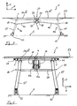
- Fig. 1 shows an embodiment of the table in a side view.
- the table 1 has a first plate part 2 a and a second plate part 2 b, which in the in Fig. 1 shown state of the table 1 are in a utilization position 2a "', 2b"' are.
- the plate parts 2a and 2b are arranged substantially in a first plane E1, which, like Fig. 1 shows, substantially parallel to a bottom 5 on which the table is supported runs.
- Fig. 1 also shows, run on lower sides of each of the plate parts 2a and 2b support members or trusses 3, which may be formed, for example, as metal profiles. These serve to stiffen and support the plate parts 2a and 2b.
- the support of the table 1 against the bottom 5 serve a first support 4a and a second support 4b.
- the supports 4a and 4b each have legs 15, and at the bottom 5 facing ends of the supports 4a and 4b rollers 12 are provided.
- the rollers 12 are pivotally connected to the supports 4a and 4b, whereby the table 1 is slidable in several directions and can be steered during the displacement.
- a connecting component 7 is arranged, wherein both the first plate part 2 a and the second plate part 2 b are pivotably coupled to the connecting component 7.
- gas pressure springs 11 are provided which, as will be described in more detail, are likewise pivotably coupled to the plate parts 2a and 2b and to the connection component 7.
- the gas springs 11 form an energy storage, the purpose of which will also be described in detail.
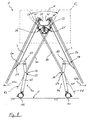
- the table 1 according to the embodiment of the invention is again shown in the state in which the plate parts 2a, 2b in the use position 2a "', 2b"' are.
- the connecting member 7 is formed at the table 1 as a gear carrier with two gear carrier parts 7 a and 7 b, wherein in Fig. 3 only a second of the gear carrier parts 7b is shown.
- the connecting member 7 carries a transmission 8 as a transmission carrier and forms a transmission housing for this.
- the transmission 8 has two gear segments 10a and 10b, as the enlargement of Fig. 4 even more clearly shows, wherein the gear segments 10a, 10b are engaged with each other by their teeth 9.
- the plate parts 2 a and 2 b of the table 1 are designed to be pivotable.
- the first plate part 2a is pivotally coupled to the connecting member 7 about a first axis 21, while the second plate part 2b is pivotally coupled to the connecting member 7 about a second axis 22.
- the first axis 21 is substantially parallel to the first plate portion 2a
- the second axis 22 is substantially parallel to the second plate portion 2b
- the two axes 21 and 22 extend in the embodiment shown also substantially parallel to each other.
- a first rod 6a and a second rod 6b are provided.
- One end of the first rod 6a is fixedly connected to the first gear segment 10a, while one end of the second rod 6b is fixedly connected to the second gear segment 10b.
- the first rod 6a is pivotally coupled to the first support 4a about a third axis 23, and the second rod 6b is pivotally coupled about a fourth axis 24 to the second support 4b.
- the two gear segments 10a and 10b are pivotally mounted about axes 25 and 26 on the connecting member 7 designed as a gear carrier. Thereby, the first rod 6a is pivotally coupled to the connecting member 7 about a fifth axis 25, while the second rod 6b is pivotally coupled to the connecting member 7 about a sixth axis 26.
- first plate portion 2a is pivotally coupled to first support 4a about a seventh axis 27, while second plate portion 2b is pivotally coupled to second support 4b about an eighth axis 28.
- the axes 21, 22, 23, 24, 25, 26, 27 and 28 extend in the embodiment shown preferably substantially parallel to each other and substantially parallel to the bottom 5.
- the axes 21 to 28 are shown projecting.
- the first axis 21 and the second axis 22 are relative to a plane of symmetry S, which is substantially perpendicular to the two plate parts 2a and 2b in the utilization position 2a "', 2b"' and in Fig. 3 also shown projecting, formed substantially symmetrical.
- the third axis 23 and the fourth axis 24 are arranged substantially symmetrically with respect to the plane of symmetry S.
- the fifth axis 25 and the sixth axis 26 are arranged substantially symmetrically with respect to S, and the seventh axis 27 and the eighth axis 28 are also arranged substantially symmetrically with respect to the plane of symmetry S.
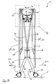
- the two plate parts 2 a and 2 b are thus relative to each other from in the FIGS. 1 to 3 shown utilization position 2a "', 2b"' in a stowage position 2a “, 2b” pivoted.
- the plate parts 2a and 2b run essentially parallel to each other and substantially perpendicular to the bottom 5.
- the table 1 is thus folded up to save space and can be rolled by means of rollers 12 which are arranged on the supports 4a and 4b, for example in a conference or meeting room to a place where it should be stored and does not bother.
- the two plate parts 2a and 2b can be pivoted relative to one another out of the stowage position 2a ", 2b" back into the utilization position 2a "', 2b"'.
- pull or push an operator as in Fig. 10 shown, preferably ends of the plate parts 2a and 2b in the direction of arrow 63a and 63b to the outside.
- the plate parts 2 a, 2 b pivot about the axes 21 and 22 with respect to the connecting member 7, as well as with respect to the supports 4 a and 4 b about the axes 27 and 28.
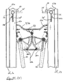
- the pivoting show the Fig. 8 and 6 , In this case, the first rod 6a and the second rod 6b also pivot about the third axis 23 and about the fourth axis 24 with respect to the first support 4a and the second support 4b, respectively.
- the rods 6a and 6b cross each other in the use and in the storage position and during the entire pivoting operation of the plate parts 2a, 2b between the use and storage position.
- 63b is added to the in Fig. 8 time reached a state in which the first axis 21, the fourth axis 24 and the sixth axis 26 lie in a second plane E2.
- the pivot axes take in the in Fig. 8 shown state a dead center.
- the Fig. 11 . 12 . 4 and 5 illustrate the pivotal coupling of the gas springs 11 with the connecting member 7 and the first plate member 2a and the second plate member 2b.
- Longitudinal axes of the gas springs 11 are denoted by the reference numeral 11a, pivotable attachment points of the gas springs 11 by the reference numeral 11b.
- the gas springs 11 are arranged in the manner, and their spring force is chosen such that the two plate parts 2a and 2b after passing over the in Fig. 8 shown dead center position, between the dead center and the utilization position 2a "', 2b"', but preferably well before reaching the utilization position 2a "', 2b”' assume an equilibrium position in which a balance of forces between the forces acting on the components of the table 1 weight forces on the one hand and the applied by the gas springs 11 restoring forces on the other hand is present.
- Edge portions 13a and 13b of the plate parts 2a and 2b are like the Fig. 4 . 9 and 11 make clear in the utilization position 2a "', 2b"' facing each other.
- the edge sections 13a, 13b form an only slight gap 20 in the use position 2a "', 2b"', whereby the plate parts 2a, 2b form parts of a table top of the table 1 which is substantially continuous except for the gap 20.
- the fact that the first and second plate parts 2a and 2b assume an equilibrium position before reaching the utilization position 2a "', 2b" under the effect of the gas pressure springs 11 avoids the pivoting process from the storage position 2a ", 2b" into the utilization position 2a "', 2b”' takes place at high speed and an operator person can pinch his fingers between the edge portions 13a, 13b painfully.
- the appropriately configured gas springs 11 cause the operator in the equilibrium position, not shown in the figures, to deliberately apply from above a force K on one or both of the plate parts 2a, 2b to move the plate parts 2a and 2b from the equilibrium position into the one Utilization situation 2a "', 2b"', see also the FIGS. 4 and 6 , In the equilibrium position, the edge portions 13a, 13b spaced sufficiently far apart so as not to act as a nip. This avoids unintentional trapping.
- the plate parts 2a and 2b are still slightly inclined by an angle ⁇ to each other. It is clearly visible and recognizable to an operator person that the plate parts 2a and 2b are located in the pre-locking position 2a ', 2b', thus not yet having reached the utilization position 2a "', 2b"'. Nevertheless, the plate parts 2a and 2b are already secured in the pre-locking position 2a ', 2b' against a backward movement in the direction of storage 2a ", 2b".
- the locking device 14 has actuating elements 31 on, see Fig. 4 ,
- the actuators 31 are arranged in the region of the edge portions 13a and 13b of the plate parts 2a and 2b.
- Each of the plate parts 2a, 2b is provided with two actuators 31, of which in Fig. 4 only one is visible at a time.
- the actuation elements 31 are additionally drawn in their locking position 31 "during pivoting or in the stowage position 2a", 2b "Preferably, the actuation elements 31 are in the stowage position 2a", 2b "and in their latching position 31 during pivoting '.
- the locking device 14 is thus configured such that when the plate parts 2 a and 2 b pivot to move to the pre-locking position 2 a ', 2 b' and finally reach the plate parts 2 a and 2 b engage the connecting member 7. Subsequently, by pivoting the actuating elements 31 from the latching position 31 'into the respective locking position 31 ", as in FIG Fig. 5 drawn, a locking of the plate parts 2a and 2b are effected on the connecting member 7.
- each of the actuators 31 may be formed as a pivotable button which is in the latched position 31 'substantially perpendicular to the respective plate member 2a and 2b, while the key in the locking position 31' substantially parallel to the respective plate member 2a, 2b runs.
- the two plate parts 2a and 2b can be pivoted out of the utilization position 2a"', 2b "'back into the equilibrium position and finally into the stowage position 2a", 2b ".
- connection component 7 moves in the vertical direction in the direction of the arrow 62 in FIG Fig. 6 moves, the supports 4a and 4b move apart in the direction of arrows 61a and 61b.
- the move Supports 4a and 4b in the transfer of the table from its use state in its stowed state in the direction of arrow 61a 'and 61b' toward each other, and the connecting member 7 rises in the direction 62 '.
- a housing 40 is provided adjacent to the respective edge section 13a or 13b.
- the housing 40 extends between the two trusses 3 below the respective plate member and is fixedly connected to the trusses 3 and the respective plate member.
- a shaft 32 extends, which is preferably designed as a polygonal shaft, for example, a hexagonal shaft.
- the shaft 32 is passed through the respective traverse 3 on both sides of the housing 40.
- an actuating element 31 rotatably connected to the shaft 32 each.
- the shaft 32 is preferably rotatably mounted in the region of its ends on the trusses 3 and / or the housing 40.
- Fig. 17 further shows that the locking device 14 has a hook 50.
- the hook 50 is also in the Fig. 4 (Detail XX), 9 and 11 recognizable.
- the connecting member 7 is provided with two projections 51.
- Each one of the projections 51 is arranged on the first transmission carrier part 7a or the second transmission carrier part 7b and, for example, formed integrally with the respective transmission carrier part. This is for example in Fig. 11 only one of the projections 51 visible.
- the hook 50 can be brought into positive engagement with the projection 51.
- the hook 50 has a ring portion 50a, through which the shaft 32 is passed. With the shaft 32, a two-part eccentric 33 is rotatably connected, wherein on one side of this hook 50, a first eccentric part 33a and on the other side of the hook 50, a second eccentric part 33b are arranged on the shaft.
- Each of the eccentric portions 33a and 33b is formed with two mutually off-axis portions.
- a peripheral surface 34a or 34b of the larger portion of the respective eccentric 33a and 33b is provided with a protrusion 35a, 35b, which extends radially outwardly.
- the smaller portion of the respective eccentric 33a, 33b forms an extension 36a and 36b, which projects over the peripheral surface 34a and 34b, respectively, a piece.
- a continuous hexagonal opening 39 extends.
- the ring portion 50 a of the hook 50 moreover two arcuate recesses 52 which face the eccentric 33 in the mounted state of the locking device, are open to the outside and each having a first end face 53 and a second end face 54.
- the section A'-A 'in Fig. 27 shows further that the hook 50 is formed substantially symmetrical, wherein on both sides of a plane of symmetry S1 each one of the arcuate recesses 52 is provided.
- the protrusions 35a, 35b engage in the respective arcuate recess 52 when the locking device 14 is assembled.
- the hook 50 can be deflected by rotation of the ring section 50a about the eccentric 33 even without rotation of the shaft 32 by a distance sufficient for the hook 50 to move out of the equilibrium position into the pre-locking position 2a 'during pivoting of the plate sections 2a and 2b. 2b 'engages with the projection 51, as shown in detail XX of Fig. 4 shown.
- the hook 50 preferably has a shape that allows a deflection of the hook 50 by sliding on the projection 51 and a subsequent engaging behind thereof. The hook 50 can thus engage behind the projection 51 in the latching position 31 'of the actuating element 31 and thereby prevent the plate parts 2a, 2b from moving back in the direction of the storage position 2a ", 2b".
- the hook 50 is pulled by the projections 35a and 35b upon rotation of the shaft 32 by passing through the arcuate recesses 52 in the housing 40 on the other hand further retraction of the hook 50 is effected by the peripheral surfaces of the extensions 36a, 36b at Rotate the shaft 32 with the bearing surfaces 72 of the thrust bearing 70 come into contact, supported on the bearing surfaces 72 and 32 shorten the distance of the hook 50 to the respective plate member even further by slight elastic bending of the shaft.
- the abutment 70 is held within the housing 40 by ribs 43 of the housing, which may be formed as a die-cast part.
- Fig. 17 further shows that the locking device 14 further comprises a leg spring 56 and a non-circular cam 55.
- the non-circular cam 55 is also rotatably connected to the shaft 32 and for this purpose preferably also has a continuous hexagonal opening.
- FIGS. 24 and 25 show that the cam 55 of the locking device 14 is preferably also disposed between ribs 43 of the associated housing 40.
- One leg of the leg spring 56 is supported on the cam 55, while the other leg is supported on the housing 40.
- the cam 55 and the leg spring 56 are arranged in such a way that upon rotation of the shaft 32 by a deflection of the actuating element 31 from the latched position 31 'out in the direction of one of the other two positions, ie the locking position 31 "or the release position 31st '', the leg spring 56 is stretched.
- the cam 55 and the shaft 32 are therefore acted upon by a restoring torque upon rotation of the actuating element 31 out of the latching position 31 '.
- Fig. 25 shows the cam in a state in which the actuating element 31 is disposed in the locking position 31 ''.
- the cam 55 assumes the position shown in FIG Fig. 24 shown position.
- the non-circular cam 55 bears against a wall element 41, for example a further rib of the housing 40.
- the present invention has been fully described above with reference to preferred embodiments, it is not limited thereto, but may be modified in a variety of ways. For example, it is not necessary to provide only one hook on each of the plate parts. There may also be several hooks, e.g. arranged side by side along the edge portions 13a, 13b are provided. Moreover, it is also not necessary to form the gear with a toothing, although this is advantageous. Instead, the transmission can also be designed as a chain transmission, a cable transmission or the like.
- the invention is not limited to use in office and conference furniture. Although the present invention is particularly advantageous there, it can equally be applied to table furniture for home, garden furniture or the like.
Description
Die vorliegende Erfindung betrifft einen Tisch.The present invention relates to a table.
Obwohl die vorliegende Erfindung im Zusammenhang mit Tischmöbeln unterschiedlicher Art, beispielsweise Tischen für Konferenzräume, Büros, Seminarzimmer oder dergleichen, aber auch im Zusammenhang mit Tischen für den Privathaushalt Anwendung finden kann, wird die vorliegende Erfindung und die ihr zugrunde liegende Problematik nachfolgend anhand eines großflächigen Konferenztisches näher erläutert.Although the present invention may find application in the context of table furniture of various kinds, such as tables for conference rooms, offices, seminar rooms or the like, but also in the context of tables for the private household, the present invention and the underlying problem will be below with reference to a large conference table explained in more detail.
Um Platz für das Ablegen einer großen Menge von Papieren, Zeichnungen oder anderen Arbeitsmaterialien zu bieten und um Besprechungen mit einer Vielzahl von Personen, die an diesem Tisch sitzen sollen, zu ermöglichen, sind Konferenztische oftmals mit relativ großflächigen Tischplatten ausgestattet. Um die Tischplatte gegen den Boden abzustützen, benötigt ein solcher Tisch dann meist auch ein entsprechend stabiles Untergestell.In order to accommodate a large amount of papers, drawings or other work materials and to facilitate meetings with a large number of people to sit at that table, conference tables are often equipped with relatively large table tops. In order to support the table top against the floor, such a table then usually requires a correspondingly stable base.
Gelegentlich kommt es vor, dass ein derartiger Konferenztisch an dem Ort, an dem er üblicherweise aufgestellt ist, aufgrund seiner Größe stört, beispielsweise, weil der zugehörige Konferenzraum in anderer Weise genutzt werden soll. In diesem Fall besteht der Wunsch, einen solchen großflächigen Konferenztisch möglichst mühelos und ohne größere Anstrengungen beiseiteschaffen und platzsparend verstauen zu können. Zudem besteht vielfach auch das Bedürfnis, den Konferenztisch für Besprechungen beispielsweise in unterschiedlichen Räumen leicht von einem Zimmer in ein anderes verbringen zu können.Occasionally, such a conference table in the place where it is usually placed, bothers because of its size, for example, because the associated conference room is to be used in other ways. In this case, there is a desire to create such a large-scale conference table as effortlessly and without much effort set aside and to save space. In addition, there is often the need, the conference table for For example, it is easy to spend meetings from one room to another in different rooms.
In der
Vor diesem Hintergrund liegt der vorliegenden Erfindung die Aufgabe zugrunde, einen verbesserten Tisch bereitzustellen, der sich schnell und mühelos aus einem Nutzungszustand in einen platzsparenden Zustand überführen lässt und der in ebenso müheloser Weise wieder in seinen benutzbaren Zustand zurückverwandelt werden kann. Für eine Bedienerperson sollen hierbei keine zusätzlichen Gefahrenquellen entstehen. Vor allem auch im Hinblick auf großflächige Tische soll erreicht werden, dass der Tisch sicher benutzt werden kann und nicht unerwartet in Bewegung gerät.Against this background, the present invention seeks to provide an improved table that can be quickly and easily transferred from a use state in a space-saving state and can be converted back to its usable state in an equally effortless manner. For an operator, no additional sources of danger should arise here. Especially with regard to large tables should be achieved that the table can be used safely and does not unexpectedly move.
Erfindungsgemäß wird diese Aufgabe durch einen Tisch mit den Merkmalen des Patentanspruchs 1 gelöst.According to the invention, this object is achieved by a table having the features of
Demgemäß ist ein Tisch mit zwei Plattenteilen vorgesehen, wobei die zwei Plattenteile relativ zueinander aus einer Verstaulage in eine Nutzungslage verschwenkbar sind. In der Nutzungslage sind die beiden Plattenteile im Wesentlichen in einer ersten Ebene angeordnet, und Randabschnitte beider Plattenteile sind in der Nutzungslage einander zugewandt. Zudem sind die Plattenteile mit einem Verbindungsbauteil jeweils um eine Achse schwenkbar gekoppelt. Es ist eine Verriegelungseiririchtung vorgesehen, mittels der die Plattenteile in der Nutzungslage mit dem Verbindungsbauteil verriegelbar sind. Die Verriegelungseinrichtung ist hierbei derart ausgebildet, dass die Verriegelungseinrichtung beim Verschwenken der Plattenteile aus ihrer Verstaulage in ihre Nutzungslage ein Einrasten zumindest eines der Plattenteile an dem Verbindungsbauteil bewirkt. Dieses Einrasten erfolgt, wenn sich die Plattenteile in einer Vorverriegelungslage befinden. Nach dem Einrasten sind die Plattenteile daran gehindert, sich in die Verstaulage zurückzubewegen.Accordingly, a table with two plate parts is provided, wherein the two plate parts are pivotable relative to each other from a stowage position to a use position. In the use position, the two plate parts are arranged substantially in a first plane, and edge portions of both plate parts are facing each other in the utilization situation. In addition, the plate parts are pivotally coupled to a connecting member about an axis. It is a Verriegelungseiririchtung provided by means of which the plate parts are locked in the use position with the connecting member. The locking device is in this case designed such that the locking device causes a locking of at least one of the plate parts on the connecting member during pivoting of the plate parts from their storage position in their use position. This latching takes place when the plate parts are in a pre-locking position. After snapping, the plate parts are prevented from moving back into the stowage position.
Die Idee der vorliegenden Erfindung besteht darin, einen Tisch bereitzustellen, welcher durch Verschwenken zweier Plattenteile faltbar ist, um von einem benutzbaren Zustand in einen platzsparenden Verstauzustand gebracht zu werden. In dem benutzbaren Zustand des Tisches nehmen die beiden Plattenteile eine Nutzungslage ein, in der die Plattenteile im Wesentlichen in einer Ebene angeordnet sind. Dadurch können die Plattenteile eine Tischplatte für den Tisch bilden. Die Schwenkbarkeit der Plattenteile wird durch eine schwenkbare Kopplung der Plattenteile mit einem Verbindungsbauteil erreicht. In der Nutzungslage der Plattenteile soll sichergestellt werden, dass sich die Plattenteile nicht unerwartet aus der Nutzungslage herausbewegen, oder anders gesagt, dass sich der Tisch nicht unerwartet von alleine zusammenfaltet. Dies kann durch eine Verriegelungseinrichtung vermieden werden, welche es ermöglicht, die Plattenteile in der Nutzungslage mit dem Verbindungsbauteil zu verriegeln. Um den Verschwenkvorgang der Plattenteile von der Verstaulage in die Nutzungslage noch sicherer und müheloser zu gestalten, ist die Verriegelungseinrichtung in der Weise ausgebildet, dass zumindest eines der Plattenteile beim Verschwenken der Plattenteile aus der Verstaulage in die Nutzungslage in einer Vorverriegelungslage der Plattenteile an dem Verbindungsbauteil einrastet. Dieses Einrasten verhindert, dass sich die Plattenteile wieder in die Verstaulage zurückbewegen. Damit kann beispielsweise verhindert werden, dass sich der Tisch in Richtung auf seinen Verstauzustand zusammenfaltet, wenn eines der Plattenteile unbeabsichtigt, z.B. durch Setzen einer Person auf dieses, mit einer Kraft beaufschlagt wird, bevor die Plattenteile in der Nutzungslage mit dem Verbindungsbauteil verriegelt sind. Auch in einem Fall, in dem das Verriegeln der Plattenteile versehentlich vergessen wird, ist ein gefahrloses Benutzen des Tisches nach dem Einrasten in der Vorverriegelungslage möglich. Es wird somit durch die Erfindung ein Tisch geschaffen, der platzsparend verstaut werden kann und auch dann noch sicher bedienbar ist, wenn er großflächig ausgeführt ist.The idea of the present invention is to provide a table which is foldable by pivoting two plate parts to be brought from a usable state into a space-saving stowed state. In the usable state of the table, the two plate parts occupy a utilization position, in which the plate parts are arranged substantially in one plane. This allows the plate parts form a table top for the table. The pivotability of the plate members is achieved by a pivotable coupling of the plate members with a connecting member. In the use situation of the plate parts to ensure that the plate parts do not unexpectedly move out of the use situation, or in other words that the table does not fold up unexpectedly by itself. This can be avoided by a locking device, which makes it possible to lock the plate parts in the use position with the connecting member. To make the pivoting of the plate parts of the stowage in the use situation even safer and easier the locking device is formed in such a way that at least one of the plate parts engages on pivoting of the plate parts from the stowage position in the utilization position in a Vorverriegelungslage the plate members to the connecting member. This snapping prevents the plate parts from moving back into the stowage position. Thus, for example, it can be prevented that the table folds in the direction of its stowed state, if one of the plate parts unintentionally, for example by putting a person on this, is acted upon with a force before the plate parts are locked in the use position with the connecting member. Even in a case in which the locking of the plate parts is accidentally forgotten, a safe use of the table after locking in the Vorverriegelungslage is possible. It is thus created by the invention, a table that can be stowed to save space and even then is safe to operate when it is designed over a large area.
Erfindungsgemäß weist der Tisch ferner einen Energiespeicher auf, welcher mit den Plattenteilen und dem Verbindungsbauteil derart gekoppelt ist, dass der Energiespeicher bei dem Verschwenken der Plattenteile von der Verstaulage in die Nutzungslage Energie aufnimmt. Auf diese Weise kann eine Kontrolle und eine Dämpfung der Verschwenkbewegung der Plattenteile von der Verstaulage in die Nutzungslage erzielt werden. Dadurch kann der erfindungsgemäße Tisch auf sichere und sanfte Art und Weise in seinen Nutzungszustand gebracht werden.According to the invention, the table further comprises an energy store, which is coupled to the plate parts and the connecting component in such a way that the energy store absorbs energy when pivoting the plate parts from the storage position into the utilization position. In this way, a control and a damping of the pivoting movement of the plate members can be achieved by the stowage in the utilization position. As a result, the table according to the invention can be brought into its use state in a safe and gentle manner.
Vorteilhafte Ausgestaltungen und Weiterbildungen ergeben sich aus den weiteren Unteransprüchen. Gemäß einer Ausgestaltung des erfindungsgemäßen Tisches ist die Verriegelungseinrichtung derart ausgebildet, dass sie beim Verschwenken der Plattenteile aus der Verstaulage in die Nutzungslage in der Vorverriegelungslage ein Einrasten beider Plattenteile an dem Verbindungsbauteil bewirkt. Somit sind vorteilhaft beide Plattenteile zuverlässig an einer Zurückbewegung in Richtung auf die Verstaulage gehindert.Advantageous embodiments and further developments emerge from the further subclaims. According to one embodiment of the table according to the invention, the locking device is designed such that it causes a latching of both plate parts on the connecting member during pivoting of the plate parts from the stowage position in the utilization position in the Vorverriegelungslage. Thus, advantageously, both plate parts are reliably prevented from moving back toward the stowage position.
Bei einer Ausgestaltung der Erfindung ist ein erstes der Plattenteile mit dem Verbindungsbauteil um eine erste Achse schwenkbar gekoppelt. Zudem ist bei dieser Ausgestaltung ein zweites der Plattenteile mit dem Verbindungsbauteil um eine zweite Achse schwenkbar gekoppelt. Die erste Achse verläuft hierbei im Wesentlichen parallel zu dem ersten Plattenteil und die zweite Achse verläuft im Wesentlichen parallel zu dem zweiten Plattenteil. Dies ermöglicht es beispielsweise, die Plattenteile aus einer Nutzungslage, in der die Plattenteile bevorzugt im Wesentlichen parallel zu einem Boden, auf dem der Tisch aufgestellt ist, verlaufen, in eine bezüglich des Bodens im Wesentlichen vertikale, aufrechte Verstaulage zu überführen. In der Verstaulage der Plattenteile ist der Tisch dann besonders wenig raumgreifend, wodurch Aufstellfläche gespart wird. Gerade bei großflächigen Konferenztischen ist dies vorteilhaft.In one embodiment of the invention, a first of the plate parts is pivotally coupled to the connecting member about a first axis. In addition, in this embodiment, a second of the plate parts is pivotally coupled to the connecting member about a second axis. The first axis in this case runs essentially parallel to the first plate part and the second axis runs essentially parallel to the second plate part. This makes it possible, for example, the plate parts from a utilization position in which the plate parts preferably extend substantially parallel to a floor on which the table is placed, in a respect to the Bodens essentially vertical, upright stowage to convict. In the stowage of the plate parts, the table is then very little space, which saves installation space. Especially with large conference tables, this is advantageous.
In einer weiteren Ausgestaltung verläuft die erste Achse im Wesentlichen parallel zu der zweiten Achse. Bevorzugt verlaufen die erste Achse und die zweite Achse auch im Wesentlichen parallel zu den Randabschnitten beider Plattenteile, die einander in der Nutzungslage zugewandt sind. Dadurch kann beispielsweise ein möglichst kurzer Spalt zwischen den Randabschnitten der beiden Plattenteile erzielt werden. Darüber hinaus ist der Tisch bei dieser Ausgestaltung besonders platzsparend, wenn sich die Plattenteile in der Verstaulage befinden.In a further embodiment, the first axis is substantially parallel to the second axis. Preferably, the first axis and the second axis are also substantially parallel to the edge portions of both plate parts, which face each other in the utilization position. As a result, for example, the shortest possible gap between the edge portions of the two plate parts can be achieved. In addition, the table is particularly space-saving in this embodiment, when the plate parts are in the stowed position.
Bei einer bevorzugten Ausgestaltung des erfindungsgemäßen Tisches ist die Verriegelungseinrichtung derart ausgebildet, dass die Vorverriegelungslage erreichbar ist, bevor die Plattenteile die Nutzungslage erreicht haben. Dadurch kann erzielt werden, dass beim Auseinanderfalten des Tisches die Vorverriegelungslage durch die Plattenteile zuverlässig eingenommen wird. Es kann auf diese Weise ferner vermieden werden, dass die Plattenteile an dem Verbindungsbauteil anstehen, bevor sie die Vorverriegelungslage erreichen.In a preferred embodiment of the inventive table, the locking device is designed such that the pre-locking position is reached before the plate parts have reached the utilization position. It can thereby be achieved that when unfolding the table, the Vorverriegelungslage is taken reliably by the plate members. It can be further avoided in this way that the plate parts are present at the connecting member before they reach the Vorverriegelungslage.
Gemäß einer weiteren Ausgestaltung ist die Verriegelungseinrichtung ferner derart ausgebildet, dass die Plattenteile in der Vorverriegelungslage relativ zueinander geneigt sind. Eine Bedienerperson, die ein Verschwenken der Plattenteile von der Verstaulage in die Nutzungslage herbeiführt, kann bei einem Tisch gemäß dieser Ausgestaltung leicht mit bloßem Auge erkennen, ob sich die Plattenteile in der Vorverriegelungslage oder in der Nutzungslage befinden. Dadurch wird für die Bedienerperson erkennbar, wenn die Plattenteile, von denen in der Vorverriegelungslage zumindest eines bereits an dem Verbindungsbauteil eingerastet ist, noch nicht in der Nutzungslage verriegelt sind. Die Bedienerperson wird also durch die sichtbare Neigung der Plattenteile daran erinnert, dass die Plattenteile noch verriegelt werden sollten. Dies erhöht die Sicherheit für die Bedienerperson bei der Benutzung des erfindungsgemäßen Tisches weiter.According to a further embodiment, the locking device is further designed such that the plate parts are inclined relative to each other in the Vorverriegelungslage. An operator who brings about pivoting of the plate parts from the stowed position to the utilization position can easily see with a naked eye in a table according to this embodiment Detect whether the plate parts are in the Vorverriegelungslage or in the use position. As a result, it becomes apparent to the operator person if the plate parts, of which at least one is already engaged on the connecting component in the pre-locking position, are not yet locked in the utilization position. The operator person is therefore reminded by the visible inclination of the plate parts that the plate parts should still be locked. This further increases the safety for the operator when using the table according to the invention.
Bei einer weiteren Verbesserung der Erfindung ist vorgesehen, dass die Verriegelungseinrichtung zumindest ein Betätigungselement aufweist. Gemäß dieser Verbesserung ist die Verriegelungseinrichtung derart ausgebildet, dass das Betätigungselement in eine Einraststellung und in eine Verriegelungsstellung bringbar ist. Hierbei kann nach dem Einrasten an dem Verbindungsbauteil durch ein Bewegen des Betätigungselements von der Einraststellung in die Verriegelungsstellung ein Überführen der Plattenteile von der Vorverriegelungslage in die Nutzungslage bewirkt werden. Zugleich ist durch diese Bewegung des Betätigungselements das Verriegeln der Plattenteile in der Nutzungslage bewirkbar. Auf diese Weise kann die Bedienerperson auch anhand der Stellung des Betätigungselements erkennen, ob die Plattenteile in der Nutzungslage verriegelt sind oder nicht.In a further improvement of the invention it is provided that the locking device has at least one actuating element. According to this improvement, the locking device is designed such that the actuating element can be brought into a latching position and into a locking position. In this case, after the latching on the connecting component by moving the actuating element from the latching position into the locking position, a transfer of the plate parts from the prelocking position into the utilization position can be effected. At the same time, the locking of the plate parts in the utilization position can be effected by this movement of the actuating element. In this way, the operator person can also recognize on the basis of the position of the actuating element, whether the plate parts are locked in the use position or not.
Gemäß einer weiteren Weiterentwicklung ist die Verriegelungseinrichtung derart ausgebildet, dass das Betätigungselement ferner in eine Lösestellung bringbar ist. Hierbei ist durch ein Bewegen des Betätigungselements von der Verriegelungsstellung über die Einraststellung in die Lösestellung die Verriegelung der Plattenteile lösbar. Dadurch kann der Tisch durch Verschwenken der Plattenteile von der Nutzungslage in die Verstaulage wieder in einen platzsparenden Verstauzustand gebracht werden.According to a further development of the locking device is designed such that the actuating element is further brought into a release position. In this case, by locking the actuating element from the locking position via the latching position into the release position, the locking of the plate parts can be released. This can make the table be brought by swiveling the plate parts of the utilization position in the stowage again in a space-saving stowage condition.
Bei einer weiteren Ausgestaltung des erfindungsgemäßen Tisches ist die Verriegelungseinrichtung darüber hinaus derart ausgebildet, dass durch ein Bewegen des Betätigungselements von der Einraststellung in die Lösestellung das Einrasten des zumindest einen oder beider Plattenteile an dem Verbindungsbauteil gelöst werden kann. Dadurch können die Plattenteile auch aus der Vorverriegelungslage wieder in die Verstaulage verbracht werden.In a further embodiment of the table according to the invention, the locking device is furthermore designed in such a way that the engagement of the at least one or both plate parts on the connecting component can be achieved by moving the actuating element from the latching position to the release position. As a result, the plate parts can also be moved from the Vorverriegelungslage back into the stowage position.
In einer weiteren Weiterentwicklung der Erfindung sind mehrere Betätigungselemente vorgesehen. Bevorzugt sind die Betätigungselemente den Randabschnitten beider Plattenteile, die in der Nutzungslage einander zugewandt sind, benachbart angeordnet. Besonders bevorzugt sind an jedem der beiden Plattenteile zwei Betätigungselemente vorgesehen, die an unterschiedlichen Seiten des jeweiligen Plattenteils angeordnet sind, wodurch das Verriegeln der Plattenteile und das Lösen der Verriegelung auf noch komfortablere Weise erfolgen können.In a further development of the invention, a plurality of actuating elements are provided. Preferably, the actuators are adjacent to the edge portions of both plate members which face each other in the use position. Particularly preferably, two actuating elements are provided on each of the two plate parts, which are arranged on different sides of the respective plate part, whereby the locking of the plate parts and the release of the lock can be made in a more comfortable way.
In einer Ausgestaltung der Erfindung weist die Verriegelungseinrichtung einen Haken auf. Der Haken ist hierbei an einem der Plattenteile bewegbar gelagert. Ferner weist das Verbindungsbauteil bei dieser Ausgestaltung einen Vorsprung auf, welcher derart angeordnet und ausgebildet ist, dass der Haken mit dem Vorsprung formschlüssig in Eingriff bringbar ist. Ein formschlüssiges Eingreifen eines Hakens in einen Vorsprung bewirkt ein besonders zuverlässiges Einrasten und Verriegeln der Plattenteile an dem Verbindungsbauteil.In one embodiment of the invention, the locking device has a hook. The hook is in this case movably mounted on one of the plate parts. Furthermore, in this embodiment, the connecting component has a projection, which is arranged and designed such that the hook can be brought into positive engagement with the projection. A positive engagement of a hook in a projection causes a particularly reliable engagement and locking of the plate members on the connecting member.
Gemäß einer Verbesserung ist der Haken derart gelagert, dass der Haken um einen Weg auslenkbar ist, welcher ausreichend ist, um den Haken beim Verschwenken der Plattenteile in die Vorverriegelungslage mit dem Vorsprung in Eingriff zu bringen, wenn sich das Betätigungselement in der Einraststellung befindet. Hierbei erfolgt das Einrasten an dem Verbindungsbauteil vorteilhaft automatisch, indem der Haken den Vorsprung hintergreift, ohne dass ein weiteres Zutun der Bedienerperson erforderlich wäre.According to an improvement, the hook is mounted such that the hook is deflectable by a distance which is sufficient to bring the hook during pivoting of the plate members in the Vorverriegelungslage with the projection into engagement when the actuating element is in the latched position. In this case, the latching takes place on the connecting component advantageously automatically by the hook engages behind the projection, without any further action of the operator person would be required.
Bei einer Weiterentwicklung der Erfindung weist die Verriegelungseinrichtung eine an dem einen der Plattenteile gelagerte Welle auf, wobei mit der Welle ein Exzenter drehfest verbunden ist und ein Abschnitt des Hakens den Exzenter zumindest teilweise umgreift. Der Exzenter ermöglicht es, durch ein Verdrehen der Welle den Haken an das Plattenteil heranzuziehen, und dadurch das Verschwenken von der Vorverriegelungslage in die Nutzungslage und das Verriegeln in der Nutzungslage zu bewirken.In a further development of the invention, the locking device has a shaft mounted on the one of the plate parts, wherein an eccentric is rotatably connected to the shaft and a portion of the hook surrounds the eccentric at least partially. The eccentric makes it possible, by turning the shaft, to pull the hook against the plate part, thereby causing the pivoting from the pre-locking position into the utilization position and the locking in the utilization position.
In einer weiteren Ausgestaltung weist der Haken eine dem Exzenter zugewandte bogenförmige Ausnehmung auf. Eine Umfangsfläche des Exzenters ist hierbei mit einer Erhebung versehen, welche derart ausgebildet ist, dass sie in die bogenförmige Ausnehmung eingreift. Beim Bewegen des Betätigungselements von der Einraststellung in die Verriegelungsstellung durchläuft hierbei die Erhebung die bogenförmige Ausnehmung von einer ersten Endfläche zu einer zweiten Endfläche der bogenförmigen Ausnehmung. Hierdurch besitzt der Exzenter bezüglich des Hakens zwei definierte Endstellungen. Ferner kann dadurch, dass die Erhebung in der Einraststellung an der ersten Endfläche vorzugsweise zur Anlage gelangt, durch die Einwirkung der Erhebung auf die erste Endfläche der bogenförmigen Ausnehmung der Haken bei einem weiteren Verdrehen des Exzenters, bevorzugt beim Bewegen des Betätigungselements von der Einraststellung in die Lösestellung, in der Weise ausgelenkt werden, dass der Haken und der Vorsprung außer Eingriff gebracht werden.In a further embodiment, the hook has an arcuate recess facing the eccentric. A peripheral surface of the eccentric is in this case provided with a projection which is designed such that it engages in the arcuate recess. When moving the actuating element from the latching position into the locking position, in this case the elevation passes through the arcuate recess from a first end surface to a second end surface of the arcuate recess. As a result, the eccentric with respect to the hook has two defined end positions. Furthermore, the fact that the elevation preferably comes into abutment in the latching position on the first end face, by the action of the survey on the first end face of the arcuate Recess of the hook in a further rotation of the eccentric, preferably when moving the actuating element of the latched position in the release position, are deflected in such a way that the hook and the projection are disengaged.
Bei einer vorteilhaften Ausgestaltung ist die Welle mit dem Betätigungselement drehfest verbunden. Das Betätigungselement kann hierbei vorzugsweise als eine schwenkbare Taste ausgebildet sein. Hierdurch kann durch ein Verschwenken des Betätigungselements zwischen der Einraststellung und der Verriegelungsstellung, zwischen der Einraststellung und der Lösestellung oder umgekehrt eine Drehbewegung der Welle und damit eine Drehbewegung des Exzenters erreicht werden.In an advantageous embodiment, the shaft is rotatably connected to the actuating element. The actuating element may in this case preferably be designed as a pivotable button. In this way, by pivoting the actuating element between the latching position and the locking position, between the latching position and the release position or vice versa, a rotational movement of the shaft and thus a rotational movement of the eccentric can be achieved.
In einer weiteren vorteilhaften Ausgestaltung weist die Verriegelungseinrichtung ferner einen mit der Welle drehfest verbundenen, unrunden Nocken auf. Der Nocken ist derart auf der Welle angeordnet, dass der Nocken in der Einraststellung an einem fest mit dem einen der Plattenteile verbundenen Wandelement ansteht. Der Nocken kann dadurch einen Anschlag für die Drehbewegung der Welle bilden.In a further advantageous embodiment, the locking device further comprises a rotatably connected to the shaft, non-circular cam. The cam is arranged on the shaft in such a way that, in the latching position, the cam is in contact with a wall element fixedly connected to the one of the plate parts. The cam can thereby form a stop for the rotational movement of the shaft.
Bei einer weiteren bevorzugten Weiterentwicklung sind der Nocken und das Betätigungselement in der Weise auf der Welle angeordnet, dass das Betätigungselement in der Verriegelungsstellung im Wesentlichen parallel zu dem einen der Plattenteile steht, und dass das Betätigungselement in der Einraststellung im Wesentlichen senkrecht zu dem einen der Plattenteile ausgerichtet ist. Für eine Bedienerperson wird hierbei durch die senkrechte Ausrichtung des Betätigungselements noch deutlicher erkennbar, wenn die Plattenteile noch nicht in der Nutzungslage verriegelt sind. Darüber hinaus kann diese Ausgestaltung vorteilhaft sein, wenn an jedem der Plattenteile Betätigungselemente vorgesehen sind. In diesem Fall kann es zweckmäßig sein, deren Lösestellungen in der Weise einzurichten, dass zwei Betätigungselemente, die an unterschiedlichen Plattenteilen und vorzugsweise im Bereich der Randabschnitte der Plattenteile angeordnet sind, durch die Bedienerperson mit einer Hand in Richtung aufeinander zu zusammengedrückt werden können, um das Lösen der Plattenteile herbeizuführen. Um den Tisch aus dem nutzbaren Zustand in den Verstauzustand zu bringen, können also in dieser Weise eingerichtete Betätigungselemente zunächst aus ihrer Verriegelungsstellung mit einer Hand einzeln nacheinander, oder auch mit beiden Händen zugleich, in die jeweilige Einraststellung gebracht werden. In der Einraststellung sind die Plattenteile vorzugsweise weiterhin am Verbindungsbauteil eingerastet. Erst das Überführen der Betätigungselemente in die Lösestellung ermöglicht das Zurückverschwenken der Plattenteile in die Verstaulage. Das beschriebene Zusammendrücken der Betätigungselemente zum Lösen ermöglicht vorteilhaft ein im Wesentlichen gleichzeitiges Lösen beider Plattenteile. Dadurch, dass das Lösen mit nur einer Hand erfolgen kann, hat die Bedienerperson außerdem die andere Hand frei.In a further preferred development, the cam and the actuating element are arranged on the shaft in such a way that the actuating element in the locking position is substantially parallel to the one of the plate parts, and that the actuating element in the latched position substantially perpendicular to the one of the plate parts is aligned. For an operator, this is even more clearly recognizable by the vertical orientation of the actuator when the plate members are not yet locked in the use position. In addition, this configuration be advantageous if actuators are provided on each of the plate parts. In this case, it may be appropriate to arrange their release positions in such a way that two operating elements, which are arranged on different plate parts and preferably in the region of the edge portions of the plate parts, can be compressed by the operator with one hand toward each other to the Loosen the plate parts. In order to bring the table from the usable state to the stowed state, so in this way configured actuators can first be brought out of their locking position with one hand one by one, or with both hands at the same time, in the respective latching position. In the latching position, the plate parts are preferably still engaged on the connecting component. Only the transfer of the actuators in the release position allows the back swinging the plate parts in the stowage position. The described compression of the actuators to release advantageously allows substantially simultaneous release of both plate members. The fact that the release can be done with one hand, the operator also has the other hand free.
Gemäß einer weiteren Ausgestaltung der Erfindung ist eine Schenkelfeder vorgesehen, welche derart angeordnet und abgestützt ist, dass die Schenkelfeder gespannt wird, wenn die Welle durch ein Auslenken des Betätigungselements aus der Einraststellung heraus verdreht wird. Hierdurch wird bewirkt, dass sich das Betätigungselement, wenn es sich nicht in der Verriegelungsstellung befindet, mit einer Kraft beaufschlagt wird, die es in die Einraststellung verbringt. Hierdurch kann erreicht werden, dass bei dem Verschwenken der Plattenteile von der Verstaulage in die Nutzungslage beim Erreichen der Vorverriegelungslage stets zuverlässig ein Einrasten an dem Verbindungsbauteil erfolgt, wodurch die Sicherheit bei der Benutzung des Tisches weiter verbessert wird.According to a further embodiment of the invention, a leg spring is provided, which is arranged and supported such that the leg spring is tensioned when the shaft is rotated by a deflection of the actuating element out of the engaged position. This causes the actuating element, if it is not in the locking position, is acted upon by a force which it spends in the engaged position. In this way it can be achieved that in the pivoting of the plate parts of the stowed position in the utilization position when reaching the Pre-locking always reliable engagement takes place on the connecting member, whereby the security in the use of the table is further improved.
Bei einer Weiterbildung ist der Energiespeicher derart angeordnet und ausgebildet, dass die Plattenteile zwischen der Verstaulage und der Nutzungslage eine Gleichgewichtslage aufweisen, in der die Randabschnitte der Plattenteile voneinander beabstandet sind, um ein Einklemmen eines Fingers einer Bedienerperson zu vermeiden, und dass das Aufbringen einer zusätzlichen Kraft auf zumindest eines der Plattenteile erforderlich ist, um die Plattenteile aus der Gleichgewichtslage in die Nutzungslage zu überführen. Bevorzugt wird die zusätzliche Kraft hierbei manuell durch die Bedienerperson aufgebracht, wobei die zusätzlich aufzubringende Kraft derart eingestellt ist, dass die Bedienerperson dies ohne größere Anstrengung bewerkstelligen kann. Dadurch kann ein unbeabsichtigtes Klemmen der Finger zwischen den Randabschnitten der Plattenteile verhindert werden. Die Bedienung des Tisches wird noch sicherer, da das Bewegen der Plattenteile aus der Gleichgewichtslage in die Nutzungslage bei dieser Weiterbildung der Erfindung gezielt herbeigeführt werden muss.In a further development, the energy store is arranged and configured such that the plate parts between the stowage position and the use position have an equilibrium position in which the edge portions of the plate parts are spaced apart to avoid pinching a finger of an operator, and that the application of an additional Force on at least one of the plate parts is required to transfer the plate parts from the equilibrium position in the utilization position. In this case, the additional force is preferably applied manually by the operator, the additional force to be applied being set in such a way that the operator can accomplish this without great effort. This can prevent unintentional jamming of the fingers between the edge portions of the plate members. The operation of the table is even safer, since the movement of the plate parts from the equilibrium position in the utilization situation in this development of the invention must be brought about specifically.
Bei einer weiteren Ausgestaltung weist der Energiespeicher zumindest eine Gasdruckfeder auf, wobei ein erstes Ende der Gasdruckfeder mit einem der Plattenteile gekoppelt ist und ein zweites Ende der Gasdruckfeder mit dem Verbindungsbauteil gekoppelt ist. Derartige Gasdruckfedern besitzen einen geringen Platzbedarf, wodurch sie an dem Tisch platzsparend angeordnet werden können, ohne zu stören. Ferner ist vorteilhaft, dass die durch die Gasdruckfedern bewirkte Kraft auf die Plattenteile und das Verbindungsbauteil genau einstellbar ist. Hierdurch kann auch die Gleichgewichtslage vorteilhaft genau eingestellt werden.In a further embodiment, the energy store has at least one gas spring, wherein a first end of the gas spring is coupled to one of the plate parts and a second end of the gas spring is coupled to the connecting member. Such gas springs have a small footprint, allowing them to be placed on the table to save space, without disturbing. Furthermore, it is advantageous that the force caused by the gas pressure springs on the plate parts and the connecting member is precisely adjustable. As a result, the equilibrium position can advantageously be set exactly.
In einer Ausgestaltung der Erfindung ist eine erste Stütze und eine zweite Stütze zum Abstützen des Tisches gegen den Boden vorgesehen. Hierbei ist die erste Stütze mit einem ersten der beiden Plattenteile schwenkbar gekoppelt, während die zweite Stütze mit einem zweiten der Plattenteile schwenkbar gekoppelt ist.In one embodiment of the invention, a first support and a second support for supporting the table against the ground is provided. Here, the first support is pivotally coupled to a first of the two plate members, while the second support is pivotally coupled to a second of the plate members.
Bei einer weiteren Verbesserung des erfindungsgemäßen Tisches ist das Verbindungsbauteil als ein Getriebeträger ausgebildet. Ferner sind bei dieser Verbesserung eine erste Stange und eine zweite Stange vorgesehen, wobei die erste Stange mit der ersten Stütze schwenkbar gekoppelt ist und die zweite Stange mit der zweiten Stütze schwenkbar gekoppelt ist. Darüber hinaus sind die erste und die zweite Stange schwenkbar mit dem als Getriebeträger ausgebildeten Verbindungsbauteil gekoppelt. Verschwenkbewegungen der ersten Stange und der zweiten Stange bezüglich des Getriebeträgers sind hierbei durch ein an dem Getriebeträger angeordnetes Getriebe, welches bevorzugt formschlüssig wirkt, aneinander gekoppelt. Hierdurch kann eine Bewegung der ersten Stütze bezüglich des ersten Plattenteils mit einer Bewegung der zweiten Stütze bezüglich des zweiten Plattenteils während des Verschwenkens der Plattenteile von der Verstaulage in die Nutzungslage synchronisiert werden. Fehlstellungen der Plattenteile und der Stützen zueinander können hierdurch vermieden werden.In a further improvement of the inventive table, the connecting member is formed as a transmission carrier. Further, in this improvement, a first rod and a second rod are provided, wherein the first rod is pivotally coupled to the first support and the second rod is pivotally coupled to the second support. In addition, the first and the second rod are pivotally coupled to the transmission component designed as a transmission carrier. Pivoting movements of the first rod and the second rod with respect to the gear carrier are in this case by a arranged on the gear carrier gear, which preferably acts positively, coupled to each other. This allows a movement of the first support with respect to the first plate member are synchronized with a movement of the second support relative to the second plate member during the pivoting of the plate members from the stowage position to the utilization position. Deformations of the plate parts and the supports to each other can be avoided.
Gemäß einer weiteren Weiterentwicklung kreuzen die erste Stange und die zweite Stange einander bei dem Verschwenken der Plattenteile, bevorzugt während des gesamten Verschwenkvorgangs von der Verstaulage in die Nutzungslage. Besonders bevorzugt kreuzen die Stangen einander auch in der Verstaulage und in der Nutzungslage. Durch die kreuzweise Anordnung der Stangen kann eine vorteilhafte Totpunktsituation der Plattenteile, der Stangen, der Stützen und das Getriebeträgers zueinander erzielt werden. Vorzugsweise wird diese Totpunktsituation erreicht, wenn sich die Plattenteile zwischen der Gleichgewichtslage und der Verstaulage befinden. Damit kann mit Vorteil erreicht werden, dass sich die Plattenteile nicht ungewollt selbsttätig aus der Verstaulage herausbewegen, ohne dass hierfür eine separate Arretiereinrichtung zum Arretieren der Plattenteile in der Verstaulage notwendig ist.According to a further development, the first rod and the second rod cross each other during the pivoting of the plate parts, preferably during the entire pivoting operation of the stowage position in the utilization position. Particularly preferably, the rods also intersect each other in the stowage position and in the utilization position. Due to the crosswise arrangement of the rods, an advantageous dead center situation of the plate parts, the rods, the supports and the gear carrier can be achieved with each other. Preferably, this dead center situation is achieved when the plate parts are between the equilibrium position and the stowage position. This can be achieved with advantage that the plate parts do not unintentionally move out of the stowage automatically, without the need for a separate locking device for locking the plate parts in the stowage is necessary.
Die obigen Ausgestaltungen und Weiterbildungen lassen sich, sofern sinnvoll, beliebig miteinander kombinieren. Weitere mögliche Weiterbildungen, Implementierungen und Ausgestaltungen der Erfindung umfassen auch nicht explizit genannte Kombinationen von zuvor oder im Folgenden bezüglich der Ausführungsbeispiele beschriebenen Merkmalen der Erfindung. Der Fachmann wird hierbei insbesondere auch Einzelaspekte als Verbesserungen oder Ergänzungen zu der jeweiligen Grundform der vorliegenden Erfindung hinzufügen.The above embodiments and developments can, if appropriate, combine with each other as desired. Further possible further developments, implementations and embodiments of the invention also include combinations of features of the invention which have not been explicitly mentioned above or described below with regard to the exemplary embodiments. The person skilled in the art will in particular also add individual aspects as improvements or additions to the respective basic form of the present invention.
Nachfolgend wird die vorliegende Erfindung anhand der in den schematischen Figuren der Zeichnungen angegebenen Ausführungsbeispiele näher erläutert. Es zeigen hierbei:
- Fig. 1
- einen Tisch gemäß einem Ausführungsbeispiel der Erfindung, in einer Seitenansicht, wobei sich die Plattenteile in einer Nutzungslage befinden;
- Fig. 2
- den Tisch der
Fig. 1 in einer Stirnansicht; - Fig. 3
- den Tisch in dem Zustand der
Fig.1 , wobei ein Teil eines Verbindungsbauteils entfernt wurde und ein Getriebe sichtbar ist; - Fig. 4
- ein Detail A, wie in
Fig. 3 bezeichnet, wobei auch eine Vorverriegelungslage der Plattenteile schematisch eingezeichnet ist, sowie ein weiter vergrößertes Detail XX; - Fig. 5
- das Detail A der
Fig. 3 , wobei zur Veranschaulichung ergänzend zwei Gasdruckfedern dargestellt sind; - Fig. 6
- den Tisch gemäß dem Ausführungsbeispiel während des Verschwenkens der Plattenteile aus einer Verstaulage in die Nutzungslage, kurz vor der Beendigung des Verschwenkvorgangs;
- Fig. 7
- ein Detail B, wie in
Fig. 6 bezeichnet; - Fig. 8
- den Tisch gemäß dem Ausführungsbeispiel der Erfindung, während des Verschwenkens der Plattenteile aus der Verstaulage in die Nutzungslage, in einem Zustand vor dem Zustand der
Fig. 6 ; - Fig. 9
- ein Detail C, wie in
Fig. 8 bezeichnet; - Fig. 10
- den Tisch gemäß dem Ausführungsbeispiel, wobei sich die Plattenteile in der Verstaulage befinden, und wobei ein Teil des Verbindungsbauteils entfernt ist und das Getriebe sichtbar ist;
- Fig. 11
- ein Detail D, wie in
Fig. 10 bezeichnet; - Fig. 12
- das Detail D der
Fig. 10 , wobei zur Veranschaulichung zusätzlich die Gasdruckfedern ergänzt sind; - Fig. 13
- den Tisch gemäß dem Ausführungsbeispiel in dem Verstauzustand der
Fig. 10 , wobei das Verbindungsbauteil vollständig dargestellt ist und die Gasdruckfedern gezeigt sind; - Fig. 14
- den Tisch gemäß dem Ausführungsbeispiel, wobei sich die Plattenteile in der Verstaulage befinden, in einer Stirnansicht;
- Fig. 15
- den Tisch gemäß dem Ausführungsbeispiel, wobei sich die Plattenteile in der Verstaulage befinden, in einer Variante des Ausführungsbeispiels, in einer Stirnansicht;
- Fig. 16
- die Darstellung einiger Bauteile des Tisches gemäß dem Ausführungsbeispiel in einer Explosionsansicht;
- Fig. 17
- eine detaillierte Explosionsansicht, welche einige der in
Fig. 16 dargestellten Bauteile zeigt; - Fig. 18
- eine perspektivische Ansicht eines Bereiches des Tisches, in dem die Plattenteile in der Nutzungslage aneinandergrenzen, wobei die Plattenteile abgenommen sind und Traversen, Gehäuse und eine Verriegelungseinrichtung erkennbar sind;
- Fig. 19
- eine perspektivische Ansicht des Bereichs des Tisches, in dem die Plattenteile in der Nutzungslage aneinandergrenzen, bei abgenommenen Plattenteilen, wobei zusätzlich Betätigungselemente für die Verriegelungseinrichtung sichtbar sind;
- Fig. 20
- der in den
Fig. 18 und19 gezeigte Bereich des Tisches in einer weiteren perspektivischen Ansicht; - Fig. 21
- eine Vergrößerung des in
Fig. 20 gezeigten Bereiches des Tisches, in einer Draufsicht; - Fig. 22
- ein Detail der Verriegelungseinrichtung, in einer perspektivischen Ansicht;
- Fig. 23
- ein weiteres Detail der Verriegelungseinrichtung, perspektivisch entlang eines Spalts zwischen den in der Nutzungslage befindlichen Plattenteilen betrachtet;
- Fig. 24
- ein weiteres Detail der Verriegelungseinrichtung, in einer perspektivischen Ansicht, in einer Stellung, in der sich ein zugeordnetes Betätigungselement in einer Einraststellung befindet;
- Fig. 25
- das Detail der
Fig. 24 in einem Zustand, in dem sich das zugeordnete Betätigungselement in einer Verriegelungsstellung befindet; - Fig. 26
- eine perspektivische Ansicht eines Hakens für die Verriegelungseinrichtung;
- Fig. 27
- eine Seitenansicht des Hakens der
Fig. 26 , sowie ein Schnitt A'-A' durch den Haken; - Fig. 28
- eine perspektivische Ansicht eines Abschnitts eines Plattenteils und eines Abschnitts des Verbindungsbauteils, wobei sich das Plattenteil in der Verstaulage befindet;
- Fig. 29
- ein zweiteiliger Exzenter für die Verriegelungseinrichtung, in einer perspektivischen Ansicht;
- Fig. 30
- der zweiteilige Exzenter der
Fig. 29 in einer Seitenansicht, in einer Draufsicht, sowie in Stirnansichten A"-A"und B"-B"; - Fig. 31
- ein Gegenlager für die Verriegelungseinrichtung, in einer perspektivischen Ansicht;
- Fig. 32
- das Gegenlager der
Fig. 31 , in einer Draufsicht, in einem Schnitt A"'-A"', in einem Schnitt B"'-B"' sowie in einer Seitenansicht F.
- Fig. 1
- a table according to an embodiment of the invention, in a side view, wherein the plate parts are in a use position;
- Fig. 2
- the table of
Fig. 1 in an end view; - Fig. 3
- the table in the state of
Fig.1 wherein a part of a connecting member has been removed and a gear is visible; - Fig. 4
- a detail A, as in
Fig. 3 denotes, wherein a Vorverriegelungslage the plate members is shown schematically, and a further enlarged detail XX; - Fig. 5
- the detail A of the
Fig. 3 , wherein two gas spring springs are additionally shown for illustrative purposes; - Fig. 6
- the table according to the embodiment during the pivoting of the plate parts from a stowage position in the utilization position, shortly before the completion of the pivoting operation;
- Fig. 7
- a detail B, as in
Fig. 6 designated; - Fig. 8
- the table according to the embodiment of the invention, during the pivoting of the plate parts from the stowage position in the utilization position, in a state before the state of
Fig. 6 ; - Fig. 9
- a detail C, as in
Fig. 8 designated; - Fig. 10
- the table according to the embodiment, wherein the plate parts are in the stowed position, and wherein a part of the connecting member is removed and the transmission is visible;
- Fig. 11
- a detail D, as in
Fig. 10 designated; - Fig. 12
- the detail D of the
Fig. 10 in addition, for illustrative purposes, the gas springs are supplemented; - Fig. 13
- the table according to the embodiment in the stowed state of
Fig. 10 wherein the connecting member is fully illustrated and the gas springs are shown; - Fig. 14
- the table according to the embodiment, wherein the plate parts are in the storage position, in an end view;
- Fig. 15
- the table according to the embodiment, wherein the plate parts are in the storage position, in a variant of the embodiment, in an end view;
- Fig. 16
- the representation of some components of the table according to the embodiment in an exploded view;
- Fig. 17
- a detailed exploded view, which some of the in
Fig. 16 shown components; - Fig. 18
- a perspective view of an area of the table, in which the plate parts adjoin in the utilization position, wherein the plate parts are removed and trusses, housing and a locking device can be seen;
- Fig. 19
- a perspective view of the area of the table in which the plate parts adjoin in the utilization position, with removed plate parts, in addition actuators for the locking device are visible;
- Fig. 20
- in the
Fig. 18 and19 shown area of the table in a further perspective view; - Fig. 21
- an enlargement of the in
Fig. 20 shown area of the table, in a plan view; - Fig. 22
- a detail of the locking device, in a perspective view;
- Fig. 23
- a further detail of the locking device, viewed in perspective along a gap between the located in the use position plate parts;
- Fig. 24
- a further detail of the locking device, in a perspective view, in a position in which an associated actuating element is in a latched position;
- Fig. 25
- the detail of
Fig. 24 in a state where the associated actuator is in a locked position; - Fig. 26
- a perspective view of a hook for the locking device;
- Fig. 27
- a side view of the hook of the
Fig. 26 , as well as a section A'-A 'through the hook; - Fig. 28
- a perspective view of a portion of a plate member and a portion of the connecting member, wherein the plate member is located in the storage position;
- Fig. 29
- a two-part eccentric for the locking device, in a perspective view;
- Fig. 30
- the two-part eccentric of
Fig. 29 in a side view, in a plan view, as well as in end views A "-A" and B "-B"; - Fig. 31
- an abutment for the locking device, in a perspective view;
- Fig. 32
- the counter bearing of
Fig. 31 in a plan view, in a section A "'- A"', in a section B "'- B"' and in a side view F.
Die beiliegenden Zeichnungen sollen ein weiteres Verständnis der Ausführungsformen der Erfindung vermitteln. Sie veranschaulichen Ausführungsformen und dienen im Zusammenhang mit der Beschreibung der Erklärung von Prinzipien und Konzepten der Erfindung. Andere Ausführungsformen und viele der genannten Vorteile ergeben sich im Hinblick auf die Zeichnungen. Die Elemente der Zeichnungen sind nicht notwendigerweise maßstabsgetreu zueinander gezeigt.The accompanying drawings are intended to provide further understanding of the embodiments of the invention. They illustrate embodiments and, together with the description, serve to explain principles and concepts of the invention. Other embodiments and many of the stated advantages will become apparent with reference to the drawings. The elements of the drawings are not necessarily shown to scale to each other.
In den Figuren der Zeichnungen sind gleiche, funktionsgleiche und gleichwirkende Elemente, Merkmale und Komponenten, sofern nichts anderes ausgeführt ist, jeweils mit denselben Bezugszeichen versehen.In the figures of the drawings, identical, functionally identical and equivalent elements, features and components, unless otherwise stated, each provided with the same reference numerals.
Wie
In dem in
Im Bereich der Unterseiten der Plattenteile 2a und 2b ist ein Verbindungsbauteil 7 angeordnet, wobei sowohl das erste Plattenteil 2a als auch das zweite Plattenteil 2b mit dem Verbindungsbauteil 7 schwenkbar gekoppelt sind. Ferner zeigen die
In der
Die Plattenteile 2a und 2b des Tisches 1 sind verschwenkbar ausgebildet. Das erste Plattenteil 2a ist mit dem Verbindungsbauteil 7 um eine erste Achse 21 schwenkbar gekoppelt, während das zweite Plattenteil 2b mit dem Verbindungsbauteil 7 um eine zweite Achse 22 schwenkbar gekoppelt ist. Die erste Achse 21 verläuft im Wesentlichen parallel zu dem ersten Plattenteil 2a, die zweite Achse 22 verläuft im Wesentlichen parallel zu dem zweiten Plattenteil 2b, und die beiden Achsen 21 und 22 verlaufen bei dem gezeigten Ausführungsbeispiel auch im Wesentlichen parallel zueinander.The
Darüber hinaus sind eine erste Stange 6a und eine zweite Stange 6b vorgesehen. Ein Ende der ersten Stange 6a ist mit dem ersten Zahnradsegment 10a fest verbunden, während ein Ende der zweiten Stange 6b mit dem zweiten Zahnradsegment 10b fest verbunden ist. Die erste Stange 6a ist um eine dritte Achse 23 schwenkbar mit der ersten Stütze 4a gekoppelt, und die zweite Stange 6b ist um eine vierte Achse 24 schwenkbar mit der zweiten Stütze 4b gekoppelt. Die beiden Zahnradsegmente 10a und 10b sind um Achsen 25 und 26 schwenkbar an dem als Getriebeträger ausgebildeten Verbindungsbauteil 7 gelagert. Dadurch ist die erste Stange 6a mit dem Verbindungsbauteil 7 um eine fünfte Achse 25 schwenkbar gekoppelt, während die zweite Stange 6b mit dem Verbindungsbauteil 7 um eine sechste Achse 26 schwenkbar gekoppelt ist. Ferner ist das erste Plattenteil 2a mit der ersten Stütze 4a um eine siebte Achse 27 schwenkbar gekoppelt, während das zweite Plattenteil 2b mit der zweiten Stütze 4b um eine achte Achse 28 schwenkbar gekoppelt ist. Die Achsen 21, 22, 23, 24, 25, 26, 27 und 28 verlaufen bei dem gezeigten Ausführungsbeispiel bevorzugt im Wesentlichen parallel zueinander und im Wesentlichen parallel zu dem Boden 5. In den
Die beiden Plattenteile 2a und 2b sind somit relativ zueinander aus der in den
Um den Tisch 1 zu nutzen, können die beiden Plattenteile 2a und 2b relativ zueinander aus der Verstaulage 2a", 2b" wieder in die Nutzungslage 2a"', 2b"' verschwenkt werden. Hierzu zieht oder drückt eine Bedienerperson, wie in
In dem Zustand der
Die Stangen 6a und 6b kreuzen einander in der Nutzungs- und in der Verstaulage sowie während des gesamten Verschwenkvorgangs der Plattenteile 2a, 2b zwischen der Nutzungs- und der Verstaulage. Beim Auseinanderziehen der Plattenteile 2a und 2b in Richtung 63a, 63b wird zu dem in
Die
Bei dem hier gezeigten Ausführungsbeispiel sind die Gasdruckfedern 11 in der Weise angeordnet, und ihre Federkraft ist derart gewählt, dass die beiden Plattenteile 2a und 2b nach dem Überfahren der in
Beim Überführen der ersten und zweiten Plattenteile 2a, 2b aus der Gleichgewichtslage in die Nutzungslage 2a"', 2b"' rasten die Plattenteile 2a, 2b in einer Vorverriegelungslage 2a', 2b' an dem Verbindungsbauteil 7 ein, derart, dass die Plattenteile 2a, 2b nach dem Einrasten an einem Zurückbewegen in die Gleichgewichtslage oder in die Verstaulage 2a", 2b" gehindert sind. Hierfür ist eine Verriegelungseinrichtung 14 vorgesehen. Das Erreichen der Vorverriegelungslage 2a', 2b', die zwischen der Gleichgewichtslage und der Nutzungslage 2a"', 2b"' eingenommen wird, zeigt schematisch
Wie beschrieben, ist die Verriegelungseinrichtung 14 dafür ausgebildet, das Einrasten der Plattenteile 2a, 2b an dem Verbindungsbauteil 7 in der Vorverriegelungslage 2a', 2b' zu bewirken. Ferner können die Plattenteile 2a, 2b in der Nutzungslage 2a"', 2b"' mit dem Verbindungsbauteil 7 mittels der Verriegelungseinrichtung 14 verriegelt werden. Hierzu ist in
Für eine Betätigung der Verriegelungseinrichtung 14 durch eine Bedienerperson weist die Verriegelungseinrichtung 14 Betätigungselemente 31 auf, siehe
Die Verriegelungseinrichtung 14 ist derart ausgebildet, dass jedes der Betätigungselemente 31 in eine Einraststellung 31', in eine Verriegelungsstellung 31" und in eine Lösestellung 31"' gebracht werden kann. In der Verstaulage 2a", 2b" sowie während des Verschwenkens der Plattenteile 2a und 2b aus der Verstaulage 2a", 2b" in die Gleichgewichtslage und anschließend in die Vorverriegelungslage 2a', 2b' nehmen die Betätigungselemente 31 die z.B. in den
Die Verriegelungseinrichtung 14 ist somit derart ausgebildet, dass, wenn die Plattenteile 2a und 2b verschwenken, sich auf die Vorverriegelungslage 2a', 2b'zubewegen und diese schließlich erreichen, die Plattenteile 2a und 2b an dem Verbindungsbauteil 7 einrasten. Anschließend kann durch ein Schwenken der Betätigungselemente 31 von der Einraststellung 31' in die jeweilige Verriegelungsstellung 31", wie in
Plattenteile 2a, 2b an das Verbindungsbauteil 7 herangezogen.
Wie z.B. aus
Um den Tisch zusammenfalten zu können und dadurch die Plattenteile 2a, 2b wieder in die Verstaulage 2a", 2b" bringen zu können, wird die Verriegelung der Plattenteile 2a, 2b an dem Verbindungsbauteil 7 gelöst. Dies erfolgt zunächst durch ein Verschwenken der Betätigungselemente 31 aus der Verriegelungsstellung 31" in die Einraststellung 31', und ein darauffolgendes Weiterverschwenken in die Lösestellung 31"', siehe
Während sich bei dem Verschwenken von der Verstaulage 2a", 2b" in die Nutzungslage 2a"', 2b"' das Verbindungsbauteil 7 in vertikaler Richtung in Richtung des Pfeils 62 in
Nun soll der Aufbau der Verriegelungseinrichtung 14 näher erläutert werden. Die
Wie die
Der Exzenter 33 wird nun unter Bezugnahme auf die
zusätzlich weist das erste Exzenterteil 33a einen bogenförmigen Zapfen 37 auf, der in Form und Größe mit einer bogenförmigen Aussparung 38 des zweiten Exzenterteils 33b korrespondiert und die drehfeste Kopplung der Exzenterteile 33a und 33b verbessert. Werden in
Wie aus den
Die
Durch ein Verschwenken beispielsweise des Betätigungselements 31 an dem Plattenteil 2a wird die dem Plattenteil 2a zugeordnete Welle 32 um ihre Längsachse verdreht. Der drehfest mit der Welle 32 verbundene Exzenter 33 wird somit ebenfalls verdreht, und die Erhebungen 35a, 35b durchlaufen die bogenförmigen Ausnehmungen 52 des Hakens 50. Befindet sich das Betätigungselement 31 in der Einraststellung 31', dann liegen die Erhebungen 35a und 35b an den ersten Endflächen 53 der zugeordneten bogenförmigen Ausnehmung 52a an. Dadurch kann der Haken 50 durch Rotation des Ringabschnitts 50a um den Exzenter 33 auch ohne Drehung der Welle 32 um einen Weg ausgelenkt werden, welcher hinreichend ist, damit der Haken 50 beim Verschwenken der Plattenteile 2a und 2b aus der Gleichgewichtslage in die Vorverriegelungslage 2a', 2b' mit dem Vorsprung 51 in Eingriff gelangt, wie im Detail XX der
Bei dem Verschwenken der Betätigungselemente 31 von der Einraststellung 31' in die Verriegelungsstellung 31" kann sich der Exzenter 33 an einem in
Die durch die Schenkelfeder 56 aufgebrachte Rückstellkraft bewirkt, dass das Betätigungselement 31 und somit auch die Welle 32 nach dem Lösen der Verriegelung und Verrastung der Plattenteile 2a, 2b mit dem Verbindungsbauteil 7 wieder in die Einraststellung 31' zurückkehren. Wenn der Tisch 1 anschließend in seinen Verstauzustand gebracht wird, dann sind die Welle 32 und das Betätigungselement 31 an jedem der Plattenelemente 2a und 2b bereits wieder in der Einraststellung 31' angeordnet, und bei einem erneuten Auffalten des Tisches 1 können die Plattenelemente 2a und 2b wiederum an dem Verbindungsbauteil 7 einrasten. Hierdurch wird eine komfortable und sichere Bedienung des faltbaren Tisches 1 möglich. Nach dem Einrasten der Plattenteile 2a und 2b in der Vorverriegelungslage werden die Betätigungselemente 31 an beiden Plattenteilen 2a und 2b durch die Bedienerperson in die Verriegelungsstellung 31" verdreht. Hierdurch wird der an jedem der Plattenteile 2a, 2b vorgesehene Haken 50 an das jeweilige Plattenteil 2a, 2b herangezogen, und die Plattenteile nehmen die Nutzungslage 2a"', 2b"' an. Dabei wird der Totpunkt der Anordnung des Ringabschnitts 50a und des Exzenters 33 überfahren, wodurch die Wirkung der Schenkelfeder 56 überlagert wird. Dadurch können sich das Betätigungselement 31 und die Welle 32 nicht selbsttätig aus der Verriegelungsstellung 31" herausbewegen.The restoring force applied by the
Obwohl die vorliegende Erfindung vorstehend anhand bevorzugter Ausführungsbeispiele vollständig beschrieben wurde, ist sie nicht darauf beschränkt, sondern kann auf vielfältige Art und Weise modifiziert werden. So ist es beispielsweise nicht erforderlich, nur einen Haken an jedem der Plattenteile vorzusehen. Es können auch mehrere Haken, z.B. nebeneinander entlang der Randabschnitte 13a, 13b angeordnet, vorgesehen werden. Darüber hinaus ist es auch nicht erforderlich, das Getriebe mit einer Verzahnung auszubilden, wenngleich dies vorteilhaft ist. Stattdessen kann das Getriebe auch als ein Kettengetriebe, ein Seilzuggetriebe oder dergleichen ausgebildet sein.Although the present invention has been fully described above with reference to preferred embodiments, it is not limited thereto, but may be modified in a variety of ways. For example, it is not necessary to provide only one hook on each of the plate parts. There may also be several hooks, e.g. arranged side by side along the
Außerdem ist die Erfindung nicht auf eine Anwendung bei Büro- und Konferenzmöbeln beschränkt. Wenngleich die vorliegende Erfindung dort besonders vorteilhaft anwendbar ist, kann sie gleichermaßen auch bei Tischmöbeln für den Privathaushalt, bei Gartenmöbeln oder Ähnlichem Anwendung finden.Moreover, the invention is not limited to use in office and conference furniture. Although the present invention is particularly advantageous there, it can equally be applied to table furniture for home, garden furniture or the like.
- 11
- Tischtable
- 2a2a
- erstes Plattenteilfirst plate part
- 2b2 B
- zweites Plattenteilsecond plate part
- 2a'2a '
- Vorverriegelungslage (erstes Plattenteil)Pre-locking position (first plate part)
- 2b'2 B'
- Vorverriegelungslage (zweites Plattenteil)Pre-locking position (second plate part)
- 2a"2a "
- Verstaulage (erstes Plattenteil)Storage position (first plate part)
- 2b"2 B"
- Verstaulage (zweites Plattenteil)Storage position (second plate part)
- 2a"'2a " '
- Nutzungslage (erstes Plattenteil)Usage situation (first plate part)
- 2b"'2 B"'
- Nutzungslage (zweites Plattenteil)Utilization situation (second plate part)
- 33
- Traversetraverse
- 4a4a
- erste Stützefirst support
- 4b4b
- zweite Stützesecond support
- 55
- Bodenground
- 6a6a
- erste Stangefirst pole
- 6b6b
- zweite Stangesecond pole
- 77
- Verbindungsbauteilconnecting member
- 7a7a
- erstes Getriebeträgerteilfirst gear carrier part
- 7b7b
- zweites Getriebeträgerteilsecond transmission carrier part
- 88th
- Getriebetransmission
- 99
- Verzahnunggearing
- 10a10a
- erstes Zahnradsegmentfirst gear segment
- 10b10b
- zweites Zahnradsegmentsecond gear segment
- 1111
- GasdruckfederGas spring
- 11a11a
- Längsachse (Gasdruckfeder)Longitudinal axis (gas spring)
- 11b11b
- Befestigungspunkt (Gasdruckfeder)Attachment point (gas spring)
- 1212
- Rollenroll
- 13a13a
- Randabschnitt (erstes Plattenteil)Edge section (first plate part)
- 13b13b
- Randabschnitt (zweites Plattenteil)Edge section (second plate part)
- 1414
- Verriegelungseinrichtunglocking device
- 1515
- Beinleg
- 1616
- erste Abwinklungfirst bend
- 1717
- zweite Abwinklungsecond bend
- 1818
- Querstangecrossbar
- 1919
- Öffnungopening
- 2020
- Spaltgap
- 2121
- erste Achsefirst axis
- 2222
- zweite Achsesecond axis
- 2323
- dritte Achsethird axis
- 2424
- vierte Achsefourth axis
- 2525
- fünfte Achsefifth axis
- 2626
- sechste Achsesixth axis
- 2727
- siebte Achseseventh axis
- 2828
- achte Achseeighth axis
- 3131
- Betätigungselementactuator
- 31'31 '
- Einraststellung (Betätigungselement)Latching position (actuating element)
- 31"31 "
- Verriegelungsstellung (Betätigungselement)Locking position (actuating element)
- 31"'31 " '
- Lösestellung (Betätigungselement)Release position (actuator)
- 3232
- Wellewave
- 3333
- Exzentereccentric
- 33a33a
- erstes Exzenterteilfirst eccentric part
- 33b33b
- zweites Exzenterteilsecond eccentric part
- 34a34a
- Umfangsflächeperipheral surface
- 34b34b
- Umfangsflächeperipheral surface
- 35a35a
- Erhebungsurvey
- 35b35b
- Erhebungsurvey
- 36a36a
- Fortsatzextension
- 36b36b
- Fortsatzextension
- 3737
- bogenförmiger Zapfenarched pin
- 3838
- bogenförmige Aussparungarcuate recess
- 3939
- SechskantöffnungHexagonal opening
- 4040
- Gehäusecasing
- 4141
- Wandelement (Gehäuse)Wall element (housing)
- 4242
- Ausnehmungrecess
- 4343
- Rippe (Gehäuse)Rib (housing)
- 5050
- Hakenhook
- 50a50a
- Ringabschnitt (Haken)Ring section (hook)
- 5151
- Vorsprunghead Start
- 5252
- bogenförmige Ausnehmungarcuate recess
- 5353
- erste Endfläche (bogenförmige Ausnehmung)first end surface (arcuate recess)
- 5454
- zweite Endfläche (bogenförmige Ausnehmung)second end surface (arcuate recess)
- 5555
- Nockencam
- 5656
- SchenkelfederLeg spring
- 61a61a
- Bewegungsrichtung (erste Stütze)Direction of movement (first support)
- 61b61b
- Bewegungsrichtung (zweite Stütze)Direction of movement (second support)
- 61a'61a '
- Bewegungsrichtung (erste Stütze)Direction of movement (first support)
- 61b'61b '
- Bewegungsrichtung (zweite Stütze)Direction of movement (second support)
- 6262
- Bewegungsrichtung (Verbindungsbauteil)Direction of movement (connecting component)
- 62'62 '
- Bewegungsrichtung (Verbindungsbauteil)Direction of movement (connecting component)
- 63a63a
- Ziehrichtungdrawing direction
- 63b63b
- Ziehrichtungdrawing direction
- 7070
- Gegenlagerthrust bearing
- 7171
- Durchführungexecution
- 7272
- Lagerflächestorage area
- 7373
- Durchgangpassage
- E1E1
- erste Ebenefirst floor
- E2E2
- zweite Ebenesecond level
- E3E3
- dritte EbeneThird level
- KK
- Kraftforce
- SS
- Symmetrieebeneplane of symmetry
- S1S1
- Symmetrieebene (Haken)Symmetry plane (hook)
- Z1Z1
- erste Bewegungsrichtung (Haken)first direction of movement (hook)
- Z2Z2
- zweite Bewegungsrichtung (Haken)second direction of movement (hook)
- αα
- Winkelangle
- ββ
- Winkelangle
Claims (14)
- Table (1),
comprising two table top parts (2a, 2b) which are pivotable with respect to one another from a storage position (2a", 2b") into a use position (2a"', 2b"'), the table top parts (2a, 2b) being arranged substantially in a first plane (E1) in the use position (2a"', 2b"'), and edge portions (13a, 13b) of the two table top parts (2a, 2b) facing one another in the use position (2a"', 2b"');
comprising a connection component (7) to which the table top parts (2a, 2b) are each coupled so as to be pivotable about an axis (21, 22); and
comprising a locking device (14), by means of which the table top parts (2a, 2b) can be locked to the connection component (7) in the use position (2a"', 2b"');
the locking device (14) being formed in such a way that it causes at least one of the table top parts (2a, 2b) to latch onto the connection component (7), in a pre-locking position (2a, 2b), when the table top parts (2a, 2b) are pivoted from the storage position (2a", 2b") into the use position (2a"', 2b"'), and in such a way that the table top parts (2a, 2b) are prevented from moving back into the storage position (2a" , 2b") after the latching,
the table (1) further comprising an energy store (11), which is coupled to the table top parts (2a, 2b) and to the connection component (7) in such a way that the energy store (11) absorbs energy when the table top parts
(2a, 2b) are pivoted from the storage position (2a", 2b") into the use position (2a"', 2b"'). - Table according to claim 1,
characterised in that a first (2a) of the table top parts is coupled to the connection component (7) so as to be pivotable about a first axis (21) and a second (2b) of the table top parts is coupled to the connection component (7) so as to be pivotable about a second axis (22), the first axis (21) extending substantially parallel to the first table top part (2a) and the second axis (22) extending substantially parallel to the second table top part (2b). - Table according to either claim 1 or claim 2, characterised in that the locking device (14) is formed in such a way that the pre-locking position (2a', 2b') can be reached before the table top parts (2a, 2b) have reached the use position (2a"', 2b"').
- Table according to any one of the preceding claims, characterised in that the locking device (14) is formed in such a way that the table top parts (2a, 2b) are at an inclination to one another in the pre-locking position (2a', 2b').
- Table according to any one of the preceding claims, characterised in that the locking device (14) comprises at least one actuation element (31), and in that the locking device (14) is formed in such a way that the actuation element (31) can be brought into a latching position (31') and into a locking position (31"), it being possible, after the latching, to transfer the table top parts (2a, 2b) from the pre-locking position (2a', 2b') to the use position (2a"', 2b"') and to lock the table top parts (2a, 2b) in the use position (2a"', 2b"') by moving the actuation element (31) from the latching position (31') into the locking position (31").
- Table according to claim 5,
characterised in that the locking device (14) is formed in such a way that the actuation element (31) can further be brought into a release position (31"'), it being possible to release the locking of the table top parts (2a, 2b) by moving the actuation element (31) from the locking position (31") through the latching position (31') into the release position (31"'). - Table according to either claim 5 o claim 6, characterised in that the locking device (14) comprises a hook (50) which is movably mounted on one of the table top parts (2a, 2b), and in that the connection component (7) comprises a projection (51) which is arranged and formed in such a way that the hook (50) can be brought into positive engagement with the projection (51).
- Table according to claim 7,
characterised in that the hook (50) is mounted in such a way that when the actuation element (31) is located in the latching position (31') the hook (50) can be deflected through a sufficient distance so as to bring the hook (50) into engagement with the projection (51) when the table top parts (2a, 2b) pivot into the pre-locking position (2a', 2b'). - Table according to either claim 7 or claim 8, characterised in that the locking device (14) comprises a shaft (32) mounted on one of the table top parts (2a, 2b), a cam (33) being rotationally engaged with the shaft (32) and a portion (50a) of the hook (50) engaging around the cam (33) at least in part.
- Table according to claim 9,
characterised in that the hook (50) comprises an arc-shaped recess (52) facing the cam (33), and in that a peripheral face (34a, 34b) of the cam (33) is provided with an elevation (35a, 35b) which is formed so as to engage in the arc-shaped recess (52), the elevation (35a, 35b) passing through the arc-shaped recess (52) from a first end face (53) to a second end face (54) of the arc-shaped recess (52) when the actuation element (31) moves from the latching position (31') into the locking position (31"). - Table according to either claim 9 or claim 10, characterised in that the shaft (32) is rotationally engaged with the actuation element (31), the actuation element (31) preferably being in the form of a pivotable button.
- Table according to any one of claims 9 to 11, characterised in that the locking device (14) further comprises a non-round lobe (55) which is rotationally engaged with the shaft (32) and which is arranged on the shaft (32) in such a way that, in the latching position (31'), the lobe (55) is applied to a wall element (41) rigidly connected to one of the table top parts (2a, 2b).
- Table according to any one of claims 9 to 12, characterised in that a leg spring (56) is provided which is arranged and braced in such a way that the leg spring (56) is tensioned when the shaft (32) is twisted by a deflection of the actuation element (31) out of the latching position (31').
- Table according to any one of the preceding claims, characterised in that the energy store (11) is arranged and formed in such a way that, between the storage position (2a", 2b") and the use position (2a"', 2b"'), the table top parts (2a, 2b) have an equilibrium position in which the edge portions (13a, 13b) of the table top parts (2a, 2b) are at a distance from one another so as to prevent an operator's finger from being trapped, and in that it is necessary to apply an additional force (K) to at least one of the table top parts (2a, 2b) so as to transfer the table top parts (2a, 2b) from the equilibrium position into the use position (2a,"', 2b"').
Priority Applications (1)
| Application Number | Priority Date | Filing Date | Title |
|---|---|---|---|
| EP14170668.9A EP2772154B1 (en) | 2011-05-11 | 2012-05-09 | Table |
Applications Claiming Priority (1)
| Application Number | Priority Date | Filing Date | Title |
|---|---|---|---|
| DE102011075639A DE102011075639A1 (en) | 2011-05-11 | 2011-05-11 | table |
Related Child Applications (1)
| Application Number | Title | Priority Date | Filing Date |
|---|---|---|---|
| EP14170668.9A Division EP2772154B1 (en) | 2011-05-11 | 2012-05-09 | Table |
Publications (2)
| Publication Number | Publication Date |
|---|---|
| EP2522253A1 EP2522253A1 (en) | 2012-11-14 |
| EP2522253B1 true EP2522253B1 (en) | 2014-06-04 |
Family
ID=46178405
Family Applications (2)
| Application Number | Title | Priority Date | Filing Date |
|---|---|---|---|
| EP12167259.6A Active EP2522253B1 (en) | 2011-05-11 | 2012-05-09 | Table |
| EP14170668.9A Active EP2772154B1 (en) | 2011-05-11 | 2012-05-09 | Table |
Family Applications After (1)
| Application Number | Title | Priority Date | Filing Date |
|---|---|---|---|
| EP14170668.9A Active EP2772154B1 (en) | 2011-05-11 | 2012-05-09 | Table |
Country Status (2)
| Country | Link |
|---|---|
| EP (2) | EP2522253B1 (en) |
| DE (1) | DE102011075639A1 (en) |
Family Cites Families (3)
| Publication number | Priority date | Publication date | Assignee | Title |
|---|---|---|---|---|
| US4133271A (en) * | 1977-08-15 | 1979-01-09 | Sico Incorporated | Folding table with locking hinge |
| DE19847398C2 (en) * | 1998-10-14 | 2002-09-05 | Simon Desanta | folding table |
| US7490562B2 (en) * | 2004-03-03 | 2009-02-17 | Etablissements Cornilleau | Folding table tennis table |
-
2011
- 2011-05-11 DE DE102011075639A patent/DE102011075639A1/en not_active Ceased
-
2012
- 2012-05-09 EP EP12167259.6A patent/EP2522253B1/en active Active
- 2012-05-09 EP EP14170668.9A patent/EP2772154B1/en active Active
Also Published As
| Publication number | Publication date |
|---|---|
| EP2522253A1 (en) | 2012-11-14 |
| EP2772154A1 (en) | 2014-09-03 |
| DE102011075639A1 (en) | 2012-11-15 |
| EP2772154B1 (en) | 2017-02-15 |
Similar Documents
| Publication | Publication Date | Title |
|---|---|---|
| EP2873344B1 (en) | Furniture with height adjustable leg | |
| EP2796121B1 (en) | Folding wheelchair | |
| DE102008037285A1 (en) | Table with a swiveling table top | |
| DE7639065U1 (en) | TABLE | |
| EP2921151B1 (en) | Mobility aid | |
| EP3116347B1 (en) | Rotatable item of seating furniture | |
| DE2619031C2 (en) | ||
| EP3158907B1 (en) | Foldable and pivotable support handle, in particular for the sanitary field | |
| EP2522253B1 (en) | Table | |
| EP2468141A1 (en) | Seat for tribunes | |
| DE102013007550A1 (en) | Backup release device | |
| DE102013209668B4 (en) | Pivoting equipment for vehicle interiors | |
| DE2807941A1 (en) | A BLOCK CONSISTING OF A TABLE AND ONE OR MORE CHAIRS | |
| EP3192956B1 (en) | Lid positioning device | |
| EP2640557B1 (en) | Workbench, in particular for the workshop sector | |
| EP2710927B1 (en) | Foot, in particular furniture foot | |
| DE102011003655B4 (en) | Locking system for a table tennis table | |
| EP0521124B1 (en) | Device for unfolding a stack of elements | |
| EP2522252B1 (en) | Foldable Table | |
| DE2742544C2 (en) | Folding table | |
| EP3819422A1 (en) | Joint and laundry stand with such a joint | |
| DE3213411A1 (en) | Folding chair | |
| DE1138199B (en) | Joint for two foldable frame parts, especially for seats, loungers, camping furniture or the like. | |
| DE102016102558A1 (en) | Bed, in particular hospital and / or nursing bed | |
| EP3220774A1 (en) | Adjusting device for furniture, and unit made up of at least two adjusting devices |
Legal Events
| Date | Code | Title | Description |
|---|---|---|---|
| PUAI | Public reference made under article 153(3) epc to a published international application that has entered the european phase |
Free format text: ORIGINAL CODE: 0009012 |
|
| AK | Designated contracting states |
Kind code of ref document: A1 Designated state(s): AL AT BE BG CH CY CZ DE DK EE ES FI FR GB GR HR HU IE IS IT LI LT LU LV MC MK MT NL NO PL PT RO RS SE SI SK SM TR |
|
| AX | Request for extension of the european patent |
Extension state: BA ME |
|
| 17P | Request for examination filed |
Effective date: 20130514 |
|
| GRAP | Despatch of communication of intention to grant a patent |
Free format text: ORIGINAL CODE: EPIDOSNIGR1 |
|
| INTG | Intention to grant announced |
Effective date: 20140108 |
|
| GRAS | Grant fee paid |
Free format text: ORIGINAL CODE: EPIDOSNIGR3 |
|
| GRAA | (expected) grant |
Free format text: ORIGINAL CODE: 0009210 |
|
| AK | Designated contracting states |
Kind code of ref document: B1 Designated state(s): AL AT BE BG CH CY CZ DE DK EE ES FI FR GB GR HR HU IE IS IT LI LT LU LV MC MK MT NL NO PL PT RO RS SE SI SK SM TR |
|
| REG | Reference to a national code |
Ref country code: GB Ref legal event code: FG4D Free format text: NOT ENGLISH |
|
| REG | Reference to a national code |
Ref country code: CH Ref legal event code: EP |
|
| REG | Reference to a national code |
Ref country code: AT Ref legal event code: REF Ref document number: 670526 Country of ref document: AT Kind code of ref document: T Effective date: 20140615 |
|
| REG | Reference to a national code |
Ref country code: IE Ref legal event code: FG4D Free format text: LANGUAGE OF EP DOCUMENT: GERMAN |
|
| REG | Reference to a national code |
Ref country code: DE Ref legal event code: R096 Ref document number: 502012000810 Country of ref document: DE Effective date: 20140710 |
|
| REG | Reference to a national code |
Ref country code: CH Ref legal event code: NV Representative=s name: HEPP WENGER RYFFEL AG, CH |
|
| REG | Reference to a national code |
Ref country code: NL Ref legal event code: VDEP Effective date: 20140604 |
|
| PG25 | Lapsed in a contracting state [announced via postgrant information from national office to epo] |
Ref country code: FI Free format text: LAPSE BECAUSE OF FAILURE TO SUBMIT A TRANSLATION OF THE DESCRIPTION OR TO PAY THE FEE WITHIN THE PRESCRIBED TIME-LIMIT Effective date: 20140604 Ref country code: CY Free format text: LAPSE BECAUSE OF FAILURE TO SUBMIT A TRANSLATION OF THE DESCRIPTION OR TO PAY THE FEE WITHIN THE PRESCRIBED TIME-LIMIT Effective date: 20140604 Ref country code: GR Free format text: LAPSE BECAUSE OF FAILURE TO SUBMIT A TRANSLATION OF THE DESCRIPTION OR TO PAY THE FEE WITHIN THE PRESCRIBED TIME-LIMIT Effective date: 20140905 Ref country code: NO Free format text: LAPSE BECAUSE OF FAILURE TO SUBMIT A TRANSLATION OF THE DESCRIPTION OR TO PAY THE FEE WITHIN THE PRESCRIBED TIME-LIMIT Effective date: 20140904 Ref country code: LT Free format text: LAPSE BECAUSE OF FAILURE TO SUBMIT A TRANSLATION OF THE DESCRIPTION OR TO PAY THE FEE WITHIN THE PRESCRIBED TIME-LIMIT Effective date: 20140604 |
|
| REG | Reference to a national code |
Ref country code: LT Ref legal event code: MG4D |
|
| PG25 | Lapsed in a contracting state [announced via postgrant information from national office to epo] |
Ref country code: RS Free format text: LAPSE BECAUSE OF FAILURE TO SUBMIT A TRANSLATION OF THE DESCRIPTION OR TO PAY THE FEE WITHIN THE PRESCRIBED TIME-LIMIT Effective date: 20140604 Ref country code: LV Free format text: LAPSE BECAUSE OF FAILURE TO SUBMIT A TRANSLATION OF THE DESCRIPTION OR TO PAY THE FEE WITHIN THE PRESCRIBED TIME-LIMIT Effective date: 20140604 Ref country code: HR Free format text: LAPSE BECAUSE OF FAILURE TO SUBMIT A TRANSLATION OF THE DESCRIPTION OR TO PAY THE FEE WITHIN THE PRESCRIBED TIME-LIMIT Effective date: 20140604 Ref country code: SE Free format text: LAPSE BECAUSE OF FAILURE TO SUBMIT A TRANSLATION OF THE DESCRIPTION OR TO PAY THE FEE WITHIN THE PRESCRIBED TIME-LIMIT Effective date: 20140604 |
|
| PG25 | Lapsed in a contracting state [announced via postgrant information from national office to epo] |
Ref country code: SK Free format text: LAPSE BECAUSE OF FAILURE TO SUBMIT A TRANSLATION OF THE DESCRIPTION OR TO PAY THE FEE WITHIN THE PRESCRIBED TIME-LIMIT Effective date: 20140604 Ref country code: ES Free format text: LAPSE BECAUSE OF FAILURE TO SUBMIT A TRANSLATION OF THE DESCRIPTION OR TO PAY THE FEE WITHIN THE PRESCRIBED TIME-LIMIT Effective date: 20140604 Ref country code: EE Free format text: LAPSE BECAUSE OF FAILURE TO SUBMIT A TRANSLATION OF THE DESCRIPTION OR TO PAY THE FEE WITHIN THE PRESCRIBED TIME-LIMIT Effective date: 20140604 Ref country code: CZ Free format text: LAPSE BECAUSE OF FAILURE TO SUBMIT A TRANSLATION OF THE DESCRIPTION OR TO PAY THE FEE WITHIN THE PRESCRIBED TIME-LIMIT Effective date: 20140604 Ref country code: PT Free format text: LAPSE BECAUSE OF FAILURE TO SUBMIT A TRANSLATION OF THE DESCRIPTION OR TO PAY THE FEE WITHIN THE PRESCRIBED TIME-LIMIT Effective date: 20141006 Ref country code: RO Free format text: LAPSE BECAUSE OF FAILURE TO SUBMIT A TRANSLATION OF THE DESCRIPTION OR TO PAY THE FEE WITHIN THE PRESCRIBED TIME-LIMIT Effective date: 20140604 |
|
| PG25 | Lapsed in a contracting state [announced via postgrant information from national office to epo] |
Ref country code: PL Free format text: LAPSE BECAUSE OF FAILURE TO SUBMIT A TRANSLATION OF THE DESCRIPTION OR TO PAY THE FEE WITHIN THE PRESCRIBED TIME-LIMIT Effective date: 20140604 Ref country code: NL Free format text: LAPSE BECAUSE OF FAILURE TO SUBMIT A TRANSLATION OF THE DESCRIPTION OR TO PAY THE FEE WITHIN THE PRESCRIBED TIME-LIMIT Effective date: 20140604 Ref country code: IS Free format text: LAPSE BECAUSE OF FAILURE TO SUBMIT A TRANSLATION OF THE DESCRIPTION OR TO PAY THE FEE WITHIN THE PRESCRIBED TIME-LIMIT Effective date: 20141004 |
|
| REG | Reference to a national code |
Ref country code: DE Ref legal event code: R097 Ref document number: 502012000810 Country of ref document: DE |
|
| PLBE | No opposition filed within time limit |
Free format text: ORIGINAL CODE: 0009261 |
|
| STAA | Information on the status of an ep patent application or granted ep patent |
Free format text: STATUS: NO OPPOSITION FILED WITHIN TIME LIMIT |
|
| PG25 | Lapsed in a contracting state [announced via postgrant information from national office to epo] |
Ref country code: IT Free format text: LAPSE BECAUSE OF FAILURE TO SUBMIT A TRANSLATION OF THE DESCRIPTION OR TO PAY THE FEE WITHIN THE PRESCRIBED TIME-LIMIT Effective date: 20140604 Ref country code: DK Free format text: LAPSE BECAUSE OF FAILURE TO SUBMIT A TRANSLATION OF THE DESCRIPTION OR TO PAY THE FEE WITHIN THE PRESCRIBED TIME-LIMIT Effective date: 20140604 |
|
| 26N | No opposition filed |
Effective date: 20150305 |
|
| REG | Reference to a national code |
Ref country code: DE Ref legal event code: R097 Ref document number: 502012000810 Country of ref document: DE Effective date: 20150305 |
|
| PG25 | Lapsed in a contracting state [announced via postgrant information from national office to epo] |
Ref country code: SI Free format text: LAPSE BECAUSE OF FAILURE TO SUBMIT A TRANSLATION OF THE DESCRIPTION OR TO PAY THE FEE WITHIN THE PRESCRIBED TIME-LIMIT Effective date: 20140604 |
|
| PG25 | Lapsed in a contracting state [announced via postgrant information from national office to epo] |
Ref country code: LU Free format text: LAPSE BECAUSE OF FAILURE TO SUBMIT A TRANSLATION OF THE DESCRIPTION OR TO PAY THE FEE WITHIN THE PRESCRIBED TIME-LIMIT Effective date: 20150509 Ref country code: MC Free format text: LAPSE BECAUSE OF FAILURE TO SUBMIT A TRANSLATION OF THE DESCRIPTION OR TO PAY THE FEE WITHIN THE PRESCRIBED TIME-LIMIT Effective date: 20140604 |
|
| REG | Reference to a national code |
Ref country code: IE Ref legal event code: MM4A |
|
| PG25 | Lapsed in a contracting state [announced via postgrant information from national office to epo] |
Ref country code: IE Free format text: LAPSE BECAUSE OF NON-PAYMENT OF DUE FEES Effective date: 20150509 |
|
| REG | Reference to a national code |
Ref country code: FR Ref legal event code: PLFP Year of fee payment: 5 |
|
| PG25 | Lapsed in a contracting state [announced via postgrant information from national office to epo] |
Ref country code: MT Free format text: LAPSE BECAUSE OF FAILURE TO SUBMIT A TRANSLATION OF THE DESCRIPTION OR TO PAY THE FEE WITHIN THE PRESCRIBED TIME-LIMIT Effective date: 20140604 |
|
| REG | Reference to a national code |
Ref country code: FR Ref legal event code: PLFP Year of fee payment: 6 |
|
| PG25 | Lapsed in a contracting state [announced via postgrant information from national office to epo] |
Ref country code: SM Free format text: LAPSE BECAUSE OF FAILURE TO SUBMIT A TRANSLATION OF THE DESCRIPTION OR TO PAY THE FEE WITHIN THE PRESCRIBED TIME-LIMIT Effective date: 20140604 Ref country code: HU Free format text: LAPSE BECAUSE OF FAILURE TO SUBMIT A TRANSLATION OF THE DESCRIPTION OR TO PAY THE FEE WITHIN THE PRESCRIBED TIME-LIMIT; INVALID AB INITIO Effective date: 20120509 Ref country code: BG Free format text: LAPSE BECAUSE OF FAILURE TO SUBMIT A TRANSLATION OF THE DESCRIPTION OR TO PAY THE FEE WITHIN THE PRESCRIBED TIME-LIMIT Effective date: 20140604 |
|
| PG25 | Lapsed in a contracting state [announced via postgrant information from national office to epo] |
Ref country code: BE Free format text: LAPSE BECAUSE OF NON-PAYMENT OF DUE FEES Effective date: 20150531 |
|
| PG25 | Lapsed in a contracting state [announced via postgrant information from national office to epo] |
Ref country code: TR Free format text: LAPSE BECAUSE OF FAILURE TO SUBMIT A TRANSLATION OF THE DESCRIPTION OR TO PAY THE FEE WITHIN THE PRESCRIBED TIME-LIMIT Effective date: 20140604 |
|
| REG | Reference to a national code |
Ref country code: FR Ref legal event code: PLFP Year of fee payment: 7 |
|
| PG25 | Lapsed in a contracting state [announced via postgrant information from national office to epo] |
Ref country code: MK Free format text: LAPSE BECAUSE OF FAILURE TO SUBMIT A TRANSLATION OF THE DESCRIPTION OR TO PAY THE FEE WITHIN THE PRESCRIBED TIME-LIMIT Effective date: 20140604 |
|
| PG25 | Lapsed in a contracting state [announced via postgrant information from national office to epo] |
Ref country code: AL Free format text: LAPSE BECAUSE OF FAILURE TO SUBMIT A TRANSLATION OF THE DESCRIPTION OR TO PAY THE FEE WITHIN THE PRESCRIBED TIME-LIMIT Effective date: 20140604 |
|
| PGFP | Annual fee paid to national office [announced via postgrant information from national office to epo] |
Ref country code: CH Payment date: 20200520 Year of fee payment: 9 |
|
| REG | Reference to a national code |
Ref country code: CH Ref legal event code: PL |
|
| PG25 | Lapsed in a contracting state [announced via postgrant information from national office to epo] |
Ref country code: LI Free format text: LAPSE BECAUSE OF NON-PAYMENT OF DUE FEES Effective date: 20210531 Ref country code: CH Free format text: LAPSE BECAUSE OF NON-PAYMENT OF DUE FEES Effective date: 20210531 |
|
| PGFP | Annual fee paid to national office [announced via postgrant information from national office to epo] |
Ref country code: AT Payment date: 20220523 Year of fee payment: 11 |
|
| PGFP | Annual fee paid to national office [announced via postgrant information from national office to epo] |
Ref country code: FR Payment date: 20230526 Year of fee payment: 12 Ref country code: DE Payment date: 20230531 Year of fee payment: 12 |
|
| PGFP | Annual fee paid to national office [announced via postgrant information from national office to epo] |
Ref country code: GB Payment date: 20230524 Year of fee payment: 12 |
|
| REG | Reference to a national code |
Ref country code: AT Ref legal event code: MM01 Ref document number: 670526 Country of ref document: AT Kind code of ref document: T Effective date: 20230509 |
|
| PG25 | Lapsed in a contracting state [announced via postgrant information from national office to epo] |
Ref country code: AT Free format text: LAPSE BECAUSE OF NON-PAYMENT OF DUE FEES Effective date: 20230509 |