EP2522201B1 - Beleuchtungsvorrichtung und induktionssystem zur ausgabe einer solchen vorrichtung - Google Patents
Beleuchtungsvorrichtung und induktionssystem zur ausgabe einer solchen vorrichtung Download PDFInfo
- Publication number
- EP2522201B1 EP2522201B1 EP11705001.3A EP11705001A EP2522201B1 EP 2522201 B1 EP2522201 B1 EP 2522201B1 EP 11705001 A EP11705001 A EP 11705001A EP 2522201 B1 EP2522201 B1 EP 2522201B1
- Authority
- EP
- European Patent Office
- Prior art keywords
- leds
- lighting apparatus
- inductor
- guide
- control unit
- Prior art date
- Legal status (The legal status is an assumption and is not a legal conclusion. Google has not performed a legal analysis and makes no representation as to the accuracy of the status listed.)
- Active
Links
Images




Classifications
-
- F—MECHANICAL ENGINEERING; LIGHTING; HEATING; WEAPONS; BLASTING
- F21—LIGHTING
- F21V—FUNCTIONAL FEATURES OR DETAILS OF LIGHTING DEVICES OR SYSTEMS THEREOF; STRUCTURAL COMBINATIONS OF LIGHTING DEVICES WITH OTHER ARTICLES, NOT OTHERWISE PROVIDED FOR
- F21V21/00—Supporting, suspending, or attaching arrangements for lighting devices; Hand grips
- F21V21/08—Devices for easy attachment to any desired place, e.g. clip, clamp, magnet
- F21V21/096—Magnetic devices
-
- H—ELECTRICITY
- H05—ELECTRIC TECHNIQUES NOT OTHERWISE PROVIDED FOR
- H05B—ELECTRIC HEATING; ELECTRIC LIGHT SOURCES NOT OTHERWISE PROVIDED FOR; CIRCUIT ARRANGEMENTS FOR ELECTRIC LIGHT SOURCES, IN GENERAL
- H05B45/00—Circuit arrangements for operating light-emitting diodes [LED]
-
- H—ELECTRICITY
- H05—ELECTRIC TECHNIQUES NOT OTHERWISE PROVIDED FOR
- H05B—ELECTRIC HEATING; ELECTRIC LIGHT SOURCES NOT OTHERWISE PROVIDED FOR; CIRCUIT ARRANGEMENTS FOR ELECTRIC LIGHT SOURCES, IN GENERAL
- H05B45/00—Circuit arrangements for operating light-emitting diodes [LED]
- H05B45/30—Driver circuits
- H05B45/37—Converter circuits
- H05B45/3725—Switched mode power supply [SMPS]
- H05B45/382—Switched mode power supply [SMPS] with galvanic isolation between input and output
-
- F—MECHANICAL ENGINEERING; LIGHTING; HEATING; WEAPONS; BLASTING
- F21—LIGHTING
- F21V—FUNCTIONAL FEATURES OR DETAILS OF LIGHTING DEVICES OR SYSTEMS THEREOF; STRUCTURAL COMBINATIONS OF LIGHTING DEVICES WITH OTHER ARTICLES, NOT OTHERWISE PROVIDED FOR
- F21V23/00—Arrangement of electric circuit elements in or on lighting devices
- F21V23/04—Arrangement of electric circuit elements in or on lighting devices the elements being switches
- F21V23/0442—Arrangement of electric circuit elements in or on lighting devices the elements being switches activated by means of a sensor, e.g. motion or photodetectors
-
- F—MECHANICAL ENGINEERING; LIGHTING; HEATING; WEAPONS; BLASTING
- F21—LIGHTING
- F21Y—INDEXING SCHEME ASSOCIATED WITH SUBCLASSES F21K, F21L, F21S and F21V, RELATING TO THE FORM OR THE KIND OF THE LIGHT SOURCES OR OF THE COLOUR OF THE LIGHT EMITTED
- F21Y2105/00—Planar light sources
-
- F—MECHANICAL ENGINEERING; LIGHTING; HEATING; WEAPONS; BLASTING
- F21—LIGHTING
- F21Y—INDEXING SCHEME ASSOCIATED WITH SUBCLASSES F21K, F21L, F21S and F21V, RELATING TO THE FORM OR THE KIND OF THE LIGHT SOURCES OR OF THE COLOUR OF THE LIGHT EMITTED
- F21Y2113/00—Combination of light sources
- F21Y2113/10—Combination of light sources of different colours
- F21Y2113/13—Combination of light sources of different colours comprising an assembly of point-like light sources
-
- F—MECHANICAL ENGINEERING; LIGHTING; HEATING; WEAPONS; BLASTING
- F21—LIGHTING
- F21Y—INDEXING SCHEME ASSOCIATED WITH SUBCLASSES F21K, F21L, F21S and F21V, RELATING TO THE FORM OR THE KIND OF THE LIGHT SOURCES OR OF THE COLOUR OF THE LIGHT EMITTED
- F21Y2115/00—Light-generating elements of semiconductor light sources
- F21Y2115/10—Light-emitting diodes [LED]
-
- G—PHYSICS
- G02—OPTICS
- G02B—OPTICAL ELEMENTS, SYSTEMS OR APPARATUS
- G02B6/00—Light guides; Structural details of arrangements comprising light guides and other optical elements, e.g. couplings
- G02B6/0001—Light guides; Structural details of arrangements comprising light guides and other optical elements, e.g. couplings specially adapted for lighting devices or systems
- G02B6/0011—Light guides; Structural details of arrangements comprising light guides and other optical elements, e.g. couplings specially adapted for lighting devices or systems the light guides being planar or of plate-like form
- G02B6/0081—Mechanical or electrical aspects of the light guide and light source in the lighting device peculiar to the adaptation to planar light guides, e.g. concerning packaging
- G02B6/0083—Details of electrical connections of light sources to drivers, circuit boards, or the like
Definitions
- the present invention relates to an induction-powered diode (LED) lighting apparatus, to an induction supply system of such apparatus, and to a cabinet for the induction supply of such apparatus .
- LED induction-powered diode
- the patent US 5264997 discloses an induction-powered LED light fixture (LEDs).
- the apparatus comprises a housing enclosing a printed circuit; a secondary winding formed of a spirally wound wire is provided on one side of the printed circuit, and the LEDs connected to the secondary winding are disposed on the other side of the printed circuit.
- the housing is secured to a socket having a primary winding forming an inductor for the secondary winding.
- the housing consists of an opaque bottom and transparent optics secured by adhesive.
- This patent proposes to connect several sets of LEDs in parallel to the secondary winding, the LEDs of each set being connected in series.
- Such a luminaire has a low efficiency and produces a luminous flux whose intensity and color are not controlled, due in particular to the disparity of the characteristics of LEDs of a given model.
- US2008 / 170398 describes an apparatus according to the preamble of claim 1 comprising a transparent light guide and LEDs whose light flux is introduced into the guide by the edge of the guide.
- the convex shape of the underside of the guide tends to provoke the dispersion of the light issuing from the guide by this face.
- This luminaire also has a low efficiency.
- An object of the invention is to provide a lighting apparatus which is improved and / or which remedies, in part at least, the shortcomings or disadvantages of known lighting devices.
- a lighting apparatus comprising an inductor, several LEDs connected to the inductor, a housing or body containing the LEDs, the housing having opaque walls surrounding (delimiting) an opening; the apparatus further comprises a transparent (or translucent) light guide, at least one main face of the guide comprising diffusing elements or patterns, the mutual spacing of which preferably varies along at least one axis.
- the guide extends opposite the opening, the LEDs and the guide being arranged (arranged) so that the luminous flux emitted by the LEDs is, in (large) at least part, introduced (injected) into the guide by minus one edge or slice of the guide.
- the apparatus comprises one or more magnet (s) integral (s) with at least one of the walls of the housing and for maintaining the lighting fixture integral with a wall including an inductor adapted to power the apparatus of induction lighting.
- an induction power supply system of a lighting apparatus which comprises a piece of furniture or a structure equipped with an inductor, a generator arranged to feed the inductor;
- the system may comprise a device for remote control of the generator and / or the lighting apparatus, as well as at least one sensor sensitive to the incident luminous flux (ambient), in particular several sensors respectively sensitive to different spectral bands of the luminous flux. incident (ambient).
- the sensor (s) sensitive to the incident luminous flux can (can) be connected (s) - or integrated (s) - to the luminaire, to the remote control device, to the piece of furniture , or to the structure.
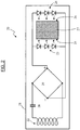
- the lighting apparatus 20 comprises a light guide, thin and transparent, illuminated by its two edges or slices 25, 26 opposite (e) s, by LEDs 23, 24 respectively disposed opposite these two edges .
- the apparatus comprises the necessary number of LEDs which are arranged in rows distributed along one or more of the side faces 25, 26 by which the light emitted by the LEDs is introduced into the guide.
- the LEDs 23, 24 are connected in parallel across an inductor 22.
- the LEDs 23, 24 and the inductor 22 are disposed inside a housing 21 having opaque walls delimiting an opening opposite which extends the light guide 27.
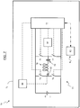
- the apparatus 20 is adapted to be powered by a power supply module 70 which has an inductor 78 connected across an alternating current generator 73.
- the guide 27 has two main faces 50, 51 (that is to say the faces of larger (s) surface or dimensions) which are substantially parallel, and side faces or slices 25, 26 connecting the main faces 50, 51.
- the main faces of the guide may be flat, especially when the guide 27 is in the form of a flat plate, or curved, for example when the guide 27 is in the form of a cylindrical cap or bent plate (left).
- the guide 27 is made of an optical material such as glass, polycarbonate, or polymethylmethacrylate (PMMA), and has a thickness (reference 55 figure 4 ) in a range of about one millimeter to about five millimeters.
- PMMA polymethylmethacrylate
- the "front" main face 50 of the guide is provided with diffusing patterns 52, and a reflector 62 is provided on or against the "rear" face 51 of the guide 27.
- the main "rear" face 51 of the guide is provided with patterns 52 diffusers.
- a reflector is provided on - or against - the "rear” face of the guide, and a diffuser film is further provided on - or against - the "front" face of the guide 27.
- the patterns or diffusing elements 52 may consist of protrusions or elongated depressions, formed or arranged on the face 50.
- the patterns 52 may consist essentially of grooves formed on the face 50 with the aid of a laser beam, the mutual spacing of which varies along at least one axis.
- the spacing of the grooves may decrease regularly from a peripheral zone of the guide to a central zone of the guide.
- the width of the diffusing grooves can be in a range from about 50 microns to about 100 microns.
- the diffusing patterns may extend along axes parallel to the edges of the guide, and / or axes parallel to the rows of LEDs arranged at a short distance from - or against - these edges.
- the diffusing patterns may extend in concentric circles.
- the light 60 emitted by the LEDs undergoes multiple reflections inside the guide 27.
- the diffusing elements 52 cause a scattering of the light emitted by the LEDs and propagating in the guide, towards each of the two faces 50, 51 opposite main of the guide 27.
- the luminous flux respectively emitted by each of the LEDs add up - mix - and result in a homogeneous luminous flux 63 which leaves the guide by its "front" main face 50.
- the LEDs 23 and 24 may have different respective emission spectra.
- the LEDS 23 have an emission spectrum having two maxima for two first wavelengths
- the LEDS 24 have an emission spectrum having two maxima for two seconds wavelengths of which at least one is distinct from the first two wavelengths.
- the first and second wavelengths are generally in the range of about 400 nanometers to about 800 nanometers, so that the LEDs 23, 24 can respectively emit "white” light streams with different color temperatures: bluish light flux whose color temperature may be greater than 5500 Kelvin (K), and a light flux yellowish whose color temperature may be below 5500 K, for example.
- K Kelvin
- some of the LEDs can emit in the infrared or ultraviolet range.
- the "mixing", in the guide 27, of the luminous fluxes of the different LEDs makes it possible to compensate for the disparities in these "individual" fluxes that can result from the disparities observed for the direct voltage of the LEDs of a given model, and even more so to compensate for the disparities of these flows resulting from the use of LEDs of distinct models - which have distinct emission spectra -.
- the apparatus 20 comprises a capacitor 28 and a rectifier 29 connected in series with the inductor 22.
- the capacitance 28 is chosen to form, with the inductor 22, an oscillating circuit tuned on the resonant at a frequency corresponding substantially to the frequency of the generator (reference 70 figures 1 and 7 ), the value of which may be in a range of about 10 to 15 kHz, up to about 25 or 30 kHz.
- the rectifier 29 may be constituted by a bridge of diodes delivering a rectified current between its output terminals, which supplies at least two groups of LEDs 23, 24 connected in parallel, each group of LEDs comprising several LEDS connected in series.
- the LEDs 23, 24 of the CMS type can be mounted on printed circuits 40, 41 ( figure 4 ) extending opposite the slices 25, 26 of the guide 27.
- the apparatus 20 further comprises two switches 30, 31 respectively connected in series with the groups of LEDs 23, 24.
- Each switch may consist essentially of a transistor, in particular a MOSFET field effect transistor.
- the apparatus 20 also comprises a control unit 32, such as a microcontroller, arranged (programmed) to control the opening and closing of the switches 30, 31, via links 36, to provide illumination with the intensity and where appropriate the desired colorimetry.
- a control unit 32 such as a microcontroller, arranged (programmed) to control the opening and closing of the switches 30, 31, via links 36, to provide illumination with the intensity and where appropriate the desired colorimetry.
- control modules (not shown) of pulse width modulation type (“PWM") may be integrated in the unit 32 or interposed between this unit and the switches, to control the power supply of the diodes. 23, 24.
- PWM pulse width modulation type
- the control unit 32 is powered by a power supply module 33 connected to the outputs of the rectifier 29, via conductors 37.
- the control unit 32 is also connected to a signal and / or data transmitter 34 via a bi-directional link 39 and to a motion sensor 35 via a link 38.
- Transmitter 34 may consist essentially of a radio control signal transceiver, in particular a Bluetooth® transmitter.
- the transmitter 34 allows the control unit 32 to receive control data transmitted to the apparatus 20 by another apparatus disposed near the apparatus 20 and equipped with a transmitter compatible with the transmitter 34, such as a remote control device 20.
- the motion sensor 35 may consist essentially of one or more accelerometers (s) or gyrometer (s) integral with the housing 21 of the device 20.
- the sensor 35 may for example comprise two or three accelerometers respectively sensitive to acceleration of the housing in two or three orthogonal axes two by two.
- the motion sensor 35 allows the control unit 32 to detect movements of the lighting apparatus 20 and to modify accordingly the control signals provided by the unit 32 to the switches 30, 31.
- the unit 32 may be programmed to vary (increase or decrease) the luminous flux emitted by the LEDs 23 and / or by the LEDs 24 as a function of the signals delivered to it by the sensor 35.
- the sensor 35 comprises a first accelerometer sensitive to accelerations of the housing along a first axis (a first direction), so as to allow the unit 32 to vary the luminous flux emitted by a first group of LEDs. 23 according to the movements imparted to the housing by a user along this axis, and the sensor 35 comprises a second accelerometer sensitive to acceleration of the housing along a second axis orthogonal to the first axis, so as to allow the unit 32 to vary the luminous flux emitted by a second group of LEDs 24 according to movements imparted to the housing along this second axis.
- the housing comprises a flat wall 43 forming a bottom, and walls 42, 44 extending from the wall 43 and defining an opening 45 which is closed by the guide 27.
- the opaque walls 42 to 44 of the housing and the guide thus prohibit the exit of the light 60 injected by the LEDs into the guide, out of the housing, other than through the front face 50 of the guide.
- the inductor 22 is integral with the wall 43 on the inside of which it extends.
- the inductance 22 acting as an armature may be formed by a conductor having a substantially rectangular spiral shape; it may be the same for the inductor 78 serving as an inductor.
- the inductor 22 may in some cases be made in the form of tracks of a printed circuit, or by winding a conductive wire coated with an insulator; preferably, however, the inductor 22 is made by cutting or etching, from a sheet of conductive material.
- the inductor 22 is formed of a strip or track of a conductive material such as copper, which comprises several successive rectilinear segments such as those marked 46 to 48 figure 9 .
- the inductor 22 has a terminal 49, 53 at each of its two ends, for its connection to the components 28, 29 of the apparatus 20.
- the thickness 54 of the conductive segments of the inductor 22 may be in a range from about 0.2 millimeters to about 0.6 or 1 millimeter, in particular of the order of 0.3 to 0.6 millimeters.
- the width 57 of these segments may be at least equal to their thickness.
- Inductance illustrated figure 9 can be obtained by etching or cutting a copper foil, so as to provide sufficient space between two adjacent conductive segments.
- the spiral conductor thus obtained has a substantially rectangular section and may be coated with or embedded in an insulating material.
- the width 88 of the conductive segments may be at least equal to twice or triple their thickness 87 ( figure 5 ).
- the inductance is obtained by winding a conducting wire 58 of rectangular section coated with an insulator 59, so as to form a spiral with contiguous "turns" having the thickness 54.
- the bottom wall 43 of the housing 21 may have a thickness of the order of one or more millimeters (s), and the housing 21 may have a thickness 56 of the order of 10 or 20 millimeters.
- This wall 43 may be made of plastic, in particular a plastic material comprising a mineral filler in the form of powder or small particles.
- a magnet 61 is partly at least included in the wall 43, on the outer face of which the magnet is substantially flush.
- the magnet makes it possible to suspend the apparatus 20 at a vertical wall 64 including an inductor 78 adapted to supply the apparatus 20 by induction, as illustrated figures 4 , 10, and 11 .
- the wall comprises a metal structure 65 disposed substantially flush with the outer face 66 of the wall 64, and adapted to cause, when placed in the magnetic field of the magnet 61, a force of mutual attraction between the walls 43 and 64 which is sufficient to compensate for the weight of the apparatus 20.
- the housing of the apparatus 20 comprises a flat base 43 by which the apparatus rests on the upper face 86 of a support 68 plane forming part of a piece of furniture 85, the base 43 incorporating the armature 22.
- the housing has opaque walls 42, 44 circling the guide 27 and enclosing, with the guide, the printed circuits 40, 41 receiving the LEDs.
- the housing also comprises an arm 84 connecting the upper part of the housing - ie the walls 42, 44 - to the base 43. Inside the arm 84 run conductors 69 serving to connect the armature 22 to the printed circuits 40, 41 .
- the diffusing patterns 52 cause the luminous flux 63 to be emitted by the two main faces of the guide.
- the support 68 under which the inductor 78 is glued may form at least a portion of the horizontal plate of a piece of furniture 85 such as a table or desk.
- the base 43 and / or the support 68 may be made of a plastic material comprising a mineral filler such as quartz or a hydrate of alumina, which makes it possible to limit the heating of the walls 43, 68 placed in the magnetic field produced by the inductor, without weakening or disturbing this magnetic field, and if necessary to diffuse the heat produced by the LEDs.
- a mineral filler such as quartz or a hydrate of alumina
- the base and the support can be made from Corian® plates proposed by the company Du Pont de Nemours.
- the power supply module - or generator - 70 comprises, inside a housing 71, a converter producing an alternating current at a frequency substantially corresponding to that of the resonant circuit of the apparatus to be supplied.
- the converter comprises an "H" bridge whose central branch consists of the inductor 78 connected in series with a capacitor 79.
- the four switches 74 to 77 of the "H" bridge may consist respectively of four MOSFET transistors.
- control of transistors 74 to 77 is provided by a control unit 72, such as a microcontroller.
- the microcontroller 72 receives for this purpose the signals / data delivered by a converter 80 connected to a current sensitive sensor 83 passing through the inductance 78, on the one hand, and the signals / data delivered (e) s by another converter 81 for measuring the voltage in the bridge, on the other hand.
- the current sensor 83 is inserted in the central branch of the "H" bridge, between the capacitor 79 and the inductor 78.
- the current sensor 83 can be used to detect the variations in the current flowing through inductance 78 and to deduce the presence - or absence thereof - of an armature in the magnetic field produced by inductance 78; it can thus be used to detect the presence of an apparatus to feed by induction.
- the microcontroller 72 is also connected to a transmitter 82 radio, to send control data to the device 20 and / or to receive control data transmitted by a remote control device of the generator 70.
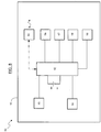
- the remote control device 90 comprises, within a housing 91, a control unit 92, such as a microcontroller, which is connected to a display 93 and to a keyboard having at least one key 94 enabling the validation of choices made by a user.
- a control unit 92 such as a microcontroller
- the microcontroller 92 is also connected to a radio transmitter 95 for sending control data to the apparatus 20 and / or the generator 70, as well as to a clock 96.
- the microcontroller 92 is also connected to three sensors: a sensor 97 responsive to the intensity (overall) of the ambient luminous flux, i.e. the incident flux on the remote control 90; a sensor 98 sensitive to several spectral bands of the ambient luminous flux; and a motion sensitive sensor 99 of the housing 91.
- the sensor 97 may comprise a single photodiode and the sensor 98 may comprise several photodiodes or groups of photodiodes having distinct reception-sensitivity spectrums.
- the control unit 92 can be programmed to transmit, via the transmitter 95, control signals from the lighting apparatus 20, in order to vary the spectrum or the intensity of the light emitted by the LEDs. of this apparatus, in particular according to the signals which are delivered to it by the photodiodes.
- the analysis of the ambient light detected by the photodiodes 97, 98 enables the microcontroller 92 to determine whether the level and / or the spectrum of illumination required by a user requires additional illumination by the LEDs of the apparatus 20.
- the analysis of the signals delivered by the photodiodes can be done "in integral", in for example using a filter corresponding to the sensitivity of a human eye.
- the analysis can be done "in colorimetry", by comparing the level of illumination measured in several spectral bands - i.e., several wavelength ranges - at certain levels of illumination.
- Predetermined levels of illumination may be stored in a memory and may be read by the microcontroller 92 to provide illumination according to a user selected illumination mode.
- the lighting mode can be selected from a constant white light mode, a dimming mode according to a daily cycle, or an intensive lighting mode.
- these can be associated with a (equipped with) a mask making it possible to avoid direct illumination of the sensors by the apparatus 20 and / or by radiation solar direct.
- the sensors 97, 98 may be associated with an optical member providing them with a wide "vision" field, with a filter, or with a frosted glass.
- the sensors 97, 98 can be integrated in the lighting apparatus 20 and connected to the control unit of this apparatus.
- these sensors can be further arranged to receive and detect optical remote control signals transmitted by a suitable optical transmitter integrated in the remote control device 90.
- the sensors 97, 98 may be integrated into a piece of furniture or a structure comprising the induction circuit, and / or to the generator 70.
- the motion sensor 99 enables the control unit 92 to detect movements of the housing 91 and to modify accordingly the control signals delivered by the unit 92, as described above. concerning the motion sensor 35 integrated in the housing of the apparatus 20.
- the furniture 85 comprises a base 100 through which the furniture can rest on the ground for example, and a panel 101 secured to the base and extending vertically from the latter.
- a spiral-shaped inductor 78 of rectangular contour, vertically elongate, and two metal reinforcements 104 in the form of vertical bars are arranged inside the panel 101.
- the base 100 houses a circuit (73 figure 1 ) of the inductor 78, the circuit (not shown) being connected to the two terminals of the inductor.
- the magnetic armatures 104 which extend substantially over the entire height 102 of the inductor 78, allow a luminaire 20 ( figure 11 ) whose height 103 is less than that of the inductor and which is equipped with suitable magnets, to be suspended from the furniture 85 thanks to the force of mutual attraction of the magnets and the frames 104, and this at different heights along the vertical longitudinal axis of the panel 101.
Landscapes
- Engineering & Computer Science (AREA)
- General Engineering & Computer Science (AREA)
- Non-Portable Lighting Devices Or Systems Thereof (AREA)
- Circuit Arrangement For Electric Light Sources In General (AREA)
Claims (15)
- Beleuchtungsvorrichtung (20), mehrere LED (23, 24) umfassend, ein Gehäuse (21), das die LED enthält und opake Wände (42 bis 44) aufweist, die eine Öffnung (45) umgeben, und einen transparenten Lichtleiter (27), der sich der Öffnung (45) zugewandt befindet, wobei die LED und der Lichtleiter derart angeordnet sind, dass der Lichtstrom (60), der von den LED abgestrahlt wird, durch mindestens einen Rand (25, 26) des Lichtleiters mindestens teilweise in den Lichtleiter eintritt, dadurch gekennzeichnet, dass sie außerdem eine Drossel (22) aufweist, an die die LED angeschlossen sind, dadurch, dass mindestens eine Hauptfläche (50, 51) des Lichtleiters Elemente oder streuende Motive (52) trägt, und dadurch, dass sie einen oder mehrere Magnet(e) (61), mit dem Gehäuse fest verbunden, aufweist, die erlauben, die Beleuchtungsvorrichtung mit einer Wand (64) verbunden zu halten, die eine zur Stromversorgung der Beleuchtungsvorrichtung durch Induktion geeignete Induktionsspule (78) trägt.
- Beleuchtungsvorrichtung nach Patentanspruch 1, in der die LED mit mindestens einer gedruckten Schaltung (40, 41) fest verbunden sind.
- Beleuchtungsvorrichtung nach Patentanspruch 1 oder 2, in der die Drossel mit einer Wand (43) der Vorrichtung (20) fest verbunden ist, die aus einem mit mineralischen Teilchen gemischten Kunststoff gefertigt ist.
- Beleuchtungsvorrichtung nach irgendeinem der Patentansprüche 1 bis 3, in der mindestens ein Teil der LED ein Emissionsspektrum aufweist, das zwei Maxima in zwei entsprechenden Wellenlängen aufweist, die sich vorzugsweise in einem Bereich zwischen ungefähr 400 Nanometern und ungefähr 800 Nanometern befinden.
- Beleuchtungsvorrichtung nach irgendeinem der Patentansprüche 1 bis 4, die außerdem einen Kondensator (28) und einen Gleichrichter (29) mit der Drossel (22) in Reihe geschaltet aufweist, wobei der Kondensator mit der Drossel einen Schaltkreis bildet, der auf eine Frequenz abgestimmt ist, die sich vorzugsweise in einem Bereich zwischen ungefähr 10 kHz und ungefähr 30 kHz befindet.
- Beleuchtungsvorrichtung nach irgendeinem der Patentansprüche 1 bis 5, die mehrere in Reihe geschaltete LED aufweist, einen mit den LED in Reihe geschalteten Schalter (30, 31), sowie eine Steuereinheit (32), die dafür eingerichtet ist, die Öffnung und das Schließen des Schalters zu steuern.
- Beleuchtungsvorrichtung nach Patentanspruch 6, die eine erste LED-Gruppe (23) umfasst, die ein Emissionsspektrum aufweist, das zwei Maxima in zwei ersten Wellenlängen aufweist, einen mit den LED der ersten Gruppe in Reihe geschalteten ersten Schalter, eine zweite LED-Gruppe (24), die ein Emissionsspektrum aufweist, das zwei Maxima in zwei zweiten Wellenlängen aufweist, von denen mindestens eine sich von den beiden ersten Wellenlängen unterscheidet, einen mit den LED der zweiten Gruppe in Reihe geschalteten zweiten Schalter, sowie eine Steuereinheit (32), die dafür eingerichtet ist, die Öffnung und das Schließen der Schalter zu steuern.
- Beleuchtungsvorrichtung nach irgendeinem der Patentansprüche 6 oder 7, die einen Funksender (34) aufweist, der mit der Steuereinheit (32) verbunden und dafür eingerichtet ist, der Steuereinheit Steuerdaten zu übermitteln, die von einer in der Nähe der Beleuchtungsvorrichtung angeordneten anderen Vorrichtung an die Beleuchtungsvorrichtung gesendet werden.
- Beleuchtungsvorrichtung nach irgendeinem der Patentansprüche 6 bis 8, die einen Bewegungsmelder (35) mit dem Gehäuse (21) fest verbunden und an die Steuereinheit (32) angeschlossen umfasst, derart, dass der Steuereinheit (32) ermöglicht wird, Bewegungen der Beleuchtungsvorrichtung festzustellen und infolge dieser die von der Einheit (32) an die Schalter (30, 31) ausgegebenen Steuersignale zu ändern, insbesondere um in Abhängigkeit von den vom Sensor (35) ausgegebenen Signalen den von den LED abgestrahlten Lichtstrom zu erhöhen oder zu verringern.
- Beleuchtungsvorrichtung nach irgendeinem der Patentansprüche 1 bis 9, in der die Drossel (22) die Form einer Spirale hat und sich im Wesentlichen parallel zum Lichtleiter (27) erstrecken kann.
- Beleuchtungsvorrichtung nach irgendeinem der Patentansprüche 1 bis 10, die einen Reflektor (62) umfasst, der sich an oder auf einer Hauptfläche (51) des Lichtleiters befindet.
- Beleuchtungsvorrichtung nach irgendeinem der Patentansprüche 1 bis 11, in der der Abstand der streuenden Elemente oder Motive (52) voneinander längs mindestens einer Achse variiert.
- Beleuchtungsvorrichtung nach irgendeinem der Patentansprüche 1 bis 12, in der mindestens ein Teil des Lichtleiters die Form einer ebenen Platte hat.
- Beleuchtungsvorrichtung nach irgendeinem der Patentansprüche 1 bis 13, in der die Drossel (22) im Wesentlichen aus Leitern (46 bis 48) mit im Wesentlichen rechteckigem Querschnitt besteht, die mit einem elektrisch isolierenden Werkstoff überzogen oder in ihn eingebettet sind.
- Induktionsstromversorgungssystem einer Beleuchtungsvorrichtung nach irgendeinem der Patentansprüche 1 bis 14, das ein Möbelstück oder eine Konstruktion umfasst, das/die mit einer Induktionsspule (78), einem Stromgenerator (73), der zur Versorgung der Induktionsspule eingerichtet ist, einer Vorrichtung (90, 92) zur Fernsteuerung des Generators und/oder der Beleuchtungsvorrichtung und mindestens einem Sensor (97, 98), der auf den einfallenden Umgebungslichtstrom empfindlich ist, versehen ist, insbesondere mit mehreren Sensoren, die jeweils auf verschiedene Spektralbereiche des einfallenden Umgebungslichtstroms empfindlich sind, wobei der/die Sensor/en (97, 98) in die Beleuchtungsvorrichtung, in die Fernsteuerungsvorrichtung, in das Möbelstück oder in die Konstruktion eingebaut ist/sind, wobei der/die Sensor/en und die Fernsteuerungsvorrichtung dafür eingerichtet sind, das Spektrum oder die Intensität des von den LED der Beleuchtungsvorrichtung abgestrahlten Lichtes in Abhängigkeit von von dem/n Sensor/en ausgegebenen Signal zu variieren.
Applications Claiming Priority (2)
| Application Number | Priority Date | Filing Date | Title |
|---|---|---|---|
| FR1000024A FR2955011B1 (fr) | 2010-01-05 | 2010-01-05 | Appareil d'eclairage et systeme d'alimentation par induction d'un tel appareil |
| PCT/FR2011/000002 WO2011083258A1 (fr) | 2010-01-05 | 2011-01-04 | Appareil d'éclairage et système d'alimentation par induction d'un tel appareil |
Publications (2)
| Publication Number | Publication Date |
|---|---|
| EP2522201A1 EP2522201A1 (de) | 2012-11-14 |
| EP2522201B1 true EP2522201B1 (de) | 2019-10-16 |
Family
ID=42669511
Family Applications (1)
| Application Number | Title | Priority Date | Filing Date |
|---|---|---|---|
| EP11705001.3A Active EP2522201B1 (de) | 2010-01-05 | 2011-01-04 | Beleuchtungsvorrichtung und induktionssystem zur ausgabe einer solchen vorrichtung |
Country Status (4)
| Country | Link |
|---|---|
| EP (1) | EP2522201B1 (de) |
| BR (1) | BR112012016444A2 (de) |
| FR (1) | FR2955011B1 (de) |
| WO (1) | WO2011083258A1 (de) |
Families Citing this family (5)
| Publication number | Priority date | Publication date | Assignee | Title |
|---|---|---|---|---|
| FR3003008B1 (fr) * | 2013-03-11 | 2018-02-16 | Ipw Europe. | Lampe rechargeable et dispositif de charge |
| FR3009658B1 (fr) | 2013-08-12 | 2017-09-01 | Phlox | Appareil autonome et systeme comportant un tel appareil |
| NO342483B1 (no) * | 2013-09-02 | 2018-05-28 | Nexans | Lyssystem, krafttilførselskabel til lyssystemet og en fremgangsmåte for installering av lyssystemet |
| US10306715B2 (en) | 2015-08-31 | 2019-05-28 | Tridonic Gmbh & Co Kg | Assembly with control gear for lamps |
| CN107257592B (zh) * | 2017-05-23 | 2023-06-16 | 浙江大学 | 隧道无线照明自动调节装置及其无线照明自动调节方法 |
Citations (2)
| Publication number | Priority date | Publication date | Assignee | Title |
|---|---|---|---|---|
| WO2003085428A1 (fr) * | 2002-04-05 | 2003-10-16 | Phlox (S.A.) | Appareil de retro-eclairage |
| WO2008012702A1 (en) * | 2006-07-21 | 2008-01-31 | Philips Intellectual Property & Standards Gmbh | Lighting system |
Family Cites Families (4)
| Publication number | Priority date | Publication date | Assignee | Title |
|---|---|---|---|---|
| US5264997A (en) | 1992-03-04 | 1993-11-23 | Dominion Automotive Industries Corp. | Sealed, inductively powered lamp assembly |
| JP4823568B2 (ja) * | 2005-05-23 | 2011-11-24 | 三菱電機株式会社 | 面状光源装置及びこれを用いた表示装置 |
| US7771085B2 (en) * | 2007-01-16 | 2010-08-10 | Steven Kim | Circular LED panel light |
| CN101469850A (zh) * | 2007-12-25 | 2009-07-01 | 富士迈半导体精密工业(上海)有限公司 | 固态照明灯具 |
-
2010
- 2010-01-05 FR FR1000024A patent/FR2955011B1/fr not_active Expired - Fee Related
-
2011
- 2011-01-04 EP EP11705001.3A patent/EP2522201B1/de active Active
- 2011-01-04 WO PCT/FR2011/000002 patent/WO2011083258A1/fr not_active Ceased
- 2011-01-04 BR BR112012016444-9A patent/BR112012016444A2/pt not_active Application Discontinuation
Patent Citations (2)
| Publication number | Priority date | Publication date | Assignee | Title |
|---|---|---|---|---|
| WO2003085428A1 (fr) * | 2002-04-05 | 2003-10-16 | Phlox (S.A.) | Appareil de retro-eclairage |
| WO2008012702A1 (en) * | 2006-07-21 | 2008-01-31 | Philips Intellectual Property & Standards Gmbh | Lighting system |
Also Published As
| Publication number | Publication date |
|---|---|
| FR2955011A1 (fr) | 2011-07-08 |
| WO2011083258A1 (fr) | 2011-07-14 |
| EP2522201A1 (de) | 2012-11-14 |
| BR112012016444A2 (pt) | 2018-05-15 |
| FR2955011B1 (fr) | 2012-02-24 |
Similar Documents
| Publication | Publication Date | Title |
|---|---|---|
| US8506116B2 (en) | Shelf lighting device and method | |
| WO2011083258A1 (fr) | Appareil d'éclairage et système d'alimentation par induction d'un tel appareil | |
| US7934845B2 (en) | Candle like lighting device | |
| EP1052917B1 (de) | Verbessertes illuminieren von edelsteinen | |
| EP1373787B1 (de) | Beleuchtungselement und leuchte mit diesem element | |
| EP2695490B1 (de) | Programmierbare led-beleuchtungsvorrichtung und verfahren | |
| CN100426050C (zh) | 体积型透镜、发光体、照明器具及光信息系统 | |
| CN104040810B (zh) | 具有波长测量功能的波长可变激光装置 | |
| KR20090077054A (ko) | 유기 발광 소자 및 조명 장치 | |
| WO2007099860A1 (ja) | Led照明器具 | |
| FR2962306A1 (fr) | Emballage et systeme comprenant un contenant et des moyens visuels aptes a exprimer une pluralite de structures visuelles. | |
| EP0377352A1 (de) | Biegsames Leuchtband mit Leuchtdioden | |
| EP3234453A1 (de) | Licht- und/oder signalisierungsvorrichtung mit einem lichtleiter | |
| EP2996142A1 (de) | Halterung für leuchtquelle mit integriertem anschluss | |
| FR2883653A1 (fr) | Module electronique et carte a puce avec indicateur lumineux | |
| WO2016113497A1 (fr) | Récipient, composant de récipient, et gamme de tels produits | |
| FR2954994B1 (fr) | Systeme d'alimentation par induction et meuble pour un tel systeme | |
| EP3033818B1 (de) | Autonome vorrichtung und system mit solch einer vorrichtung | |
| WO2017207923A1 (fr) | Conditionnement d'un liquide transparent | |
| CN108614383A (zh) | 泛光灯组件、泛光灯损坏的检测方法和电子装置 | |
| FR3119222A3 (fr) | Corps d'éclairage pour lampes | |
| US20130294075A1 (en) | Lighting system and method of manufacture | |
| RU2464597C2 (ru) | Осветительное устройство | |
| CH701348B1 (fr) | Système d'éclairage bijoux à sources lumineuses mobiles. | |
| RU2297784C2 (ru) | Прозрачный сосуд и способ его подсветки |
Legal Events
| Date | Code | Title | Description |
|---|---|---|---|
| PUAI | Public reference made under article 153(3) epc to a published international application that has entered the european phase |
Free format text: ORIGINAL CODE: 0009012 |
|
| 17P | Request for examination filed |
Effective date: 20120806 |
|
| AK | Designated contracting states |
Kind code of ref document: A1 Designated state(s): AL AT BE BG CH CY CZ DE DK EE ES FI FR GB GR HR HU IE IS IT LI LT LU LV MC MK MT NL NO PL PT RO RS SE SI SK SM TR |
|
| DAX | Request for extension of the european patent (deleted) | ||
| STAA | Information on the status of an ep patent application or granted ep patent |
Free format text: STATUS: EXAMINATION IS IN PROGRESS |
|
| 17Q | First examination report despatched |
Effective date: 20161109 |
|
| REG | Reference to a national code |
Ref country code: DE Ref legal event code: R079 Ref document number: 602011062738 Country of ref document: DE Free format text: PREVIOUS MAIN CLASS: H05B0033080000 Ipc: F21V0021096000 |
|
| GRAP | Despatch of communication of intention to grant a patent |
Free format text: ORIGINAL CODE: EPIDOSNIGR1 |
|
| STAA | Information on the status of an ep patent application or granted ep patent |
Free format text: STATUS: GRANT OF PATENT IS INTENDED |
|
| RIC1 | Information provided on ipc code assigned before grant |
Ipc: F21V 21/096 20060101AFI20181102BHEP Ipc: F21V 23/04 20060101ALI20181102BHEP Ipc: F21Y 105/00 20060101ALI20181102BHEP Ipc: F21V 8/00 20060101ALI20181102BHEP Ipc: F21Y 115/10 20121114ALI20181102BHEP Ipc: F21Y 113/13 20121114ALI20181102BHEP Ipc: H05B 33/08 20060101ALI20181102BHEP |
|
| RIC1 | Information provided on ipc code assigned before grant |
Ipc: F21Y 115/10 20160101ALI20181102BHEP Ipc: F21Y 105/00 20160101ALI20181102BHEP Ipc: F21V 21/096 20060101AFI20181102BHEP Ipc: F21Y 113/13 20160101ALI20181102BHEP Ipc: F21V 8/00 20060101ALI20181102BHEP Ipc: F21V 23/04 20060101ALI20181102BHEP Ipc: H05B 33/08 20060101ALI20181102BHEP |
|
| INTG | Intention to grant announced |
Effective date: 20181211 |
|
| RIC1 | Information provided on ipc code assigned before grant |
Ipc: F21V 8/00 20060101ALI20181102BHEP Ipc: F21V 23/04 20060101ALI20181102BHEP Ipc: F21V 21/096 20060101AFI20181102BHEP Ipc: H05B 33/08 20060101ALI20181102BHEP Ipc: F21Y 105/00 20160101ALI20181102BHEP Ipc: F21Y 115/10 20160101ALI20181102BHEP Ipc: F21Y 113/13 20160101ALI20181102BHEP |
|
| RAP1 | Party data changed (applicant data changed or rights of an application transferred) |
Owner name: PHLOX |
|
| GRAS | Grant fee paid |
Free format text: ORIGINAL CODE: EPIDOSNIGR3 |
|
| GRAA | (expected) grant |
Free format text: ORIGINAL CODE: 0009210 |
|
| STAA | Information on the status of an ep patent application or granted ep patent |
Free format text: STATUS: THE PATENT HAS BEEN GRANTED |
|
| AK | Designated contracting states |
Kind code of ref document: B1 Designated state(s): AL AT BE BG CH CY CZ DE DK EE ES FI FR GB GR HR HU IE IS IT LI LT LU LV MC MK MT NL NO PL PT RO RS SE SI SK SM TR |
|
| REG | Reference to a national code |
Ref country code: GB Ref legal event code: FG4D Free format text: NOT ENGLISH |
|
| REG | Reference to a national code |
Ref country code: CH Ref legal event code: EP |
|
| REG | Reference to a national code |
Ref country code: DE Ref legal event code: R096 Ref document number: 602011062738 Country of ref document: DE |
|
| REG | Reference to a national code |
Ref country code: IE Ref legal event code: FG4D Free format text: LANGUAGE OF EP DOCUMENT: FRENCH |
|
| REG | Reference to a national code |
Ref country code: AT Ref legal event code: REF Ref document number: 1191633 Country of ref document: AT Kind code of ref document: T Effective date: 20191115 |
|
| REG | Reference to a national code |
Ref country code: NL Ref legal event code: FP |
|
| REG | Reference to a national code |
Ref country code: LT Ref legal event code: MG4D |
|
| REG | Reference to a national code |
Ref country code: CH Ref legal event code: NV Representative=s name: VALIPAT S.A. C/O BOVARD SA NEUCHATEL, CH |
|
| REG | Reference to a national code |
Ref country code: AT Ref legal event code: MK05 Ref document number: 1191633 Country of ref document: AT Kind code of ref document: T Effective date: 20191016 |
|
| PG25 | Lapsed in a contracting state [announced via postgrant information from national office to epo] |
Ref country code: PT Free format text: LAPSE BECAUSE OF FAILURE TO SUBMIT A TRANSLATION OF THE DESCRIPTION OR TO PAY THE FEE WITHIN THE PRESCRIBED TIME-LIMIT Effective date: 20200217 Ref country code: BG Free format text: LAPSE BECAUSE OF FAILURE TO SUBMIT A TRANSLATION OF THE DESCRIPTION OR TO PAY THE FEE WITHIN THE PRESCRIBED TIME-LIMIT Effective date: 20200116 Ref country code: FI Free format text: LAPSE BECAUSE OF FAILURE TO SUBMIT A TRANSLATION OF THE DESCRIPTION OR TO PAY THE FEE WITHIN THE PRESCRIBED TIME-LIMIT Effective date: 20191016 Ref country code: NO Free format text: LAPSE BECAUSE OF FAILURE TO SUBMIT A TRANSLATION OF THE DESCRIPTION OR TO PAY THE FEE WITHIN THE PRESCRIBED TIME-LIMIT Effective date: 20200116 Ref country code: PL Free format text: LAPSE BECAUSE OF FAILURE TO SUBMIT A TRANSLATION OF THE DESCRIPTION OR TO PAY THE FEE WITHIN THE PRESCRIBED TIME-LIMIT Effective date: 20191016 Ref country code: GR Free format text: LAPSE BECAUSE OF FAILURE TO SUBMIT A TRANSLATION OF THE DESCRIPTION OR TO PAY THE FEE WITHIN THE PRESCRIBED TIME-LIMIT Effective date: 20200117 Ref country code: LV Free format text: LAPSE BECAUSE OF FAILURE TO SUBMIT A TRANSLATION OF THE DESCRIPTION OR TO PAY THE FEE WITHIN THE PRESCRIBED TIME-LIMIT Effective date: 20191016 Ref country code: SE Free format text: LAPSE BECAUSE OF FAILURE TO SUBMIT A TRANSLATION OF THE DESCRIPTION OR TO PAY THE FEE WITHIN THE PRESCRIBED TIME-LIMIT Effective date: 20191016 Ref country code: AT Free format text: LAPSE BECAUSE OF FAILURE TO SUBMIT A TRANSLATION OF THE DESCRIPTION OR TO PAY THE FEE WITHIN THE PRESCRIBED TIME-LIMIT Effective date: 20191016 Ref country code: ES Free format text: LAPSE BECAUSE OF FAILURE TO SUBMIT A TRANSLATION OF THE DESCRIPTION OR TO PAY THE FEE WITHIN THE PRESCRIBED TIME-LIMIT Effective date: 20191016 Ref country code: LT Free format text: LAPSE BECAUSE OF FAILURE TO SUBMIT A TRANSLATION OF THE DESCRIPTION OR TO PAY THE FEE WITHIN THE PRESCRIBED TIME-LIMIT Effective date: 20191016 |
|
| PG25 | Lapsed in a contracting state [announced via postgrant information from national office to epo] |
Ref country code: IS Free format text: LAPSE BECAUSE OF FAILURE TO SUBMIT A TRANSLATION OF THE DESCRIPTION OR TO PAY THE FEE WITHIN THE PRESCRIBED TIME-LIMIT Effective date: 20200224 Ref country code: HR Free format text: LAPSE BECAUSE OF FAILURE TO SUBMIT A TRANSLATION OF THE DESCRIPTION OR TO PAY THE FEE WITHIN THE PRESCRIBED TIME-LIMIT Effective date: 20191016 Ref country code: RS Free format text: LAPSE BECAUSE OF FAILURE TO SUBMIT A TRANSLATION OF THE DESCRIPTION OR TO PAY THE FEE WITHIN THE PRESCRIBED TIME-LIMIT Effective date: 20191016 |
|
| PG25 | Lapsed in a contracting state [announced via postgrant information from national office to epo] |
Ref country code: AL Free format text: LAPSE BECAUSE OF FAILURE TO SUBMIT A TRANSLATION OF THE DESCRIPTION OR TO PAY THE FEE WITHIN THE PRESCRIBED TIME-LIMIT Effective date: 20191016 |
|
| REG | Reference to a national code |
Ref country code: DE Ref legal event code: R097 Ref document number: 602011062738 Country of ref document: DE |
|
| PG2D | Information on lapse in contracting state deleted |
Ref country code: IS |
|
| PG25 | Lapsed in a contracting state [announced via postgrant information from national office to epo] |
Ref country code: DK Free format text: LAPSE BECAUSE OF FAILURE TO SUBMIT A TRANSLATION OF THE DESCRIPTION OR TO PAY THE FEE WITHIN THE PRESCRIBED TIME-LIMIT Effective date: 20191016 Ref country code: EE Free format text: LAPSE BECAUSE OF FAILURE TO SUBMIT A TRANSLATION OF THE DESCRIPTION OR TO PAY THE FEE WITHIN THE PRESCRIBED TIME-LIMIT Effective date: 20191016 Ref country code: RO Free format text: LAPSE BECAUSE OF FAILURE TO SUBMIT A TRANSLATION OF THE DESCRIPTION OR TO PAY THE FEE WITHIN THE PRESCRIBED TIME-LIMIT Effective date: 20191016 Ref country code: CZ Free format text: LAPSE BECAUSE OF FAILURE TO SUBMIT A TRANSLATION OF THE DESCRIPTION OR TO PAY THE FEE WITHIN THE PRESCRIBED TIME-LIMIT Effective date: 20191016 Ref country code: IS Free format text: LAPSE BECAUSE OF FAILURE TO SUBMIT A TRANSLATION OF THE DESCRIPTION OR TO PAY THE FEE WITHIN THE PRESCRIBED TIME-LIMIT Effective date: 20200216 |
|
| PLBE | No opposition filed within time limit |
Free format text: ORIGINAL CODE: 0009261 |
|
| STAA | Information on the status of an ep patent application or granted ep patent |
Free format text: STATUS: NO OPPOSITION FILED WITHIN TIME LIMIT |
|
| PG25 | Lapsed in a contracting state [announced via postgrant information from national office to epo] |
Ref country code: MC Free format text: LAPSE BECAUSE OF FAILURE TO SUBMIT A TRANSLATION OF THE DESCRIPTION OR TO PAY THE FEE WITHIN THE PRESCRIBED TIME-LIMIT Effective date: 20191016 Ref country code: SM Free format text: LAPSE BECAUSE OF FAILURE TO SUBMIT A TRANSLATION OF THE DESCRIPTION OR TO PAY THE FEE WITHIN THE PRESCRIBED TIME-LIMIT Effective date: 20191016 Ref country code: SK Free format text: LAPSE BECAUSE OF FAILURE TO SUBMIT A TRANSLATION OF THE DESCRIPTION OR TO PAY THE FEE WITHIN THE PRESCRIBED TIME-LIMIT Effective date: 20191016 |
|
| 26N | No opposition filed |
Effective date: 20200717 |
|
| PG25 | Lapsed in a contracting state [announced via postgrant information from national office to epo] |
Ref country code: LU Free format text: LAPSE BECAUSE OF NON-PAYMENT OF DUE FEES Effective date: 20200104 |
|
| PG25 | Lapsed in a contracting state [announced via postgrant information from national office to epo] |
Ref country code: SI Free format text: LAPSE BECAUSE OF FAILURE TO SUBMIT A TRANSLATION OF THE DESCRIPTION OR TO PAY THE FEE WITHIN THE PRESCRIBED TIME-LIMIT Effective date: 20191016 |
|
| PG25 | Lapsed in a contracting state [announced via postgrant information from national office to epo] |
Ref country code: TR Free format text: LAPSE BECAUSE OF FAILURE TO SUBMIT A TRANSLATION OF THE DESCRIPTION OR TO PAY THE FEE WITHIN THE PRESCRIBED TIME-LIMIT Effective date: 20191016 Ref country code: MT Free format text: LAPSE BECAUSE OF FAILURE TO SUBMIT A TRANSLATION OF THE DESCRIPTION OR TO PAY THE FEE WITHIN THE PRESCRIBED TIME-LIMIT Effective date: 20191016 Ref country code: CY Free format text: LAPSE BECAUSE OF FAILURE TO SUBMIT A TRANSLATION OF THE DESCRIPTION OR TO PAY THE FEE WITHIN THE PRESCRIBED TIME-LIMIT Effective date: 20191016 |
|
| PG25 | Lapsed in a contracting state [announced via postgrant information from national office to epo] |
Ref country code: MK Free format text: LAPSE BECAUSE OF FAILURE TO SUBMIT A TRANSLATION OF THE DESCRIPTION OR TO PAY THE FEE WITHIN THE PRESCRIBED TIME-LIMIT Effective date: 20191016 |
|
| PGFP | Annual fee paid to national office [announced via postgrant information from national office to epo] |
Ref country code: NL Payment date: 20221220 Year of fee payment: 13 Ref country code: IE Payment date: 20221222 Year of fee payment: 13 Ref country code: GB Payment date: 20221221 Year of fee payment: 13 |
|
| PGFP | Annual fee paid to national office [announced via postgrant information from national office to epo] |
Ref country code: BE Payment date: 20221220 Year of fee payment: 13 |
|
| PGFP | Annual fee paid to national office [announced via postgrant information from national office to epo] |
Ref country code: CH Payment date: 20230201 Year of fee payment: 13 |
|
| PGFP | Annual fee paid to national office [announced via postgrant information from national office to epo] |
Ref country code: IT Payment date: 20230103 Year of fee payment: 13 Ref country code: DE Payment date: 20221220 Year of fee payment: 13 |
|
| REG | Reference to a national code |
Ref country code: DE Ref legal event code: R119 Ref document number: 602011062738 Country of ref document: DE |
|
| REG | Reference to a national code |
Ref country code: CH Ref legal event code: PL |
|
| REG | Reference to a national code |
Ref country code: NL Ref legal event code: MM Effective date: 20240201 |
|
| GBPC | Gb: european patent ceased through non-payment of renewal fee |
Effective date: 20240104 |
|
| PG25 | Lapsed in a contracting state [announced via postgrant information from national office to epo] |
Ref country code: DE Free format text: LAPSE BECAUSE OF NON-PAYMENT OF DUE FEES Effective date: 20240801 |
|
| PG25 | Lapsed in a contracting state [announced via postgrant information from national office to epo] |
Ref country code: GB Free format text: LAPSE BECAUSE OF NON-PAYMENT OF DUE FEES Effective date: 20240104 |
|
| PG25 | Lapsed in a contracting state [announced via postgrant information from national office to epo] |
Ref country code: BE Free format text: LAPSE BECAUSE OF NON-PAYMENT OF DUE FEES Effective date: 20240131 |
|
| PG25 | Lapsed in a contracting state [announced via postgrant information from national office to epo] |
Ref country code: NL Free format text: LAPSE BECAUSE OF NON-PAYMENT OF DUE FEES Effective date: 20240201 |
|
| PG25 | Lapsed in a contracting state [announced via postgrant information from national office to epo] |
Ref country code: CH Free format text: LAPSE BECAUSE OF NON-PAYMENT OF DUE FEES Effective date: 20240131 |
|
| PG25 | Lapsed in a contracting state [announced via postgrant information from national office to epo] |
Ref country code: NL Free format text: LAPSE BECAUSE OF NON-PAYMENT OF DUE FEES Effective date: 20240201 Ref country code: GB Free format text: LAPSE BECAUSE OF NON-PAYMENT OF DUE FEES Effective date: 20240104 Ref country code: DE Free format text: LAPSE BECAUSE OF NON-PAYMENT OF DUE FEES Effective date: 20240801 Ref country code: CH Free format text: LAPSE BECAUSE OF NON-PAYMENT OF DUE FEES Effective date: 20240131 Ref country code: BE Free format text: LAPSE BECAUSE OF NON-PAYMENT OF DUE FEES Effective date: 20240131 |
|
| REG | Reference to a national code |
Ref country code: BE Ref legal event code: MM Effective date: 20240131 |
|
| PG25 | Lapsed in a contracting state [announced via postgrant information from national office to epo] |
Ref country code: IE Free format text: LAPSE BECAUSE OF NON-PAYMENT OF DUE FEES Effective date: 20240104 |
|
| PG25 | Lapsed in a contracting state [announced via postgrant information from national office to epo] |
Ref country code: IE Free format text: LAPSE BECAUSE OF NON-PAYMENT OF DUE FEES Effective date: 20240104 |
|
| PG25 | Lapsed in a contracting state [announced via postgrant information from national office to epo] |
Ref country code: IT Free format text: LAPSE BECAUSE OF NON-PAYMENT OF DUE FEES Effective date: 20240104 |
|
| PGFP | Annual fee paid to national office [announced via postgrant information from national office to epo] |
Ref country code: FR Payment date: 20260116 Year of fee payment: 16 |