EP2695490B1 - Programmierbare led-beleuchtungsvorrichtung und verfahren - Google Patents
Programmierbare led-beleuchtungsvorrichtung und verfahren Download PDFInfo
- Publication number
- EP2695490B1 EP2695490B1 EP12721329.6A EP12721329A EP2695490B1 EP 2695490 B1 EP2695490 B1 EP 2695490B1 EP 12721329 A EP12721329 A EP 12721329A EP 2695490 B1 EP2695490 B1 EP 2695490B1
- Authority
- EP
- European Patent Office
- Prior art keywords
- leds
- cut
- spotlights
- microprocessor
- lighting device
- Prior art date
- Legal status (The legal status is an assumption and is not a legal conclusion. Google has not performed a legal analysis and makes no representation as to the accuracy of the status listed.)
- Active
Links
Images


Classifications
-
- H—ELECTRICITY
- H05—ELECTRIC TECHNIQUES NOT OTHERWISE PROVIDED FOR
- H05B—ELECTRIC HEATING; ELECTRIC LIGHT SOURCES NOT OTHERWISE PROVIDED FOR; CIRCUIT ARRANGEMENTS FOR ELECTRIC LIGHT SOURCES, IN GENERAL
- H05B45/00—Circuit arrangements for operating light-emitting diodes [LED]
- H05B45/20—Controlling the colour of the light
-
- H—ELECTRICITY
- H05—ELECTRIC TECHNIQUES NOT OTHERWISE PROVIDED FOR
- H05B—ELECTRIC HEATING; ELECTRIC LIGHT SOURCES NOT OTHERWISE PROVIDED FOR; CIRCUIT ARRANGEMENTS FOR ELECTRIC LIGHT SOURCES, IN GENERAL
- H05B47/00—Circuit arrangements for operating light sources in general, i.e. where the type of light source is not relevant
- H05B47/10—Controlling the light source
- H05B47/175—Controlling the light source by remote control
- H05B47/185—Controlling the light source by remote control via power line carrier transmission
-
- H—ELECTRICITY
- H05—ELECTRIC TECHNIQUES NOT OTHERWISE PROVIDED FOR
- H05B—ELECTRIC HEATING; ELECTRIC LIGHT SOURCES NOT OTHERWISE PROVIDED FOR; CIRCUIT ARRANGEMENTS FOR ELECTRIC LIGHT SOURCES, IN GENERAL
- H05B47/00—Circuit arrangements for operating light sources in general, i.e. where the type of light source is not relevant
- H05B47/10—Controlling the light source
- H05B47/175—Controlling the light source by remote control
- H05B47/19—Controlling the light source by remote control via wireless transmission
-
- H—ELECTRICITY
- H05—ELECTRIC TECHNIQUES NOT OTHERWISE PROVIDED FOR
- H05B—ELECTRIC HEATING; ELECTRIC LIGHT SOURCES NOT OTHERWISE PROVIDED FOR; CIRCUIT ARRANGEMENTS FOR ELECTRIC LIGHT SOURCES, IN GENERAL
- H05B47/00—Circuit arrangements for operating light sources in general, i.e. where the type of light source is not relevant
- H05B47/10—Controlling the light source
- H05B47/175—Controlling the light source by remote control
- H05B47/198—Grouping of control procedures or address assignation to light sources
- H05B47/199—Commissioning of light sources
Definitions
- the invention relates to a programmable LED lighting method and device.
- the present invention relates to the field of lighting, in particular in the aquatic environment.
- a lighting device comprising one or more submersible devices, also called underwater projectors, used for lighting pool pools and their direct environment (beach, terraces, gardens ). It also applies to lighting fountains, spas, or other places, as well as lighting in an air environment.
- Submerged floodlights or underwater floodlights for swimming pool lighting are nowadays widely used to illuminate the water of the pools and their environment, at nightfall, in order to secure the premises and provide an aesthetic rendering. More specifically, the invention applies to projectors using LED technology labeled with LEDs or LEDs for "light-emitting diode", which contain a set of high-brightness LEDs (see for example documents EP-1840450 , EP-1460333 ).
- LED spotlights are very economical. They consume very small amounts of energy (only a few watts) and have a very long life (more than 10 years in daily use). LEDs are also stronger, have a much longer life than incandescent or fluorescent lamps, and have a yield three to four times higher than these.
- the remote control of the color change can be done by transmission of information by radio waves or wired or by using a power cable for transmission medium (line carrier current - CPL), see for example the document FR-2931925 .
- line carrier current - CPL line carrier current - CPL
- the document US-2002/0163316 describes, for example, a device consisting in causing a rapid shutdown of the power supply of the LEDs.
- These systems are provided with a detection device for detecting the cutoff allowing the color change, and this, thanks to the energy accumulated generally in capacitors equipping the projector.
- Such operations can only be performed by operating a switch to cause a rapid cut that should not be too short or too long for the energy accumulated in the projectors to maintain the power supply of the device detection during the cut-off time.
- the color change occurs incrementally and in a predefined order.
- a cut of width too short could be likened to a spurious signal, thus generating the possibility of desynchronization of the projectors occurring when they do not detect the cut, and a break of width too long could be likened to a break power supply because of a response time too long and thus cause the extinction of the projectors.
- the object of the invention is in particular to overcome the disadvantages of the prior art, in particular the disadvantages resulting from the implementation of the devices described above.
- Another object of the present invention is to provide a method and a lighting device that can receive and interpret a code for changing the mode of operation of the projectors while being relatively simple and inexpensive.
- Another objective is to propose a method and a device that makes it possible to instantly and easily change the color of the projectors.
- a lighting device in particular an underwater lighting device comprising a plurality of projectors each comprising at least one light source constituted by a set of LEDs capable of emitting different colored lights, said plurality of projectors being connected to a power source, and at least one housing of control connected to said power source.
- the control unit is equipped with a cut-off device designed to transmit, via a power cut-off device, advantageously constituted by a relay or by a triac, control instructions to the projectors in the form of successions of short and long cuts of food.
- the projectors are equipped with an embedded detector equipped with a microprocessor adapted or configured to interpret said control instructions and to modulate a signal capable of modifying the color of each of the LEDs comprising all the LEDs.
- This device is remarkable in that the control instructions issued by the switching device of the control box are transmitted in the form of a code consisting of combinations of short and long cuts of the power supply.
- the light source consists of a set of LEDs each of which is capable of emitting a single color.
- the light source consists of LEDs of different colors, each of which is capable of emitting a plurality of colors, the LEDs being, for example, RGB LEDs.
- control unit is provided with keys making it possible to select an operating mode associated with a control instruction transmitted in the form of combinations of cuts in the power supply.
- control unit comprises a microprocessor coupled to a time base making it possible to cut off power supply of a precise duration.
- the cutoff device and more precisely the microprocessor is configured to generate combinations of m short and long cuts of the power supply.
- power cuts are between 100 and 300 ms for a so-called “short” cut and between 300 and 500 ms for a so-called "long” cut.
- the device comprises a remote control communicating wirelessly with the control box, the latter being provided with a radio receiver constituted by an antenna.
- the microprocessor of the on-board detector comprises a program comprising the different operating modes so as to interpret said control instructions transmitted by the microprocessor of the transmitter and to modulate a signal capable of modifying the color of each of the LEDs comprising all the LEDs.
- the invention also relates to a lighting method, in particular underwater lighting of the kind comprising a plurality of projectors each comprising at least one light source consisting of a set of LEDs capable of emitting lights of different colors, said plurality of projectors being connected to a power source; and at least one control box connected to said power source and communicating with each of the projectors.
- control box is configured to generate a code consisting of short and long cuts of the power supply, or combinations of such cuts, and to transmit control instructions capable of modifying the color of each of the LEDs comprising all the LEDs, and the projectors are equipped with an embedded detector equipped with a microprocessor capable of interpreting said control instructions transmitted by the control box in the form of a succession of power cuts.
- a mode of operation of the projector is selected by means of the keys of the control box, said modes of operation being associated with control instructions.
- the supply interruptions generated by the control box are detected and their duration measured by the detector of the projectors equipped with a microprocessor, which interprets said code consisting of all the cuts and modulates a signal for modifying the mode of operation of the projectors.
- the microprocessor generates combinations of m short and long cuts of the power supply.
- the microprocessor of the on-board detector is programmed with the various modes of operation of the projectors so as to interpret the said control instructions transmitted by the microprocessor of the transmitter and to modulate a signal capable of modifying the color of each of the LEDs. all the LEDs.
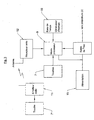
- the figure 1 schematically illustrates an installation applying the lighting device according to the invention.
- This lighting device 1 mainly comprises a plurality of projectors 2 equipping the walls of a pool P and each having one or more light sources consisting of a set of LEDs 3 ( figures 2 and 4 ) capable of emitting lights of different colors, said light source being connected to a power source ( figures 2 , 3 and 4 ).
- the projectors 2 generally comprise a sealed body to be installed in a swimming pool P and / or near the pool P and may have various shapes.
- the lighting device 1 further comprises at least one control unit 4 arranged, generally, at a distance from the swimming pool P, on a building wall, for example, inside a dwelling.
- the control unit 4 is also connected to the power source and controls the power supply of each of the projectors 2.
- This control unit 4 is provided with keys 7, a radio wave antenna 6 and a power cut-off device 5.
- the cutoff device 5 of the control box 4 is configured to transmit, via a cut-off device, advantageously constituted by a relay or by a triac, or any other breaking system, instructions control circuit IC capable of modifying the color of each of the LEDs 3 constituting the sets of LEDs 3.
- the control instructions IC are transmitted to the projectors 2 which are equipped with an on-board detector 8, described below and able to interpret this kind IC instructions.
- IC control instructions come in the form of combinations of power cuts that are intended to change the mode operating a projector 2, or a group of projectors 2, or all projectors 2 at the same time.
- the keys 7 installed on the control box 4 allow a user to easily choose a mode of operation of the projectors 2 and, more particularly, to change the desired color for the lighting of the pool P. More specifically, the keys 7 make it possible to select a combination of power cuts that change the color of the LEDs 3.
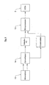
- the cut-off device 5 installed in the control box 4, according to the invention, comprises various electronic components known per se and in particular a microprocessor 9 which is configured to generate a code consisting of combinations of short and long cuts of the power supply. These combinations of cuts are perceived as a message interpretable by the projectors 2.
- this cut-off device 5 is mounted at the source of the supply of the projectors 2.
- the cuts constituting the combinations are in a predetermined number and are of varied durations (long and short) predetermined. These cuts are also sufficiently spaced apart to be detected and interpreted by the projectors 2 with a low error rate.
- the microprocessor 9 of the cut-off device 5 is coupled to a time base 10 enabling it to make these cuts of a precise duration to within 1 ms.
- This time base 10 may be constituted by an oscillator internal to the microprocessor 9 or by a quartz oscillator.
- the combinations of cuts thus form a coding in the manner of the walrus, delivering information or instructions that correspond to the different modes of operation that the projectors can adopt 2.
- it is the combination of several short and long cuts of the feed that is sent in a salvo for a defined time that allows to obtain the vocabulary of the device and to constitute a set of instructions.
- the information is therefore interpreted by the projectors 2 when the burst of cuts is completely received.
- This interesting feature of the invention provides several beneficial advantages including the possibility of having a larger vocabulary but above all there is no error detection or misinterpretation, by the device of the invention, coding constituted by the combination of short and long cuts of food.
- a combination of power cuts has, for example, a duration of between 50 ms and 2 s.
- the duration of a so-called “short” power failure can vary between 100 and 300 ms and the duration of a so-called “long” power failure can vary between 300 and 500 ms.
- the short cuts must be long enough not to be confused with the frequent micro-cuts occurring on the electrical networks, while the long cuts must be short enough not to cause the malfunction of the projectors 2.
- the lighting device 1 may comprise a remote control 11 communicating wirelessly with the control unit 4.
- the latter is equipped with a radio receiver 12 called to capture the information transmitted by the remote control 11, the latter being also equipped with keys 7 '.
- the user can choose, remotely, the mode of operation of the projectors 2 and therefore the desired color wherever it is.
- the projector 2 as described above, comprises one or more light sources consisting of a set of LEDs 3. These are generally high power LEDs 3 well known to those skilled in the art.
- the light source consists of LEDs that can emit a single color, that is to say LEDs of white color, or red, or green, or blue, or yellow etc.
- This source of The light may also consist of LEDs 3 of different colors, generally red, green and blue, whose combination of emissions makes it possible to obtain a very large variety of hues. It is still possible to use LEDs each emitting the 3 basic colors (red, green and blue).
- These LEDs 3a are better known as RGB LEDs (Red / Green / Blue) or RGB LEDs for English (Red / Green / Blue).
- the single-color LEDs 3 and / or the RGB LEDs are assembled on the same electronic card in the projector 2, this electronic card comprising the electronic components of the projector 2.
- the LEDs 3 can be mounted on a card different from that provided for said components.
- the on-board detector 8 installed on an electronic card known per se, in the projector 2, comprises a microprocessor 13 configured to interpret the control instructions IC sent by the breaking device 5 of the control unit 4.
- This microprocessor 13 comprises a program consisting of different modes of operation that the projector can adopt so that it can easily interpret the power cut combinations constituting the received IC command commands.
- the microprocessor 13 modulates a signal to change, for example, the color of the LEDs 3.
- the on-board detector 8 requires a DC power supply obtained by an AC / DC rectifier or AC / DC converter 14, and which by construction integrates a capacitor of large capacity for filtering the alternating current.
- This capacitor makes it possible to have a reserve of energy or memory, which during power cuts intended to change the operating mode of the projectors 2, allows, on the one hand, the on-board detector 8 to operate a few moments after said cuts, and secondly, to keep the lights 2 on for approximately 2 to 5 seconds.
- the capacity of the capacitor makes it possible to vary the charging time thereof.
- this memory can be achieved by any other suitable means known to those skilled in the art.
- the on-board detector 8 in order to detect power supply interruptions, the on-board detector 8 must monitor the presence of an alternating current and cut off as soon as possible the power source of the LEDs 3, so as to preserve the energy reserve. contained in the capacitor. The detector 8 uses this accumulated energy to determine the elapsed time since the power failure. In other words, if the projector 2 is refueled before the detector has exhausted the energy accumulated in the capacitor, it is possible to determine the duration of the power failure and identify if it is long or short cuts. Conversely, when the projector 2 is not recharged before the energy accumulated in the capacitor is exhausted, the on-board detector 8 stops working. Turning on the projector 2 again allows the on-board detector 8 to return to its previous state before the power supply is cut off.
- the user will restart the projectors 2, they will keep the last operating mode chosen. There may be other modes of operation, for example, decreasing or increasing the intensity of the light.
- the keys 1 and 2 all the projectors 2 are reset so that the latter are returned to the same operating state. This arrangement makes it possible to resynchronize all the projectors 2 in the event that one of them has misinterpreted the command instruction IC transmitted.
- This same device can be used to control the operating mode of a large number of projectors 2, for example, about forty projectors 2 distributed on the facade of a building and supplied to the same power source.
- the invention also relates to a lighting method, in particular underwater lighting of the kind comprising the aforementioned characteristics.
- the control unit 4 is equipped with a cut-off device 5 configured to transmit, via a cut-off device (for example constituted by a relay, or a triac, or other cut-off system), IC control instructions in the form of short and long power cuts, or combinations of such cuts, to the projectors 2, which are equipped with an on-board detector 8 configured to interpret said IC control instructions and able to change the color of each of the LEDs 3 constituting all the LEDs 3.
- a cut-off device for example constituted by a relay, or a triac, or other cut-off system
- IC control instructions in the form of short and long power cuts, or combinations of such cuts
- an operating mode of the projector 2 is selected by means of the keys 7 of the control unit 4, said modes of operation being associated with control instructions IC.
- the control instructions IC are transmitted by the cut-off device 5 comprising a microprocessor 9, which generates a code consisting of combinations of short and long cuts of the power supply to modulate the colors of the each of the LEDs 3. More precisely, this code consisting of combinations of power cuts is sent to the onboard detector 8 of the projectors 2 equipped with a microprocessor 13, which interprets said code and modulates a signal intended to modify the mode of operation said projectors 2.
- the cut-off device 5, and more precisely the microprocessor 9, generates combinations of short and long cuts of the power supply.
- the microprocessor 13 of the on-board detector 8 is programmed with the various operating modes of the projectors 2 so as to interpret said control instructions IC transmitted by the microprocessor 9 of the cut-off device 5 and to modulate a signal capable of modifying the color of the each of the LEDs 3 of all the LEDs 3.
- the cut-off system 5 can be configured to also transmit to the projectors 2 parameters whose values are proportional to the duration of the cuts.
- transmitted values can make it possible, for example, according to an interesting application, to remotely adjust the luminous intensity of the projectors 2 or to modify the color change rate or any other parameter of the operation of the projectors which can then be memorized by this latest.
- a parameter whose value is between 0 and 99 can be transmitted to the projectors by the cut-off device via a power failure in 10 ms and 1 s.
- the microprocessor 13 of the onboard detector is programmed to interpret the cut so that the parameter is incremented by one unit per 10 ms.
- a cutoff of 600 ms would be interpreted by the detector 8 as an instruction to set said parameter to 59%.
Landscapes
- Engineering & Computer Science (AREA)
- Computer Networks & Wireless Communication (AREA)
- Circuit Arrangement For Electric Light Sources In General (AREA)
Claims (16)
- Eine Beleuchtungsvorrichtung (1), insbesondere eine Unterwasserbeleuchtungsvorrichtung umfassend:- eine Mehrzahl von Scheinwerfer (2), die jeweils mindestens eine Lichtquelle durch eine Reihe von LEDs (3) ausbilden, um Licht verschiedener Farben auszustrahlen, wobei die Mehrzahl der Scheinwerfer (2) mit einer Stromversorgungsquelle (15) verbunden sind und wobei- mindestens eine Steuereinheit (4) mit der besagten Stromversorgungsquelle (15) verbunden ist und mit jedem Scheinwerfer (2) kommuniziert, wobei die Steuereinheit (4) mit Abschalteinrichtung (5) ausgestattet ist und ausgebildet, um über eine Stromunterbrechungseinrichtung Steuerbefehle (IC) an die Scheinwerfer (2) zu übertragen, die mit einem Mikroprozessor (13) mit einem eingebetteten Sensor (8) (Embedded Sensor) ausgestattet oder konfiguriert sind, um die genannten Steueranweisungen (IC) zu interpretieren und ein Modulationssignal, welches in der Lage zur Änderung der Farbe von jeder der LEDs (3), die die Gesamtheit der LEDs (3) bilden, anzupassen, dadurch gekennzeichnet, dass die Steuerbefehle (IC), die durch die Abschalteinrichtung (5) der Steuereinheit (4) ausgegeben werden, als Code bestehend aus Kombinationen kurzer und langer Stromunterbrechungen.
- Beleuchtungsvorrichtung (1) nach Anspruch 1, dadurch gekennzeichnet, dass die Abschalteinrichtung (5) der Steuereinheit (4) einen Mikroprozessor (9) umfasst, der an eine Zeitbasis (10) gekoppelt ist, um Stromunterbrechungen für einen exakte Zeitspanne zu realisieren.
- Beleuchtungsvorrichtung (1) nach einem der Ansprüche 1 oder 2, dadurch gekennzeichnet, dass die Stromabschalteinrichtung durch ein Relais oder einen Triac gebildet ist.
- Beleuchtungsvorrichtung (1) nach einem der Ansprüche 1 bis 3, dadurch gekennzeichnet, dass die Lichtquelle eine Vielzahl von LEDs (3) aufweist, von denen jede in der Lage ist eine einzigen Farbe zu emittieren.
- Beleuchtungsvorrichtung (1) nach einem der Ansprüche 1 bis 4, dadurch gekennzeichnet, dass die Lichtquelle aus LEDs (3) verschiedener Farben besteht, von denen jede in der Lage ist, mehrere Farben zu emittieren zum Beispiel LEDs (3) wie RGB-LEDs (rot / grün / blau).
- Beleuchtungsvorrichtung (1) nach einem der Ansprüche 1 bis 5, dadurch gekennzeichnet, dass die Steuereinheit (4) mit Tasten (7) zum Auswählen eines Betriebsmodus der Scheinwerfer (2), der mit einem Steuerbefehl (IC) als Kombinationen von Stromunterbrechungen übermittelt wurde, verbunden ist.
- Beleuchtungsvorrichtung (1) nach einem der Ansprüche 1 bis 6, dadurch gekennzeichnet, dass die Unterbrechungseinrichtung (5) konfiguriert ist, um Kombinationen von m kurzen und langen Stromunterbrechungen zu erzeugen.
- Beleuchtungsvorrichtung (1) nach einem der Ansprüche 1 bis 7, dadurch gekennzeichnet, dass die Stromunterbrechungen zwischen 100 und 300 ms für eine kurze Unterbrechung und zwischen 300 und 500 ms für eine lange Unterbrechung dauern.
- Beleuchtungsvorrichtung (1) nach einem der Ansprüche 1 bis 9, dadurch gekennzeichnet, dass sie eine mit der Steuereinheit (4) drahtlos kommunizierende Fernsteuerung (11) aufweist, wobei letztere mit einen Funkempfänger (12) ausgebildet als Antenne versehen ist.
- Beleuchtungsvorrichtung (1) nach einem der Ansprüche 1 bis 10, dadurch gekennzeichnet, dass der Mikroprozessor (13) des eingebetteten Sensors (8) (Embedded Sensor) ein Programm mit verschiedenen Betriebsarten umfasst, um die genannten Steueranweisungen (IC), die durch den Mikroprozessor (9) der Unterbrechungsvorrichtung (5) übertragen wurden, zu interpretieren und um ein Signal zu modulieren, das in der Lage ist die Änderung der Farbe von jeder der LEDs (3) der Gesamtheit der LEDs zu verändern.
- Beleuchtungsverfahren, insbesondere Unterwasserbeleuchtungsverfahren (1) mit einer Vielzahl von Scheinwerfer (2), die jeweils mindestens eine Lichtquelle durch eine Reihe von LEDs (3) ausbilden, um Licht verschiedener Farben auszustrahlen, wobei die Mehrzahl der Scheinwerfer (2) mit einer Stromversorgungsquelle (15) verbunden sind und mindestens eine Steuereinheit (4) mit der besagten Stromversorgungsquelle (15) verbunden ist und mit jedem Scheinwerfer (2) kommuniziert ,dadurch gekennzeichnet, dass die Steuereinheit (4) mit einer Abschalteinrichtung (5) ausgestattet ist, umfassen einen Mikroprozessor (9) um einen Code, der aus langen und kurzen Stromunterbrechungen besteht, zu erzeugen oder eine Kombination solcher Unterbrechungen, und um über eine Stromunterbrechungsvorrichtung Steueranweisungen (IC) zu übertragen, die in der Lage sind die Farbe jeder LED (3) aus der Gesamtheit der LEDs zu verändern und indem man die Scheinwerfer (2) mit einem Mikroprozessor (13) mit einem eingebetteten Sensor (8) (Embedded Sensor) ausstattet, der ausgebildet ist, um die von der Unterbrechungsvorrichtung (5) über eine Antenne (6) übertragenen zuvorgenannten Steuerbefehle(IC) zu interpretieren.
- Beleuchtungsverfahren nach Anspruch 11, dadurch gekennzeichnet, dass das man einen Betriebsmodus des Scheinwerfers (2) mittels der Tasten (7) der Steuereinheit (4) auswählt, wobei die genannten Betriebsmoden den Steueranweisungen (IC) zugeordnet sind.
- Beleuchtungsverfahren nach einem der Ansprüche 11 oder 12, dadurch gekennzeichnet, dass das von dem Mikroprozessor der Unterbrechungsvorrichtung (5) erzeugte Signal (9) (Code) durch den mit einem Mikroprozessor ausgestatteten Scheinwerfern eingebetteten Sensor (8) interpretiert wird, wobei dieser die Länge der Stromunterbechungen misst, davon den entsprechenden Code abzieht und ein Signal moduliert, das bestimmt ist, um den Betriebsmodus der genannten Scheinwerfer zu ändern.
- Beleuchtungsverfahren nach einem der Ansprüche 11 bis 13, dadurch gekennzeichnet, dass der Mikroprozessor (9) eine Kombinationen aus m langen und kurzen Stromunterbrechungen erzeugt.
- Beleuchtungsverfahren nach einem der Ansprüche 11 bis 14, dadurch gekennzeichnet, dass der Mikroprozessor (13) des eingebetteten Sensors (8) mit den verschiedenen Betriebsarten der Scheinwerfer (2) so programmiert wird, um die durch den Mikroprozessor (9) der Unterbrechungsvorrichtung (5) übertragenen Steuerbefehle (IC) zu interpretieren und ein Signal zu modulieren, das dazu in der Lage ist, die Farbe von jeder der LEDs (3) der Gesamtheit der LEDs zu ändern.
- Beleuchtungsverfahren nach einem der Ansprüche 12 bis 17, dadurch gekennzeichnet, dass die Unterbrechungseinrichtung (5) so programmiert wird, dass die letztere an die Scheinwerfer (2) Parameter übermittelt, deren Werte proportional zur Dauer der Unterbrechungen sind, die übertragen Werte es beispielsweise erlauben, aus der Ferne die Lichtintensität der Scheinwerfer (2) einzustellen oder die Geschwindigkeit der Farbwechsel der LEDs (3) zu steuern.
Applications Claiming Priority (2)
| Application Number | Priority Date | Filing Date | Title |
|---|---|---|---|
| FR1101036A FR2973860A1 (fr) | 2011-04-06 | 2011-04-06 | Procede et dispositif d'eclairage a leds programmable |
| PCT/FR2012/000130 WO2012136907A1 (fr) | 2011-04-06 | 2012-04-05 | Procédé et dispositif d'éclairage a leds programmable |
Publications (2)
| Publication Number | Publication Date |
|---|---|
| EP2695490A1 EP2695490A1 (de) | 2014-02-12 |
| EP2695490B1 true EP2695490B1 (de) | 2014-12-31 |
Family
ID=46085657
Family Applications (1)
| Application Number | Title | Priority Date | Filing Date |
|---|---|---|---|
| EP12721329.6A Active EP2695490B1 (de) | 2011-04-06 | 2012-04-05 | Programmierbare led-beleuchtungsvorrichtung und verfahren |
Country Status (5)
| Country | Link |
|---|---|
| US (1) | US9247610B2 (de) |
| EP (1) | EP2695490B1 (de) |
| ES (1) | ES2534137T3 (de) |
| FR (1) | FR2973860A1 (de) |
| WO (1) | WO2012136907A1 (de) |
Families Citing this family (27)
| Publication number | Priority date | Publication date | Assignee | Title |
|---|---|---|---|---|
| US20130271294A1 (en) * | 2008-03-15 | 2013-10-17 | James R. Selevan | Sequenced guiding systems with location designation capability |
| US20130293396A1 (en) | 2008-03-15 | 2013-11-07 | James R. Selevan | Sequenced guiding systems for vehicles and pedestrians |
| US9134599B2 (en) * | 2012-08-01 | 2015-09-15 | Pentair Water Pool And Spa, Inc. | Underwater image projection controller with boundary setting and image correction modules and interface and method of using same |
| US9423608B2 (en) | 2012-08-01 | 2016-08-23 | Pentair Water Pool And Spa, Inc. | Multidimensional rotary motion apparatus moving a reflective surface and method of operating same |
| DE102012224146B4 (de) * | 2012-12-21 | 2024-03-28 | Tridonic Gmbh & Co Kg | Master-Slave System auf der Sekundärseite einer galvanischen Isolationsbarriere (SELV-Barriere) eines Betriebsgeräts |
| US9288088B1 (en) | 2013-02-22 | 2016-03-15 | Pi Variables, Inc. | Synchronizing the behavior of discrete digital devices |
| WO2014150919A1 (en) * | 2013-03-15 | 2014-09-25 | Hayward Industries, Inc. | Underwater lighting system with bather detection circuitry |
| US10839665B2 (en) | 2013-03-15 | 2020-11-17 | Hayward Industries, Inc. | Underwater lighting system with bather detection circuitry |
| WO2014143779A2 (en) | 2013-03-15 | 2014-09-18 | Hayward Industries, Inc | Modular pool/spa control system |
| USD778753S1 (en) | 2015-04-29 | 2017-02-14 | Pi Variables, Inc. | Electronic traffic safety/guidance flare |
| US9835319B2 (en) | 2014-11-15 | 2017-12-05 | James R. Selevan | Sequential and coordinated flashing of electronic roadside flares with active energy conservation |
| US11313546B2 (en) | 2014-11-15 | 2022-04-26 | James R. Selevan | Sequential and coordinated flashing of electronic roadside flares with active energy conservation |
| USD778752S1 (en) | 2014-12-31 | 2017-02-14 | Pi Variables, Inc. | Electronic traffic safety/guidance flare |
| US10057964B2 (en) * | 2015-07-02 | 2018-08-21 | Hayward Industries, Inc. | Lighting system for an environment and a control module for use therein |
| US10472841B2 (en) * | 2015-09-09 | 2019-11-12 | Polygroup Macau Limited (Bvi) | Lighted inflatable apparatus |
| EP3405629A4 (de) | 2016-01-22 | 2020-01-22 | Hayward Industries, Inc. | Systeme und verfahren zur bereitstellung von netzwerkkonnektivität und fernüberwachung, optimierung und steuerung einer pool-/spa-ausrüstung |
| US11720085B2 (en) | 2016-01-22 | 2023-08-08 | Hayward Industries, Inc. | Systems and methods for providing network connectivity and remote monitoring, optimization, and control of pool/spa equipment |
| US11725785B2 (en) | 2017-02-10 | 2023-08-15 | James R. Selevan | Portable electronic flare carrying case and system |
| USD854437S1 (en) | 2017-02-10 | 2019-07-23 | Pi Variables, Inc. | Portable electronic flare system |
| USD854438S1 (en) | 2017-02-10 | 2019-07-23 | Pi Variables, Inc. | Portable electronic flare |
| US10551014B2 (en) | 2017-02-10 | 2020-02-04 | James R. Selevan | Portable electronic flare carrying case and system |
| CN115376362B (zh) | 2017-07-06 | 2025-02-25 | 詹姆斯·R·塞勒凡 | 移动行人或车辆位置同步信号装置和方法 |
| US10728975B2 (en) * | 2018-03-20 | 2020-07-28 | Zodiac Pool Systems Llc | Binary signaling via power switching |
| US10904987B1 (en) * | 2020-09-05 | 2021-01-26 | Light Power Technologies, LLC | Systems and methods for operating lights |
| US12277845B2 (en) | 2021-12-29 | 2025-04-15 | Adam Jordan Selevan | Vehicular incursion alert systems and methods |
| WO2023154485A1 (en) | 2022-02-11 | 2023-08-17 | Selevan Daniel Joseph | Networkable devices for internal illumination of traffic cones and other traffic channelizing devices |
| FR3167693A1 (fr) | 2024-10-18 | 2026-04-24 | Ccei | Dispositif et procédé de contrôle de l’état de fonctionnement de projecteurs d’éclairage |
Family Cites Families (11)
| Publication number | Priority date | Publication date | Assignee | Title |
|---|---|---|---|---|
| US5107184A (en) * | 1990-08-13 | 1992-04-21 | Electronic Ballast Technology, Inc. | Remote control of fluorescent lamp ballast using power flow interruption coding with means to maintain filament voltage substantially constant as the lamp voltage decreases |
| US6774584B2 (en) * | 1997-08-26 | 2004-08-10 | Color Kinetics, Incorporated | Methods and apparatus for sensor responsive illumination of liquids |
| US6333605B1 (en) * | 1999-11-02 | 2001-12-25 | Energy Savings, Inc. | Light modulating electronic ballast |
| US7204602B2 (en) * | 2001-09-07 | 2007-04-17 | Super Vision International, Inc. | Light emitting diode pool assembly |
| ITCR20030003U1 (it) | 2003-03-18 | 2004-09-19 | Cappa Snc | Proiettore per piscine a luce di colore selettivamente variabile |
| US7391168B1 (en) * | 2005-01-13 | 2008-06-24 | Universal Lighting Technologies, Inc. | Digital control of electronic ballasts using AC power lines as a communication medium |
| ES1062487Y (es) | 2006-03-28 | 2006-09-16 | Sacopa Sa | Foco sumergible |
| RU2009102539A (ru) * | 2006-06-27 | 2010-08-10 | Конинклейке Филипс Электроникс Н.В. (Nl) | Большая площадь освещения |
| US8049599B2 (en) * | 2006-12-29 | 2011-11-01 | Marvell World Trade Ltd. | Power control device |
| KR101727093B1 (ko) * | 2008-04-30 | 2017-04-14 | 코닌클리케 필립스 엔.브이. | Ac 선전압에 정보를 인코딩하는 방법 및 장치 |
| FR2931925B1 (fr) | 2008-05-30 | 2014-10-10 | Bleu Electr | Dispositif d'eclairage, eclairage et procede d'eclairage |
-
2011
- 2011-04-06 FR FR1101036A patent/FR2973860A1/fr active Pending
-
2012
- 2012-04-05 EP EP12721329.6A patent/EP2695490B1/de active Active
- 2012-04-05 US US14/009,481 patent/US9247610B2/en active Active
- 2012-04-05 WO PCT/FR2012/000130 patent/WO2012136907A1/fr not_active Ceased
- 2012-04-05 ES ES12721329.6T patent/ES2534137T3/es active Active
Also Published As
| Publication number | Publication date |
|---|---|
| US20140210373A1 (en) | 2014-07-31 |
| WO2012136907A1 (fr) | 2012-10-11 |
| US9247610B2 (en) | 2016-01-26 |
| FR2973860A1 (fr) | 2012-10-12 |
| ES2534137T3 (es) | 2015-04-17 |
| EP2695490A1 (de) | 2014-02-12 |
Similar Documents
| Publication | Publication Date | Title |
|---|---|---|
| WO2012136907A1 (fr) | Procédé et dispositif d'éclairage a leds programmable | |
| EP3105998B1 (de) | Tragbare elektrische lampe mit einem drahtloskommunikationssystem | |
| EP2684426B1 (de) | Led-lampe mit einer strahlvorrichtung mit veränderlicher geometrie | |
| EP3105498B1 (de) | Tragbare lampe mit einer vorrichtung zur elektrischen steuerung der geometrie des elektrischen strahls | |
| EP3003511B1 (de) | Vorrichtung zur verwaltung der beleuchtung der griffe einer kletterwand | |
| CN101432997A (zh) | 照明光通信装置 | |
| FR2471008A1 (fr) | Systeme avertisseur d'incendie | |
| WO2009156602A1 (fr) | Dispositif d'éclairage, éclairage et procédé d'éclairage | |
| FR2991547A1 (fr) | Dispositif d'eclairage avec une source lumineuse presentant au moins une led | |
| FR2861093A1 (fr) | Appareil pour assurer un affichage visuel de signaux sur une machine de filature | |
| WO2017025440A1 (fr) | Dispositif d'eclairage et/ou de signalisation pour vehicule automobile | |
| EP2950167B1 (de) | Leuchtzeiger zum Anzeigen für tragbaren Gegenstand wie Armbanduhr oder Messinstrument | |
| EP2504932A1 (de) | Led-beleuchtungseinheit mit verbesserter steuerung | |
| US10080265B2 (en) | Decorative light string switchable between different illumination states | |
| FR2844420A3 (fr) | Systeme d'eclairage pour projecteurs destines a des piscines | |
| CA2897978A1 (fr) | Lampe d'eclairage public exterieur a diodes electroluminescentes et lampadaire ou reverbere equipe d'une telle lampe | |
| WO2018007385A1 (fr) | Dispositif lumineux avec une source lumineuse presentant une zone eclairante et une zone communicante | |
| FR3021394A1 (de) | ||
| FR3167693A1 (fr) | Dispositif et procédé de contrôle de l’état de fonctionnement de projecteurs d’éclairage | |
| EP1494489A1 (de) | Funkkommunikationsvorrichtung mit mindestens einer durch ein Digitalsignal kontrollierten Lichtquelle | |
| WO2017025444A1 (fr) | Dispositif d'eclairage et/ou de signalisation pour vehicule automobile | |
| WO2002087289A1 (fr) | Dispositif de commande, de controle et de regulation d'une vague lumineuse dans un systeme d'eclairage | |
| FR2866694A1 (fr) | Procede et dispositif d'eclairage | |
| FR3028692A1 (fr) | Procede de commande de charge electrique par modulation de largeur d'impulsions. | |
| WO2009141531A1 (fr) | Interrupteur/gradateur electrique a barriere optique |
Legal Events
| Date | Code | Title | Description |
|---|---|---|---|
| PUAI | Public reference made under article 153(3) epc to a published international application that has entered the european phase |
Free format text: ORIGINAL CODE: 0009012 |
|
| 17P | Request for examination filed |
Effective date: 20130924 |
|
| AK | Designated contracting states |
Kind code of ref document: A1 Designated state(s): AL AT BE BG CH CY CZ DE DK EE ES FI FR GB GR HR HU IE IS IT LI LT LU LV MC MK MT NL NO PL PT RO RS SE SI SK SM TR |
|
| RIN1 | Information on inventor provided before grant (corrected) |
Inventor name: BARET, EMMANUEL |
|
| DAX | Request for extension of the european patent (deleted) | ||
| GRAP | Despatch of communication of intention to grant a patent |
Free format text: ORIGINAL CODE: EPIDOSNIGR1 |
|
| INTG | Intention to grant announced |
Effective date: 20140818 |
|
| GRAS | Grant fee paid |
Free format text: ORIGINAL CODE: EPIDOSNIGR3 |
|
| GRAA | (expected) grant |
Free format text: ORIGINAL CODE: 0009210 |
|
| AK | Designated contracting states |
Kind code of ref document: B1 Designated state(s): AL AT BE BG CH CY CZ DE DK EE ES FI FR GB GR HR HU IE IS IT LI LT LU LV MC MK MT NL NO PL PT RO RS SE SI SK SM TR |
|
| REG | Reference to a national code |
Ref country code: CH Ref legal event code: EP Ref country code: GB Ref legal event code: FG4D Free format text: NOT ENGLISH |
|
| REG | Reference to a national code |
Ref country code: IE Ref legal event code: FG4D Free format text: LANGUAGE OF EP DOCUMENT: FRENCH |
|
| REG | Reference to a national code |
Ref country code: AT Ref legal event code: REF Ref document number: 705003 Country of ref document: AT Kind code of ref document: T Effective date: 20150215 |
|
| REG | Reference to a national code |
Ref country code: DE Ref legal event code: R096 Ref document number: 602012004677 Country of ref document: DE Effective date: 20150219 |
|
| REG | Reference to a national code |
Ref country code: ES Ref legal event code: FG2A Ref document number: 2534137 Country of ref document: ES Kind code of ref document: T3 Effective date: 20150417 |
|
| REG | Reference to a national code |
Ref country code: FR Ref legal event code: PLFP Year of fee payment: 4 |
|
| PG25 | Lapsed in a contracting state [announced via postgrant information from national office to epo] |
Ref country code: NO Free format text: LAPSE BECAUSE OF FAILURE TO SUBMIT A TRANSLATION OF THE DESCRIPTION OR TO PAY THE FEE WITHIN THE PRESCRIBED TIME-LIMIT Effective date: 20150331 Ref country code: LT Free format text: LAPSE BECAUSE OF FAILURE TO SUBMIT A TRANSLATION OF THE DESCRIPTION OR TO PAY THE FEE WITHIN THE PRESCRIBED TIME-LIMIT Effective date: 20141231 Ref country code: FI Free format text: LAPSE BECAUSE OF FAILURE TO SUBMIT A TRANSLATION OF THE DESCRIPTION OR TO PAY THE FEE WITHIN THE PRESCRIBED TIME-LIMIT Effective date: 20141231 |
|
| REG | Reference to a national code |
Ref country code: NL Ref legal event code: VDEP Effective date: 20141231 |
|
| REG | Reference to a national code |
Ref country code: LT Ref legal event code: MG4D |
|
| PG25 | Lapsed in a contracting state [announced via postgrant information from national office to epo] |
Ref country code: GR Free format text: LAPSE BECAUSE OF FAILURE TO SUBMIT A TRANSLATION OF THE DESCRIPTION OR TO PAY THE FEE WITHIN THE PRESCRIBED TIME-LIMIT Effective date: 20150401 Ref country code: LV Free format text: LAPSE BECAUSE OF FAILURE TO SUBMIT A TRANSLATION OF THE DESCRIPTION OR TO PAY THE FEE WITHIN THE PRESCRIBED TIME-LIMIT Effective date: 20141231 Ref country code: SE Free format text: LAPSE BECAUSE OF FAILURE TO SUBMIT A TRANSLATION OF THE DESCRIPTION OR TO PAY THE FEE WITHIN THE PRESCRIBED TIME-LIMIT Effective date: 20141231 Ref country code: RS Free format text: LAPSE BECAUSE OF FAILURE TO SUBMIT A TRANSLATION OF THE DESCRIPTION OR TO PAY THE FEE WITHIN THE PRESCRIBED TIME-LIMIT Effective date: 20141231 Ref country code: HR Free format text: LAPSE BECAUSE OF FAILURE TO SUBMIT A TRANSLATION OF THE DESCRIPTION OR TO PAY THE FEE WITHIN THE PRESCRIBED TIME-LIMIT Effective date: 20141231 |
|
| REG | Reference to a national code |
Ref country code: AT Ref legal event code: MK05 Ref document number: 705003 Country of ref document: AT Kind code of ref document: T Effective date: 20141231 |
|
| PG25 | Lapsed in a contracting state [announced via postgrant information from national office to epo] |
Ref country code: NL Free format text: LAPSE BECAUSE OF FAILURE TO SUBMIT A TRANSLATION OF THE DESCRIPTION OR TO PAY THE FEE WITHIN THE PRESCRIBED TIME-LIMIT Effective date: 20141231 |
|
| REG | Reference to a national code |
Ref country code: FR Ref legal event code: CL Name of requester: BLEU ELECTRIQUE, FR Effective date: 20150603 |
|
| PG25 | Lapsed in a contracting state [announced via postgrant information from national office to epo] |
Ref country code: RO Free format text: LAPSE BECAUSE OF FAILURE TO SUBMIT A TRANSLATION OF THE DESCRIPTION OR TO PAY THE FEE WITHIN THE PRESCRIBED TIME-LIMIT Effective date: 20141231 Ref country code: SK Free format text: LAPSE BECAUSE OF FAILURE TO SUBMIT A TRANSLATION OF THE DESCRIPTION OR TO PAY THE FEE WITHIN THE PRESCRIBED TIME-LIMIT Effective date: 20141231 Ref country code: CZ Free format text: LAPSE BECAUSE OF FAILURE TO SUBMIT A TRANSLATION OF THE DESCRIPTION OR TO PAY THE FEE WITHIN THE PRESCRIBED TIME-LIMIT Effective date: 20141231 |
|
| PG25 | Lapsed in a contracting state [announced via postgrant information from national office to epo] |
Ref country code: IS Free format text: LAPSE BECAUSE OF FAILURE TO SUBMIT A TRANSLATION OF THE DESCRIPTION OR TO PAY THE FEE WITHIN THE PRESCRIBED TIME-LIMIT Effective date: 20150430 Ref country code: AT Free format text: LAPSE BECAUSE OF FAILURE TO SUBMIT A TRANSLATION OF THE DESCRIPTION OR TO PAY THE FEE WITHIN THE PRESCRIBED TIME-LIMIT Effective date: 20141231 Ref country code: PL Free format text: LAPSE BECAUSE OF FAILURE TO SUBMIT A TRANSLATION OF THE DESCRIPTION OR TO PAY THE FEE WITHIN THE PRESCRIBED TIME-LIMIT Effective date: 20141231 |
|
| REG | Reference to a national code |
Ref country code: DE Ref legal event code: R097 Ref document number: 602012004677 Country of ref document: DE |
|
| PG25 | Lapsed in a contracting state [announced via postgrant information from national office to epo] |
Ref country code: EE Free format text: LAPSE BECAUSE OF FAILURE TO SUBMIT A TRANSLATION OF THE DESCRIPTION OR TO PAY THE FEE WITHIN THE PRESCRIBED TIME-LIMIT Effective date: 20141231 Ref country code: DK Free format text: LAPSE BECAUSE OF FAILURE TO SUBMIT A TRANSLATION OF THE DESCRIPTION OR TO PAY THE FEE WITHIN THE PRESCRIBED TIME-LIMIT Effective date: 20141231 |
|
| PLBE | No opposition filed within time limit |
Free format text: ORIGINAL CODE: 0009261 |
|
| STAA | Information on the status of an ep patent application or granted ep patent |
Free format text: STATUS: NO OPPOSITION FILED WITHIN TIME LIMIT |
|
| PG25 | Lapsed in a contracting state [announced via postgrant information from national office to epo] |
Ref country code: LU Free format text: LAPSE BECAUSE OF FAILURE TO SUBMIT A TRANSLATION OF THE DESCRIPTION OR TO PAY THE FEE WITHIN THE PRESCRIBED TIME-LIMIT Effective date: 20150405 Ref country code: MC Free format text: LAPSE BECAUSE OF FAILURE TO SUBMIT A TRANSLATION OF THE DESCRIPTION OR TO PAY THE FEE WITHIN THE PRESCRIBED TIME-LIMIT Effective date: 20141231 |
|
| REG | Reference to a national code |
Ref country code: CH Ref legal event code: PL |
|
| 26N | No opposition filed |
Effective date: 20151001 |
|
| PG25 | Lapsed in a contracting state [announced via postgrant information from national office to epo] |
Ref country code: IT Free format text: LAPSE BECAUSE OF FAILURE TO SUBMIT A TRANSLATION OF THE DESCRIPTION OR TO PAY THE FEE WITHIN THE PRESCRIBED TIME-LIMIT Effective date: 20141231 |
|
| REG | Reference to a national code |
Ref country code: IE Ref legal event code: MM4A |
|
| PG25 | Lapsed in a contracting state [announced via postgrant information from national office to epo] |
Ref country code: CH Free format text: LAPSE BECAUSE OF NON-PAYMENT OF DUE FEES Effective date: 20150430 Ref country code: LI Free format text: LAPSE BECAUSE OF NON-PAYMENT OF DUE FEES Effective date: 20150430 |
|
| PG25 | Lapsed in a contracting state [announced via postgrant information from national office to epo] |
Ref country code: SI Free format text: LAPSE BECAUSE OF FAILURE TO SUBMIT A TRANSLATION OF THE DESCRIPTION OR TO PAY THE FEE WITHIN THE PRESCRIBED TIME-LIMIT Effective date: 20141231 |
|
| REG | Reference to a national code |
Ref country code: FR Ref legal event code: PLFP Year of fee payment: 5 |
|
| PG25 | Lapsed in a contracting state [announced via postgrant information from national office to epo] |
Ref country code: IE Free format text: LAPSE BECAUSE OF NON-PAYMENT OF DUE FEES Effective date: 20150405 |
|
| GBPC | Gb: european patent ceased through non-payment of renewal fee |
Effective date: 20160405 |
|
| PG25 | Lapsed in a contracting state [announced via postgrant information from national office to epo] |
Ref country code: MT Free format text: LAPSE BECAUSE OF FAILURE TO SUBMIT A TRANSLATION OF THE DESCRIPTION OR TO PAY THE FEE WITHIN THE PRESCRIBED TIME-LIMIT Effective date: 20141231 |
|
| PG25 | Lapsed in a contracting state [announced via postgrant information from national office to epo] |
Ref country code: GB Free format text: LAPSE BECAUSE OF NON-PAYMENT OF DUE FEES Effective date: 20160405 |
|
| REG | Reference to a national code |
Ref country code: FR Ref legal event code: PLFP Year of fee payment: 6 |
|
| PG25 | Lapsed in a contracting state [announced via postgrant information from national office to epo] |
Ref country code: BG Free format text: LAPSE BECAUSE OF FAILURE TO SUBMIT A TRANSLATION OF THE DESCRIPTION OR TO PAY THE FEE WITHIN THE PRESCRIBED TIME-LIMIT Effective date: 20141231 Ref country code: SM Free format text: LAPSE BECAUSE OF FAILURE TO SUBMIT A TRANSLATION OF THE DESCRIPTION OR TO PAY THE FEE WITHIN THE PRESCRIBED TIME-LIMIT Effective date: 20141231 Ref country code: HU Free format text: LAPSE BECAUSE OF FAILURE TO SUBMIT A TRANSLATION OF THE DESCRIPTION OR TO PAY THE FEE WITHIN THE PRESCRIBED TIME-LIMIT; INVALID AB INITIO Effective date: 20120405 |
|
| PG25 | Lapsed in a contracting state [announced via postgrant information from national office to epo] |
Ref country code: CY Free format text: LAPSE BECAUSE OF FAILURE TO SUBMIT A TRANSLATION OF THE DESCRIPTION OR TO PAY THE FEE WITHIN THE PRESCRIBED TIME-LIMIT Effective date: 20141231 |
|
| PG25 | Lapsed in a contracting state [announced via postgrant information from national office to epo] |
Ref country code: PT Free format text: LAPSE BECAUSE OF FAILURE TO SUBMIT A TRANSLATION OF THE DESCRIPTION OR TO PAY THE FEE WITHIN THE PRESCRIBED TIME-LIMIT Effective date: 20150501 |
|
| PG25 | Lapsed in a contracting state [announced via postgrant information from national office to epo] |
Ref country code: TR Free format text: LAPSE BECAUSE OF FAILURE TO SUBMIT A TRANSLATION OF THE DESCRIPTION OR TO PAY THE FEE WITHIN THE PRESCRIBED TIME-LIMIT Effective date: 20141231 |
|
| PGFP | Annual fee paid to national office [announced via postgrant information from national office to epo] |
Ref country code: BE Payment date: 20170427 Year of fee payment: 6 |
|
| REG | Reference to a national code |
Ref country code: FR Ref legal event code: PLFP Year of fee payment: 7 |
|
| PG25 | Lapsed in a contracting state [announced via postgrant information from national office to epo] |
Ref country code: MK Free format text: LAPSE BECAUSE OF FAILURE TO SUBMIT A TRANSLATION OF THE DESCRIPTION OR TO PAY THE FEE WITHIN THE PRESCRIBED TIME-LIMIT Effective date: 20141231 |
|
| REG | Reference to a national code |
Ref country code: FR Ref legal event code: TP Owner name: BLEU ELECTRIQUE, FR Effective date: 20180719 Ref country code: FR Ref legal event code: TP Owner name: BLEU ELECTRIQUE, FR Effective date: 20180725 |
|
| PG25 | Lapsed in a contracting state [announced via postgrant information from national office to epo] |
Ref country code: AL Free format text: LAPSE BECAUSE OF FAILURE TO SUBMIT A TRANSLATION OF THE DESCRIPTION OR TO PAY THE FEE WITHIN THE PRESCRIBED TIME-LIMIT Effective date: 20141231 |
|
| REG | Reference to a national code |
Ref country code: BE Ref legal event code: MM Effective date: 20180430 |
|
| PG25 | Lapsed in a contracting state [announced via postgrant information from national office to epo] |
Ref country code: BE Free format text: LAPSE BECAUSE OF NON-PAYMENT OF DUE FEES Effective date: 20180430 |
|
| REG | Reference to a national code |
Ref country code: DE Ref legal event code: R082 Ref document number: 602012004677 Country of ref document: DE Representative=s name: PATENTANWAELTE STAEGER & SPERLING PARTNERSCHAF, DE Ref country code: DE Ref legal event code: R081 Ref document number: 602012004677 Country of ref document: DE Owner name: BLEU ELECTRIQUE SAS, FR Free format text: FORMER OWNER: BRIGHT IN RESEARCH & DEVELOPMENT (SARL), NEUILLY SUR SEINE, FR |
|
| REG | Reference to a national code |
Ref country code: ES Ref legal event code: PC2A Owner name: BLEU ELECTRIQUE SAS Effective date: 20210423 |
|
| PGFP | Annual fee paid to national office [announced via postgrant information from national office to epo] |
Ref country code: DE Payment date: 20250429 Year of fee payment: 14 |
|
| PGFP | Annual fee paid to national office [announced via postgrant information from national office to epo] |
Ref country code: ES Payment date: 20250505 Year of fee payment: 14 |
|
| PGFP | Annual fee paid to national office [announced via postgrant information from national office to epo] |
Ref country code: FR Payment date: 20260219 Year of fee payment: 15 |