EP2520401A1 - Method for fixing a single-crystal workpiece to be treated on a processing device - Google Patents
Method for fixing a single-crystal workpiece to be treated on a processing device Download PDFInfo
- Publication number
- EP2520401A1 EP2520401A1 EP11165009A EP11165009A EP2520401A1 EP 2520401 A1 EP2520401 A1 EP 2520401A1 EP 11165009 A EP11165009 A EP 11165009A EP 11165009 A EP11165009 A EP 11165009A EP 2520401 A1 EP2520401 A1 EP 2520401A1
- Authority
- EP
- European Patent Office
- Prior art keywords
- workpiece
- crystal
- holding
- holding means
- orientation
- Prior art date
- Legal status (The legal status is an assumption and is not a legal conclusion. Google has not performed a legal analysis and makes no representation as to the accuracy of the status listed.)
- Withdrawn
Links
Images


Classifications
-
- B—PERFORMING OPERATIONS; TRANSPORTING
- B28—WORKING CEMENT, CLAY, OR STONE
- B28D—WORKING STONE OR STONE-LIKE MATERIALS
- B28D5/00—Fine working of gems, jewels, crystals, e.g. of semiconductor material; apparatus or devices therefor
- B28D5/0058—Accessories specially adapted for use with machines for fine working of gems, jewels, crystals, e.g. of semiconductor material
- B28D5/0082—Accessories specially adapted for use with machines for fine working of gems, jewels, crystals, e.g. of semiconductor material for supporting, holding, feeding, conveying or discharging work
-
- B—PERFORMING OPERATIONS; TRANSPORTING
- B28—WORKING CEMENT, CLAY, OR STONE
- B28D—WORKING STONE OR STONE-LIKE MATERIALS
- B28D5/00—Fine working of gems, jewels, crystals, e.g. of semiconductor material; apparatus or devices therefor
- B28D5/04—Fine working of gems, jewels, crystals, e.g. of semiconductor material; apparatus or devices therefor by tools other than rotary type, e.g. reciprocating tools
- B28D5/045—Fine working of gems, jewels, crystals, e.g. of semiconductor material; apparatus or devices therefor by tools other than rotary type, e.g. reciprocating tools by cutting with wires or closed-loop blades
Definitions
- the invention relates to a method for fixing a single-crystal workpiece on a holding means, the holding means comprising a mounting surface for mounting the holding means on a processing device, e.g. a cutting device so that the single-crystal workpiece can be treated on said processing device in a precise manner.
- a processing device e.g. a cutting device
- the invention relates to the cutting of crystalline materials, e.g. sapphire crystals, crystals containing silicon or boron, etc..
- crystalline materials e.g. sapphire crystals, crystals containing silicon or boron, etc.
- single-crystal workpieces (usually denoted as ingots, boules or cores) are cut into thin slices for further processing.
- a boule a single-crystal ingot produced by synthetic means.
- the crystal orientation of the boule is determined by X-ray diffraction.
- cores cylinders
- cores are drilled out from the boule with a hollow drill in accordance with the determined orientation. After the drilling process, the cores are ground or polished.
- the true angle between the mechanical (geometrical) axis of the core and the orientation of the crystal axis normally does however not lie within the required tolerances.
- the angle between the cutting plane and the planes of the crystal structure can be an extremely important and crucial parameter. Choosing the wrong orientation may result in the sawing wires being pushed aside, resulting in a curved cut.
- the cutting plane has to be very flat. It was found that the cuts are ideally made in an offset angle of 0° to 0,35° to the M-plane and 0° to 0,2° to the A-plane of the sapphire crystal.
- Sapphire is a crystalline material with the chemical formula Al 2 O 3 , i.e. aluminum oxide or alumina. Sapphire is cut around (not necessarily perfectly parallel to) the C-planes for epitaxial growth of materials used for LED's.
- the cores are glued to a holding means, also called sacrificial plate, that is in turn glued to a carrier plate.
- a holding means also called sacrificial plate
- the usual positioning is as follows: the crystal is below and the holding means is on top.
- the sawing wires bend in a bow-like manner. This means that at the end of the cutting process the sacrificial plate is cut by the sawing wires, hence its name.
- a holding means in form of a holding plate can be used only once.
- epitaxy refers to the method of depositing a monocrystalline film on a monocrystalline substrate.
- the deposited film is denoted as epitaxial film or epitaxial layer.
- Epitaxial films may be grown from gaseous or liquid precursors. Because the substrate acts as a seed crystal, the deposited film takes on a lattice structure and orientation identical to those of the substrate. This is different from other thin-film deposition methods, which deposit polycrystalline or amorphous films, even on single-crystal substrates. If a film is deposited on a substrate of the same composition, the process is called homoepitaxy; otherwise it is called heteroepitaxy.
- sapphire is used as a substrate for the growth of epitaxial films, e.g. from silicon, GaN and/or GaInN.
- epitaxial films which are free from defects, it is vital to have an exact match between the surface orientation of the substrate and its respective crystal planes.
- the cutting of the sapphire core into multiple wafers is performed parallel to the crystal planes.
- slight deviations in a particular angle/orientation from the crystal planes may be desirable to optimize the cutting performance.
- the desired orientation of the cutting plane with respect to the crystal orientation also depends on the substrate-film combination.
- the main axis runs horizontal.
- the main axis is the C-direction ( Fig.4 ).
- the flat direction for C-type wafers is usually the A-direction. Therefore, in an initial step, the A-direction is marked. The ingot is then mounted into the holder, such that the marked direction points upwards.
- the ingot mounted in the holder is sent to the grinding machine and returned for re-checking. If the marked direction is not within the desired precision, the adjustment may be corrected and the grinding step repeated. When using corrections for the systematic deviation of individual grinding machines, the number of correction steps can be minimized.
- the above method is characterized by the fact that for a correct alignment of the ingot in a saw, the surface of the ingot is formed by the use of grinding machines correspondingly.
- the core and the holding plate are glued together under an angle.
- glue is applied to the holding plate.
- the core is held under an angle relative to that core and the exact angle is measured.
- the misalignment between the crystal axis and the mechanical axis of the core is measured by means of X-ray diffraction.
- the angle between the mechanical axis of the core and the holding plate is measured. This angle is corrected as long as the crystal axis of the core is at the desired angle with respect to the holding plate.
- the glue is given time to cure. Due to the angle between holding plate and core, there are regions with different glue thickness.
- the above method is characterized by the fact that by try and error the gluing step is used for a correct alignment of the ingot in a saw.
- Cores are typically smaller than 300 mm, so that more than one core fits into a sawing device.
- Stacking machines (such as produced by EFG Berlin) are used that are designed for building larger assemblies of individually and consistently orientated cores. Assemblies are then glued to a suitable support for the sawing device and sliced as a whole.
- the stacking process begins with the marking of the reference direction, which typically is the A-direction for the C-type crystals.
- the marking direction typically is the A-direction for the C-type crystals.
- plastic beams are glued to the core in order to provide a sufficiently large attachment surface for subsequent gluing.
- Cores with plastic beams are mounted in an adjustment holder, and the holder is attached to a turnable plate. Measurements are then made and the desired orientation is adjusted. Thereafter a new stage is used for another core.
- Each stage consists of a ring and an adapter for ingots of various sizes from 2" to 10". 12" ingots are mounted without an adapter.
- the orientation variation range is in the order of 1-1,5°.
- Epoxy resin is usually used to glue the specimens to the support/holding plate. After curing of the resin, the stacking units can be disassembled. The resulting assembly can then be mounted in a wire saw for cutting the wafers.
- the above method is characterized by the fact that by a mechanical adjustment holder which is removed after adjusting positioning the gluing process is performed for a correct alignment of the ingot in a saw.
- the core (or ingot) has to be positioned very accurately to the holding plate which is difficult (requires a huge apparatus used by EFG) and cumbersome (the position has to be altered by screws or the like means).
- the desired position has to be fixed while the glue is curing. This means that the positioning means for positioning the cores cannot be used as long as the glue has not cured.
- the cores cannot be positioned by using robot arms, because they cannot hold a position for such a long time. They have to readjust their position consistently, rendering them unsuitable for gluing.
- the object of the invention is to provide a new method for fixing at least one single-crystal workpiece to a holding means, the method allowing an accurate positioning of the workpiece with respect to the holding means.
- the method shall do without positioning means/adjustment holders known from prior art.
- the method shall be reliable, time-saving and cost-effective and shall provide a strong assembly of the workpiece and the holding means.
- the assembly shall exactly define the crystal orientation of the workpiece with respect to a processing machine.
- the holding surface is formed such, that a desired (or pre-specified) crystal orientation with respect to the mounting surface is achieved.
- the holding surface then ascertains the crystal orientation of the single-crystal workpiece with respect to the mounting surface, when the workpiece fittingly abuts against the holding surface.
- a holding surface is formed on the holding means for receiving the outer surface of the core.
- the core can be placed on the holding means such that its surface engages with the holding surface on the holding means and the core can be glued to the holding means without mechanical aids securing the angle between the holding means and the crystal axis of the core.
- the holding surface on the holding means is formed in such a way that, when the core is placed on it and abuttingly engages on it, the crystal axis extends in the desired direction.
- the holding means is formed or adapted, respectively, which is much easier, time-saving and cost-effective than adapting the ingot or using complicated positioning means.
- the advantage of the invention consists in the simplicity and effectiveness of the holding means, which does not require any additional positioning means when fixing the workpiece. Due to the fact that the holding surface has already the "correct" orientation within the holding means, the workpiece just has to be placed on the holding surface.
- the term "correct" orientation refers to an orientaion, resulting in the desired crystal orientation with respect to the mounting surface, when the workpiece abuts against the holding surface.
- the holding surface of the holding means has to be machined according to the deviation of the crystal axis from the mechanical axis of the workpiece.
- the cylinder axis or the lateral workpiece surface may be used as geometrical reference orientation.
- the workpiece surface to be received by the holding surface of the holding means serves as geometrical reference surface.
- the holding surface can be formed automatically using known CAD/CAM programmable machine tools, such as a milling machine.
- the inventive method is reduced to the steps of measuring the angle between the crystal axis and a workpiece surface, machining a holding surface on a holding means correspondingly to a workpiece surface and gluing the workpiece surface to the holding surface.
- the single-crystal workpiece may be an ingot, a boule, a pre-grinded or pre-cut single crystal, a core with cylindrical shape or a single-crystal specimen of any other shape and geometry.
- the cores are selected, their crystal orientation is defined, the off-plane orientation and tilt is determined, and their geometrical parameters are measured (in the case of a cylinder in length and in diameter).
- the core data and orientation corrections are programmed into a milling machine. Pockets for each core are milled into the holding means with the desired offset and tilt. Finally, the cores are glued into the pockets which are defined by the holding surfaces.
- the slicing is then done in the correct offset and tilt.
- the assembly of the workpieces glued on the holding means can be positioned manually, semiautomatically or automatically in a machine tool such as a wire saw, a milling, drilling or grinding device, etc..
- At least one recession may be formed in the holding surface adjacent to the workpiece surface. This can be done by forming protrusions on the holding surface or by forming depressions in the holding surface. In either way, the amount of glue applied to the holding surface can be exactly dosed to fill this volume. By this the workpiece lies against the protrusions without glue as intermediate layer. This makes the positioning even more precise, since no positioning error is introduced by the glue. Channels in the holding surface may be provided to let the glue escape if more glue is applied than there is space for in the volume between the protrusions.
- the holding means may be mounted directly in the machine tool, such as a wire saw.
- the holding means can be glued to an additional mounting support, e.g. a mounting plate (also called carrier plate). Since the cutting wires do not cut the mounting support (and the mounting support has not to be machined for each workpiece individually), this support can be made of more robust materials, such as steel.
- An additional intermediate plate between the holding means and the mounting support may be used to adjust for a special mounting support. An intermediate plate is not necessary and is usually used only if the mounting support is heavy or expensive or in order to have a simpler gluing plate. This intermediate plate may then be screwed to the mounting support.
- Multiple cores can be glued to one plate. Since all the cores do not have the same mismatch, multiple holding surfaces may be used.
- Fig. 1 shows a sapphire ingot or boule 15 as being pulled out of the melt. During pulling out, the ingot is slowly rotated. This process is also known as Czochralski process. Normally however, the Kyropulous process is used, where a cold rod is immersed into the melt and the crystalization process starts at the end of the rod, while the melt surrounding the rod slowly cools down.
- the 3-dimensional outer surface of the ingot is modeled, and the crystal orientation is measured with respect to the outer surface.
- cores are drilled out from the boule with a hollow drill.
- Fig. 1 shows the resulting holes in the ingot 15.
- the direction of drilling is chosen with respect to the crystal orientation of the ingot 15, in order to obtain cylinders with their geometrical axis matching a certain crystal axis.
- Fig. 2 shows a single-crystal workpiece 1 of cylindrical shape as being drilled out of the ingot 15.
- a workpiece surface 5 is indicated for being glued on the holding means.
- Fig. 3 and Fig. 4 show without the atomic arrangement the crystal structure of sapphire.
- Fig. 3 the so-called A- and M-planes and the A- and M-axis, which run perpendicular to the respective planes, are indicated.
- Fig. 4 shows the C- and R-planes as well as the corresponding C- and R-axis of the crystal structure. It was found that the cut is ideally made in an offset angle of 0°to 0,35° to the M-plane and 0°to 0,2° to the A-plane of the sapphire crystal.
- any other desired direction may be exactly adjusted by the inventive method.
- appropriate cutting planes and their exact deviation from the crystal planes may be chosen.
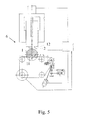
- Fig. 5 shows a wire cutting device 6 for cutting the single-crystal workpiece 1.
- the workpiece 1 is glued on a holding means 2 which is mounted to the cutting device 6.
- a multiple wire arrangement 11 is operated to cut the workpiece.
- the workpiece 1 is arranged below the holding means 2, and the wires 11 are guided from the bottom to the top of the workpiece 1.
- Fig. 6 shows a plate-like holding means 2 comprising a mounting surface 4 for mounting the holding means 2 on a processing device 6, e.g. the wire cutting device of Fig. 5 .
- the holding means 2 On the opposite side, the holding means 2 has holding surfaces 3 for receiving two single-crystal workpieces 1. The holding surfaces 3 fittingly match with the respective workpiece surface 5 to be glued to it.
- the holding means 2 can be made of any material, preferably a material that can be machined easily such as plastic, and preferably fiber reinforced plastic.
- a holding surface 3 is individually formed in dependence of the crystal orientation of the workpiece 1 with respect to its workpiece surface 5, which is glued to the holding surface 3.
- the holding surface 3 receives that workpiece 1 and thus ascertains the crystal orientation of the workpiece 1 with respect to the mounting surface 4 of the holding means 2.
- the workpiece surface 5 abuts against the holding surface 3, thus defining an exact orientation.
- the two holding surfaces 3 have different orientation with respect to the mounting surface 4. This accounts for two different workpieces 1, having different mismatch between crystal and mechanical orientation.
- the dashed lines in Fig. 6 denote to the bottom lines of the holding surfaces 3.
- the invention is described here in relation to cylindrical workpieces.
- the inventive idea may apply to any workpiece shape, especially rectangular shapes, such as with Silicon bricks.
- Fig. 7 shows a holding means 2 with three different workpieces 1 mounted on it.
- the crystal orientation with respect to the mechanical axis is different for each workpiece 1, as can be seen by the dashed top lines of the cores.
- the holding surfaces 3 formed in the holding means 2 have different shape and orientation.
- the crystal orientation of all workpieces 1 with respect to the reference surface 4 is the same as indicated by the dashed line and the arrows lying on that dashed line.
- the mounting surface 4 is fixed to a mounting support 12, e.g. a mounting plate, for mounting the assembly within a processing device 6 ( Fig. 5 ). It would be also possible that the mounting surface 4 of the holding means 2 is directly mounted to the processing device 6. It is not necessary that the mounting surface 4 is flat as in Fig. 6 . Embodiments having mounting surfaces of any other shape may be used. Also multiple mounting surfaces are possible.
- the mounting surface 4 may be e.g. comprised of mounting notches or any other means for being (directly or indirectly) attached to the machine tool.
- the holding means 2 is usually glued to the mounting plate 12.
- the glue used is typically a two-component epoxy resin which loses its adhesive power when heated to a temperature above 70 degrees C. After the cutting step, the mounting support 12 with the holding means 2 is placed in hot water to demount the holding means 2. The mounting support 12 can be reused.
- Fig. 8 shows the step of measuring the crystal orientation of the workpiece 1 with respect to its outer surface by means of X-ray diffraction.
- An X-ray source 13 directs an X-ray beam to the workpiece 1.
- the diffracted beam is measured with a detector 14.
- the obtained data allow the determination of the crystal orientation.
- a holding surface 3 is formed on the holding means 2 in dependence of the crystal orientation of said single-crystal workpiece 1 with respect to its workpiece surface 5.
- this step is performed by means of a programmable processing machine 9, preferably a milling machine.
- the data relating to the crystal and mechanical orientation and shape of the workpiece 1 are fed into the forming machine 9 before the forming step.
- a 3-dimensional holding surface 3 is modeled from that data and transferred to the raw material of the holding means 2.
- the drill of the milling machine 9 is movable in all three spatial directions.
- a 3-dimensional gluing mould results from a raw holding plate 2 (see Fig. 6 ).
- the holding surface 3 (or multiple holding surfaces 3) is (are) completed on the holding means 2, the workpieces 1 are glued with their workpiece surface 5 to the respective holding surface 3.
- the workpiece 1 is uniformly pressed against the holding surface 3 which is covered with glue.
- the shape and orientation of the holding surface 3 defines the crystal orientation of the individual workpiece 1 with respect to the reference surface 4.
- the workpieces 1 may be pressed onto the holding means 2.
- Fig. 10 shows, in a cross-sectional view, a preferred embodiment with the workpiece 1 being glued to the holding means 2 by means of a glue 16.
- a glue e.g. a two-component epoxy resin
- the holding surface 3 has recessions for receiving glue.
- the holding surface 3 is formed with multiple protrusions 7 extending towards the workpiece surface 5, in parallel to the surface 3.
- the protrusions 7 contact the workpiece surface 5 and the glue 16 is distributed in the space (recessions) between that protrusions 7.
- Such an embodiment allows an exact positioning of the workpiece 1, since the contact sites formed by the protrusions 7 exactly define the resulting crystal orientation of the workpiece 1. Deviations due to glue thickness and or shrinkage of the glue when curing may be avoided in such an embodiment.
- Fig. 11 shows another preferred embodiment with the holding surface 3 comprising at least one channel 8. Excessive glue 16 may escape through the channel 8.
- Fig. 12 shows an embodiment with a part of the workpiece surface 5 having flat shape. As already mentioned above, any shape of the workpiece surface is possible.
- the forming of the holding surface 3 is performed in dependence of the respective abutting workpiece surface 5.
- Fig. 13 and 14 show an assembly of a workpiece 1, glued on a holding means 2.
- the dashed and dotted lines indicate future cutting planes when mounted in a wire saw.
- the spacing between the workpieces 1 on a holding means 2 may be optimized towards the wire pitch. Meaning that if no attention is paid to the spacing, the wire cutting of the first and last wafer of a workpiece may not reveal a usable wafer (see Fig. 13 ). In Fig. 14 the cuts along the dashed lines results in five proper wafers. Cuts along the dotted lines result in six proper wafers.
- Fixation in lateral direction In order to obtain the advantage described above, the core needs to be fixated in the lateral direction (from left to right in the above drawings). This may be done by forming a stop 10 e.g. defining a surface (see arrow) where the core abuts against.
- stop means 10 for fixing the core in lateral direction may be provided as well: a clamp, rubber bands, glue that hardens (melt glue) or cures (instant glue, hard plaster) very rapidly, etc.
- a method of correction of wire saw imperfections may be applied as well. Any error in the cutting properties of the wire saw can be measured and corrected. In an initial measurement, the exact orientation of the cutting plane can be determined and the deviation from the theoretical plane can be used to align the cores perfectly with the true cutting plane.
- a flat see Fig. 12
- notch indentation parallel to the mechanical axis of the core
- the holding surface may be made such as to receive this flat or notch and thus determine the orientation of the core.
- the invention is not restricted to the embodiments described above.
- the application area is not limited to sapphire crystals.
- the invention may be applied to any other type of crystal to be processed (cutting, milling, drilling, grinding, etc.). Among them are various semiconductor crystals, silicon crystals for electronic devices or solar cell applications, etc..
- inventive method and holding means can be used for all kind of machines such as drills, polishing machines, grinders, etc.
- This invention and the following claims cover also a method and a holding means (2) wherein the holding means (2) is not formed/machined after the measurement of the crystal orientation of the workpiece (1) but wherein a set of different holding means are provided in order to allow a user to select the right holding means (2) with an individual holding surface (3) for an individual workpiece (1).
- Such a holding means (2) could be made from prefabricated plastic material.
- the Invention covers also semi finished holding means (2) which have a soft upper part which hardens out after a press form cylinder pressed the required form into said part, wherein said cylinder has the shape of a crystal work piece (1) and wherein the orientation of the cylinder when being pressed into the soft upper part is (eventually automatically) controlled in dependence from the crystal orientation of the workpiece (1).
Landscapes
- Engineering & Computer Science (AREA)
- Mechanical Engineering (AREA)
- Processing Of Stones Or Stones Resemblance Materials (AREA)
- Mechanical Treatment Of Semiconductor (AREA)
- Crystals, And After-Treatments Of Crystals (AREA)
Abstract
The invention relates to a method for fixing a single-crystal workpiece (1) on a holding means (2), the holding means (2) comprising a mounting surface (4) for mounting the holding means (2) on a processing device (6);
wherein the method comprising the steps of:
- measuring the crystal orientation of said single-crystal workpiece (1) with respect to a workpiece surface (5),
- forming, in dependence of the crystal orientation of said single-crystal workpiece (1) with respect to said workpiece surface (5), on the holding means (2) a holding surface (3) for abuttingly receiving said workpiece surface (5), thereby defining the crystal orientation of the single-crystal workpiece (1) with respect to the mounting surface (4) of the holding means (2), and
- gluing said workpiece surface (5) to said holding surface (3).
Description
- The invention relates to a method for fixing a single-crystal workpiece on a holding means, the holding means comprising a mounting surface for mounting the holding means on a processing device, e.g. a cutting device so that the single-crystal workpiece can be treated on said processing device in a precise manner.
- In particular, the invention relates to the cutting of crystalline materials, e.g. sapphire crystals, crystals containing silicon or boron, etc.. In wafer technology, single-crystal workpieces (usually denoted as ingots, boules or cores) are cut into thin slices for further processing.
- When a sapphire crystal is grown, one obtains a boule: a single-crystal ingot produced by synthetic means. The crystal orientation of the boule is determined by X-ray diffraction. Once the crystal orientation and a 3D model of the outer surface of the boule has been made, cores (cylinders) are drilled out from the boule with a hollow drill in accordance with the determined orientation. After the drilling process, the cores are ground or polished. Unfortunately, the true angle between the mechanical (geometrical) axis of the core and the orientation of the crystal axis normally does however not lie within the required tolerances.
- When cutting crystalline materials with a wire saw, the angle between the cutting plane and the planes of the crystal structure can be an extremely important and crucial parameter. Choosing the wrong orientation may result in the sawing wires being pushed aside, resulting in a curved cut. Especially for sapphire which is used for epitaxial growth of silicon, the cutting plane has to be very flat. It was found that the cuts are ideally made in an offset angle of 0° to 0,35° to the M-plane and 0° to 0,2° to the A-plane of the sapphire crystal.
- Sapphire is a crystalline material with the chemical formula Al2O3, i.e. aluminum oxide or alumina. Sapphire is cut around (not necessarily perfectly parallel to) the C-planes for epitaxial growth of materials used for LED's.
- The cores are glued to a holding means, also called sacrificial plate, that is in turn glued to a carrier plate. During the cutting process the usual positioning is as follows: the crystal is below and the holding means is on top. During the cutting process, the sawing wires bend in a bow-like manner. This means that at the end of the cutting process the sacrificial plate is cut by the sawing wires, hence its name. Thus, a holding means in form of a holding plate can be used only once.
- As already mentioned above, one of the sapphire's areas of application is in epitaxy, in particular for the production of LEDs (light emitting diodes). Epitaxy refers to the method of depositing a monocrystalline film on a monocrystalline substrate. The deposited film is denoted as epitaxial film or epitaxial layer. Epitaxial films may be grown from gaseous or liquid precursors. Because the substrate acts as a seed crystal, the deposited film takes on a lattice structure and orientation identical to those of the substrate. This is different from other thin-film deposition methods, which deposit polycrystalline or amorphous films, even on single-crystal substrates. If a film is deposited on a substrate of the same composition, the process is called homoepitaxy; otherwise it is called heteroepitaxy.
- In LED and semiconductor technology, sapphire is used as a substrate for the growth of epitaxial films, e.g. from silicon, GaN and/or GaInN. For the growth of epitaxial films, which are free from defects, it is vital to have an exact match between the surface orientation of the substrate and its respective crystal planes. Thus, the cutting of the sapphire core into multiple wafers is performed parallel to the crystal planes. However slight deviations in a particular angle/orientation from the crystal planes may be desirable to optimize the cutting performance. The desired orientation of the cutting plane with respect to the crystal orientation also depends on the substrate-film combination.
- In the following some known methods are described for orienting the ingot prior to the cutting process.
- Grinding a plane surface parallel to the long axis of a core or ingot marks a certain direction. When the ingot is cut, the wafer will show that mark of a missing segment along the circumference.
- For flat-face grinding an ingot is mounted into a holder, so that the main axis runs horizontal. For so called C-type ingots, the main axis is the C-direction (
Fig.4 ). The flat direction for C-type wafers is usually the A-direction. Therefore, in an initial step, the A-direction is marked. The ingot is then mounted into the holder, such that the marked direction points upwards. - In this position, measurements are taken and the ingot is adjusted for the desired flat-direction. The ingot mounted in the holder is sent to the grinding machine and returned for re-checking. If the marked direction is not within the desired precision, the adjustment may be corrected and the grinding step repeated. When using corrections for the systematic deviation of individual grinding machines, the number of correction steps can be minimized.
- The above method is characterized by the fact that for a correct alignment of the ingot in a saw, the surface of the ingot is formed by the use of grinding machines correspondingly.
- In a further state of the art it is known to glue the sapphire core to a holding plate. In order to correct any misalignment of the crystal axis and the mechanical axis of the core, the core and the holding plate are glued together under an angle. In a first step, glue is applied to the holding plate. Then, the core is held under an angle relative to that core and the exact angle is measured. Prior to gluing, the misalignment between the crystal axis and the mechanical axis of the core is measured by means of X-ray diffraction. The angle between the mechanical axis of the core and the holding plate is measured. This angle is corrected as long as the crystal axis of the core is at the desired angle with respect to the holding plate. Now, the glue is given time to cure. Due to the angle between holding plate and core, there are regions with different glue thickness.
- The above method is characterized by the fact that by try and error the gluing step is used for a correct alignment of the ingot in a saw.
- Another known method is based on the orientated stacking of cores. Cores are typically smaller than 300 mm, so that more than one core fits into a sawing device. Stacking machines (such as produced by EFG Berlin) are used that are designed for building larger assemblies of individually and consistently orientated cores. Assemblies are then glued to a suitable support for the sawing device and sliced as a whole.
- The stacking process begins with the marking of the reference direction, which typically is the A-direction for the C-type crystals. In the marked direction, plastic beams are glued to the core in order to provide a sufficiently large attachment surface for subsequent gluing.
- Cores with plastic beams are mounted in an adjustment holder, and the holder is attached to a turnable plate. Measurements are then made and the desired orientation is adjusted. Thereafter a new stage is used for another core.
- Each stage consists of a ring and an adapter for ingots of various sizes from 2" to 10". 12" ingots are mounted without an adapter. For the adjustment of the ingot orientation, there are two sets of screws for each stage. The orientation variation range is in the order of 1-1,5°.
- Epoxy resin is usually used to glue the specimens to the support/holding plate. After curing of the resin, the stacking units can be disassembled. The resulting assembly can then be mounted in a wire saw for cutting the wafers.
- The above method is characterized by the fact that by a mechanical adjustment holder which is removed after adjusting positioning the gluing process is performed for a correct alignment of the ingot in a saw.
- The following disadvantages have to be considered for this prior art. The core (or ingot) has to be positioned very accurately to the holding plate which is difficult (requires a huge apparatus used by EFG) and cumbersome (the position has to be altered by screws or the like means). The desired position has to be fixed while the glue is curing. This means that the positioning means for positioning the cores cannot be used as long as the glue has not cured. The cores cannot be positioned by using robot arms, because they cannot hold a position for such a long time. They have to readjust their position consistently, rendering them unsuitable for gluing.
- The object of the invention is to provide a new method for fixing at least one single-crystal workpiece to a holding means, the method allowing an accurate positioning of the workpiece with respect to the holding means. The method shall do without positioning means/adjustment holders known from prior art. The method shall be reliable, time-saving and cost-effective and shall provide a strong assembly of the workpiece and the holding means. The assembly shall exactly define the crystal orientation of the workpiece with respect to a processing machine.
- This object is achieved by a method as given in the pre-characterizing part of
claim 1 and the following steps: - measuring the crystal orientation of said single-crystal workpiece with respect to a workpiece surface,
- in dependence of the crystal orientation of said single-crystal workpiece with respect to said workpiece surface, forming on the holding means a holding surface for abuttingly receiving said workpiece surface, thereby defining the crystal orientation of the single-crystal workpiece with respect to the mounting surface of the holding means, and
- gluing said workpiece surface to said holding surface.
- The holding surface is formed such, that a desired (or pre-specified) crystal orientation with respect to the mounting surface is achieved. The holding surface then ascertains the crystal orientation of the single-crystal workpiece with respect to the mounting surface, when the workpiece fittingly abuts against the holding surface.
- According to the inventive solution, a holding surface is formed on the holding means for receiving the outer surface of the core. Now, the core can be placed on the holding means such that its surface engages with the holding surface on the holding means and the core can be glued to the holding means without mechanical aids securing the angle between the holding means and the crystal axis of the core. The holding surface on the holding means is formed in such a way that, when the core is placed on it and abuttingly engages on it, the crystal axis extends in the desired direction.
- In contrast to prior art, the holding means is formed or adapted, respectively, which is much easier, time-saving and cost-effective than adapting the ingot or using complicated positioning means. The advantage of the invention consists in the simplicity and effectiveness of the holding means, which does not require any additional positioning means when fixing the workpiece. Due to the fact that the holding surface has already the "correct" orientation within the holding means, the workpiece just has to be placed on the holding surface. The term "correct" orientation refers to an orientaion, resulting in the desired crystal orientation with respect to the mounting surface, when the workpiece abuts against the holding surface.
- With the inventive method, only the holding surface of the holding means has to be machined according to the deviation of the crystal axis from the mechanical axis of the workpiece. In the case of a cylindrical workpiece, e.g. a sapphire core, the cylinder axis or the lateral workpiece surface may be used as geometrical reference orientation. In general, the workpiece surface to be received by the holding surface of the holding means serves as geometrical reference surface.
- The holding surface can be formed automatically using known CAD/CAM programmable machine tools, such as a milling machine.
- The inventive method is reduced to the steps of measuring the angle between the crystal axis and a workpiece surface, machining a holding surface on a holding means correspondingly to a workpiece surface and gluing the workpiece surface to the holding surface.
- It is preferred that data relating to the measured crystal orientation of said single-crystal workpiece with respect to said workpiece surface are fed to a programmable forming machine before forming said holding surface on said holding means. This allows an easy and automatical machining of the holding surfaces.
- The single-crystal workpiece may be an ingot, a boule, a pre-grinded or pre-cut single crystal, a core with cylindrical shape or a single-crystal specimen of any other shape and geometry.
- It is of course possible to fix not only one but multiple cores to one holding means. The cores are selected, their crystal orientation is defined, the off-plane orientation and tilt is determined, and their geometrical parameters are measured (in the case of a cylinder in length and in diameter). The core data and orientation corrections are programmed into a milling machine. Pockets for each core are milled into the holding means with the desired offset and tilt. Finally, the cores are glued into the pockets which are defined by the holding surfaces.
- The slicing is then done in the correct offset and tilt. The assembly of the workpieces glued on the holding means can be positioned manually, semiautomatically or automatically in a machine tool such as a wire saw, a milling, drilling or grinding device, etc..
- In order to define a volume for the glue between the core and the holding surface, at least one recession may be formed in the holding surface adjacent to the workpiece surface. This can be done by forming protrusions on the holding surface or by forming depressions in the holding surface. In either way, the amount of glue applied to the holding surface can be exactly dosed to fill this volume. By this the workpiece lies against the protrusions without glue as intermediate layer. This makes the positioning even more precise, since no positioning error is introduced by the glue. Channels in the holding surface may be provided to let the glue escape if more glue is applied than there is space for in the volume between the protrusions.
- The holding means may be mounted directly in the machine tool, such as a wire saw. Alternatively, the holding means can be glued to an additional mounting support, e.g. a mounting plate (also called carrier plate). Since the cutting wires do not cut the mounting support (and the mounting support has not to be machined for each workpiece individually), this support can be made of more robust materials, such as steel. An additional intermediate plate between the holding means and the mounting support may be used to adjust for a special mounting support. An intermediate plate is not necessary and is usually used only if the mounting support is heavy or expensive or in order to have a simpler gluing plate. This intermediate plate may then be screwed to the mounting support.
- Multiple cores can be glued to one plate. Since all the cores do not have the same mismatch, multiple holding surfaces may be used.
- Further embodiments of the invention are indicated in the figures and in the dependent claims.
- The list of reference marks forms part of the disclosure.
- The invention will now be explained in detail by the drawings. In the drawings:
-
Fig. 1 shows a single-crystal ingot with cores taken from it by means of a hollow drill. -
Fig. 2 shows a single-crystal core, -
Fig. 3 shows the A- and M-planes of the sapphire-crystal structure, -
Fig. 4 shows the C- and R-planes of the sapphire-crystal structure, -
Fig. 5 shows a wire cutting device with a workpiece mounted on a holding means, -
Fig. 6 shows an inventive holding means with two holding surfaces, -
Fig. 7 shows an inventive holding means with three workpieces mounted thereon, -
Fig. 8 shows schematically an x-ray diffraction device with a workpiece, -
Fig. 9 shows a forming machine for forming the holding surface, -
Fig. 10, 11 and12 show, in a cross-sectional view, the workpiece glued on the holding means, and -
Fig. 13 and 14 show a workpiece glued on the holding means with indicated cutting planes. - In the following, the invention will be described in relation to a sapphire workpiece, but the ideas can be applied to any other crystals as well (such as e.g. containing Bor or Silicon).
-
Fig. 1 shows a sapphire ingot orboule 15 as being pulled out of the melt. During pulling out, the ingot is slowly rotated. This process is also known as Czochralski process. Normally however, the Kyropulous process is used, where a cold rod is immersed into the melt and the crystalization process starts at the end of the rod, while the melt surrounding the rod slowly cools down. - The 3-dimensional outer surface of the ingot is modeled, and the crystal orientation is measured with respect to the outer surface. Once the crystal orientation and the 3D model of the outer surface of the boule has been made, cores are drilled out from the boule with a hollow drill.
Fig. 1 shows the resulting holes in theingot 15. The direction of drilling is chosen with respect to the crystal orientation of theingot 15, in order to obtain cylinders with their geometrical axis matching a certain crystal axis. Unfortunately, in most cases there is a deviation of the crystal axis from the mechanical axis of the core and the orientation of the crystal axis normally does not lie within the required tolerances. -
Fig. 2 shows a single-crystal workpiece 1 of cylindrical shape as being drilled out of theingot 15. Aworkpiece surface 5 is indicated for being glued on the holding means. -
Fig. 3 andFig. 4 show without the atomic arrangement the crystal structure of sapphire. InFig. 3 the so-called A- and M-planes and the A- and M-axis, which run perpendicular to the respective planes, are indicated.Fig. 4 shows the C- and R-planes as well as the corresponding C- and R-axis of the crystal structure. It was found that the cut is ideally made in an offset angle of 0°to 0,35° to the M-plane and 0°to 0,2° to the A-plane of the sapphire crystal. - However, any other desired direction (including off-plane directions) may be exactly adjusted by the inventive method. Depending on the type of crystal and its application, appropriate cutting planes (and their exact deviation from the crystal planes) may be chosen.
-
Fig. 5 shows awire cutting device 6 for cutting the single-crystal workpiece 1. Theworkpiece 1 is glued on a holding means 2 which is mounted to thecutting device 6. Amultiple wire arrangement 11 is operated to cut the workpiece. Usually theworkpiece 1 is arranged below the holding means 2, and thewires 11 are guided from the bottom to the top of theworkpiece 1. -
Fig. 6 shows a plate-like holding means 2 comprising a mountingsurface 4 for mounting the holding means 2 on aprocessing device 6, e.g. the wire cutting device ofFig. 5 . On the opposite side, the holding means 2 has holdingsurfaces 3 for receiving two single-crystal workpieces 1. The holding surfaces 3 fittingly match with therespective workpiece surface 5 to be glued to it. - The holding means 2 can be made of any material, preferably a material that can be machined easily such as plastic, and preferably fiber reinforced plastic.
- For each
workpiece 1, a holdingsurface 3 is individually formed in dependence of the crystal orientation of theworkpiece 1 with respect to itsworkpiece surface 5, which is glued to the holdingsurface 3. The holdingsurface 3 receives thatworkpiece 1 and thus ascertains the crystal orientation of theworkpiece 1 with respect to the mountingsurface 4 of the holding means 2. When theworkpiece 1 is placed in the holdingsurface 3, theworkpiece surface 5 abuts against the holdingsurface 3, thus defining an exact orientation. - As can be seen from
Fig. 6 , the two holdingsurfaces 3 have different orientation with respect to the mountingsurface 4. This accounts for twodifferent workpieces 1, having different mismatch between crystal and mechanical orientation. The dashed lines inFig. 6 denote to the bottom lines of the holding surfaces 3. - The invention is described here in relation to cylindrical workpieces. However, the inventive idea may apply to any workpiece shape, especially rectangular shapes, such as with Silicon bricks.
-
Fig. 7 shows a holding means 2 with threedifferent workpieces 1 mounted on it. The crystal orientation with respect to the mechanical axis is different for eachworkpiece 1, as can be seen by the dashed top lines of the cores. Correspondingly, the holdingsurfaces 3 formed in the holding means 2 have different shape and orientation. However, the crystal orientation of allworkpieces 1 with respect to thereference surface 4 is the same as indicated by the dashed line and the arrows lying on that dashed line. - The mounting
surface 4 is fixed to a mountingsupport 12, e.g. a mounting plate, for mounting the assembly within a processing device 6 (Fig. 5 ). It would be also possible that the mountingsurface 4 of the holding means 2 is directly mounted to theprocessing device 6. It is not necessary that the mountingsurface 4 is flat as inFig. 6 . Embodiments having mounting surfaces of any other shape may be used. Also multiple mounting surfaces are possible. The mountingsurface 4 may be e.g. comprised of mounting notches or any other means for being (directly or indirectly) attached to the machine tool. - The holding means 2 is usually glued to the mounting
plate 12. The glue used is typically a two-component epoxy resin which loses its adhesive power when heated to a temperature above 70 degrees C. After the cutting step, the mountingsupport 12 with the holding means 2 is placed in hot water to demount the holding means 2. The mountingsupport 12 can be reused. - In the following, the method for positioning and fixing the
workpiece 1 on a holding means 2 is described in detail.Fig. 8 shows the step of measuring the crystal orientation of theworkpiece 1 with respect to its outer surface by means of X-ray diffraction. AnX-ray source 13 directs an X-ray beam to theworkpiece 1. The diffracted beam is measured with adetector 14. The obtained data allow the determination of the crystal orientation. - In a next step, a holding
surface 3 is formed on the holding means 2 in dependence of the crystal orientation of said single-crystal workpiece 1 with respect to itsworkpiece surface 5. In the embodiment ofFig. 9 , this step is performed by means of aprogrammable processing machine 9, preferably a milling machine. The data relating to the crystal and mechanical orientation and shape of theworkpiece 1 are fed into the formingmachine 9 before the forming step. A 3-dimensional holding surface 3 is modeled from that data and transferred to the raw material of the holding means 2. As indicated by the 3-dimensional coordinate system ofFig. 9 , the drill of themilling machine 9 is movable in all three spatial directions. During the forming step, a 3-dimensional gluing mould results from a raw holding plate 2 (seeFig. 6 ). - When the holding surface 3 (or multiple holding surfaces 3) is (are) completed on the holding means 2, the
workpieces 1 are glued with theirworkpiece surface 5 to therespective holding surface 3. Theworkpiece 1 is uniformly pressed against the holdingsurface 3 which is covered with glue. The shape and orientation of the holdingsurface 3 defines the crystal orientation of theindividual workpiece 1 with respect to thereference surface 4. - During curing of the glue, the
workpieces 1 may be pressed onto the holding means 2. -
Fig. 10 shows, in a cross-sectional view, a preferred embodiment with theworkpiece 1 being glued to the holding means 2 by means of aglue 16. Preferably, an epoxy glue, e.g. a two-component epoxy resin, is used, however, any other type of glue may be also used. The holdingsurface 3 has recessions for receiving glue. In the embodiment ofFig. 10 the holdingsurface 3 is formed withmultiple protrusions 7 extending towards theworkpiece surface 5, in parallel to thesurface 3. Theprotrusions 7 contact theworkpiece surface 5 and theglue 16 is distributed in the space (recessions) between thatprotrusions 7. Such an embodiment allows an exact positioning of theworkpiece 1, since the contact sites formed by theprotrusions 7 exactly define the resulting crystal orientation of theworkpiece 1. Deviations due to glue thickness and or shrinkage of the glue when curing may be avoided in such an embodiment. -
Fig. 11 shows another preferred embodiment with the holdingsurface 3 comprising at least onechannel 8.Excessive glue 16 may escape through thechannel 8. -
Fig. 12 shows an embodiment with a part of theworkpiece surface 5 having flat shape. As already mentioned above, any shape of the workpiece surface is possible. The forming of the holdingsurface 3 is performed in dependence of the respective abuttingworkpiece surface 5. -
Fig. 13 and 14 show an assembly of aworkpiece 1, glued on a holding means 2. The dashed and dotted lines indicate future cutting planes when mounted in a wire saw. - In the following, a method of optimization of the pitch of the cutting wires is described. The spacing between the
workpieces 1 on a holding means 2 may be optimized towards the wire pitch. Meaning that if no attention is paid to the spacing, the wire cutting of the first and last wafer of a workpiece may not reveal a usable wafer (seeFig. 13 ). InFig. 14 the cuts along the dashed lines results in five proper wafers. Cuts along the dotted lines result in six proper wafers. - Clearly, the position of a second core can be optimized in the same manner.
- Fixation in lateral direction: In order to obtain the advantage described above, the core needs to be fixated in the lateral direction (from left to right in the above drawings). This may be done by forming a
stop 10 e.g. defining a surface (see arrow) where the core abuts against. - Other stop means 10 for fixing the core in lateral direction may be provided as well: a clamp, rubber bands, glue that hardens (melt glue) or cures (instant glue, hard plaster) very rapidly, etc.
- A method of correction of wire saw imperfections may be applied as well. Any error in the cutting properties of the wire saw can be measured and corrected. In an initial measurement, the exact orientation of the cutting plane can be determined and the deviation from the theoretical plane can be used to align the cores perfectly with the true cutting plane.
- If the core has a rotational symmetry (which is usually the case), a flat (see
Fig. 12 ) or notch (indentation parallel to the mechanical axis of the core) may be provided on the core. The holding surface may be made such as to receive this flat or notch and thus determine the orientation of the core. - The invention is not restricted to the embodiments described above. In particular, the application area is not limited to sapphire crystals. The invention may be applied to any other type of crystal to be processed (cutting, milling, drilling, grinding, etc.). Among them are various semiconductor crystals, silicon crystals for electronic devices or solar cell applications, etc..
- It is clear that the inventive method and holding means can be used for all kind of machines such as drills, polishing machines, grinders, etc.
This invention and the following claims cover also a method and a holding means (2) wherein the holding means (2) is not formed/machined after the measurement of the crystal orientation of the workpiece (1) but wherein a set of different holding means are provided in order to allow a user to select the right holding means (2) with an individual holding surface (3) for an individual workpiece (1). - Such a holding means (2) could be made from prefabricated plastic material.
- The Invention covers also semi finished holding means (2) which have a soft upper part which hardens out after a press form cylinder pressed the required form into said part, wherein said cylinder has the shape of a crystal work piece (1) and wherein the orientation of the cylinder when being pressed into the soft upper part is (eventually automatically) controlled in dependence from the crystal orientation of the workpiece (1).
-
- 1 -
- single-crystal workpiece
- 2 -
- holding means
- 3 -
- holding surface
- 4 -
- mounting surface
- 5 -
- workpiece surface
- 6 -
- processing device
- 7 -
- protrusion
- 8 -
- channel
- 9 -
- forming machine
- 10 -
- stop
- 11 -
- sawing wire of a cutting device
- 12 -
- mounting plate
- 13 -
- X-ray tube
- 14 -
- detector
- 15 -
- ingot
- 16 -
- glue
Claims (15)
- Method for fixing a single-crystal workpiece (1) on a holding means (2), the holding means (2) comprising a mounting surface (4) for mounting the holding means (2) in a defined orientation on a processing device (6);
wherein the method comprising the steps of:- measuring the crystal orientation of said single-crystal workpiece (1) with respect to a workpiece surface (5) of said workpiece (1),- in dependence of the individual crystal orientation of said single-crystal workpiece (1) with respect to said workpiece surface (5), forming on the holding means (2) a holding surface (3) for abuttingly receiving said workpiece surface (5), thereby defining the crystal orientation of the single-crystal workpiece (1) with respect to the mounting surface (4) of the holding means (2), and- gluing said workpiece surface (5) to said holding surface (3). - The method according to claim 1, wherein the step of forming said holding surface (3) is done by a programmable forming machine (9), preferably a milling machine.
- The method according to claim 2, wherein data relating to the measured crystal orientation of said single-crystal workpiece (1) with respect to said workpiece surface (5) are fed to the programmable forming machine (9) before forming said holding surface (3) on said holding means (2).
- The method according to any of the preceding claims, wherein at least one recession is formed in said holding surface (3) for receiving glue.
- The method according to any of the preceding claims, wherein at least one channel (8) is formed in said holding surface (3) for draining excessive glue.
- The method according to any of the preceding claims, wherein said holding surface (3) has a stop (10) for positioning the single-crystal workpiece (1) on the holding means (2).
- The method according to any of the preceding claims, wherein the holding means (2) is formed by a plate.
- The method according to any of the preceding claims, wherein the single-crystal workpiece (1) has a cylindrical shape and wherein the holding surface (3) is formed to receive the lateral surface of the single-crystal workpiece (1).
- The method according any of the preceding claims, wherein the single-crystal workpiece (1) is a sapphire.
- The method according to any of the preceding claims,
wherein multiple single-crystal workpieces (1) are fixed on a holding means (2) and the crystal orientation of each single-crystal workpiece (1) is measured with respect to one of its workpiece surfaces (5), and comprising the steps of:- forming for each single-crystal workpiece (1), in dependence of its crystal orientation with respect to its workpiece surface (5), on the holding means (2) a separate holding surface (3) for abuttingly receiving the respective workpiece surface (5), thereby defining for all single-crystal workpieces (1) the same crystal orientation with respect to the mounting surface (4) of the holding means (2), and- gluing the workpiece surface (5) of each single-crystal workpiece (1) to the respective holding surface (3). - Method for cutting a single-crystal workpiece (1) into slices, wherein the method comprises the steps of any of the preceding claims and the steps of:- mounting the holding means (2) with the singe-crystal workpiece (1) in a saw, and- sawing the single-crystal workpiece (1).
- Holding means (2) for fixing a single-crystal workpiece (1), the holding means (2) comprising:- a mounting surface (4) for mounting the holding means (2) in a defined orientation on a processing device (6),- a holding surface (3) for abuttingly receiving a workpiece surface (5) of the single-crystal workpiece (1) to be glued on the holding surface (3),
wherein said holding surface (3) is individually formed in dependence of the crystal orientation of said single-crystal workpiece (1) with respect to said workpiece surface (5), thereby defining the crystal orientation of the single-crystal workpiece (1) with respect to the mounting surface (4) of the holding means (2). - The holding means according to claim 12, wherein at least a recession is formed in said holding surface (3) for receiving glue and/or, wherein at least one channel (8) is formed in said holding surface (3) for draining excessive glue.
- The holding means according to any of the claims 12 to 13, wherein said holding surface (3) has a stop (10) for positioning the single-crystal workpiece (1) on the holding means (2).
- Set of a number of holding means (2) according to claim 12 with different oriented holding surfaces (3) for selection of an appropriate holding means (2) to be used in a method of claim 1.
Priority Applications (4)
| Application Number | Priority Date | Filing Date | Title |
|---|---|---|---|
| EP11165009A EP2520401A1 (en) | 2011-05-05 | 2011-05-05 | Method for fixing a single-crystal workpiece to be treated on a processing device |
| CN201280021612.8A CN103501975A (en) | 2011-05-05 | 2012-04-17 | Method for fixing a single-crystal workpiece to be treated on a processing device |
| PCT/IB2012/051927 WO2012150517A1 (en) | 2011-05-05 | 2012-04-17 | Method for fixing a single-crystal workpiece to be treated on a processing device |
| EP12720636.5A EP2704886A1 (en) | 2011-05-05 | 2012-04-17 | Method for fixing a single-crystal workpiece to be treated on a processing device |
Applications Claiming Priority (1)
| Application Number | Priority Date | Filing Date | Title |
|---|---|---|---|
| EP11165009A EP2520401A1 (en) | 2011-05-05 | 2011-05-05 | Method for fixing a single-crystal workpiece to be treated on a processing device |
Publications (1)
| Publication Number | Publication Date |
|---|---|
| EP2520401A1 true EP2520401A1 (en) | 2012-11-07 |
Family
ID=46062667
Family Applications (2)
| Application Number | Title | Priority Date | Filing Date |
|---|---|---|---|
| EP11165009A Withdrawn EP2520401A1 (en) | 2011-05-05 | 2011-05-05 | Method for fixing a single-crystal workpiece to be treated on a processing device |
| EP12720636.5A Withdrawn EP2704886A1 (en) | 2011-05-05 | 2012-04-17 | Method for fixing a single-crystal workpiece to be treated on a processing device |
Family Applications After (1)
| Application Number | Title | Priority Date | Filing Date |
|---|---|---|---|
| EP12720636.5A Withdrawn EP2704886A1 (en) | 2011-05-05 | 2012-04-17 | Method for fixing a single-crystal workpiece to be treated on a processing device |
Country Status (3)
| Country | Link |
|---|---|
| EP (2) | EP2520401A1 (en) |
| CN (1) | CN103501975A (en) |
| WO (1) | WO2012150517A1 (en) |
Cited By (5)
| Publication number | Priority date | Publication date | Assignee | Title |
|---|---|---|---|---|
| CN107096634A (en) * | 2016-02-23 | 2017-08-29 | 内蒙古盾安光伏科技有限公司 | Polysilicon particle platform and particle method |
| CN107639755A (en) * | 2017-09-26 | 2018-01-30 | 深圳市石金科技股份有限公司 | A kind of processing method and its special fixture of graphite vanes pump blade |
| US10052848B2 (en) | 2012-03-06 | 2018-08-21 | Apple Inc. | Sapphire laminates |
| US10324496B2 (en) | 2013-12-11 | 2019-06-18 | Apple Inc. | Cover glass arrangement for an electronic device |
| US10406634B2 (en) | 2015-07-01 | 2019-09-10 | Apple Inc. | Enhancing strength in laser cutting of ceramic components |
Families Citing this family (4)
| Publication number | Priority date | Publication date | Assignee | Title |
|---|---|---|---|---|
| JP6132621B2 (en) * | 2013-03-29 | 2017-05-24 | Sumco Techxiv株式会社 | Method for slicing semiconductor single crystal ingot |
| JP6173225B2 (en) * | 2014-01-16 | 2017-08-02 | 京セラ株式会社 | Cutting plate |
| CN113696358B (en) * | 2021-08-26 | 2023-04-07 | 西安中晶半导体材料有限公司 | Multi-wire cutting method for realizing single crystal with deviated crystal orientation |
| EP4289582A1 (en) * | 2022-06-10 | 2023-12-13 | Scientific Visual SA | Crystal wafering system and method |
Citations (10)
| Publication number | Priority date | Publication date | Assignee | Title |
|---|---|---|---|---|
| DE2752925A1 (en) * | 1977-11-26 | 1979-05-31 | Philips Patentverwaltung | Monocrystal alignment and securing equipment suspends in mounting above base aligned with chamber support axis |
| US4819387A (en) * | 1987-12-16 | 1989-04-11 | Motorola, Inc. | Method of slicing semiconductor crystal |
| US5720271A (en) * | 1995-04-22 | 1998-02-24 | Hauser; Charles | Process for the orientation of single crystals for cutting in a cutting machine and device for practicing this process |
| US5839424A (en) * | 1996-04-16 | 1998-11-24 | Hct Shaping System Sa | Process for the orientation of several single crystals disposed side by side on a cutting support for their simultaneous cutting in a cutting machine and device for practicing this process |
| JPH10337695A (en) * | 1997-06-03 | 1998-12-22 | Shin Etsu Handotai Co Ltd | Adhering method and slicing method of semiconductor single crystal ingot |
| US20040084042A1 (en) * | 2002-11-06 | 2004-05-06 | Seh America, Inc. | Apparatus, system and method for cutting a crystal ingot |
| EP1568457A1 (en) * | 2001-06-13 | 2005-08-31 | Freiberger Compound Materials GmbH | Device and method for determining the orientation of a crystallographic plane in relation to a crystal surface |
| US20060032430A1 (en) * | 2004-08-10 | 2006-02-16 | Efg Elektrotechnische Fabrikations-Und Grosshandelsgesellschaft Mbh | Method and apparatus for the measurement, orientation and fixation of at least one single crystal |
| JP2007118354A (en) * | 2005-10-27 | 2007-05-17 | Kyocera Corp | Jig for supporting ingot |
| WO2009028756A1 (en) * | 2007-08-24 | 2009-03-05 | Dow Beam Co., Ltd. | Supporting plate for slicing silicon ingot |
Family Cites Families (2)
| Publication number | Priority date | Publication date | Assignee | Title |
|---|---|---|---|---|
| CN101216440B (en) * | 2008-01-09 | 2010-11-10 | 北京钢研高纳科技股份有限公司 | Oriented Silicon Steel [001] crystal orientation deviation angle alpha, beta determination method |
| DE102008051673B4 (en) * | 2008-10-15 | 2014-04-03 | Siltronic Ag | A method for simultaneously separating a composite rod of silicon into a plurality of disks |
-
2011
- 2011-05-05 EP EP11165009A patent/EP2520401A1/en not_active Withdrawn
-
2012
- 2012-04-17 WO PCT/IB2012/051927 patent/WO2012150517A1/en active Application Filing
- 2012-04-17 EP EP12720636.5A patent/EP2704886A1/en not_active Withdrawn
- 2012-04-17 CN CN201280021612.8A patent/CN103501975A/en active Pending
Patent Citations (10)
| Publication number | Priority date | Publication date | Assignee | Title |
|---|---|---|---|---|
| DE2752925A1 (en) * | 1977-11-26 | 1979-05-31 | Philips Patentverwaltung | Monocrystal alignment and securing equipment suspends in mounting above base aligned with chamber support axis |
| US4819387A (en) * | 1987-12-16 | 1989-04-11 | Motorola, Inc. | Method of slicing semiconductor crystal |
| US5720271A (en) * | 1995-04-22 | 1998-02-24 | Hauser; Charles | Process for the orientation of single crystals for cutting in a cutting machine and device for practicing this process |
| US5839424A (en) * | 1996-04-16 | 1998-11-24 | Hct Shaping System Sa | Process for the orientation of several single crystals disposed side by side on a cutting support for their simultaneous cutting in a cutting machine and device for practicing this process |
| JPH10337695A (en) * | 1997-06-03 | 1998-12-22 | Shin Etsu Handotai Co Ltd | Adhering method and slicing method of semiconductor single crystal ingot |
| EP1568457A1 (en) * | 2001-06-13 | 2005-08-31 | Freiberger Compound Materials GmbH | Device and method for determining the orientation of a crystallographic plane in relation to a crystal surface |
| US20040084042A1 (en) * | 2002-11-06 | 2004-05-06 | Seh America, Inc. | Apparatus, system and method for cutting a crystal ingot |
| US20060032430A1 (en) * | 2004-08-10 | 2006-02-16 | Efg Elektrotechnische Fabrikations-Und Grosshandelsgesellschaft Mbh | Method and apparatus for the measurement, orientation and fixation of at least one single crystal |
| JP2007118354A (en) * | 2005-10-27 | 2007-05-17 | Kyocera Corp | Jig for supporting ingot |
| WO2009028756A1 (en) * | 2007-08-24 | 2009-03-05 | Dow Beam Co., Ltd. | Supporting plate for slicing silicon ingot |
Cited By (7)
| Publication number | Priority date | Publication date | Assignee | Title |
|---|---|---|---|---|
| US10052848B2 (en) | 2012-03-06 | 2018-08-21 | Apple Inc. | Sapphire laminates |
| US10324496B2 (en) | 2013-12-11 | 2019-06-18 | Apple Inc. | Cover glass arrangement for an electronic device |
| US10386889B2 (en) | 2013-12-11 | 2019-08-20 | Apple Inc. | Cover glass for an electronic device |
| US10406634B2 (en) | 2015-07-01 | 2019-09-10 | Apple Inc. | Enhancing strength in laser cutting of ceramic components |
| CN107096634A (en) * | 2016-02-23 | 2017-08-29 | 内蒙古盾安光伏科技有限公司 | Polysilicon particle platform and particle method |
| CN107639755A (en) * | 2017-09-26 | 2018-01-30 | 深圳市石金科技股份有限公司 | A kind of processing method and its special fixture of graphite vanes pump blade |
| CN107639755B (en) * | 2017-09-26 | 2019-06-11 | 深圳市石金科技股份有限公司 | A kind of processing method of graphite vanes pump blade |
Also Published As
| Publication number | Publication date |
|---|---|
| CN103501975A (en) | 2014-01-08 |
| EP2704886A1 (en) | 2014-03-12 |
| WO2012150517A1 (en) | 2012-11-08 |
Similar Documents
| Publication | Publication Date | Title |
|---|---|---|
| EP2520401A1 (en) | Method for fixing a single-crystal workpiece to be treated on a processing device | |
| US5839424A (en) | Process for the orientation of several single crystals disposed side by side on a cutting support for their simultaneous cutting in a cutting machine and device for practicing this process | |
| RU2365905C2 (en) | Way and device for measurement, orientation and fixing of at least one monocrystal | |
| US5720271A (en) | Process for the orientation of single crystals for cutting in a cutting machine and device for practicing this process | |
| US8282761B2 (en) | Method for simultaneously cutting a compound rod of semiconductor material into a multiplicity of wafers | |
| CN110468447B (en) | Chamfered silicon carbide substrate and chamfering method | |
| SK4502003A3 (en) | Method and device for cutting single crystals, in addition to an adjusting device and a test method for determining a crystal orientation | |
| CN113427650B (en) | Method for measuring orientation of directionally solidified alloy single crystal and cutting seed crystal | |
| JP2024014982A (en) | SiC crystal substrate with lattice plane orientation optimal for crack reduction and its manufacturing method | |
| JP6923067B2 (en) | Semiconductor single crystal ingot slicing method | |
| CN200981169Y (en) | Oriented processing flat grinder | |
| CN108000291A (en) | Correct and use automatic orientation auxiliary device in sapphire ingot c faces | |
| CN108214955B (en) | A kind of directional cutting device and processing method for gallium nitride | |
| KR100526215B1 (en) | A Manufacturing Method And Device For Silicon Single Crystal Wafer | |
| JP2000143383A (en) | Production of compound semiconductor single crystal | |
| JPH06122119A (en) | Seed rod cutting method | |
| JP5922530B2 (en) | Orientation flat position determination method and orientation flat position determination apparatus | |
| WO2015047819A1 (en) | Method and apparatus for processing sapphire | |
| EP4289582A1 (en) | Crystal wafering system and method | |
| JP2016199002A (en) | Manufacturing method for columnar sapphire single crystal block and manufacturing apparatus for the same | |
| WO2023127454A1 (en) | Method for producing group iii nitride single crystal substrate and aluminum nitride single crystal substrate | |
| US20220025546A1 (en) | Sic crystals with an optimal orientation of lattice planes for fissure reduction and method of producing same | |
| JPH10119032A (en) | Matching method for crystal orientation in cutting of single crystal ingot having cleavability | |
| TWI809766B (en) | Manufacturing method of GaAs wafer and GaAs wafer group | |
| CN111801771B (en) | Method for slicing semiconductor single crystal ingot |
Legal Events
| Date | Code | Title | Description |
|---|---|---|---|
| PUAI | Public reference made under article 153(3) epc to a published international application that has entered the european phase |
Free format text: ORIGINAL CODE: 0009012 |
|
| AK | Designated contracting states |
Kind code of ref document: A1 Designated state(s): AL AT BE BG CH CY CZ DE DK EE ES FI FR GB GR HR HU IE IS IT LI LT LU LV MC MK MT NL NO PL PT RO RS SE SI SK SM TR |
|
| AX | Request for extension of the european patent |
Extension state: BA ME |
|
| STAA | Information on the status of an ep patent application or granted ep patent |
Free format text: STATUS: THE APPLICATION IS DEEMED TO BE WITHDRAWN |
|
| 18D | Application deemed to be withdrawn |
Effective date: 20130508 |