EP2520315B1 - Réacteur à structure de courroies-plaques métalliques - Google Patents
Réacteur à structure de courroies-plaques métalliques Download PDFInfo
- Publication number
- EP2520315B1 EP2520315B1 EP10840300.7A EP10840300A EP2520315B1 EP 2520315 B1 EP2520315 B1 EP 2520315B1 EP 10840300 A EP10840300 A EP 10840300A EP 2520315 B1 EP2520315 B1 EP 2520315B1
- Authority
- EP
- European Patent Office
- Prior art keywords
- metal
- discharge
- positive electrode
- housing
- reactor
- Prior art date
- Legal status (The legal status is an assumption and is not a legal conclusion. Google has not performed a legal analysis and makes no representation as to the accuracy of the status listed.)
- Active
Links
- 229910052751 metal Inorganic materials 0.000 title claims description 86
- 239000002184 metal Substances 0.000 title claims description 86
- 239000004020 conductor Substances 0.000 claims description 46
- 230000003449 preventive effect Effects 0.000 claims description 31
- GWEVSGVZZGPLCZ-UHFFFAOYSA-N Titan oxide Chemical compound O=[Ti]=O GWEVSGVZZGPLCZ-UHFFFAOYSA-N 0.000 claims description 23
- 238000009413 insulation Methods 0.000 claims description 23
- 239000010935 stainless steel Substances 0.000 claims description 22
- 229910001220 stainless steel Inorganic materials 0.000 claims description 22
- 229910052782 aluminium Inorganic materials 0.000 claims description 13
- XAGFODPZIPBFFR-UHFFFAOYSA-N aluminium Chemical compound [Al] XAGFODPZIPBFFR-UHFFFAOYSA-N 0.000 claims description 13
- 230000003064 anti-oxidating effect Effects 0.000 claims description 6
- 229910000623 nickel–chromium alloy Inorganic materials 0.000 claims description 6
- -1 iron-chromium aluminum Chemical compound 0.000 claims description 5
- 238000007254 oxidation reaction Methods 0.000 claims description 4
- 229910000838 Al alloy Inorganic materials 0.000 claims description 3
- 230000003647 oxidation Effects 0.000 claims description 3
- 238000005192 partition Methods 0.000 claims 1
- 230000001954 sterilising effect Effects 0.000 description 33
- 230000000694 effects Effects 0.000 description 27
- CBENFWSGALASAD-UHFFFAOYSA-N Ozone Chemical compound [O-][O+]=O CBENFWSGALASAD-UHFFFAOYSA-N 0.000 description 11
- 239000000428 dust Substances 0.000 description 11
- 238000004659 sterilization and disinfection Methods 0.000 description 9
- 230000007547 defect Effects 0.000 description 8
- 239000002245 particle Substances 0.000 description 8
- XEEYBQQBJWHFJM-UHFFFAOYSA-N Iron Chemical compound [Fe] XEEYBQQBJWHFJM-UHFFFAOYSA-N 0.000 description 6
- PXHVJJICTQNCMI-UHFFFAOYSA-N Nickel Chemical compound [Ni] PXHVJJICTQNCMI-UHFFFAOYSA-N 0.000 description 6
- 230000006378 damage Effects 0.000 description 5
- 230000005684 electric field Effects 0.000 description 5
- 238000005516 engineering process Methods 0.000 description 5
- 238000002474 experimental method Methods 0.000 description 5
- 239000007789 gas Substances 0.000 description 5
- 239000012774 insulation material Substances 0.000 description 5
- 241000894006 Bacteria Species 0.000 description 4
- 230000005686 electrostatic field Effects 0.000 description 4
- 238000000746 purification Methods 0.000 description 4
- 231100000331 toxic Toxicity 0.000 description 4
- 230000002588 toxic effect Effects 0.000 description 4
- UHOVQNZJYSORNB-UHFFFAOYSA-N Benzene Chemical compound C1=CC=CC=C1 UHOVQNZJYSORNB-UHFFFAOYSA-N 0.000 description 3
- RYGMFSIKBFXOCR-UHFFFAOYSA-N Copper Chemical compound [Cu] RYGMFSIKBFXOCR-UHFFFAOYSA-N 0.000 description 3
- WSFSSNUMVMOOMR-UHFFFAOYSA-N Formaldehyde Chemical compound O=C WSFSSNUMVMOOMR-UHFFFAOYSA-N 0.000 description 3
- 241000700605 Viruses Species 0.000 description 3
- 238000010521 absorption reaction Methods 0.000 description 3
- 230000008901 benefit Effects 0.000 description 3
- 229910052802 copper Inorganic materials 0.000 description 3
- 239000010949 copper Substances 0.000 description 3
- 238000001914 filtration Methods 0.000 description 3
- 229910052742 iron Inorganic materials 0.000 description 3
- 229910052759 nickel Inorganic materials 0.000 description 3
- 239000001301 oxygen Substances 0.000 description 3
- 229910052760 oxygen Inorganic materials 0.000 description 3
- 239000007787 solid Substances 0.000 description 3
- 238000004544 sputter deposition Methods 0.000 description 3
- 230000003068 static effect Effects 0.000 description 3
- 239000000126 substance Substances 0.000 description 3
- 238000012360 testing method Methods 0.000 description 3
- QGZKDVFQNNGYKY-UHFFFAOYSA-N Ammonia Chemical compound N QGZKDVFQNNGYKY-UHFFFAOYSA-N 0.000 description 2
- IJGRMHOSHXDMSA-UHFFFAOYSA-N Atomic nitrogen Chemical compound N#N IJGRMHOSHXDMSA-UHFFFAOYSA-N 0.000 description 2
- VYZAMTAEIAYCRO-UHFFFAOYSA-N Chromium Chemical compound [Cr] VYZAMTAEIAYCRO-UHFFFAOYSA-N 0.000 description 2
- 241001391944 Commicarpus scandens Species 0.000 description 2
- MWUXSHHQAYIFBG-UHFFFAOYSA-N Nitric oxide Chemical compound O=[N] MWUXSHHQAYIFBG-UHFFFAOYSA-N 0.000 description 2
- 241000191967 Staphylococcus aureus Species 0.000 description 2
- 230000004913 activation Effects 0.000 description 2
- QVGXLLKOCUKJST-UHFFFAOYSA-N atomic oxygen Chemical compound [O] QVGXLLKOCUKJST-UHFFFAOYSA-N 0.000 description 2
- 230000003197 catalytic effect Effects 0.000 description 2
- 238000006243 chemical reaction Methods 0.000 description 2
- 229910052804 chromium Inorganic materials 0.000 description 2
- 239000011651 chromium Substances 0.000 description 2
- 238000000354 decomposition reaction Methods 0.000 description 2
- 230000007423 decrease Effects 0.000 description 2
- 238000013461 design Methods 0.000 description 2
- 239000012717 electrostatic precipitator Substances 0.000 description 2
- 230000007613 environmental effect Effects 0.000 description 2
- 238000011900 installation process Methods 0.000 description 2
- 239000012212 insulator Substances 0.000 description 2
- 150000002500 ions Chemical class 0.000 description 2
- 239000000463 material Substances 0.000 description 2
- 230000007246 mechanism Effects 0.000 description 2
- WSFSSNUMVMOOMR-NJFSPNSNSA-N methanone Chemical compound O=[14CH2] WSFSSNUMVMOOMR-NJFSPNSNSA-N 0.000 description 2
- 238000000034 method Methods 0.000 description 2
- 150000002894 organic compounds Chemical class 0.000 description 2
- 238000006467 substitution reaction Methods 0.000 description 2
- XLYOFNOQVPJJNP-UHFFFAOYSA-N water Substances O XLYOFNOQVPJJNP-UHFFFAOYSA-N 0.000 description 2
- 244000063299 Bacillus subtilis Species 0.000 description 1
- 235000014469 Bacillus subtilis Nutrition 0.000 description 1
- 241000222122 Candida albicans Species 0.000 description 1
- OKTJSMMVPCPJKN-UHFFFAOYSA-N Carbon Chemical compound [C] OKTJSMMVPCPJKN-UHFFFAOYSA-N 0.000 description 1
- UGFAIRIUMAVXCW-UHFFFAOYSA-N Carbon monoxide Chemical compound [O+]#[C-] UGFAIRIUMAVXCW-UHFFFAOYSA-N 0.000 description 1
- 241000196324 Embryophyta Species 0.000 description 1
- 241000204031 Mycoplasma Species 0.000 description 1
- 241000191963 Staphylococcus epidermidis Species 0.000 description 1
- 208000027418 Wounds and injury Diseases 0.000 description 1
- HCHKCACWOHOZIP-UHFFFAOYSA-N Zinc Chemical compound [Zn] HCHKCACWOHOZIP-UHFFFAOYSA-N 0.000 description 1
- 230000009471 action Effects 0.000 description 1
- 230000032683 aging Effects 0.000 description 1
- 238000004887 air purification Methods 0.000 description 1
- 239000000956 alloy Substances 0.000 description 1
- PNEYBMLMFCGWSK-UHFFFAOYSA-N aluminium oxide Inorganic materials [O-2].[O-2].[O-2].[Al+3].[Al+3] PNEYBMLMFCGWSK-UHFFFAOYSA-N 0.000 description 1
- 229910021529 ammonia Inorganic materials 0.000 description 1
- 238000004458 analytical method Methods 0.000 description 1
- 229940095731 candida albicans Drugs 0.000 description 1
- 229910052799 carbon Inorganic materials 0.000 description 1
- 229910002091 carbon monoxide Inorganic materials 0.000 description 1
- 230000015556 catabolic process Effects 0.000 description 1
- 210000000170 cell membrane Anatomy 0.000 description 1
- 239000011248 coating agent Substances 0.000 description 1
- 238000000576 coating method Methods 0.000 description 1
- 238000009833 condensation Methods 0.000 description 1
- 230000005494 condensation Effects 0.000 description 1
- 230000001143 conditioned effect Effects 0.000 description 1
- 229910052593 corundum Inorganic materials 0.000 description 1
- 230000000593 degrading effect Effects 0.000 description 1
- 230000003111 delayed effect Effects 0.000 description 1
- 238000004332 deodorization Methods 0.000 description 1
- 230000008030 elimination Effects 0.000 description 1
- 238000003379 elimination reaction Methods 0.000 description 1
- 238000004134 energy conservation Methods 0.000 description 1
- 238000005265 energy consumption Methods 0.000 description 1
- 239000003822 epoxy resin Substances 0.000 description 1
- 235000013305 food Nutrition 0.000 description 1
- 208000002672 hepatitis B Diseases 0.000 description 1
- 230000006872 improvement Effects 0.000 description 1
- 239000003295 industrial effluent Substances 0.000 description 1
- 208000015181 infectious disease Diseases 0.000 description 1
- 208000014674 injury Diseases 0.000 description 1
- 238000009434 installation Methods 0.000 description 1
- 230000003993 interaction Effects 0.000 description 1
- 230000002045 lasting effect Effects 0.000 description 1
- 239000007788 liquid Substances 0.000 description 1
- 230000005389 magnetism Effects 0.000 description 1
- 238000012423 maintenance Methods 0.000 description 1
- 238000004519 manufacturing process Methods 0.000 description 1
- 230000007935 neutral effect Effects 0.000 description 1
- 229910052757 nitrogen Inorganic materials 0.000 description 1
- 231100000252 nontoxic Toxicity 0.000 description 1
- 230000003000 nontoxic effect Effects 0.000 description 1
- 239000010815 organic waste Substances 0.000 description 1
- 125000004430 oxygen atom Chemical group O* 0.000 description 1
- 238000007146 photocatalysis Methods 0.000 description 1
- 230000001699 photocatalysis Effects 0.000 description 1
- 230000036470 plasma concentration Effects 0.000 description 1
- 239000004033 plastic Substances 0.000 description 1
- 229920003023 plastic Polymers 0.000 description 1
- 229920003229 poly(methyl methacrylate) Polymers 0.000 description 1
- 229920000647 polyepoxide Polymers 0.000 description 1
- 239000004926 polymethyl methacrylate Substances 0.000 description 1
- 230000008569 process Effects 0.000 description 1
- 229910052704 radon Inorganic materials 0.000 description 1
- SYUHGPGVQRZVTB-UHFFFAOYSA-N radon atom Chemical compound [Rn] SYUHGPGVQRZVTB-UHFFFAOYSA-N 0.000 description 1
- 230000009467 reduction Effects 0.000 description 1
- 238000011160 research Methods 0.000 description 1
- 239000004065 semiconductor Substances 0.000 description 1
- 239000000779 smoke Substances 0.000 description 1
- 229940088594 vitamin Drugs 0.000 description 1
- 229930003231 vitamin Natural products 0.000 description 1
- 235000013343 vitamin Nutrition 0.000 description 1
- 239000011782 vitamin Substances 0.000 description 1
- 238000003466 welding Methods 0.000 description 1
- 239000012719 wet electrostatic precipitator Substances 0.000 description 1
- 229910001845 yogo sapphire Inorganic materials 0.000 description 1
- 229910052725 zinc Inorganic materials 0.000 description 1
- 239000011701 zinc Substances 0.000 description 1
Images

Classifications
-
- B—PERFORMING OPERATIONS; TRANSPORTING
- B03—SEPARATION OF SOLID MATERIALS USING LIQUIDS OR USING PNEUMATIC TABLES OR JIGS; MAGNETIC OR ELECTROSTATIC SEPARATION OF SOLID MATERIALS FROM SOLID MATERIALS OR FLUIDS; SEPARATION BY HIGH-VOLTAGE ELECTRIC FIELDS
- B03C—MAGNETIC OR ELECTROSTATIC SEPARATION OF SOLID MATERIALS FROM SOLID MATERIALS OR FLUIDS; SEPARATION BY HIGH-VOLTAGE ELECTRIC FIELDS
- B03C3/00—Separating dispersed particles from gases or vapour, e.g. air, by electrostatic effect
- B03C3/02—Plant or installations having external electricity supply
- B03C3/04—Plant or installations having external electricity supply dry type
- B03C3/08—Plant or installations having external electricity supply dry type characterised by presence of stationary flat electrodes arranged with their flat surfaces parallel to the gas stream
-
- H—ELECTRICITY
- H05—ELECTRIC TECHNIQUES NOT OTHERWISE PROVIDED FOR
- H05H—PLASMA TECHNIQUE; PRODUCTION OF ACCELERATED ELECTRICALLY-CHARGED PARTICLES OR OF NEUTRONS; PRODUCTION OR ACCELERATION OF NEUTRAL MOLECULAR OR ATOMIC BEAMS
- H05H1/00—Generating plasma; Handling plasma
- H05H1/24—Generating plasma
-
- B—PERFORMING OPERATIONS; TRANSPORTING
- B01—PHYSICAL OR CHEMICAL PROCESSES OR APPARATUS IN GENERAL
- B01D—SEPARATION
- B01D53/00—Separation of gases or vapours; Recovering vapours of volatile solvents from gases; Chemical or biological purification of waste gases, e.g. engine exhaust gases, smoke, fumes, flue gases, aerosols
- B01D53/32—Separation of gases or vapours; Recovering vapours of volatile solvents from gases; Chemical or biological purification of waste gases, e.g. engine exhaust gases, smoke, fumes, flue gases, aerosols by electrical effects other than those provided for in group B01D61/00
-
- B—PERFORMING OPERATIONS; TRANSPORTING
- B03—SEPARATION OF SOLID MATERIALS USING LIQUIDS OR USING PNEUMATIC TABLES OR JIGS; MAGNETIC OR ELECTROSTATIC SEPARATION OF SOLID MATERIALS FROM SOLID MATERIALS OR FLUIDS; SEPARATION BY HIGH-VOLTAGE ELECTRIC FIELDS
- B03C—MAGNETIC OR ELECTROSTATIC SEPARATION OF SOLID MATERIALS FROM SOLID MATERIALS OR FLUIDS; SEPARATION BY HIGH-VOLTAGE ELECTRIC FIELDS
- B03C3/00—Separating dispersed particles from gases or vapour, e.g. air, by electrostatic effect
- B03C3/34—Constructional details or accessories or operation thereof
- B03C3/38—Particle charging or ionising stations, e.g. using electric discharge, radioactive radiation or flames
-
- B—PERFORMING OPERATIONS; TRANSPORTING
- B03—SEPARATION OF SOLID MATERIALS USING LIQUIDS OR USING PNEUMATIC TABLES OR JIGS; MAGNETIC OR ELECTROSTATIC SEPARATION OF SOLID MATERIALS FROM SOLID MATERIALS OR FLUIDS; SEPARATION BY HIGH-VOLTAGE ELECTRIC FIELDS
- B03C—MAGNETIC OR ELECTROSTATIC SEPARATION OF SOLID MATERIALS FROM SOLID MATERIALS OR FLUIDS; SEPARATION BY HIGH-VOLTAGE ELECTRIC FIELDS
- B03C3/00—Separating dispersed particles from gases or vapour, e.g. air, by electrostatic effect
- B03C3/34—Constructional details or accessories or operation thereof
- B03C3/40—Electrode constructions
- B03C3/41—Ionising-electrodes
-
- B—PERFORMING OPERATIONS; TRANSPORTING
- B03—SEPARATION OF SOLID MATERIALS USING LIQUIDS OR USING PNEUMATIC TABLES OR JIGS; MAGNETIC OR ELECTROSTATIC SEPARATION OF SOLID MATERIALS FROM SOLID MATERIALS OR FLUIDS; SEPARATION BY HIGH-VOLTAGE ELECTRIC FIELDS
- B03C—MAGNETIC OR ELECTROSTATIC SEPARATION OF SOLID MATERIALS FROM SOLID MATERIALS OR FLUIDS; SEPARATION BY HIGH-VOLTAGE ELECTRIC FIELDS
- B03C3/00—Separating dispersed particles from gases or vapour, e.g. air, by electrostatic effect
- B03C3/34—Constructional details or accessories or operation thereof
- B03C3/40—Electrode constructions
- B03C3/45—Collecting-electrodes
- B03C3/47—Collecting-electrodes flat, e.g. plates, discs, gratings
-
- B—PERFORMING OPERATIONS; TRANSPORTING
- B03—SEPARATION OF SOLID MATERIALS USING LIQUIDS OR USING PNEUMATIC TABLES OR JIGS; MAGNETIC OR ELECTROSTATIC SEPARATION OF SOLID MATERIALS FROM SOLID MATERIALS OR FLUIDS; SEPARATION BY HIGH-VOLTAGE ELECTRIC FIELDS
- B03C—MAGNETIC OR ELECTROSTATIC SEPARATION OF SOLID MATERIALS FROM SOLID MATERIALS OR FLUIDS; SEPARATION BY HIGH-VOLTAGE ELECTRIC FIELDS
- B03C3/00—Separating dispersed particles from gases or vapour, e.g. air, by electrostatic effect
- B03C3/34—Constructional details or accessories or operation thereof
- B03C3/40—Electrode constructions
- B03C3/60—Use of special materials other than liquids
-
- H—ELECTRICITY
- H05—ELECTRIC TECHNIQUES NOT OTHERWISE PROVIDED FOR
- H05H—PLASMA TECHNIQUE; PRODUCTION OF ACCELERATED ELECTRICALLY-CHARGED PARTICLES OR OF NEUTRONS; PRODUCTION OR ACCELERATION OF NEUTRAL MOLECULAR OR ATOMIC BEAMS
- H05H1/00—Generating plasma; Handling plasma
- H05H1/24—Generating plasma
- H05H1/2406—Generating plasma using dielectric barrier discharges, i.e. with a dielectric interposed between the electrodes
- H05H1/2418—Generating plasma using dielectric barrier discharges, i.e. with a dielectric interposed between the electrodes the electrodes being embedded in the dielectric
-
- A—HUMAN NECESSITIES
- A61—MEDICAL OR VETERINARY SCIENCE; HYGIENE
- A61L—METHODS OR APPARATUS FOR STERILISING MATERIALS OR OBJECTS IN GENERAL; DISINFECTION, STERILISATION OR DEODORISATION OF AIR; CHEMICAL ASPECTS OF BANDAGES, DRESSINGS, ABSORBENT PADS OR SURGICAL ARTICLES; MATERIALS FOR BANDAGES, DRESSINGS, ABSORBENT PADS OR SURGICAL ARTICLES
- A61L9/00—Disinfection, sterilisation or deodorisation of air
- A61L9/16—Disinfection, sterilisation or deodorisation of air using physical phenomena
- A61L9/18—Radiation
- A61L9/20—Ultraviolet radiation
- A61L9/205—Ultraviolet radiation using a photocatalyst or photosensitiser
-
- A—HUMAN NECESSITIES
- A61—MEDICAL OR VETERINARY SCIENCE; HYGIENE
- A61L—METHODS OR APPARATUS FOR STERILISING MATERIALS OR OBJECTS IN GENERAL; DISINFECTION, STERILISATION OR DEODORISATION OF AIR; CHEMICAL ASPECTS OF BANDAGES, DRESSINGS, ABSORBENT PADS OR SURGICAL ARTICLES; MATERIALS FOR BANDAGES, DRESSINGS, ABSORBENT PADS OR SURGICAL ARTICLES
- A61L9/00—Disinfection, sterilisation or deodorisation of air
- A61L9/16—Disinfection, sterilisation or deodorisation of air using physical phenomena
- A61L9/22—Ionisation
-
- B—PERFORMING OPERATIONS; TRANSPORTING
- B01—PHYSICAL OR CHEMICAL PROCESSES OR APPARATUS IN GENERAL
- B01D—SEPARATION
- B01D2255/00—Catalysts
- B01D2255/20—Metals or compounds thereof
- B01D2255/207—Transition metals
- B01D2255/20707—Titanium
-
- B—PERFORMING OPERATIONS; TRANSPORTING
- B01—PHYSICAL OR CHEMICAL PROCESSES OR APPARATUS IN GENERAL
- B01D—SEPARATION
- B01D2257/00—Components to be removed
- B01D2257/70—Organic compounds not provided for in groups B01D2257/00 - B01D2257/602
- B01D2257/708—Volatile organic compounds V.O.C.'s
-
- B—PERFORMING OPERATIONS; TRANSPORTING
- B01—PHYSICAL OR CHEMICAL PROCESSES OR APPARATUS IN GENERAL
- B01D—SEPARATION
- B01D2257/00—Components to be removed
- B01D2257/90—Odorous compounds not provided for in groups B01D2257/00 - B01D2257/708
-
- B—PERFORMING OPERATIONS; TRANSPORTING
- B01—PHYSICAL OR CHEMICAL PROCESSES OR APPARATUS IN GENERAL
- B01D—SEPARATION
- B01D2257/00—Components to be removed
- B01D2257/91—Bacteria; Microorganisms
-
- B—PERFORMING OPERATIONS; TRANSPORTING
- B01—PHYSICAL OR CHEMICAL PROCESSES OR APPARATUS IN GENERAL
- B01D—SEPARATION
- B01D2258/00—Sources of waste gases
- B01D2258/06—Polluted air
-
- B—PERFORMING OPERATIONS; TRANSPORTING
- B01—PHYSICAL OR CHEMICAL PROCESSES OR APPARATUS IN GENERAL
- B01D—SEPARATION
- B01D2259/00—Type of treatment
- B01D2259/45—Gas separation or purification devices adapted for specific applications
- B01D2259/4508—Gas separation or purification devices adapted for specific applications for cleaning air in buildings
-
- B—PERFORMING OPERATIONS; TRANSPORTING
- B01—PHYSICAL OR CHEMICAL PROCESSES OR APPARATUS IN GENERAL
- B01D—SEPARATION
- B01D2259/00—Type of treatment
- B01D2259/80—Employing electric, magnetic, electromagnetic or wave energy, or particle radiation
- B01D2259/804—UV light
-
- B—PERFORMING OPERATIONS; TRANSPORTING
- B03—SEPARATION OF SOLID MATERIALS USING LIQUIDS OR USING PNEUMATIC TABLES OR JIGS; MAGNETIC OR ELECTROSTATIC SEPARATION OF SOLID MATERIALS FROM SOLID MATERIALS OR FLUIDS; SEPARATION BY HIGH-VOLTAGE ELECTRIC FIELDS
- B03C—MAGNETIC OR ELECTROSTATIC SEPARATION OF SOLID MATERIALS FROM SOLID MATERIALS OR FLUIDS; SEPARATION BY HIGH-VOLTAGE ELECTRIC FIELDS
- B03C2201/00—Details of magnetic or electrostatic separation
- B03C2201/04—Ionising electrode being a wire
-
- B—PERFORMING OPERATIONS; TRANSPORTING
- B03—SEPARATION OF SOLID MATERIALS USING LIQUIDS OR USING PNEUMATIC TABLES OR JIGS; MAGNETIC OR ELECTROSTATIC SEPARATION OF SOLID MATERIALS FROM SOLID MATERIALS OR FLUIDS; SEPARATION BY HIGH-VOLTAGE ELECTRIC FIELDS
- B03C—MAGNETIC OR ELECTROSTATIC SEPARATION OF SOLID MATERIALS FROM SOLID MATERIALS OR FLUIDS; SEPARATION BY HIGH-VOLTAGE ELECTRIC FIELDS
- B03C2201/00—Details of magnetic or electrostatic separation
- B03C2201/08—Ionising electrode being a rod
-
- B—PERFORMING OPERATIONS; TRANSPORTING
- B03—SEPARATION OF SOLID MATERIALS USING LIQUIDS OR USING PNEUMATIC TABLES OR JIGS; MAGNETIC OR ELECTROSTATIC SEPARATION OF SOLID MATERIALS FROM SOLID MATERIALS OR FLUIDS; SEPARATION BY HIGH-VOLTAGE ELECTRIC FIELDS
- B03C—MAGNETIC OR ELECTROSTATIC SEPARATION OF SOLID MATERIALS FROM SOLID MATERIALS OR FLUIDS; SEPARATION BY HIGH-VOLTAGE ELECTRIC FIELDS
- B03C2201/00—Details of magnetic or electrostatic separation
- B03C2201/10—Ionising electrode has multiple serrated ends or parts
Definitions
- the present invention belongs to the technical field of air sterilization and purification and in particular relates to a metal belt-plate structured reactor.
- the non-thermal plasma reactor of the existing air sterilizing and purifying device consists of positive electrodes, negative electrodes, insulation supports and a housing case.
- the positive electrode has several major structures, such as the metal wire, saw tooth and needle tip.
- the discharge positive electrode with an oxidization-resistant thin metal wire, saw-tooth or needle tip-structured discharge positive electrode and a negative electrode made from an anti-oxidation metal plate are used for generating non-thermal plasma by means of corona discharge to sterilize and purify the air, and the thin metal wire performs uniform corona discharge, generates high-concentration non-thermal plasma, and is therefore a preferable option.
- the plasma reactors with the thin metal wire-structured discharge positive electrode for air sterilization and purification were available in the market, but disappeared in recent three years to be replaced by reactors with saw-tooth or needle tip-structured discharge positive electrodes.
- the existing filtering absorption, high-voltage static, ozone, ultraviolet and TiO 2 photo-catalysis type air sterilizing and purifying devices have advantages and disadvantages in the three aspects of sterilization and purification, toxic organic compound decomposition and respirable particle filtration.
- the filtering absorption and high-voltage static type air sterilizing and purifying devices are not good at air sterilization and purification and toxic organic compound decomposition, while the ozone, ultraviolet and TiO 2 photo catalysis-type air sterilizing and purifying devices are unable to remove respirable particles.
- the above products are widely adopted by hospitals, office buildings, shopping malls and public places of entertainment, even if their air sterilizing and purifying functions are incomplete.
- the majority of the food factories, pharmaceutical plants and semiconductor IC manufacturers adopt the FFU air filter unit.
- the FFU air filter unit has a good air sterilizing and purifying effect at the beginning and occupies a large market share, even through it has the defects of large energy consumption, high noise and high maintenance costs and may cause secondary pollution.
- the discharge positive electrode is usually made of stainless steel and structured as a saw-tooth or needle tip.
- the saw-tooth or needle tip-shaped structure is insusceptible to burning, but discharge occurs at the tips to form a discharge column, and a violet and blue light line with a diameter of about 0.22mm is visible between the positive electrode and the negative electrode in a dark room, which is the phenomenon of non-uniform discharge in the air.
- the plasma near the violet and blue light line is dense, so the oxygen and nitrogen in the air are susceptible to activation to generate ozone, nitric oxides, etc., while the plasma away from the violet and blue light line is thin, so the air sterilizing and purifying effect is poor.
- the sterilizing effect of this kind of reactor is restrained by the concentrations of ozone and nitric oxides, which is the biggest problem for the technicians in this field.
- the saw-tooth or needle tip-shaped discharge point becomes blunt because of the sputtering effect.
- the discharge current is reduced, and then the air sterilizing and purifying efficiency is certainly lowered.
- the Chinese patent -Building Block-type Narrow-spacing Electrostatic Field Device application No. 200710038821.4 , indicates that "the defect that the thin wire is easy to break greatly lowers the reliability of the device" in the first page of its description.
- the technical scheme of this invention provides a building block-type narrow-spacing electrostatic field device, comprising a discharge electrode (positive electrode) and a dust collector (negative electrode), wherein the discharge electrode and the dust collector are arrayed in parallel at an interval, the two ends of the discharge electrode are connected with discharge electrode connections, the lower part of the discharge electrode is saw tooth-like, the upper part of the discharge electrode is tubular, the saw tooth-like discharge electrode end and the dust collector form a dust collection region; the two ends of the dust collector are connected with dust collection connections; and the discharge electrode connections and the dust collection connections are connected with insulators, respectively.
- An ionization-type air purifier consists of several positive electrodes and negative electrodes which are identical in length and respectively fixed on insulation boards to form a rectangular electric field, the positive electrodes are arrayed in rows, and the two ends thereof are vertically fixed on the insulation boards; anticorrosive and very tough metal wires with diameters of 0.05-0.2mm are used as the positive electrodes, and copper or stainless steel tubes with a diameter of 8-30cm are used as the positive electrodes.
- the positive electrodes of the ionization-type air purifier are made of anticorrosive and very tough metal wires and therefore generate dense plasma, but the two ends of the positive electrode are respectively fixed on two insulation boards vertically; due to the micro-discharge effect generated between the positive electrodes and the insulation boards, the metal wires of the positive electrodes are burned out for just a few months. Actually, the scheme has no practical significance, and this is why this ionization-type air purifier has disappeared over the past three years.
- the root cause for the thin metal wire forming the positive electrode of the plasma reactor to easily burn out is the lack of a micro-discharge effect; the physical factors are also unclear, and thus the technical scheme preventing the micro-discharge effect cannot be figured out.
- the majority of the manufacturers which produce air sterilizing and purifying devices having the plasma reactors with the saw-tooth or needle tip-structured positive electrodes at present adopt metal wires as the positive electrodes of the plasma reactors and now face the problem that ozone and nitric oxide concentrations exceed the standard when the air sterilizing and purifying effect is achieved. That is to say, when the air sterilization test is not qualified, and ozone smell is serious, and it is difficult to meet the provisions on ozone amounts ⁇ 0.16mg/m 3 in the Indoor Air Quality Standard GB/T18883-2002 .
- the plasma reactor is also removed, and the needle tip or saw tooth-structured electrode is used as the electronic static absorption purifier which only absorbs the dust and is inferior to the plasma reactor in the capability of decomposing the toxic organics.
- the scheme of replacing the positive electrode made of thin metal wires by the saw-tooth or needle tip-structured electrode to exchange the sterilizing and purifying effect for the reliability and service life of the sterilizing and purifying device is a kind of technical bias.
- US 4 318 927 A relates to an improved electrode arrangement for use in an electrostatic precipitator that aids the efficient collection and elimination of dusts and mists from industrial effluent gases before they are released to the atmosphere.
- JP S52 7075 A provides an electric dust arrester, whose dust arresting efficiency has been highly improved.
- JP S40 11117 Y1 exhibits a similar device.
- US 4074 983 A relates to electrostatic precipitators and, more particularly, to a new, improved and more efficient wet electrostatic precipitator.
- EP 1 829 615 A1 relates to an electric dust-collecting unit placed in a space of air stream of such a product as an air conditioner for removing dust and the like contained in the air being conditioned.
- the object of the present invention is to overcome the mentioned defects and bias of the prior art and provide a metal belt-plate structured reactor which performs uniform corona discharge, generates high-concentration plasma, has high reliability and a long service life and can prevent the phenomenon of micro-discharge.
- the root cause causing the "thin metal wire positive electrode of the plasma reactor to easily burn out" must be found first.
- Research and analysis found that, to solve the problem that the high voltage between the positive and negative electrodes reaches tens of thousands of volts, the majority of the technicians adopt supports made of insulation materials such as plastic, polymethyl methacrylate and epoxy resin to fix the positive and negative electrodes. A few people add a thin spring made of the metal wires between the insulation support and the electrode.
- insulation materials with a high dielectric constant can isolate the high-potential positive and negative electrodes well, but have a fatal defect that a micro-discharge phenomenon appears.
- the strong electric field is formed around the positive electrode, and by the catalytic action of the plasma, the micro-discharge appears locally in the area where the positive electrode made of a metal wire contacts the insulation materials.
- raising the voltage of the external power supplies at the two electrodes of the plasma is a common method, which also correspondingly strengthens the polarity effect.
- the high-energy electrons generated by the micro-discharge phenomenon directly ionize and decompose the molecules of the insulation materials and the metal conductive materials to generate oxides and water. This is the root cause for the thin metal wire-structured discharge positive electrode of the plasma reactor easily burn out. Therefore, it is rational that plasma reactors with thin metal wire-structured discharge positive electrodes have disappeared over the past three years.
- the inventor used the high-voltage pulse power supplies with specifications to make contrast tests on the non-thermal plasma reactors with wire, saw tooth or needle tip-structured positive electrodes by continuously electrifying them day and night in a closed space.
- the working currents of the reactors with the saw-tooth and needle tip-structured positive electrodes declined obviously only after the reactors worked for two weeks, the reactor with the wire-structured positive electrode had wire broken after 6 weeks, and the reactor with the belt-structured positive electrode was relatively stable.
- the bottoms of all the reactors are covered with a dark liquid; the surfaces of the insulators between the positive and negative electrodes had traces of yellow, dark creepage, and the surface of the stainless steel positive electrode in this area also was also corroded.
- the reactor with a thin spring between the insulation support and the metal wire had a similar problem, and the wire breakdown was just delayed by about two or three months. This is because the spring is not allowed to be too thick; otherwise, the metal wire is easily broken down by pulling or the spring will not work. Even springs made of stainless steel are inevitably corroded by the micro-discharge.
- the present invention provides a metal belt-plate structured reactor according to claim 1.
- the micro-discharge preventive conductor rails are provided with convex portions arrayed at an equal interval, and the two ends of the positive electrode are respectively fixed on the tops of the convex portions of the corresponding conduct rails; the vertically symmetrical convex portions of the micro-discharge preventive conductor rails are incorporated into one group, each micro-discharge preventive conductor rail has n groups of convex portions, and the top of each convex portion is provided with an outward elbow.
- the two ends of the positive electrodes are provided with stainless steel connecting frames, of which the centers are punched into square holes, and the elbows at the tops of the protruded portions are sleeved into the square holes of the stainless steel connecting frames.
- the upper and lower ends, close to the edge of the reactor housing, of the negative electrodes are respectively provided with a projected negative electrode fixing pin which is jointed and fastened with the groove at the corresponding position of the reactor housing; the two ends of each micro-discharge preventive conductor rail is provided with an insulation connection fixed in the corresponding mounting hole of the reactor housing.
- Airflow channels are formed on the upper and lower ends of the housing along the airflow direction.
- the micro-discharge preventive conductor rail has n groups of recessed portions arrayed at an equal interval, and the two ends of the positive electrode made of the metal belt are respectively fixed in the recessed portions of the corresponding micro-discharge conductor rail.
- the two ends of the micro-discharge preventive conductor rail are orthogonally fixed to and electrically connected with the four positive electrode metal supports on the four sides of the reactor.
- the edge of the positive electrode metal support is provided with several cylindrical fixing rings for micro-discharge preventive conductor rails, and the cylindrical fixing rings separate the micro-discharge preventive conductor rails at an equal interval.
- each positive electrode metal support is respectively provided with an insulation connection fixed in the corresponding mounting hole on the reactor housing, and the insulation connections are fastened on the reactor housing by insulation connection fixing bolts.
- the upper and lower sides, close to the reactor housing, of the negative electrode are jointed and fastened with the reactor housing; and the airflow channels are formed on the front and rear ends of the housing along the airflow direction.
- the surface of the negative electrode is made from oxidized aluminum plate, and the two sides of the negative electrode are coated with nano-scaled TiO 2 .
- the distance between the elbows on two vertically symmetrical projected portions in each group is designed according to the unipolar shielding effect, and then the distance between two metal belts of the adjacent positive electrodes ranges from 16-26 mm.
- the distance between the two adjacent micro discharge preventive conductor rails with grooves is designed according to the unipolar shielding effect, and then the distance between the metal belts of two adjacent positive electrodes ranges from 16-26 mm.
- the discharge distance between the positive and negative electrodes is designed to be 8-18mm.
- the positive electrode is made of high-resistance electrothermal nickel-chromium alloy belt or high-resistance electrothermal iron-chromium-aluminum alloy belt which is 1-2mm wide and 0.05-0.2mm thick.
- the positive electrode in the present invention is made of oxidized metal belts which are arrayed in parallel at an equal interval on the same plane, the negative electrode is made of aluminum or stainless steel plates, several micro-discharge preventive conductor rails made of the aluminum bars or stainless steel bars shall be approved according to the power requirements of the reactor, and the two ends of the positive electrode are respectively fixed on two corresponding micro-discharge preventive conductor rails.
- the two ends of the positive electrode are isolated by the micro-discharge preventive conductor rail, away from the fixing insulation connections and therefore, in comparison with the prior art, the micro-discharge effect is prevented.
- Each nickel-chromium alloy belt performs corona discharge stably in the strong direct current dielectric field to generate the high-concentration plasma.
- the defect that "the thin wire is easy to break” is overcome, and the technical bias of "scarifying the sterilizing and purifying effect to obtain the reliability and service life of the sterilizing and purifying device by replacing the positive electrode made of the thin metal wire by the saw-tooth or needle tip-structured discharge positive electrode” is corrected.
- the lead of the negative electrode of the external direct current power supply is connected with the ground wire of the metal housing of the plasma reactor, so the safety is guaranteed, and the electromagnetic shielding effect is better and meets the requirements for electromagnetic comparability.
- the two sides of the micro-discharge preventive conductor rails and negative electrodes are precisely fixed on the housing, which ensures that the positive electrode is positioned at the middle of the two adjacent negative electrodes during integrated installation. In such a way, the discharge distance between the positive electrode and the negative electrode is always kept constant-this is a key to the reactor quality; the positive electrodes formed by several metal belts, the micro-discharge preventive conductor rails, the negative electrodes, and the reactor housing are connected integrally, and the whole structure is solid and has a good insulation property and a simple installation process.
- the present invention has an additional benefit: when the anti-oxidation metal belt performs corona discharge in the reactor to cause sputtering which damages the electrode, the damaged part of the metal belt moves further away from the negative electrode, and then the discharge current is reduced automatically; on the contrary, the discharge current is increased automatically.
- the damaged part of the positive electrode is self-adjusted during work to prolong the service life, and an unexpected good effect is achieved.
- the present invention provides a metal belt-plate structured reactor which performs uniform corona discharge, generates high-concentration plasma, has high reliability, a long service life, solid whole structure, a good insulation property and a simple installation process and can prevent the micro-discharge phenomenon.
- the metal belt-plate structured reactor is the core part of the plasma air sterilizing and purifying device and externally connected with a high-voltage pulse power supply, the positive electrode of the output end of the pulse power supply is electrically connected with the positive electrode of the plasma reactor, the negative electrode of the output end of the pulse power supply is electrically connected with the negative electrode (housing) of the plasma reactor, and the plasma reactor and the fan are positioned between the air inlet and air outlet of the air sterilizing and purifying device; then, the indoor air circulating for 8-10 cycles in the plasma reactor can be sterilized and purified.
- Test reports indicate that the reactor applied to the plasma air sterilizing and purifying device has a good broad-spectrum sterilization effect on the following bacteria and viruses: staphylococcus aureus, colibacillus, bacillus subtilis, Candida albicans, mould, mycoplasma, hepatitis B and flu. Meanwhile, it also has the functions of absorbing respirable particles, removing particular smell and degrading formaldehyde, smog and organic waste gases such as TVOC.
- the rate of killing the staphylococcus albus and staphylococcus aureus is 99.9%
- the total colony number is less than or equal to 200cfu/m3
- the particular smell removal rate is greater than or equal to 96%
- the quantity of the suspended particles is less than or equal to 350/L ( ⁇ 0.5 ⁇ m)
- the formaldehyde removal rate reaches 98%
- the amount of ozone residing in the air is less than or equal to 0.02mg/m 3 .
- the energy conservation is conspicuous: the power consumed by the reactor to meet the type-II hospital environmental sterilization standards when working in a 100m 3 room is 7-8 W, while the ultraviolet or ozone-type air purifiers at least consume 160 W of power to achieve the same effect.
- the present invention can achieve good unexpected technical effects in comparison with the prior art.
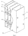
- Figure 1 is a three-dimensional view with a local sectional side of one embodiment of the present invention
- figure 2 is a structural view of an amplified micro-discharge preventive conductor rail in the figure 1 of the present invention.
- the present invention provides a metal belt-plate structured reactor, comprising positive electrodes 101, negative electrodes 102 and a metal housing 108, wherein the positive electrode 101 is positioned at the middle of the two negative electrodes 102, the positive electrodes 101 and negative electrodes 102 are arranged along the airflow direction, and the two sides of the negative electrodes 102 are fixed on the housing 108.
- n groups n is a positive integer less than 50
- positive electrodes 101 each of which is a component formed by several anti-oxidizing metal belts arrayed in parallel at an equal interval on the same plane
- n+1 negative electrodes 102 each of which is made of aluminum or stainless steel plates.
- micro-discharge preventive conductor rails 103 made of aluminum bars or stainless steel bars are installed in the plasma reactor, the two ends of the positive electrode 101 are respectively fixed on the corresponding positions on the micro-discharge preventive conductor rails respectively, and the micro-discharge preventive conductor rails 103 are electrically connected by anti-oxidation leads.
- the negative electrode 102 may also be replaced by iron, copper or other metal plates coated with nickel and chromium on the surface, but those substitutions are inferior to the electrodes made of aluminum plates or stainless steel plates in cost performance.
- the corona discharge of the positive electrode 101 made of several nickel-chromium alloy belts is uniformly distributed around the positive electrode 101 along the longitudinal direction.
- the discharge distance between the positive and negative electrodes are the same in spite of such conditions as power supply configuration; the plasma which is generated by the reactor with the positive electrode 101 made of nickel-chromium alloy belts is over twice as dense as the plasma generated by the reactor with the saw-tooth or needle tip-structured positive electrode, and the ozone amount measured is 1/4 of that generated by the reactor with the saw-tooth or needle tip-structured positive electrode, meeting the provisions of the national Indoor Air Quality Standard that ozone amounts shall be less than or equal to 0.16mg/m 3 .
- a large-sized reactor for clean rooms has 30-50 groups of positive electrodes 101
- a medium-sized reactor for offices has 20-40 groups of positive electrodes 101
- a small-sized reactor for households has 2-20 groups of positive electrodes 101. If applied to the super-large places such as subway stations and tunnels, several large-sized reactors can be combined together.
- the housing 108 may be iron plates coated with zinc, nickel, etc. with an oxidized layer or rolled from the aluminum or stainless steel plates. It must be specified that the two sides of the housing 108 in parallel to the negative electrode 102 also function as the negative electrode, which makes the structureaki, simple and solid, the properties stable, and saves materials.
- the micro-discharge preventive conductor rails 103 are provided with protruded portions 109 arrayed at an equal interval, the two ends of the positive electrode 101 are respectively fixed on the tops of the protruded portions 109 of the corresponding conduct rails; the vertically symmetrical protruded portions 109 of the micro-discharge preventive conductor rails 103 are incorporated into one group, each micro-discharge preventive conductor rail 103 has n groups of protruded portions 109, and the top of each protruded portion 109 is provided with an outward elbow.
- the two ends of the positive electrode 101 are respectively provided with a stainless steel connecting frame 110, of which the middle is punched into a square hole, and the elbow on the top of the protruded portion 109 is sleeved into the stainless steel connecting frame 110; the upper and lower ends, close to the edge of the reactor housing 108, of the negative electrode 102 are respectively provided with a projected negative electrode fixing pin 111 which is jointed and fastened with the corresponding groove on the reactor housing 108.
- the two ends of the micro-discharge conductor rail 103 are respectively provided with an insulation connection 105 fixed in the corresponding mounting hole on the reactor housing 108, and airflow channels are respectively formed on the upper and lower ends of the housing 108 along the airflow direction.
- the protruded portions 109 are stainless steel elastic plates with a thickness of 0.3-1mm.
- the stainless steel connecting frames 110 and the two ends of the positive electrode 101 are processed according to the designed length, and the stainless steel connecting frames 110 at the two ends are sleeved into the elbows at the protruded portions 109 of the corresponding micro-discharge preventive conductor rails.
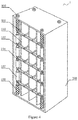
- FIG. 4 is a three-dimensional view of another embodiment of the present invention.
- the micro-discharge preventive conductor rail 103 is provided with n groups of recessed portions which are arrayed at an equal interval, the two ends of the positive electrode 101 made of metal belts are respectively fixed into the recessed portions of the corresponding micro-discharge preventive conductor rail 103; the two ends of the micro-discharge preventive conductor rail 103 are orthogonally fixed to and electrically connected with the four positive electrode metal supports 104 on the four sides of the reactor; the outer edge of the positive electrode metal support 104 is provided with several fixing rings 107 for separating adjacent micro-discharge preventive conductor rail 103 at an interval; the upper and lower ends of each positive electrode metal support 104 are respectively provided with an insulation connection 105 fastened in the corresponding mounting hole on the reactor housing 108, and an insulation connection fixing bolt (106) fastens the insulation connection 105 on the metal reactor housing 108; the upper and lower edges, close to the reactor housing 108, of the negative electrode
- the negative electrode is made of the aluminum plate is 1-2.0mm thick and has an oxidized surface, a long service life and a good-looking appearance, or the negative electrode 102 is made of the stainless steel and is 0.5-1.5mm thick. If welding technology is used in implementation, edge titling will occur, if the bent edge of the negative electrode 102 is fastened with a screw, assembly error will be generated, and both mentioned processes are inferior to this embodiment.
- the negative electrode 102 in the present invention is made from aluminum plates with oxidized surfaces, and the two sides of the negative electrode 102 are coated with nano-scaled TiO 2 . It should be particularly highlighted that the negative electrode of the plasma reactor is made from aluminum plates with oxidized surfaces, and the upper surface is coated with TiO 2 .
- the Al 2 O 3 layer generated by the oxidation treatment is only 3-4 ⁇ m thick and has no influence on the corona discharge in the 18KV P-P narrow-pulse high-voltage electric field.
- the blue light emitted from the reaction area contains ultraviolet light with a wavelength of 300-400 nm, and the peak value of the light intensity is 357nm.
- the forbidden bandwidth of TiO 2 is 3.2eV, and the wavelength threshold value of the corresponding ultraviolet ray is 387.5 nm.
- the optimal wavelength of the catalytic light source is less than or equal to 387.5 nm, and the peak value, namely 357nm, of the wavelength of the ultraviolet ray emitted from the reaction area meets this condition.
- the ultraviolet light source can be omitted, and then defects of ultraviolet lamp damage, human bodily injury and large power consumption of the ultraviolet light source are overcome.
- the distance between the elbows on two vertically symmetrical projected portions 109 in each group is designed according to the unipolar shielding effect, and the distance between two adjacent positive electrodes 101 made of the metal belts ranges from 16-26 mm.
- the distance between two adjacent micro-discharge preventive conductor rails (103) with grooves is designed according to the unipolar shielding effect, the distance between two adjacent positive electrodes (101) made of the metal belts ranges from 16-26 mm, and the fixing ring (107) can be uniform in length.
- the discharge distance between the positive electrode 101 and the negative electrode 102 is designed to be 8-18mm according to the electric field strength of the external high-voltage power supply.
- the positive electrode 101 in the present invention is made of anti-oxidation high-resistance electrothermal nickel-chromium alloy belts or iron-chromium-aluminum alloy materials.
- the metal belts forming the positive electrode 101 are 1-2mm wide and 0.05-0.2mm thick, and the thin side faces of the metal belts are aligned with and face the plane of the negative electrode 102. If the thickness is thinner, the discharge inception voltage will be lower, the concentration of the generated plasma will be higher, and the mechanical strength will be poor.
- a metal belt with a thickness of 0.08-0.12mm is optimal in the design.
- the positive electrode made of metal belts is consumed due to discharge, the area of the discharge side face is kept unchanged, and the effective service life reaches 8-12 years.
- This embodiment has another technical scheme, in which the positive electrode 101 made of the iron-chromium-aluminum metal belts has a shape and dimensions identical with those of the above schemes but has a low cost, magnetism and inferior properties.
- Figure 3 is a schematic view of the corona discharge of the positive electrode made of the metal belts.
- the reactor is externally connected with a direct current high-voltage power supply 2 and a fan, the positive electrode of the output end of the direct current high-voltage power supply is electrically connected with the positive electrode 101 of the plasma reactor 1, and the negative electrode of the output end of the direct-current high-voltage power supply is electrically connected with the negative electrode 102 of the plasma reactor 1.
- the left end of the reactor is the air inlet 5, the right end is the air outlet 6, and the positive electrode 101 and negative electrode 102 are arranged in parallel in the airflow direction.
- the corona discharge, on the negative electrode 102, of the positive electrode 101 made of the metal belts is more uniform than that of the saw-tooth or needle tip-structured positive electrode.
- the present invention can sterilize and purify the indoor air dynamically in 24 hours and has no influences on the human body or appliances and instruments.
- the sterilizing factors of the present invention are low-temperature plasma and radicals generated by exciting TiO 2 .
- the plasma is a gas cloud which consists of a great amount of positive and negative charged particles and neutral particles with combined functions of the whole electric fields and charged with quasi-neutrality.
- the plasma can severely break down and damage the cell membranes of bacteria and break the molecular bonds of gases to generate radicals such as monatomic molecules, negative oxide ions, OH ions, free oxygen atoms and H 2 O 2 , which have strong activation and oxidation capabilities. It has a good effect in killing bacteria and viruses. It can also decompose macromolecular toxic organics such as the formaldehyde, benzene, radon, ammonia, carbon monoxide, smoke and TVOC and convert them into the nontoxic and scent-free inorganic substances, such as carbon and water.
- the internal plasma reactor has an electrostatic field which can absorb particles with a minimum particle size of 0.1 ⁇ m to further purify the air. Negative oxygen ions are called “vitamins" for the air, mostly appearing near natural waterfalls and in forests.
- Vitamins Negative oxygen ions
- the energy of the light source excites the gas molecules around the TiO 2 to generate radicals with strong activity.
- Those radicals with extremely strong activity can decompose most of the organic substances and part of the inorganic substances, thereby doubling the sterilization, deodorization and air purification effects.
- micro-discharge preventive conductor rails can be replaced by simple variations of metal tubes, but the manufacturing process is very complicated and has high cost; copper or iron plates coated with nickel or chromium may be substitutes of the negative electrodes, however they will also be inevitably oxidized lasting the end.
Landscapes
- Engineering & Computer Science (AREA)
- Physics & Mathematics (AREA)
- Plasma & Fusion (AREA)
- Spectroscopy & Molecular Physics (AREA)
- Chemical & Material Sciences (AREA)
- Analytical Chemistry (AREA)
- General Chemical & Material Sciences (AREA)
- Oil, Petroleum & Natural Gas (AREA)
- Chemical Kinetics & Catalysis (AREA)
- Physical Or Chemical Processes And Apparatus (AREA)
- Disinfection, Sterilisation Or Deodorisation Of Air (AREA)
Claims (7)
- Réacteur à structure de courroies-plaques métalliques, le réacteur comprenant des électrodes positives (101) comportant deux extrémités et des électrodes négatives (102) comportant deux côtés, chaque électrode positive (101) étant située au milieu entre deux électrodes négatives (102) ; caractérisé en ce que : il y a un total de n groupes d'électrodes positives (101), n étant un nombre entier positif inférieur à 50, chaque électrode positive étant un élément formé à partir de plusieurs courroies en alliage nickel-chrome ou en alliage fer-chrome aluminium résistant à l'oxydation, présentant une largeur comprise entre 1 et 2 mm et une épaisseur comprise entre 0,05 et 0,2 mm, dotées de faces latérales minces et agencées à intervalles égaux dans un plan, et permettant d'effectuer une décharge par effet corona ; il y a un total de n+1 électrodes négatives (102) formées à partir de plaques d'aluminium ou de plaques d'acier inoxydable ; le réacteur à structure de courroies-plaques métalliques est muni également de plusieurs rails conducteurs préventifs de micro-décharge (103), formés à partir de barres d'aluminium ou de barres inoxydables ; les deux extrémités de l'électrode positive (101) sont fixées respectivement sur les positions correspondantes des rails conducteurs (103) ; les plusieurs rails conducteurs (103) sont connectés électriquement par des fils anti-oxydation ; les faces latérales minces des courroies métalliques sont orientées vers le plan de l'électrode négative (102) et alignées avec ledit plan, les faces latérales minces des courroies métalliques orientées vers le plan de l'électrode négative (102) étant des faces latérales de décharge effectuant une décharge par effet corona ; le réacteur à structure de courroies-plaques métalliques comprend en outre une enveloppe métallique (108) fournissant une entrée d'air et une sortie d'air; les électrodes négatives (102) sont situées dans la direction d'écoulement d'air entre l'entrée d'air et la sortie d'air ; les deux côtés de chaque électrode négative (102) sont fixés sur l'enveloppe (108).
- Le réacteur à structure de courroies-plaques métalliques selon la revendication 1, dans lequel le rail conducteur (103) est muni de n groupes de saillies (109) à intervalles égaux, chaque groupe consistant en une saillie verticalement supérieure et une saillie verticalement inférieure qui sont symétriques verticalement ; les deux extrémités des électrodes positives (101) sont fixées respectivement sur les parties supérieures des saillies du rail conducteur correspondant ; la partie supérieure de la saillie (109) est munie d'un coude vers l'extérieur à partir de la partie supérieure de la saillie (109) ; les deux extrémités de l'électrode positive (101) sont munies d'un cadre de liaison en acier inoxydable (110) dont le centre est perforé pour former un trou carré, et le coude au niveau de la partie supérieure de la saillie (109) est emmanché dans le trou carré du cadre de liaison en acier inoxydable (110) ; les extrémités verticalement supérieure et inférieure de l'électrode négative (102) à proximité de l'enveloppe (108) du réacteur sont munies respectivement d'un boulon (111) de fixation d'électrode négative en saillie, et une position correspondant à l'enveloppe est pourvue d'une rainure permettant l'assemblage et la fixation ; les deux extrémités du rail conducteur (103) sont munies respectivement d'un raccord isolant (105) fixé dans le trou de montage correspondant de l'enveloppe (108) ; et les extrémités verticalement supérieure et inférieure de l'enveloppe (108) sont munies de canaux d'écoulement d'air le long de la direction d'écoulement d'air entre l'entrée d'air et la sortie d'air.
- Le réacteur à structure de courroies-plaques métalliques selon la revendication 1, dans lequel le rail conducteur (103) est muni de n évidements à intervalles égaux, les deux extrémités de l'électrode positive (101) étant fixées respectivement sur les évidements correspondants du rail conducteur (103) ; les deux extrémités du rail conducteur (103) sont fixées à, et en connexion électrique avec, quatre supports métalliques (104) d'électrode positive situés orthogonalement sur quatre côtés du réacteur ; le bord externe du support métallique (104) d'électrode positive est muni de plusieurs anneaux de fixation cylindriques (107) pour le rail conducteur (103), l'anneau de fixation (107) séparant des rails conducteurs (103) adjacents à intervalles égaux; les extrémités verticalement supérieure et inférieure de chaque support métallique (104) d'électrode positive sont munies respectivement d'un raccord isolant (105) fixé au trou de montage correspondant de l'enveloppe (108) du réacteur et d'un boulon (106) de fixation de raccord isolant permettant de fixer le raccord isolant (105) sur l'enveloppe métallique (108); les côtés verticalement supérieur et inférieur, à proximité de l'enveloppe (108), de l'électrode négative (102) sont assemblés et fixés à des positions correspondantes de l'enveloppe (108) ; et l'enveloppe (108) est munie de canaux d'écoulement d'air le long de la direction d'écoulement d'air entre l'entrée d'air et la sortie d'air.
- Le réacteur à structure de courroies-plaques métalliques selon la revendication 1, dans lequel l'électrode négative (102) est formée à partir d'une plaque d'aluminium dotée d'une surface oxydée, et les deux côtés de l'électrode négative (102) sont revêtus de TiO2 nanométrique.
- Le réacteur à structure de courroies-plaques métalliques selon les revendications 1 ou 2, dans lequel la distance entre les saillies symétriques verticalement supérieure et inférieure (109) dans chaque groupe est conçue de telle façon que la distance entre les courroies métalliques de deux électrodes positives (101) adjacentes varie entre 16 et 26 mm.
- Le réacteur à structure de courroies-plaques métalliques selon la revendication 3, dans lequel la distance entre deux rails conducteurs (103) adjacents dotés d'évidements est conçue de telle façon que la distance entre les courroies métalliques de deux électrodes positives (101) adjacentes varie entre 16 et 26 mm.
- Le réacteur à structure de courroies-plaques métalliques selon les revendications 1, 2 ou 3, dans lequel la distance de décharge entre l'électrode positive (101) et l'électrode négative (102) est conçue pour être comprise entre 8 et 18 mm.
Applications Claiming Priority (2)
| Application Number | Priority Date | Filing Date | Title |
|---|---|---|---|
| CN200910263798A CN101920224B (zh) | 2009-12-31 | 2009-12-31 | 金属带--板结构反应器 |
| PCT/CN2010/002083 WO2011079510A1 (fr) | 2009-12-31 | 2010-12-17 | Réacteur à structure de courroies-plaques métalliques |
Related Child Applications (1)
| Application Number | Title | Priority Date | Filing Date |
|---|---|---|---|
| EP20152500.3 Division-Into | 2020-01-17 |
Publications (3)
| Publication Number | Publication Date |
|---|---|
| EP2520315A1 EP2520315A1 (fr) | 2012-11-07 |
| EP2520315A4 EP2520315A4 (fr) | 2014-05-21 |
| EP2520315B1 true EP2520315B1 (fr) | 2020-09-30 |
Family
ID=43335588
Family Applications (1)
| Application Number | Title | Priority Date | Filing Date |
|---|---|---|---|
| EP10840300.7A Active EP2520315B1 (fr) | 2009-12-31 | 2010-12-17 | Réacteur à structure de courroies-plaques métalliques |
Country Status (3)
| Country | Link |
|---|---|
| EP (1) | EP2520315B1 (fr) |
| CN (1) | CN101920224B (fr) |
| WO (1) | WO2011079510A1 (fr) |
Families Citing this family (9)
| Publication number | Priority date | Publication date | Assignee | Title |
|---|---|---|---|---|
| CN105478238B (zh) * | 2014-09-16 | 2017-05-03 | 孙红梅 | 丝网电极放电装置 |
| JP6333697B2 (ja) * | 2014-10-08 | 2018-05-30 | 三菱日立パワーシステムズ環境ソリューション株式会社 | 電気集じん装置 |
| DE102016202293B3 (de) | 2016-02-15 | 2017-04-27 | Wilhelm Bruckbauer | Vorrichtung zur Anordnung einer oder mehrerer Elektroden eines Plasmafilters in einem Gehäuse |
| CN105817327B (zh) * | 2016-03-24 | 2017-07-07 | 重庆净怡环保科技(集团)有限公司 | 一种幕布式电场的产生方法 |
| CN106955585A (zh) * | 2017-03-02 | 2017-07-18 | 海湾环境科技(北京)股份有限公司 | 气体处理方法及系统 |
| CN106686873B (zh) * | 2017-03-04 | 2024-02-23 | 绍兴上虞阿特兰迪电器有限公司 | 一种可拆卸的非热等离子反应器 |
| TWI754983B (zh) * | 2019-04-25 | 2022-02-11 | 大陸商上海必修福企業管理有限公司 | 用於半導體製造的潔淨室系統及其電場除塵方法 |
| CN114076378B (zh) * | 2020-08-21 | 2023-04-25 | 广东美的制冷设备有限公司 | 离子发生装置、空气处理模块及电器设备 |
| CN112426554A (zh) * | 2020-10-30 | 2021-03-02 | 重庆城市管理职业学院 | 空气消毒装置及空气消毒方法 |
Family Cites Families (11)
| Publication number | Priority date | Publication date | Assignee | Title |
|---|---|---|---|---|
| JPS4011117Y1 (fr) * | 1964-09-16 | 1965-04-17 | ||
| AR205152A1 (es) * | 1973-02-02 | 1976-04-12 | United States Filter Corp | Precipitador electrostatico humedo |
| JPS527075A (en) * | 1975-07-05 | 1977-01-19 | Hara Keiichi | Electric dust collector |
| US4381927A (en) * | 1981-04-23 | 1983-05-03 | United Mcgill Corporation | Corona electrode apparatus |
| US4472174A (en) * | 1983-04-25 | 1984-09-18 | Raymond L. Chuan | Method and apparatus for providing and using RF generated plasma for particle charging in electrostatic precipitation |
| CN2424827Y (zh) * | 2000-05-26 | 2001-03-28 | 莱州市活性碳纤维厂 | 低温等离子空气净化器 |
| JP4553555B2 (ja) * | 2003-03-11 | 2010-09-29 | 西松建設株式会社 | 排ガスの処理方法および排ガス処理装置 |
| WO2006088174A1 (fr) * | 2005-02-21 | 2006-08-24 | Matsushita Electric Industrial Co., Ltd. | Unité de récupération de poussière électrique |
| CN101920034B (zh) * | 2009-12-31 | 2013-04-17 | 周云正 | 非热等离子体反应器 |
| CN201644086U (zh) * | 2009-12-31 | 2010-11-24 | 周云正 | 金属带——板结构反应器 |
| CN101922750B (zh) * | 2009-12-31 | 2012-07-04 | 周云正 | 设有等离子体净化的抽油烟机 |
-
2009
- 2009-12-31 CN CN200910263798A patent/CN101920224B/zh active Active
-
2010
- 2010-12-17 WO PCT/CN2010/002083 patent/WO2011079510A1/fr active Application Filing
- 2010-12-17 EP EP10840300.7A patent/EP2520315B1/fr active Active
Non-Patent Citations (1)
| Title |
|---|
| None * |
Also Published As
| Publication number | Publication date |
|---|---|
| WO2011079510A1 (fr) | 2011-07-07 |
| CN101920224B (zh) | 2012-10-10 |
| EP2520315A1 (fr) | 2012-11-07 |
| EP2520315A4 (fr) | 2014-05-21 |
| CN101920224A (zh) | 2010-12-22 |
Similar Documents
| Publication | Publication Date | Title |
|---|---|---|
| EP2520315B1 (fr) | Réacteur à structure de courroies-plaques métalliques | |
| US8529830B2 (en) | Plasma sterilizing-purifying device and method for air sterilizing and purifying | |
| CN101922766B (zh) | 空气消毒净化中央空调机 | |
| CN101920026B (zh) | 隧道空气消毒净化器 | |
| CN201643058U (zh) | 等离子体与二氧化钛优化组合的空气消毒净化器 | |
| CN101920036B (zh) | 设有金属带--板结构反应器的净化器 | |
| CN201724320U (zh) | 空气消毒净化中央空调机 | |
| CN201586246U (zh) | 非热等离子体净化单元 | |
| CN101920039B (zh) | 等离子体与二氧化钛优化组合的空气消毒净化器 | |
| CN201715597U (zh) | 设有等离子体净化的抽油烟机 | |
| CN101943441B (zh) | 等离子体空气消毒净化空调机 | |
| CN201586248U (zh) | 隧道空气消毒净化器 | |
| CN101920040B (zh) | 风道式电子空气净化机 | |
| CN101920032A (zh) | 非热等离子体净化单元 | |
| CN101929255B (zh) | 设有等离子体空气消毒净化器的医院手术室 | |
| CN201586249U (zh) | 一种等离子体空气消毒净化器 | |
| CN101920038B (zh) | 潜艇低温等离子体空气消毒净化器 | |
| CN210545701U (zh) | 一种高效离子风空气净化器 | |
| CN101920034B (zh) | 非热等离子体反应器 | |
| CN101922750B (zh) | 设有等离子体净化的抽油烟机 | |
| CN201662163U (zh) | 等离子体空气消毒净化空调机 | |
| CN201644086U (zh) | 金属带——板结构反应器 | |
| CN201874265U (zh) | 设有等离子体空气消毒净化器的医院手术室 | |
| CN101920037A (zh) | 飞机座舱等离子体空气净化器 | |
| CN201586245U (zh) | 飞机座舱等离子体空气净化器 |
Legal Events
| Date | Code | Title | Description |
|---|---|---|---|
| PUAI | Public reference made under article 153(3) epc to a published international application that has entered the european phase |
Free format text: ORIGINAL CODE: 0009012 |
|
| 17P | Request for examination filed |
Effective date: 20120731 |
|
| AK | Designated contracting states |
Kind code of ref document: A1 Designated state(s): AL AT BE BG CH CY CZ DE DK EE ES FI FR GB GR HR HU IE IS IT LI LT LU LV MC MK MT NL NO PL PT RO RS SE SI SK SM TR |
|
| DAX | Request for extension of the european patent (deleted) | ||
| A4 | Supplementary search report drawn up and despatched |
Effective date: 20140423 |
|
| RIC1 | Information provided on ipc code assigned before grant |
Ipc: B03C 3/40 20060101ALI20140414BHEP Ipc: A61L 9/22 20060101AFI20140414BHEP Ipc: B03C 3/38 20060101ALI20140414BHEP |
|
| 17Q | First examination report despatched |
Effective date: 20151109 |
|
| APBK | Appeal reference recorded |
Free format text: ORIGINAL CODE: EPIDOSNREFNE |
|
| APBN | Date of receipt of notice of appeal recorded |
Free format text: ORIGINAL CODE: EPIDOSNNOA2E |
|
| APBR | Date of receipt of statement of grounds of appeal recorded |
Free format text: ORIGINAL CODE: EPIDOSNNOA3E |
|
| APAF | Appeal reference modified |
Free format text: ORIGINAL CODE: EPIDOSCREFNE |
|
| APAF | Appeal reference modified |
Free format text: ORIGINAL CODE: EPIDOSCREFNE |
|
| APBT | Appeal procedure closed |
Free format text: ORIGINAL CODE: EPIDOSNNOA9E |
|
| RAP1 | Party data changed (applicant data changed or rights of an application transferred) |
Owner name: ZHEJIANG TIANQING ENVIRONMENTAL PROTECTION TECHNOLOGY CO., LTD. |
|
| RAP1 | Party data changed (applicant data changed or rights of an application transferred) |
Owner name: ZHEJIANG TIANQING ENVIRONMENTAL PROTECTION TECHNOLOGY CO., LTD. |
|
| GRAP | Despatch of communication of intention to grant a patent |
Free format text: ORIGINAL CODE: EPIDOSNIGR1 |
|
| STAA | Information on the status of an ep patent application or granted ep patent |
Free format text: STATUS: GRANT OF PATENT IS INTENDED |
|
| RIC1 | Information provided on ipc code assigned before grant |
Ipc: B03C 3/41 20060101ALI20200528BHEP Ipc: B01D 53/32 20060101ALI20200528BHEP Ipc: B03C 3/40 20060101ALI20200528BHEP Ipc: B03C 3/38 20060101ALI20200528BHEP Ipc: B03C 3/08 20060101ALI20200528BHEP Ipc: H05H 1/24 20060101ALI20200528BHEP Ipc: A61L 9/20 20060101ALI20200528BHEP Ipc: A61L 9/22 20060101AFI20200528BHEP Ipc: B03C 3/60 20060101ALI20200528BHEP Ipc: B03C 3/47 20060101ALI20200528BHEP |
|
| INTG | Intention to grant announced |
Effective date: 20200618 |
|
| GRAS | Grant fee paid |
Free format text: ORIGINAL CODE: EPIDOSNIGR3 |
|
| GRAA | (expected) grant |
Free format text: ORIGINAL CODE: 0009210 |
|
| STAA | Information on the status of an ep patent application or granted ep patent |
Free format text: STATUS: THE PATENT HAS BEEN GRANTED |
|
| AK | Designated contracting states |
Kind code of ref document: B1 Designated state(s): AL AT BE BG CH CY CZ DE DK EE ES FI FR GB GR HR HU IE IS IT LI LT LU LV MC MK MT NL NO PL PT RO RS SE SI SK SM TR |
|
| REG | Reference to a national code |
Ref country code: GB Ref legal event code: FG4D Ref country code: CH Ref legal event code: EP |
|
| REG | Reference to a national code |
Ref country code: AT Ref legal event code: REF Ref document number: 1318119 Country of ref document: AT Kind code of ref document: T Effective date: 20201015 |
|
| REG | Reference to a national code |
Ref country code: DE Ref legal event code: R096 Ref document number: 602010065582 Country of ref document: DE |
|
| REG | Reference to a national code |
Ref country code: FI Ref legal event code: FGE |
|
| REG | Reference to a national code |
Ref country code: IE Ref legal event code: FG4D |
|
| REG | Reference to a national code |
Ref country code: NL Ref legal event code: FP |
|
| PG25 | Lapsed in a contracting state [announced via postgrant information from national office to epo] |
Ref country code: HR Free format text: LAPSE BECAUSE OF FAILURE TO SUBMIT A TRANSLATION OF THE DESCRIPTION OR TO PAY THE FEE WITHIN THE PRESCRIBED TIME-LIMIT Effective date: 20200930 Ref country code: NO Free format text: LAPSE BECAUSE OF FAILURE TO SUBMIT A TRANSLATION OF THE DESCRIPTION OR TO PAY THE FEE WITHIN THE PRESCRIBED TIME-LIMIT Effective date: 20201230 Ref country code: SE Free format text: LAPSE BECAUSE OF FAILURE TO SUBMIT A TRANSLATION OF THE DESCRIPTION OR TO PAY THE FEE WITHIN THE PRESCRIBED TIME-LIMIT Effective date: 20200930 Ref country code: BG Free format text: LAPSE BECAUSE OF FAILURE TO SUBMIT A TRANSLATION OF THE DESCRIPTION OR TO PAY THE FEE WITHIN THE PRESCRIBED TIME-LIMIT Effective date: 20201230 Ref country code: GR Free format text: LAPSE BECAUSE OF FAILURE TO SUBMIT A TRANSLATION OF THE DESCRIPTION OR TO PAY THE FEE WITHIN THE PRESCRIBED TIME-LIMIT Effective date: 20201231 |
|
| REG | Reference to a national code |
Ref country code: AT Ref legal event code: MK05 Ref document number: 1318119 Country of ref document: AT Kind code of ref document: T Effective date: 20200930 |
|
| PG25 | Lapsed in a contracting state [announced via postgrant information from national office to epo] |
Ref country code: RS Free format text: LAPSE BECAUSE OF FAILURE TO SUBMIT A TRANSLATION OF THE DESCRIPTION OR TO PAY THE FEE WITHIN THE PRESCRIBED TIME-LIMIT Effective date: 20200930 Ref country code: LV Free format text: LAPSE BECAUSE OF FAILURE TO SUBMIT A TRANSLATION OF THE DESCRIPTION OR TO PAY THE FEE WITHIN THE PRESCRIBED TIME-LIMIT Effective date: 20200930 |
|
| REG | Reference to a national code |
Ref country code: LT Ref legal event code: MG4D |
|
| PG25 | Lapsed in a contracting state [announced via postgrant information from national office to epo] |
Ref country code: SM Free format text: LAPSE BECAUSE OF FAILURE TO SUBMIT A TRANSLATION OF THE DESCRIPTION OR TO PAY THE FEE WITHIN THE PRESCRIBED TIME-LIMIT Effective date: 20200930 Ref country code: RO Free format text: LAPSE BECAUSE OF FAILURE TO SUBMIT A TRANSLATION OF THE DESCRIPTION OR TO PAY THE FEE WITHIN THE PRESCRIBED TIME-LIMIT Effective date: 20200930 Ref country code: LT Free format text: LAPSE BECAUSE OF FAILURE TO SUBMIT A TRANSLATION OF THE DESCRIPTION OR TO PAY THE FEE WITHIN THE PRESCRIBED TIME-LIMIT Effective date: 20200930 Ref country code: PT Free format text: LAPSE BECAUSE OF FAILURE TO SUBMIT A TRANSLATION OF THE DESCRIPTION OR TO PAY THE FEE WITHIN THE PRESCRIBED TIME-LIMIT Effective date: 20210201 Ref country code: CZ Free format text: LAPSE BECAUSE OF FAILURE TO SUBMIT A TRANSLATION OF THE DESCRIPTION OR TO PAY THE FEE WITHIN THE PRESCRIBED TIME-LIMIT Effective date: 20200930 Ref country code: EE Free format text: LAPSE BECAUSE OF FAILURE TO SUBMIT A TRANSLATION OF THE DESCRIPTION OR TO PAY THE FEE WITHIN THE PRESCRIBED TIME-LIMIT Effective date: 20200930 |
|
| PG25 | Lapsed in a contracting state [announced via postgrant information from national office to epo] |
Ref country code: PL Free format text: LAPSE BECAUSE OF FAILURE TO SUBMIT A TRANSLATION OF THE DESCRIPTION OR TO PAY THE FEE WITHIN THE PRESCRIBED TIME-LIMIT Effective date: 20200930 Ref country code: ES Free format text: LAPSE BECAUSE OF FAILURE TO SUBMIT A TRANSLATION OF THE DESCRIPTION OR TO PAY THE FEE WITHIN THE PRESCRIBED TIME-LIMIT Effective date: 20200930 Ref country code: IS Free format text: LAPSE BECAUSE OF FAILURE TO SUBMIT A TRANSLATION OF THE DESCRIPTION OR TO PAY THE FEE WITHIN THE PRESCRIBED TIME-LIMIT Effective date: 20210130 Ref country code: AT Free format text: LAPSE BECAUSE OF FAILURE TO SUBMIT A TRANSLATION OF THE DESCRIPTION OR TO PAY THE FEE WITHIN THE PRESCRIBED TIME-LIMIT Effective date: 20200930 Ref country code: AL Free format text: LAPSE BECAUSE OF FAILURE TO SUBMIT A TRANSLATION OF THE DESCRIPTION OR TO PAY THE FEE WITHIN THE PRESCRIBED TIME-LIMIT Effective date: 20200930 |
|
| PG25 | Lapsed in a contracting state [announced via postgrant information from national office to epo] |
Ref country code: SK Free format text: LAPSE BECAUSE OF FAILURE TO SUBMIT A TRANSLATION OF THE DESCRIPTION OR TO PAY THE FEE WITHIN THE PRESCRIBED TIME-LIMIT Effective date: 20200930 |
|
| REG | Reference to a national code |
Ref country code: DE Ref legal event code: R097 Ref document number: 602010065582 Country of ref document: DE |
|
| REG | Reference to a national code |
Ref country code: CH Ref legal event code: PL |
|
| PLBE | No opposition filed within time limit |
Free format text: ORIGINAL CODE: 0009261 |
|
| STAA | Information on the status of an ep patent application or granted ep patent |
Free format text: STATUS: NO OPPOSITION FILED WITHIN TIME LIMIT |
|
| PG25 | Lapsed in a contracting state [announced via postgrant information from national office to epo] |
Ref country code: MC Free format text: LAPSE BECAUSE OF FAILURE TO SUBMIT A TRANSLATION OF THE DESCRIPTION OR TO PAY THE FEE WITHIN THE PRESCRIBED TIME-LIMIT Effective date: 20200930 Ref country code: DK Free format text: LAPSE BECAUSE OF FAILURE TO SUBMIT A TRANSLATION OF THE DESCRIPTION OR TO PAY THE FEE WITHIN THE PRESCRIBED TIME-LIMIT Effective date: 20200930 |
|
| REG | Reference to a national code |
Ref country code: BE Ref legal event code: MM Effective date: 20201231 |
|
| 26N | No opposition filed |
Effective date: 20210701 |
|
| PG25 | Lapsed in a contracting state [announced via postgrant information from national office to epo] |
Ref country code: LU Free format text: LAPSE BECAUSE OF NON-PAYMENT OF DUE FEES Effective date: 20201217 Ref country code: IE Free format text: LAPSE BECAUSE OF NON-PAYMENT OF DUE FEES Effective date: 20201217 |
|
| PG25 | Lapsed in a contracting state [announced via postgrant information from national office to epo] |
Ref country code: CH Free format text: LAPSE BECAUSE OF NON-PAYMENT OF DUE FEES Effective date: 20201231 Ref country code: LI Free format text: LAPSE BECAUSE OF NON-PAYMENT OF DUE FEES Effective date: 20201231 Ref country code: SI Free format text: LAPSE BECAUSE OF FAILURE TO SUBMIT A TRANSLATION OF THE DESCRIPTION OR TO PAY THE FEE WITHIN THE PRESCRIBED TIME-LIMIT Effective date: 20200930 |
|
| PG25 | Lapsed in a contracting state [announced via postgrant information from national office to epo] |
Ref country code: IS Free format text: LAPSE BECAUSE OF FAILURE TO SUBMIT A TRANSLATION OF THE DESCRIPTION OR TO PAY THE FEE WITHIN THE PRESCRIBED TIME-LIMIT Effective date: 20210130 Ref country code: TR Free format text: LAPSE BECAUSE OF FAILURE TO SUBMIT A TRANSLATION OF THE DESCRIPTION OR TO PAY THE FEE WITHIN THE PRESCRIBED TIME-LIMIT Effective date: 20200930 Ref country code: MT Free format text: LAPSE BECAUSE OF FAILURE TO SUBMIT A TRANSLATION OF THE DESCRIPTION OR TO PAY THE FEE WITHIN THE PRESCRIBED TIME-LIMIT Effective date: 20200930 Ref country code: CY Free format text: LAPSE BECAUSE OF FAILURE TO SUBMIT A TRANSLATION OF THE DESCRIPTION OR TO PAY THE FEE WITHIN THE PRESCRIBED TIME-LIMIT Effective date: 20200930 |
|
| PG25 | Lapsed in a contracting state [announced via postgrant information from national office to epo] |
Ref country code: MK Free format text: LAPSE BECAUSE OF FAILURE TO SUBMIT A TRANSLATION OF THE DESCRIPTION OR TO PAY THE FEE WITHIN THE PRESCRIBED TIME-LIMIT Effective date: 20200930 |
|
| PG25 | Lapsed in a contracting state [announced via postgrant information from national office to epo] |
Ref country code: BE Free format text: LAPSE BECAUSE OF NON-PAYMENT OF DUE FEES Effective date: 20201231 |
|
| PGFP | Annual fee paid to national office [announced via postgrant information from national office to epo] |
Ref country code: NL Payment date: 20231123 Year of fee payment: 14 |
|
| PGFP | Annual fee paid to national office [announced via postgrant information from national office to epo] |
Ref country code: GB Payment date: 20231116 Year of fee payment: 14 |
|
| PGFP | Annual fee paid to national office [announced via postgrant information from national office to epo] |
Ref country code: IT Payment date: 20231128 Year of fee payment: 14 Ref country code: FR Payment date: 20231122 Year of fee payment: 14 Ref country code: FI Payment date: 20231218 Year of fee payment: 14 Ref country code: DE Payment date: 20231121 Year of fee payment: 14 |