EP2520242A1 - Surgical forceps - Google Patents
Surgical forceps Download PDFInfo
- Publication number
- EP2520242A1 EP2520242A1 EP12166780A EP12166780A EP2520242A1 EP 2520242 A1 EP2520242 A1 EP 2520242A1 EP 12166780 A EP12166780 A EP 12166780A EP 12166780 A EP12166780 A EP 12166780A EP 2520242 A1 EP2520242 A1 EP 2520242A1
- Authority
- EP
- European Patent Office
- Prior art keywords
- jaw members
- knife bar
- knife
- tissue
- slot
- Prior art date
- Legal status (The legal status is an assumption and is not a legal conclusion. Google has not performed a legal analysis and makes no representation as to the accuracy of the status listed.)
- Granted
Links
Images






Classifications
-
- A—HUMAN NECESSITIES
- A61—MEDICAL OR VETERINARY SCIENCE; HYGIENE
- A61B—DIAGNOSIS; SURGERY; IDENTIFICATION
- A61B18/00—Surgical instruments, devices or methods for transferring non-mechanical forms of energy to or from the body
- A61B18/04—Surgical instruments, devices or methods for transferring non-mechanical forms of energy to or from the body by heating
- A61B18/12—Surgical instruments, devices or methods for transferring non-mechanical forms of energy to or from the body by heating by passing a current through the tissue to be heated, e.g. high-frequency current
- A61B18/14—Probes or electrodes therefor
- A61B18/1442—Probes having pivoting end effectors, e.g. forceps
- A61B18/1445—Probes having pivoting end effectors, e.g. forceps at the distal end of a shaft, e.g. forceps or scissors at the end of a rigid rod
-
- A—HUMAN NECESSITIES
- A61—MEDICAL OR VETERINARY SCIENCE; HYGIENE
- A61B—DIAGNOSIS; SURGERY; IDENTIFICATION
- A61B17/00—Surgical instruments, devices or methods
- A61B17/12—Surgical instruments, devices or methods for ligaturing or otherwise compressing tubular parts of the body, e.g. blood vessels or umbilical cord
-
- A—HUMAN NECESSITIES
- A61—MEDICAL OR VETERINARY SCIENCE; HYGIENE
- A61B—DIAGNOSIS; SURGERY; IDENTIFICATION
- A61B17/00—Surgical instruments, devices or methods
- A61B17/32—Surgical cutting instruments
- A61B2017/320052—Guides for cutting instruments
-
- A—HUMAN NECESSITIES
- A61—MEDICAL OR VETERINARY SCIENCE; HYGIENE
- A61B—DIAGNOSIS; SURGERY; IDENTIFICATION
- A61B18/00—Surgical instruments, devices or methods for transferring non-mechanical forms of energy to or from the body
- A61B2018/00053—Mechanical features of the instrument of device
- A61B2018/00297—Means for providing haptic feedback
-
- A—HUMAN NECESSITIES
- A61—MEDICAL OR VETERINARY SCIENCE; HYGIENE
- A61B—DIAGNOSIS; SURGERY; IDENTIFICATION
- A61B18/00—Surgical instruments, devices or methods for transferring non-mechanical forms of energy to or from the body
- A61B2018/00636—Sensing and controlling the application of energy
- A61B2018/00642—Sensing and controlling the application of energy with feedback, i.e. closed loop control
-
- A—HUMAN NECESSITIES
- A61—MEDICAL OR VETERINARY SCIENCE; HYGIENE
- A61B—DIAGNOSIS; SURGERY; IDENTIFICATION
- A61B18/00—Surgical instruments, devices or methods for transferring non-mechanical forms of energy to or from the body
- A61B18/04—Surgical instruments, devices or methods for transferring non-mechanical forms of energy to or from the body by heating
- A61B18/12—Surgical instruments, devices or methods for transferring non-mechanical forms of energy to or from the body by heating by passing a current through the tissue to be heated, e.g. high-frequency current
- A61B18/14—Probes or electrodes therefor
- A61B18/1442—Probes having pivoting end effectors, e.g. forceps
- A61B2018/1452—Probes having pivoting end effectors, e.g. forceps including means for cutting
- A61B2018/1455—Probes having pivoting end effectors, e.g. forceps including means for cutting having a moving blade for cutting tissue grasped by the jaws
-
- A—HUMAN NECESSITIES
- A61—MEDICAL OR VETERINARY SCIENCE; HYGIENE
- A61B—DIAGNOSIS; SURGERY; IDENTIFICATION
- A61B90/00—Instruments, implements or accessories specially adapted for surgery or diagnosis and not covered by any of the groups A61B1/00 - A61B50/00, e.g. for luxation treatment or for protecting wound edges
- A61B90/08—Accessories or related features not otherwise provided for
- A61B2090/0807—Indication means
- A61B2090/0811—Indication means for the position of a particular part of an instrument with respect to the rest of the instrument, e.g. position of the anvil of a stapling instrument
Definitions
- the present disclosure relates to a surgical forceps, and more particularly, to an electrosurgical forceps capable of sealing and cutting tissue.
- a forceps in accordance with the present disclosure, includes an end effector assembly having first and second jaw members disposed in opposed relation relative to one another. One (or both) of the jaw members is moveable with respect to the other from a spaced-apart position to an approximated position for grasping tissue therebetween.
- a knife is longitudinally translatable with respect to the first and second jaw members between a retracted position, an intermediate position, and an extended position.
- the grasped tissue In the retracted and intermediate positions, the grasped tissue is not exposed to a knife blade of the knife so that the grasped tissue is not cut.
- the knife includes a slot defined therein and wherein one of the jaw members, e.g., the first jaw member, includes a pin engaged within the slot.
- the slot defined within the knife is configured such that, when the knife is translated from the retracted position to the intermediate position, the first and second jaw members are moved from the spaced-apart position to the approximated position to grasp tissue therebetween.
- the slot may further be configured such that, upon translation of the knife from the intermediate position to the extended position, the knife is extended between the jaw members to cut tissue grasped therebetween.
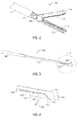
- Fig. 2 is an enlarged, perspective view of the end effector assembly of Fig. 1 ;
- Fig. 3 is a perspective view of a knife assembly for use with the end effector assembly of Fig. 1 ;
- Fig. 4 is an enlarged, perspective view of the distal end of the knife assembly of Fig. 3 ;
- Fig. 5 is a perspective view of the end effector assembly of Fig. 1 shown with parts separated;
- Fig. 12 is a side view of the forceps of Fig. 1 wherein a portion of the housing has been removed to show the internal components therein and wherein the handle is disposed in a third position;
- Pin 105 is secured within second apertures 116 of proximal flanges 113 on either side of knife bar 142 to securely couple knife bar 142 and jaw member 110 to one another.
- a drive pin 250 may be transversely engaged within knife bar 242, with flanges 213, 227 of jaw members 210, 220, respectively, defining slots 216, 226 therethrough.
- pin 105 is displaced a relatively large distance with respect to longitudinal axis "A-A" upon translation along ramped portion 148 of slot 147 such that jaw member 110 is rotated a greater degree with respect to pivot pin 103 to the approximated position to define a relatively small gap distance between sealing surfaces 112, 122 of jaw members 110, 120, respectively.
- Slot 147 of knife bar 142 defines a longitudinal portion 149 centered on longitudinal axis "A-A” and extending proximally from ramped portion 148 such that, as knife bar 142 is translated distally from the intermediate position to the extended position, pin 105 is maintained on longitudinal axis "A-A" and, thus, jaw members 110, 120 are maintained in the approximated position.
- handle assembly 30 and knife assembly 140 cooperate with end effector assembly 100 to move jaw members 110, 120 between the spaced-apart and approximated positions and to advance knife blade 144 therebetween with minimal components.
- end effector assembly 100 may be used for grasping and sealing tissue, for grasping and cutting tissue, or for grasping, sealing, and cutting tissue.
Landscapes
- Health & Medical Sciences (AREA)
- Surgery (AREA)
- Engineering & Computer Science (AREA)
- Life Sciences & Earth Sciences (AREA)
- Biomedical Technology (AREA)
- Otolaryngology (AREA)
- Nuclear Medicine, Radiotherapy & Molecular Imaging (AREA)
- Plasma & Fusion (AREA)
- Physics & Mathematics (AREA)
- Heart & Thoracic Surgery (AREA)
- Medical Informatics (AREA)
- Molecular Biology (AREA)
- Animal Behavior & Ethology (AREA)
- General Health & Medical Sciences (AREA)
- Public Health (AREA)
- Veterinary Medicine (AREA)
- Surgical Instruments (AREA)
Abstract
Description
- The present disclosure relates to a surgical forceps, and more particularly, to an electrosurgical forceps capable of sealing and cutting tissue.
- A forceps is a plier-like instrument that relies on mechanical action between its jaws to grasp, clamp and constrict vessels or tissue. Electrosurgical forceps utilize both mechanical clamping action and electrical energy to affect hemostasis by heating tissue and blood vessels to coagulate and/or cauterize tissue. Certain surgical procedures require more than simply cauterizing tissue and rely on the unique combination of clamping pressure, precise electrosurgical energy control and gap distance (i.e., distance between opposing jaw members when closed about tissue) to "seal" tissue, vessels and certain vascular bundles.
- Typically, once a vessel is sealed, the surgeon has to accurately sever the vessel along the newly formed tissue seal. Accordingly, many vessel sealing instruments have been designed that incorporate a knife or blade member that effectively severs the tissue after forming a tissue seal. Many of such instruments require the surgeon to actuate a first trigger to grasp tissue between the jaw members, e.g., to perform the sealing operation, and then to actuate a second trigger once the tissue seal has been formed, to advance the knife through tissue to sever the newly formed tissue seal.
- It would therefore be advantageous to develop an instrument that reduces the number of steps required to grasp, seal, and cut tissue. For example, commonly-assigned
U.S. Patent No. 7,628,791 to Garrison et al. , the entire contents of which are hereby incorporated by reference herein, discloses a single-action tissue sealer capable of grasping, sealing and cutting tissue in a single action. - In accordance with the present disclosure, a forceps is provided. The forceps includes an end effector assembly having first and second jaw members disposed in opposed relation relative to one another. One (or both) of the jaw members is moveable with respect to the other from a spaced-apart position to an approximated position for grasping tissue therebetween. A knife is longitudinally translatable with respect to the first and second jaw members between a retracted position, an intermediate position, and an extended position. The knife is coupled to one (or both) of the jaw members via a complementary cam, preferably pin-slot, engagement such that, upon translation of the knife from the retracted position to the intermediate position, the first and second jaw members are moved to the approximated position to grasp tissue therebetween and such that, upon translation of the knife from the intermediate position to the extended position, the knife is extended between the jaw members to cut tissue grasped therebetween.
- In the retracted and intermediate positions, the grasped tissue is not exposed to a knife blade of the knife so that the grasped tissue is not cut.
- The cam or pin-slot engagement exists between a proximal portion of the jaw member or members and a distal portion of the knife/knife bar.
- The jaw members are rotatable between the spaced-apart and approximated positions about a pivot pin or pivot axis.
- In one embodiment, each of the first and second jaw members includes an opposed electrically conductive tissue sealing surface adapted to connect to an electrosurgical energy source to communicate energy to tissue grasped between the jaw members.
- In another embodiment, one (or both) of the first and second jaw members includes a knife channel defined therein. The knife channel(s) is configured to permit reciprocation of the knife therethrough. The knife channel(s) may define a T-shaped longitudinal cross-sectional configuration or an L-shaped longitudinal cross-sectional configuration or other longitudinal cross-section in which first and second orthogonal or substantially orthogonal longitudinal knife guide channels are provided. Further, the knife may define a longitudinal cross-sectional configuration complementary to longitudinal cross-sectional configuration of the knife channel(s).
- In yet another embodiment, the knife includes a slot defined therein and wherein one of the jaw members, e.g., the first jaw member, includes a pin engaged within the slot. The slot defined within the knife is configured such that, when the knife is translated from the retracted position to the intermediate position, the first and second jaw members are moved from the spaced-apart position to the approximated position to grasp tissue therebetween. The slot may further be configured such that, upon translation of the knife from the intermediate position to the extended position, the knife is extended between the jaw members to cut tissue grasped therebetween.
- Alternatively, the knife may include a pin engaged thereon in transverse relation relative thereto and the first and second jaw members may each include a slot defined therethrough. In such an embodiment, the slots are configured such that, when the knife is translated from the retracted position to the intermediate position, the first and second jaw members are moved from the spaced-apart position to the approximated position to grasp tissue therebetween. The slots may further be configured such that, upon translation of the knife from the intermediate position to the extended position, the knife is extended at least partially between the jaw members to cut tissue grasped therebetween.
- In still another embodiment, when the first and second jaw members are disposed in the approximated position, a pre-determined gap distance is defined therebetween.
- In still yet another embodiment, a handle assembly is provided. The handle assembly is coupled to the end effector assembly and is selectively moveable between an initial position, a first actuated position, and a second actuated position for translating the knife between the retracted position, the intermediate position, and the extended position, respectively. The handle assembly may further include one or more feedback features for providing audible, tactile, and/or visual feedback as to the position of the handle assembly. For example, the movable handle may be relatively resistant to movement out of at least one, any two or all three of the initial, first actuated and second actuated position.
- Another embodiment of a forceps provided in accordance with the present disclosure includes a handle assembly including a moveable handle moveable between a first position, a second position, and a third position. The handle assembly has a shaft extending distally therefrom. An end effector assembly is disposed at a distal end of the shaft and includes first and second jaw members disposed in opposed relation relative to one another. One or both of the jaw members is moveable with respect to the other from a spaced-apart position to an approximated position for grasping tissue therebetween. One or both of the jaw members further includes a pin extending therethrough. A knife bar is disposed within the shaft and is longitudinally translatable with respect to the first and second jaw members between a retracted position, an intermediate position, and an extended position upon movement of the moveable handle between the first position, the second position, and the third position, respectively. The knife bar includes a slot defined therein that is configured to receive the pin of the jaw member(s) therethrough such that, upon translation of the knife bar from the retracted position to the intermediate position, the first and second jaw members are moved to the approximated position to grasp tissue therebetween and such that, upon translation of the knife bar from the intermediate position to the extended position, the knife bar is extended between the jaw members to cut tissue grasped therebetween.
- Yet another embodiment of a forceps provided in accordance with the present disclosure similarly includes a handle assembly having a moveable handle that is moveable between a first position, a second position, and a third position. A shaft extends distally from the handle assembly and includes an end effector assembly disposed at a distal end thereof. The end effector assembly includes first and second jaw members disposed in opposed relation relative to one another. One or both of the jaw members is moveable with respect to the other from a spaced-apart position to an approximated position for grasping tissue therebetween. One or both of the jaw members includes a proximal flange having a slot defined therethrough. A knife bar is disposed within the shaft and is longitudinally translatable with respect to the first and second jaw members between a retracted position, an intermediate position, and an extended position upon movement of the moveable handle between the first position, the second position, and the third position. The knife bar includes a pin engaged therein and extending transversely relative thereto that is configured for engagement within the slot(s) of the jaw member(s) such that, upon translation of the knife bar from the retracted position to the intermediate position, the first and second jaw members are moved to the approximated position to grasp tissue therebetween and such that, upon translation of the knife bar from the intermediate position to the extended position, the knife bar is extended between the jaw members to cut tissue grasped therebetween.
- Various embodiments of the subject instrument are described herein with reference to the drawings wherein:
-
Fig. 1 is a perspective view of a forceps having an end effector assembly in accordance with an embodiment of the present disclosure; -
Fig. 2 is an enlarged, perspective view of the end effector assembly ofFig. 1 ; -
Fig. 3 is a perspective view of a knife assembly for use with the end effector assembly ofFig. 1 ; -
Fig. 4 is an enlarged, perspective view of the distal end of the knife assembly ofFig. 3 ; -
Fig. 5 is a perspective view of the end effector assembly ofFig. 1 shown with parts separated; -
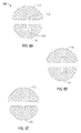
Fig. 6A is a transverse, cross-sectional view of the end effector assembly ofFig.1 ; -
Fig. 6B is a transverse, cross-sectional view of another embodiment of an end effector assembly similar to the end effector assembly ofFig. 1 ; -
Fig. 6C is a transverse, cross-sectional view of yet another embodiment of an end effector assembly similar to the end effector assembly ofFig. 1 ; -
Fig. 7 is a side, cross-sectional view of the end effector assembly ofFig. 1 with the knife assembly in a first position; -
Fig. 8 is a side, cross-sectional view of the end effector assembly ofFig. 1 with the knife assembly in a second position; -
Fig. 9 is a side, cross-sectional view of the end effector assembly ofFig. 1 with the knife assembly in a third position; -
Fig. 10 is a side view of the forceps ofFig. 1 wherein a portion of the housing has been removed to show the internal components therein and wherein the handle is disposed in a first position; -
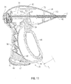
Fig. 11 is a side view of the forceps ofFig. 1 wherein a portion of the housing has been removed to show the internal components therein and wherein the handle is disposed in a second position; -
Fig. 12 is a side view of the forceps ofFig. 1 wherein a portion of the housing has been removed to show the internal components therein and wherein the handle is disposed in a third position; and -
Fig. 13 is a perspective view of another embodiment of an end effector assembly provided in accordance with the present disclosure and shown with parts separated. - Embodiments of the presently disclosed surgical instrument are described in detail with reference to the drawing figures wherein like reference numerals identify similar or identical elements, As used herein, the term "distal" refers to the portion that is being described that is further from a user, while the term "proximal" refers to the portion that is being described that is closer to a user.
- Turning now to
Fig. 1 , aforceps 10 is shown including ahousing 20, ahandle assembly 30, anactuator 70, a rotatingassembly 80, and anend effector assembly 100.Forceps 10 further includes ashaft 12 having adistal end 14 configured to mechanically engageend effector assembly 100 and aproximal end 16 that mechanically engageshousing 20.Forceps 10 also includeselectrosurgical cable 310 that connectsforceps 10 to a generator (not shown) or other suitable power source, althoughforceps 10 may alternatively be configured as a battery-powered instrument.Cable 310 has sufficient length to extend throughshaft 12 in order to provide electrical energy to at least one ofjaw members end effector assembly 100. Rotatingassembly 80 is rotatable in either direction about a longitudinal axis "A-A" to rotateend effector assembly 100 about longitudinal axis "A-A" with respect toshaft 12. - Turning now to
Fig. 2 ,end effector assembly 100 is shown attached at adistal end 14 ofshaft 12.End effector assembly 100 includes a pair of opposingjaw members End effector assembly 100 is designed as a unilateral assembly, i.e.,jaw member 120 is fixed relative to theshaft 12 andjaw member 110 is moveable, e.g., pivotable, relative tojaw member 120 between a spaced-apart position and an approximated position. However, either, or bothjaw members - With continued reference to
Fig. 2 , eachjaw member tissue sealing surface jaw members surfaces 112 122. With tissue grasped between sealingsurfaces jaw members tissue sealing surfaces Fig. 1 ) may be selectively actuatable to supply electrical energy tojaw members jaw members jaw members - As best shown in
Fig. 5 , and as mentioned above,jaw members pivot pin 103. More particularly,jaw member 110 includes a pair ofproximal flanges 113, each having afirst aperture 114 defined therethrough. Similarly,jaw member 120 includes a pair ofproximal flanges 123, each having afirst aperture 124 defined therethrough.Proximal flanges 123 ofjaw member 120 are further spaced thanproximal flanges 113 ofjaw member 110, such that, during assembly,proximal flanges 113 ofjaw member 110 are inserted betweenproximal flanges 123 ofjaw member 120 to alignfirst apertures 114 ofproximal flanges 113 ofjaw member 110 andfirst apertures 124 ofproximal flanges 123 ofjaw member 120.Pivot pin 103 is disposed through and engaged withinfirst apertures jaw members jaw members jaw members - Referring now to
Fig. 5 , in conjunction withFigs. 3-4 , aknife assembly 140 is disposed withinshaft 12. As shown inFig. 5 ,knife assembly 140 includes aknife bar 142 and aknife blade 144 disposed at a distal end ofknife bar 142.Knife bar 142 is engaged to aknife holder 146 at a proximal end thereof, as shown inFig. 3 . As will be described in detail below,knife holder 146 extends proximally throughshaft 12 into housing 20 (Fig. 1 ), ultimately coupling to moveable handle 40 (Fig. 1 ) to permit a user to selectively control the longitudinal translation ofknife holder 146 and, thus,knife bar 142. - With continued reference to
Figs. 3-5 ,knife bar 142 extends distally fromknife holder 146 and is coupled tojaw member 110 such that, whenknife bar 142 is translated distally, e.g., upon actuation of moveable handle 40 (Fig. 1 ),jaw member 110 is pivoted aboutpivot pin 103 and moved with respect tojaw member 120 from the spaced-apart position to a position to grasp tissue therebetween. Upon further distal translation ofknife bar 142, e.g., upon further actuation of moveable handle 40 (Fig. 1 ),knife blade 144 is advanced distally fromshaft 12 throughjaw members knife channel 115 is defined within one or bothjaw members knife blade 144 therethrough. - As mentioned above,
knife bar 142 is coupled tojaw member 110. More particularly,proximal flanges 113 ofjaw member 110 each include asecond aperture 116 defined therethrough and offset belowfirst apertures 114, whileknife bar 142 includes alongitudinal slot 147 defined therein. During assembly,knife bar 142 is positioned betweenproximal flanges 113 ofjaw member 110 and apin 105 is inserted throughsecond aperture 116 of oneproximal flange 113 ofjaw member 110, throughslot 147 ofknife bar 142, and throughsecond aperture 116 of the otherproximal flange 113 ofjaw member 110.Pin 105 is secured withinsecond apertures 116 ofproximal flanges 113 on either side ofknife bar 142 to securely coupleknife bar 142 andjaw member 110 to one another. Alternatively, as will be described below with reference toFig. 13 , adrive pin 250 may be transversely engaged withinknife bar 242, withflanges jaw members slots - As a result of the above-described coupling of
knife bar 142 andjaw member 110,pin 105 is translated alongslot 147 ofknife bar 142 whenknife bar 142 is translated longitudinally with respect tojaw member 110 due to the engagement ofpin 105 withinsecond apertures 116 ofproximal flanges 113 ofjaw member 110. Further, aspin 105 is translated alongslot 147, the transverse position ofpin 105 relative to longitudinal axis "A-A" is determined by the configuration ofslot 147 ofknife bar 142. For example, ifpin 105 were translated along an upwardly sloping portion ofslot 147,slot 147 would urge pin 105 upwardly, e.g., in a positive direction relative to longitudinal axis "A-A." The upward urging ofpin 105 would thereby urgejaw member 110 to rotate in a first direction aboutpivot pin 103 due to the offset position ofpin 105 relative to pivotpin 103. On the other hand, ifpin 105 were translated along a downwardly sloping portion ofslot 147,pin 105 would be urged downwardly, e.g., in a negative direction relative to longitudinal axis "A-A," thereby urgingjaw member 110 to rotate in a second, opposite direction aboutpivot pin 103. Put more generally, the configuration ofslot 147 ofknife bar 142 controls the displacement ofpin 105 relative to longitudinal axis "A-A" asknife bar 142 is translated relative tojaw member 110. The displacement ofpin 105, e.g., the upward or downward movement ofpin 105, asknife bar 142 is translated relative tojaw member 110, in turn, urgesjaw member 110 to rotate aboutpivot pin 103 in a first or second direction, e.g., in a clockwise or counterclockwise direction, depending on the direction of displacement. - Accordingly, slot 147 of
knife bar 142 may be specifically configured to pivotjaw member 110 aboutpivot pin 103 and relative tojaw member 120 from the spaced-apart position to the approximated position, from the approximated position to the spaced-apart position, or to maintain the relative position ofjaw members knife bar 142 is translated relative tojaw members slot 147 may define segments of varying configuration such thatjaw members knife bar 142 relative tojaw members slot 147 will be described below,slot 147 may be configured to achieve any desired combination of approximating, opening and maintaining the position ofjaw members knife bar 142 with respect tojaw members - Turning now to
Figs. 6A-6C ,end effector assembly 100 is shown withjaw members Fig. 6A ,jaw member 120 includes a "T"-shapedblade channel 115b. "T"-shapedblade channel 115b, in conjunction withblade channel 115a ofjaw member 110, is configured to permit reciprocation of a corresponding "T"-shaped blade (not shown) therethrough. Although not shown,jaw member 110 may similarly include a "T"-shaped blade channel such thatblade channels jaw members Fig. 6B ,jaw member 110 and/orjaw member 120 may include an "L"-shaped blade channel for reciprocation of a correspondingly shaped blade (not shown) therethrough or, as shown inFig. 6C , only one jaw member, e.g.,jaw member 120, may include ablade channel 115b defined therein. Put more generally,blade channels 115a, 118b ofjaw members knife blade 144 is permitted to translate therethrough, althoughjaw member 110 and/orjaw member 120 need not include a blade channel defined therein. - Turning now to
Figs. 7-9 , the use an operation ofend effector assembly 100 is described. Initially, as shown inFig. 7 ,knife bar 142 is disposed in a proximal-most position such thatpin 105 is disposed at adistal end 147a of slot 147 (seeFig. 4 ). As shown inFig. 7 , this position corresponds to the spaced-apart position ofjaw members knife blade 144 is disposed betweenflanges jaw members jaw members knife blade 144 is not exposed whenjaw members blade 144 is inhibited from extending betweenjaw members jaw members slot 147 defined withinknife bar 142. In use, withjaw members end effector assembly 100 is positioned such that tissue to be sealed and/or divided is positioned betweenjaw members slot 147 may be sized to predetermine the relative distance thatjaw members slot 147 may act as an open stop or limiter forforceps 10. - Next, as shown in
Fig. 8 ,knife bar 142 is translated distally from the proximal-most position to an intermediate position. More particularly, asknife bar 142 is translated distally,pin 105 is translated along rampedportion 148 ofslot 147. Aspin 105 is translated along rampedportion 148 ofslot 147,pin 105 is urged upwardly, thereby urgingjaw member 110 to rotate aboutpivot pin 103 and with respect tojaw member 120 to the approximated, or grasped position.Knife bar 142 and/or pin 105 may include a locking feature (not shown), e.g., a mating recess/protrusion, or other suitable locking feature for releasably fixingknife bar 142 in this intermediate position. Further, handle assembly 30 (Fig. 1 ) may include one or more locking features (not shown) to releasablyfix knife bar 142 in the proximal-most position or the intermediate position. - With continued reference to
Fig. 8 , as can be appreciated, the length and slope of rampedportion 148 ofslot 147 determines the transverse displacement ofpin 105 with respect to longitudinal axis "A-A," that, in turn, determines the degree of rotation ofjaw member 110 aboutpivot pin 103. Accordingly, slot 147 may be configured to achieve a desired gap distance "g" between sealingsurfaces jaw members portion 148 ofslot 147 defines a more gradual slope, or where rampedportion 148 ofslot 147 defines a relatively short length,pin 105 is only displaced a relatively small distance with respect to longitudinal axis "A-A" upon translation along rampedportion 148 ofslot 147. As such,jaw member 110 is rotated a relatively small degree aboutpivot pin 103, resulting in a relatively large gap distance "g" between sealingsurfaces jaw members portion 148 ofslot 147 defines a steeper slope, or a larger length,pin 105 is displaced a relatively large distance with respect to longitudinal axis "A-A" upon translation along rampedportion 148 ofslot 147 such thatjaw member 110 is rotated a greater degree with respect to pivotpin 103 to the approximated position to define a relatively small gap distance between sealingsurfaces jaw members portion 148 ofslot 147 ofknife bar 142 may include several incremental intermediate positions, e.g., rampedportion 148 may define a stepped, rather than a continuously-sloped configuration, corresponding to different gap distances "g" such that the gap distance between sealingsurfaces jaw members jaw members - In the intermediate position, as shown in
Fig. 8 ,knife bar 142 has been translated distally from the proximal-most position. However,knife blade 144 remains disposed betweenflanges jaw members jaw members knife bar 142 may be translated from the proximal-most position to the intermediate position to movejaw members blade 144 to tissue. In other words, the grasping of tissue, e.g., via approximation ofjaw members knife blade 144 betweenjaw members - In use, with tissue grasped between
jaw members surfaces jaw members surfaces - Turning now to
Fig. 9 , once tissue has been sealed, or where it is desired to simply grasp and divide tissue,knife bar 142 is advanced from the intermediate position to an extended position. As mentioned above,pivot pin 103 is offset abovepin 105 such thatknife bar 142 may pass underpivot pin 103 upon translation from the intermediate position to the extended position. In the extended position, as shown inFig. 9 ,knife bar 142 is advanced betweenjaw members knife blade 144 dissects tissue grasped therebetween. More particularly,knife bar 142 is translated throughknife channel 115a and/orknife channel 115b defined withinjaw members knife bar 142 is translated to the extended position, pin 105 is translated alongslot 147 to aproximal end 147b thereof. Slot 147 ofknife bar 142 defines alongitudinal portion 149 centered on longitudinal axis "A-A" and extending proximally from rampedportion 148 such that, asknife bar 142 is translated distally from the intermediate position to the extended position, pin 105 is maintained on longitudinal axis "A-A" and, thus,jaw members - Once tissue has been grasped, sealed and/or divided, as mentioned above,
knife bar 142 may be translated proximally from the extended position, through the intermediate position, and back to the proximal-most position to movejaw members end effector assembly 100 may be removed from the surgical site. - Referring now to
Figs. 10-12 , in conjunction withFig. 1 , handleassembly 30, configured to selectively translateknife bar 142 between the proximal-most position, the intermediate position, and the extended position, will be described. Handleassembly 30 includes a fixedhandle 50 and amoveable handle 40. Fixedhandle 50 is integrally associated withhousing 20 andmoveable handle 40 is moveable relative to fixedhandle 50.Moveable handle 40 includes a pair offlanges 42 that extend intohousing 20 on either side ofknife holder 146.Flanges 42 and, thus,moveable handle 40 are pivotably coupled tohousing 20 viapivot pin 34.Flanges 42abut knife sleeve 36 that is fixedly engaged toknife holder 146, as best shown inFigs. 12 -14. Further, aspring 38, or other biasing member, may be disposed aboutknife holder 146 withinhousing 20 to biasknife assembly 140 toward the proximal-most position, thereby biasingmoveable handle 40 toward the initial position "P0." - With continued reference to
Figs. 1 and10-12 ,moveable handle 40 is moveable with respect to fixedhandle 50 between an initial position "P0" (Figs. 1 and10 ), a first actuated position "P1" (Fig. 11 ), and a second actuated position "P2" (Fig. 12 ). Due to the abutting relationship betweenflanges 42 ofmoveable handle 40 andknife sleeve 36, movinghandle 40 between the initial position "P0," first actuated position "P1," and second actuated position "P2," translatesknife holder 146 and, thus,knife blade 142 between the proximal-most position (Fig. 7 ), the intermediate position (Fig. 8 ), and the extended position (Fig. 9 ), respectively. As will be described below, handleassembly 30 may include one or more feedback features e.g.,latch member 44 ofmoveable handle 40, for providing audible, tactile, visual, or other feedback to the user as to the position ofmoveable handle 40 with respect to fixedhandle 50. Further, handleassembly 40 may include a locking mechanism (not shown) for releasably retainingmoveable handle 40 in the first actuated position "P1" and/or the second actuated position "P2." - In the initial position "P0,"
jaw members Fig. 1 . Whenmoveable handle 40 is moved from the initial position to the first actuated position "P1,"knife bar 142 is advanced distally such thatjaw members Fig. 8 ). Upon further actuation ofmoveable handle 40, e.g., upon movement ofmoveable handle 40 from the first actuated position "P1" to the second actuated position "P2,"knife 142 is advanced further distally to extend betweenjaw members - More specifically, as shown in
Fig. 10 , whenmoveable handle 40 is disposed in the initial position "F0,"knife assembly 140 is disposed in the proximal-most position and, thus,jaw members Fig. 7 ).Moveable handle 40,knife assembly 140 andjaw members spring 38. Further, withmoveable handle 40 disposed in the initial position "P0,"latch member 44, that is securely engaged thereto, extends minimally into fixedhandle 50. - As shown in
Fig. 11 , asmoveable handle 40 is moved from the initial position "P0," to the first actuated position "P1," against the bias ofspring 38,knife assembly 140 is advanced distally to the intermediate position (seeFig. 8 ),jaw member Fig. 8 ) to grasp tissue therebetween, and latchmember 44 is advanced further into fixedhandle 50 such thatprotrusion 46 oflatch member 44 engagesfirst recess 47 defined within fixedhandle 50. The engagement ofprotrusion 46 andfirst recess 47 may provide an audible "click," alerting the user thatmoveable handle 40 is disposed in the first actuated position "P1" and, thus, thatjaw members jaw members Fig. 8 ) and grasping tissue therebetween,actuator 70 may be depressed to supply electrosurgical energy to sealingsurfaces jaw members - Once tissue has been adequately sealed, or where it is desired to only cut tissue,
moveable handle 40 may be moved further against the bias ofspring 38 from the first actuated position "P1" to the second actuated position "P2." As mentioned above, movingmoveable handle 40 to the second actuated position "P2" advancesknife blade 144 betweenjaw members blade channels Fig. 6A ), to cut tissue disposed therebetween. Asmoveable handle 40 is moved from the first actuated position "P1" to the second actuated position "P2,"latch member 44 is advanced further into fixedhandle 50 such thatprotrusion 46 oflatch member 44 engagessecond recess 49 defined within fixedhandle 50. The engagement ofprotrusion 46 andsecond recess 49 may provide an audible "click," alerting the user thatmoveable handle 40 is disposed in the second actuated position "P2" and, thus, thatknife blade 144 is extended throughblade channels jaw members moveable handle 40 may be released, or otherwise returned to the initial position "P0," allowingknife assembly 140 to return to the proximal-most position and, thus, allowingjaw members - Handle
assembly 30 may be configured as a two-step mechanism, e.g.,moveable handle 40 may be configured to first move from the initial position "P0" to the first actuated position "P1" and then, upon the application of additional force, move from the first actuated position "P1" to the second actuated position "P2", or, alternatively, may be configured as a continuous, single stroke mechanism, e.g.,moveable handle 40 is moved from the initial position "P0" through the first actuated position "P1" for grasping and or sealing tissue and to the second actuated position "P2" for cutting tissue. Other configurations ofhandle assembly 30 are also contemplated, so long ashandle assembly 30 is configured to movejaw member knife blade 144 therebetween. - As can be appreciated from the above, handle
assembly 30 andknife assembly 140 cooperate withend effector assembly 100 to movejaw members knife blade 144 therebetween with minimal components. However, while the same mechanism is used to movejaw members knife blade 144 betweenjaw members effector assembly 100 may be used for grasping and sealing tissue, for grasping and cutting tissue, or for grasping, sealing, and cutting tissue. - Referring now to
Fig. 13 , another embodiment of an end effector assembly configured for use with forceps 10 (Fig. 1 ) provided in accordance with the present disclosure is shown generally identified byreference numeral 200. Similar to end effector assembly 100 (Figs. 1-12 ),end effector assembly 200 includes a pair of opposingjaw members tissue sealing surface Jaw members End effector assembly 200 is designed as a bilateral assembly, i.e., bothjaw members end effector assembly 200 may alternatively be configured as a unilateral assembly, i.e., wherein one ofjaw members - With continued reference to
Fig. 13 ,jaw members pivot pin 203. More particularly, each jaw member includes aproximal flange aperture pivot pin 203 therethrough.Flanges jaw members slot slot angled portion longitudinal portion respective apertures end effector assembly 200. - A
knife assembly 240, similar to knife assembly 140 (Fig. 5 ), is configured for positioning within shaft 12 (Fig. 1 ) and includes aknife bar 242 and aknife blade 244 disposed at a distal end ofknife bar 242.Knife bar 242 includes adrive pin 250 disposed therethrough in transverse relation relative toknife bar 242.Drive pin 250 is engaged within each ofslots jaws knife bar 242 is translated distally, e.g., upon actuation of moveable handle 40 (Fig. 1 ),jaw members pivot pin 203 and relative to one another from the spaced-apart position to an approximated position to grasp tissue therebetween. More specifically,drive pin 250 is translated throughangled portions slots jaw members - Upon further distal translation of
knife bar 242, e.g., upon further actuation of moveable handle 40 (Fig. 1 ),knife blade 244 is advanced distally through knife channel(s) 215 ofjaw member 210 and/orjaw member 220 to cut tissue grasped therebetween. More specifically,drive pin 250 is translated throughlongitudinal portions slots knife blade 244 longitudinally relative tojaw members knife bar 242, e.g., upon release, or return of moveable handle 40 (Fig. 1 ), returnsknife blade 244 proximally and, ultimately, returnsjaw members - The use, operation, and additional features of
end effector assembly 100 described above with reference toFigs. 1-12 apply similarly to endeffector assembly 200 and, thus, will not be repeated here for purposes of brevity. - From the foregoing and with reference to the various figure drawings, those skilled in the art will appreciate that certain modifications can also be made to the present disclosure without departing from the scope of the same. While several embodiments of the disclosure have been shown in the drawings, it is not intended that the disclosure be limited thereto, as it is intended that the disclosure be as broad in scope as the art will allow and that the specification be read likewise. Therefore, the above description should not be construed as limiting, but merely as exemplifications of particular embodiments. Those skilled in the art will envision other modifications within the scope and spirit of the claims appended hereto.
-
- 1. A forceps, comprising:
- an end effector assembly, the end effector assembly including:
- first and second jaw members disposed in opposed relation relative to one another, at least one of the jaw members moveable with respect to the other from a spaced-apart position to an approximated position for grasping tissue therebetween; and
- a knife bar longitudinally translatable with respect to the first and second jaw members between a retracted position, an intermediate position, and an extended position, the knife bar coupled to at least one of the first and second jaw members via a pin-slot engagement such that, upon translation of the knife bar from the retracted position to the intermediate position, the first and second jaw members are moved to the approximated position to grasp tissue therebetween and such that, upon translation of the knife bar from the intermediate position to the extended position, the knife bar is extended at least partially between the jaw members to cut tissue grasped therebetween.
- an end effector assembly, the end effector assembly including:
- 2. The forceps according to 1, wherein each of the first and second jaw members includes an opposed electrically conductive tissue sealing surface adapted to connect to an electrosurgical energy source to communicate energy to tissue grasped between the jaw members.
- 3. The forceps according to 1, wherein at least one of the first and second jaw members includes a knife channel defined therein, the at least one knife channel configured to permit reciprocation of the knife bar therethrough.
- 4. The forceps according to 3, wherein the at least one knife channel defines one of a T-shaped and an L-shaped longitudinal cross-sectional configuration.
- 5. The forceps according to 4, wherein the knife bar defines a longitudinal cross-sectional configuration complementary to the longitudinal cross-sectional configuration of the at least one knife channel.
- 6. The forceps according to 1, wherein the knife bar includes a slot defined therein and wherein one of the first and second jaw members includes a pin engaged within the slot, the slot configured such that, when the knife bar is translated from the retracted position to the intermediate position, the first and second jaw members are moved from the spaced-apart position to the approximated position to grasp tissue therebetween.
- 7. The forceps according to 6, wherein the slot is further configured such that, upon translation of the knife bar from the intermediate position to the extended position, the knife bar is extended at least partially between the jaw members to cut tissue grasped therebetween.
- 8. The forceps according to 1, wherein the knife bar includes a pin engaged thereon in transverse relation relative thereto, and wherein each of the first and second jaw members includes a slot defined therethrough, the slots configured such that, when the knife bar is translated from the retracted position to the intermediate position, the first and second jaw members are moved from the spaced-apart position to the approximated position to grasp tissue therebetween.
- 9. The forceps according to 8, wherein the slots are further configured such that, upon translation of the knife bar from the intermediate position to the extended position, the knife bar is extended at least partially between the jaw members to cut tissue grasped therebetween.
- 10. The forceps according to 1, wherein, when in the approximated position, the first and second jaw members define a pre-determined gap distance therebetween.
- 11. The forceps according to 1, further comprising a handle assembly coupled to the end effector assembly, the handle assembly selectively moveable between an initial position, a first actuated position, and a second actuated position for translating the knife bar between the retracted position, the intermediate position, and the extended position, respectively.
- 12. The forceps according to 11, wherein the handle assembly includes at least one feedback feature for providing feedback as to the position of the handle assembly.
- 13. A forceps, comprising:
- a handle assembly including a moveable handle moveable between a first position, a second position, and a third position, the handle assembly having a shaft extending distally therefrom;
- an end effector assembly disposed at a distal end of the shaft, the end effector assembly including:
- first and second jaw members disposed in opposed relation relative to one another, at least one of the jaw members moveable with respect to the other from a spaced-apart position to an approximated position for grasping tissue therebetween, at least one of the jaw members including a pin extending therethrough; and
- a knife bar disposed within the shaft and longitudinally translatable with respect to the first and second jaw members between a retracted position, an intermediate position, and an extended position upon movement of the moveable handle between the first position, the second position, and the third position, the knife bar including a slot defined therein that is configured to receive the pin of the at least one jaw member such that, upon translation of the knife bar from the retracted position to the intermediate position, the first and second jaw members are moved to the approximated position to grasp tissue therebetween and such that, upon translation of the knife bar from the intermediate position to the extended position, the knife bar is extended at least partially between the jaw members to cut tissue grasped therebetween.
- 14. The forceps according to 13, wherein each of the first and second jaw members includes an opposed electrically conductive tissue sealing surface adapted to connect to an electrosurgical energy source to communicate energy to tissue grasped between the jaw members.
- 15. The forceps according to 13, wherein at least one of the first and second jaw members includes a knife channel defined therein, the at least one knife channel configured to permit reciprocation of the knife bar therethrough.
- 16. The forceps according to 13, wherein the handle assembly includes at least one feedback feature for providing feedback as to the position of the handle assembly.
- 17. A forceps, comprising:
- a handle assembly including a moveable handle moveable between a first position, a second position, and a third position, the handle assembly having a shaft extending distally therefrom;
- an end effector assembly disposed at a distal end of the shaft, the end effector assembly including:
- first and second jaw members disposed in opposed relation relative to one another, at least one of the jaw members moveable with respect to the other from a spaced-apart position to an approximated position for grasping tissue therebetween, at least one of the jaw members including a proximal flange having a slot defined therethrough; and
- a knife bar disposed within the shaft and longitudinally translatable with respect to the first and second jaw members between a retracted position, an intermediate position, and an extended position upon movement of the moveable handle between the first position, the second position, and the third position, the knife bar including a pin engaged therein and extending transversely relative thereto that is configured for engagement within the at least one slot such that, upon translation of the knife bar from the retracted position to the intermediate position, the first and second jaw members are moved to the approximated position to grasp tissue therebetween and such that, upon translation of the knife bar from the intermediate position to the extended position, the knife bar is extended at least partially between the jaw members to cut tissue grasped therebetween.
- 18. The forceps according to 17, wherein each of the first and second jaw members includes an opposed electrically conductive tissue sealing surface adapted to connect to an electrosurgical energy source to communicate energy to tissue grasped between the jaw members.
- 19. The forceps according to 17, wherein at least one of the first and second jaw members includes a knife channel defined therein, the at least one knife channel configured to permit reciprocation of the knife bar therethrough.
- 20. The forceps according to 17, wherein the handle assembly includes at least one feedback feature for providing feedback as to the position of the handle assembly.
Claims (11)
- A forceps including an end effector assembly (100, 200) having first and second jaw members (110, 120; 210, 220) disposed in opposed relation relative to one another, at least one of the jaw members (110, 120; 210, 220) moveable with respect to the other from a spaced-apart position to an approximated position for grasping tissue therebetween, the forceps characterized in that:a knife bar (142, 242) is longitudinally translatable with respect to the first and second jaw members (110, 120; 210, 220) between a retracted position, an intermediate position, and an extended position, the knife bar (142, 242) coupled to at least one of the first and second jaw members (110, 120; 210, 220) via a pin-slot engagement such that, upon translation of the knife bar (142, 242) from the retracted position to the intermediate position, the first and second jaw members (110, 120; 210, 220) are moved to the approximated position to grasp tissue therebetween and such that, upon translation of the knife bar (142, 242) from the intermediate position to the extended position, the knife bar (142, 242) is extended at least partially between the jaw members (110, 120; 210, 220) to cut tissue grasped therebetween.
- The forceps according to claim 1, wherein each of the first and second jaw members (110, 120; 210, 220) includes an opposed electrically conductive tissue sealing surface (112, 122; 212, 222) adapted to connect to an electrosurgical energy source to communicate energy to tissue grasped between the jaw members (110, 120; 210,220).
- The forceps according to claims 1 or 2, wherein at least one of the first and second jaw members (110, 120; 210, 220) includes a knife channel (115, 215) defined therein, the at least one knife channel (115, 215) configured to permit reciprocation of the knife bar (142, 242) therethrough.
- The forceps according to claim 3, wherein the at least one knife channel (115, 215) defines one of a T-shaped and an L-shaped longitudinal cross-sectional configuration.
- The forceps according to claim 3 or 4, wherein the knife bar (142, 242) defines a longitudinal cross-sectional configuration complementary to the longitudinal cross-sectional configuration of the at least one knife channel (115, 215).
- The forceps according to any of the preceding claims, wherein the knife bar (142) includes a slot (147) defined therein and wherein one of the first and second jaw members (110, 120) includes a pin (105) engaged within the slot (147), the slot (147) configured such that, when the knife bar (142) is translated from the retracted position to the intermediate position, the first and second jaw members (110, 120) are moved from the spaced-apart position to the approximated position to grasp tissue therebetween.
- The forceps according to claim 6, wherein the slot (147) is further configured such that, upon translation of the knife bar (142) from the intermediate position to the extended position, the knife bar (142) is extended at least partially between the jaw members (110, 120) to cut tissue grasped therebetween.
- The forceps according to any of claims 1-5, wherein the knife bar (242) includes a pin (250) engaged thereon in transverse relation relative thereto, and wherein each of the first and second jaw members (210, 220) includes a slot (216, 226) defined therethrough, the slots (216, 226) configured such that, when the knife bar (242) is translated from the retracted position to the intermediate position, the first and second jaw members (210, 220) are moved from the spaced-apart position to the approximated position to grasp tissue therebetween.
- The forceps according to claim 8, wherein the slots (216, 226) are further configured such that, upon translation of the knife bar (242) from the intermediate position to the extended position, the knife bar (242) is extended at least partially between the jaw members (210, 220) to cut tissue grasped therebetween.
- The forceps according to any of the preceding claims, further comprising a handle assembly (30) coupled to the end effector assembly (100, 200), the handle assembly (30) selectively moveable between an initial position, a first actuated position, and a second actuated position for translating the knife bar (142, 242) between the retracted position, the intermediate position, and the extended position, respectively.
- The forceps according to claim 10, wherein the handle assembly includes at least one feedback feature for providing feedback as to the position of the handle assembly.
Applications Claiming Priority (1)
| Application Number | Priority Date | Filing Date | Title |
|---|---|---|---|
| US13/102,573 US8939972B2 (en) | 2011-05-06 | 2011-05-06 | Surgical forceps |
Publications (2)
| Publication Number | Publication Date |
|---|---|
| EP2520242A1 true EP2520242A1 (en) | 2012-11-07 |
| EP2520242B1 EP2520242B1 (en) | 2018-07-04 |
Family
ID=46044549
Family Applications (1)
| Application Number | Title | Priority Date | Filing Date |
|---|---|---|---|
| EP12166780.2A Active EP2520242B1 (en) | 2011-05-06 | 2012-05-04 | Surgical forceps |
Country Status (6)
| Country | Link |
|---|---|
| US (2) | US8939972B2 (en) |
| EP (1) | EP2520242B1 (en) |
| JP (1) | JP2012232140A (en) |
| CN (1) | CN102772237B (en) |
| AU (1) | AU2012202614B2 (en) |
| CA (1) | CA2776078C (en) |
Cited By (3)
| Publication number | Priority date | Publication date | Assignee | Title |
|---|---|---|---|---|
| WO2019014164A1 (en) * | 2017-07-11 | 2019-01-17 | Conmed Corporation | Jaw assembly for a vessel sealer |
| EP3967254A1 (en) * | 2020-09-14 | 2022-03-16 | Covidien LP | End effector assemblies for surgical instruments |
| US11925406B2 (en) | 2020-09-14 | 2024-03-12 | Covidien Lp | End effector assemblies for surgical instruments |
Families Citing this family (95)
| Publication number | Priority date | Publication date | Assignee | Title |
|---|---|---|---|---|
| US7364577B2 (en) | 2002-02-11 | 2008-04-29 | Sherwood Services Ag | Vessel sealing system |
| AU2001249933B2 (en) | 2001-04-06 | 2006-06-08 | Covidien Ag | Vessel sealer and divider with non-conductive stop members |
| US7628791B2 (en) | 2005-08-19 | 2009-12-08 | Covidien Ag | Single action tissue sealer |
| US8298232B2 (en) | 2006-01-24 | 2012-10-30 | Tyco Healthcare Group Lp | Endoscopic vessel sealer and divider for large tissue structures |
| US8114122B2 (en) | 2009-01-13 | 2012-02-14 | Tyco Healthcare Group Lp | Apparatus, system, and method for performing an electrosurgical procedure |
| US8187273B2 (en) | 2009-05-07 | 2012-05-29 | Tyco Healthcare Group Lp | Apparatus, system, and method for performing an electrosurgical procedure |
| US8430876B2 (en) | 2009-08-27 | 2013-04-30 | Tyco Healthcare Group Lp | Vessel sealer and divider with knife lockout |
| US8133254B2 (en) | 2009-09-18 | 2012-03-13 | Tyco Healthcare Group Lp | In vivo attachable and detachable end effector assembly and laparoscopic surgical instrument and methods therefor |
| US8112871B2 (en) | 2009-09-28 | 2012-02-14 | Tyco Healthcare Group Lp | Method for manufacturing electrosurgical seal plates |
| US8939972B2 (en) | 2011-05-06 | 2015-01-27 | Covidien Lp | Surgical forceps |
| US8685009B2 (en) | 2011-05-16 | 2014-04-01 | Covidien Lp | Thread-like knife for tissue cutting |
| US8852185B2 (en) | 2011-05-19 | 2014-10-07 | Covidien Lp | Apparatus for performing an electrosurgical procedure |
| US9615877B2 (en) | 2011-06-17 | 2017-04-11 | Covidien Lp | Tissue sealing forceps |
| US9039732B2 (en) | 2011-07-11 | 2015-05-26 | Covidien Lp | Surgical forceps |
| US8745840B2 (en) | 2011-07-11 | 2014-06-10 | Covidien Lp | Surgical forceps and method of manufacturing thereof |
| US8852186B2 (en) | 2011-08-09 | 2014-10-07 | Covidien Lp | Microwave sensing for tissue sealing |
| US8845636B2 (en) | 2011-09-16 | 2014-09-30 | Covidien Lp | Seal plate with insulation displacement connection |
| US8864795B2 (en) | 2011-10-03 | 2014-10-21 | Covidien Lp | Surgical forceps |
| US8968309B2 (en) | 2011-11-10 | 2015-03-03 | Covidien Lp | Surgical forceps |
| US8968310B2 (en) | 2011-11-30 | 2015-03-03 | Covidien Lp | Electrosurgical instrument with a knife blade lockout mechanism |
| US9113897B2 (en) | 2012-01-23 | 2015-08-25 | Covidien Lp | Partitioned surgical instrument |
| US8968360B2 (en) | 2012-01-25 | 2015-03-03 | Covidien Lp | Surgical instrument with resilient driving member and related methods of use |
| US8747434B2 (en) | 2012-02-20 | 2014-06-10 | Covidien Lp | Knife deployment mechanisms for surgical forceps |
| US8887373B2 (en) | 2012-02-24 | 2014-11-18 | Covidien Lp | Vessel sealing instrument with reduced thermal spread and method of manufacture therefor |
| US8961514B2 (en) | 2012-03-06 | 2015-02-24 | Covidien Lp | Articulating surgical apparatus |
| US9265569B2 (en) | 2012-03-29 | 2016-02-23 | Covidien Lp | Method of manufacturing an electrosurgical forceps |
| US8968311B2 (en) | 2012-05-01 | 2015-03-03 | Covidien Lp | Surgical instrument with stamped double-flag jaws and actuation mechanism |
| US9668807B2 (en) | 2012-05-01 | 2017-06-06 | Covidien Lp | Simplified spring load mechanism for delivering shaft force of a surgical instrument |
| US9820765B2 (en) | 2012-05-01 | 2017-11-21 | Covidien Lp | Surgical instrument with stamped double-flange jaws |
| US9039731B2 (en) | 2012-05-08 | 2015-05-26 | Covidien Lp | Surgical forceps including blade safety mechanism |
| US9375258B2 (en) | 2012-05-08 | 2016-06-28 | Covidien Lp | Surgical forceps |
| US9265566B2 (en) | 2012-10-16 | 2016-02-23 | Covidien Lp | Surgical instrument |
| US9375205B2 (en) * | 2012-11-15 | 2016-06-28 | Covidien Lp | Deployment mechanisms for surgical instruments |
| JP2016510633A (en) | 2013-03-15 | 2016-04-11 | ジャイラス エーシーエムアイ インク | Electrosurgical instrument |
| US9901389B2 (en) | 2013-03-15 | 2018-02-27 | Gyrus Acmi, Inc. | Offset forceps |
| US20140276797A1 (en) | 2013-03-15 | 2014-09-18 | GYRUS ACMI, INC., d/b/a Olympus Surgical Technologies America | Combination electrosurgical device |
| EP2967741B1 (en) | 2013-03-15 | 2018-02-21 | Gyrus Acmi Inc. | Combination electrosurgical device |
| EP2974684B1 (en) | 2013-03-15 | 2017-08-30 | Gyrus ACMI, Inc. | Combination electrosurgical device |
| CN105188573B (en) * | 2013-05-07 | 2018-04-10 | 捷锐士阿希迈公司(以奥林巴斯美国外科技术名义) | Surgical clamp with continuous breech lock |
| EP3488805A1 (en) | 2013-08-07 | 2019-05-29 | Covidien LP | Bipolar surgical instrument |
| US10751110B2 (en) | 2013-08-07 | 2020-08-25 | Covidien Lp | Bipolar surgical instrument with tissue stop |
| US10405874B2 (en) * | 2013-08-13 | 2019-09-10 | Covidien Lp | Surgical instrument |
| AU2014308651A1 (en) * | 2013-08-23 | 2016-03-03 | Covidien Lp | Specimen retrieval device |
| USD788302S1 (en) | 2013-10-01 | 2017-05-30 | Covidien Lp | Knife for endoscopic electrosurgical forceps |
| US9585715B2 (en) * | 2014-01-07 | 2017-03-07 | Ethicon Endo-Surgery, Llc | Electrosurgical sealing and transecting devices and methods with improved application of compressive force |
| CN104939909B (en) * | 2014-03-28 | 2018-02-27 | 神讯电脑(昆山)有限公司 | Electricity burns the operation handle of pincers |
| WO2016028882A1 (en) | 2014-08-20 | 2016-02-25 | GYRUS ACMI, INC. (d/b/a OLYMPUS SURGICAL TECHNOLOGIES AMERICA) | Multi-mode combination electrosurgical device |
| US10039592B2 (en) | 2014-09-17 | 2018-08-07 | Covidien Lp | Deployment mechanisms for surgical instruments |
| US9918785B2 (en) | 2014-09-17 | 2018-03-20 | Covidien Lp | Deployment mechanisms for surgical instruments |
| US9987076B2 (en) | 2014-09-17 | 2018-06-05 | Covidien Lp | Multi-function surgical instruments |
| US10080605B2 (en) | 2014-09-17 | 2018-09-25 | Covidien Lp | Deployment mechanisms for surgical instruments |
| US10039593B2 (en) | 2014-09-17 | 2018-08-07 | Covidien Lp | Surgical instrument having a bipolar end effector assembly and a deployable monopolar assembly |
| CN106999202B (en) * | 2014-09-25 | 2019-11-15 | 柯惠有限合伙公司 | Extendable Length Surgical Instruments |
| US10172612B2 (en) | 2015-01-21 | 2019-01-08 | Covidien Lp | Surgical instruments with force applier and methods of use |
| WO2016187006A1 (en) * | 2015-05-15 | 2016-11-24 | Intuitive Surgical Operations, Inc. | System and method for minimally invasive cutting instrument operation |
| CN106264714B (en) * | 2015-06-11 | 2019-01-04 | 天津瑞奇外科器械股份有限公司 | A kind of high frequency electrosurgical surgical instrument and its driving device |
| CN106264712B (en) * | 2015-06-12 | 2020-06-30 | 先健科技(深圳)有限公司 | ostomy device |
| USD844138S1 (en) | 2015-07-17 | 2019-03-26 | Covidien Lp | Handle assembly of a multi-function surgical instrument |
| USD844139S1 (en) | 2015-07-17 | 2019-03-26 | Covidien Lp | Monopolar assembly of a multi-function surgical instrument |
| US10987159B2 (en) | 2015-08-26 | 2021-04-27 | Covidien Lp | Electrosurgical end effector assemblies and electrosurgical forceps configured to reduce thermal spread |
| US10426543B2 (en) | 2016-01-23 | 2019-10-01 | Covidien Lp | Knife trigger for vessel sealer |
| US10537381B2 (en) | 2016-02-26 | 2020-01-21 | Covidien Lp | Surgical instrument having a bipolar end effector assembly and a deployable monopolar assembly |
| US10631887B2 (en) | 2016-08-15 | 2020-04-28 | Covidien Lp | Electrosurgical forceps for video assisted thoracoscopic surgery and other surgical procedures |
| GB2559622B (en) * | 2017-02-14 | 2021-10-20 | Gyrus Medical Ltd | Electrosurgical instrument |
| CN106725732B (en) * | 2017-02-15 | 2023-07-07 | 北京中医药大学东直门医院 | surgical scissors |
| US11172980B2 (en) | 2017-05-12 | 2021-11-16 | Covidien Lp | Electrosurgical forceps for grasping, treating, and/or dividing tissue |
| US10973567B2 (en) | 2017-05-12 | 2021-04-13 | Covidien Lp | Electrosurgical forceps for grasping, treating, and/or dividing tissue |
| USD854684S1 (en) | 2017-06-08 | 2019-07-23 | Covidien Lp | Open vessel sealer with mechanical cutter |
| USD843574S1 (en) | 2017-06-08 | 2019-03-19 | Covidien Lp | Knife for open vessel sealer |
| USD854149S1 (en) | 2017-06-08 | 2019-07-16 | Covidien Lp | End effector for open vessel sealer |
| US11154348B2 (en) | 2017-08-29 | 2021-10-26 | Covidien Lp | Surgical instruments and methods of assembling surgical instruments |
| US10667834B2 (en) | 2017-11-02 | 2020-06-02 | Gyrus Acmi, Inc. | Bias device for biasing a gripping device with a shuttle on a central body |
| US11298801B2 (en) | 2017-11-02 | 2022-04-12 | Gyrus Acmi, Inc. | Bias device for biasing a gripping device including a central body and shuttles on the working arms |
| US11383373B2 (en) | 2017-11-02 | 2022-07-12 | Gyms Acmi, Inc. | Bias device for biasing a gripping device by biasing working arms apart |
| JP6848089B2 (en) * | 2017-11-22 | 2021-03-24 | オリンパス株式会社 | Treatment tool and manufacturing method of treatment tool |
| US11241275B2 (en) * | 2018-03-21 | 2022-02-08 | Covidien Lp | Energy-based surgical instrument having multiple operational configurations |
| CN108451587B (en) * | 2018-03-30 | 2020-12-08 | 吉林大学第一医院 | A medical safety scissors pliers |
| US11123132B2 (en) | 2018-04-09 | 2021-09-21 | Covidien Lp | Multi-function surgical instruments and assemblies therefor |
| US10828756B2 (en) | 2018-04-24 | 2020-11-10 | Covidien Lp | Disassembly methods facilitating reprocessing of multi-function surgical instruments |
| US10780544B2 (en) | 2018-04-24 | 2020-09-22 | Covidien Lp | Systems and methods facilitating reprocessing of surgical instruments |
| US11376062B2 (en) | 2018-10-12 | 2022-07-05 | Covidien Lp | Electrosurgical forceps |
| US11471211B2 (en) | 2018-10-12 | 2022-10-18 | Covidien Lp | Electrosurgical forceps |
| US11350982B2 (en) | 2018-12-05 | 2022-06-07 | Covidien Lp | Electrosurgical forceps |
| US11523861B2 (en) | 2019-03-22 | 2022-12-13 | Covidien Lp | Methods for manufacturing a jaw assembly for an electrosurgical forceps |
| US11529159B2 (en) * | 2019-03-29 | 2022-12-20 | Gyrus Acmi, Inc. | Forceps jaw flanges |
| US12402934B2 (en) | 2019-09-15 | 2025-09-02 | Covidien Lp | Electrosurgical instrument for grasping, treating, and/or dividing tissue incorporating thermal management feature |
| US11622804B2 (en) | 2020-03-16 | 2023-04-11 | Covidien Lp | Forceps with linear trigger mechanism |
| US12295641B2 (en) | 2020-07-01 | 2025-05-13 | Covidien Lp | Electrosurgical forceps with swivel action nerve probe |
| US11660109B2 (en) | 2020-09-08 | 2023-05-30 | Covidien Lp | Cutting elements for surgical instruments such as for use in robotic surgical systems |
| US12185964B2 (en) | 2020-09-10 | 2025-01-07 | Covidien Lp | End effector assemblies for surgical instruments such as for use in robotic surgical systems |
| US12161386B2 (en) | 2020-09-11 | 2024-12-10 | Covidien Lp | Surgical instruments having an articulating section such as for use in robotic surgical systems |
| CN112618003B (en) * | 2020-12-21 | 2021-10-19 | 南京艾力芬医疗器械有限公司 | Radio surgical tissue closed cutting forceps and system thereof |
| WO2022250002A1 (en) * | 2021-05-25 | 2022-12-01 | 清明 本間 | Endoscopic treatment implement |
| US12575874B2 (en) | 2021-09-10 | 2026-03-17 | Covidien Lp | Cutting blade for vessel sealer with knife return |
| EP4432947A1 (en) * | 2021-11-15 | 2024-09-25 | Intuitive Surgical Operations, Inc. | Instrument end effector with jaw mechanism and moveable component and related devices, systems and methods |
Citations (5)
| Publication number | Priority date | Publication date | Assignee | Title |
|---|---|---|---|---|
| US20070106295A1 (en) * | 2005-09-30 | 2007-05-10 | Garrison David M | Insulating boot for electrosurgical forceps |
| US7628791B2 (en) | 2005-08-19 | 2009-12-08 | Covidien Ag | Single action tissue sealer |
| US20090326531A1 (en) * | 2006-10-05 | 2009-12-31 | Franz Geiselhart | Medical instrument |
| US20100179545A1 (en) * | 2009-01-14 | 2010-07-15 | Tyco Healthcare Group Lp | Vessel Sealer and Divider |
| US20110087221A1 (en) * | 2009-10-09 | 2011-04-14 | Tyco Healthcare Group Lp | Vessel Sealer and Divider With Captured Cutting Element |
Family Cites Families (213)
| Publication number | Priority date | Publication date | Assignee | Title |
|---|---|---|---|---|
| SU401367A1 (en) | 1971-10-05 | 1973-10-12 | Тернопольский государственный медицинский институт | BIAKTIVNYE ELECTRO SURGICAL INSTRUMENT |
| DE2415263A1 (en) | 1974-03-29 | 1975-10-02 | Aesculap Werke Ag | Surgical H.F. coagulation probe has electrode tongs - with exposed ends of insulated conductors forming tong-jaws |
| DE2514501A1 (en) | 1975-04-03 | 1976-10-21 | Karl Storz | Bipolar coagulation instrument for endoscopes - has two high frequency electrodes looped over central insulating piece |
| FR2315286A2 (en) | 1975-06-26 | 1977-01-21 | Lamidey Marcel | H.F. blood coagulating dissecting forceps - with adjustable stops to vary clamping space and circuit making contacts |
| USD249549S (en) | 1976-10-22 | 1978-09-19 | Aspen Laboratories, Inc. | Electrosurgical handle |
| USD263020S (en) | 1980-01-22 | 1982-02-16 | Rau Iii David M | Retractable knife |
| DE3490633C2 (en) | 1984-01-30 | 1988-06-23 | Cahr Kovskij Ni Skij I Obscej | Bipolar electrosurgical instrument |
| DE3423356C2 (en) | 1984-06-25 | 1986-06-26 | Berchtold Medizin-Elektronik GmbH & Co, 7200 Tuttlingen | Electrosurgical high frequency cutting instrument |
| US4657016A (en) | 1984-08-20 | 1987-04-14 | Garito Jon C | Electrosurgical handpiece for blades, needles and forceps |
| USD299413S (en) | 1985-07-17 | 1989-01-17 | The Stanley Works | Folding pocket saw handle |
| USD295893S (en) | 1985-09-25 | 1988-05-24 | Acme United Corporation | Disposable surgical clamp |
| USD295894S (en) | 1985-09-26 | 1988-05-24 | Acme United Corporation | Disposable surgical scissors |
| USD298353S (en) | 1986-05-06 | 1988-11-01 | Vitalmetrics, Inc. | Handle for surgical instrument |
| DE8712328U1 (en) | 1987-09-11 | 1988-02-18 | Jakoubek, Franz, 7201 Emmingen-Liptingen | Endoscopy forceps |
| JP2806511B2 (en) | 1990-07-31 | 1998-09-30 | 松下電工株式会社 | Manufacturing method of sintered alloy |
| US5389102A (en) | 1990-09-13 | 1995-02-14 | United States Surgical Corporation | Apparatus and method for subcuticular stapling of body tissue |
| US5190541A (en) | 1990-10-17 | 1993-03-02 | Boston Scientific Corporation | Surgical instrument and method |
| JP2951418B2 (en) | 1991-02-08 | 1999-09-20 | トキコ株式会社 | Sample liquid component analyzer |
| US5330471A (en) | 1991-06-07 | 1994-07-19 | Hemostatic Surgery Corporation | Bi-polar electrosurgical endoscopic instruments and methods of use |
| USD348930S (en) | 1991-10-11 | 1994-07-19 | Ethicon, Inc. | Endoscopic stapler |
| USD349341S (en) | 1992-10-28 | 1994-08-02 | Microsurge, Inc. | Endoscopic grasper |
| DE4303882C2 (en) | 1993-02-10 | 1995-02-09 | Kernforschungsz Karlsruhe | Combination instrument for separation and coagulation for minimally invasive surgery |
| JP3390041B2 (en) | 1993-04-05 | 2003-03-24 | オリンパス光学工業株式会社 | Forceps |
| GB9309142D0 (en) | 1993-05-04 | 1993-06-16 | Gyrus Medical Ltd | Laparoscopic instrument |
| USD343453S (en) | 1993-05-05 | 1994-01-18 | Laparomed Corporation | Handle for laparoscopic surgical instrument |
| USD354564S (en) | 1993-06-25 | 1995-01-17 | Richard-Allan Medical Industries, Inc. | Surgical clip applier |
| US5693051A (en) | 1993-07-22 | 1997-12-02 | Ethicon Endo-Surgery, Inc. | Electrosurgical hemostatic device with adaptive electrodes |
| GB9322464D0 (en) | 1993-11-01 | 1993-12-22 | Gyrus Medical Ltd | Electrosurgical apparatus |
| USD358887S (en) | 1993-12-02 | 1995-05-30 | Cobot Medical Corporation | Combined cutting and coagulating forceps |
| DE4403252A1 (en) | 1994-02-03 | 1995-08-10 | Michael Hauser | Instrument shaft for min. invasive surgery |
| GB9413070D0 (en) | 1994-06-29 | 1994-08-17 | Gyrus Medical Ltd | Electrosurgical apparatus |
| USD384413S (en) | 1994-10-07 | 1997-09-30 | United States Surgical Corporation | Endoscopic suturing instrument |
| GB9425781D0 (en) | 1994-12-21 | 1995-02-22 | Gyrus Medical Ltd | Electrosurgical instrument |
| DE19506363A1 (en) | 1995-02-24 | 1996-08-29 | Frost Lore Geb Haupt | Non-invasive thermometry in organs under hyperthermia and coagulation conditions |
| DE19515914C1 (en) | 1995-05-02 | 1996-07-25 | Aesculap Ag | Tong or scissor-shaped surgical instrument |
| US6293942B1 (en) | 1995-06-23 | 2001-09-25 | Gyrus Medical Limited | Electrosurgical generator method |
| JPH1024051A (en) | 1995-09-20 | 1998-01-27 | Olympus Optical Co Ltd | Coagulation forceps with detachment function |
| USH1745H (en) | 1995-09-29 | 1998-08-04 | Paraschac; Joseph F. | Electrosurgical clamping device with insulation limited bipolar electrode |
| AU703455B2 (en) | 1995-10-20 | 1999-03-25 | Ethicon Endo-Surgery, Inc. | Self protecting knife for curved jaw surgical instruments |
| DE19608716C1 (en) | 1996-03-06 | 1997-04-17 | Aesculap Ag | Bipolar surgical holding instrument |
| USD408018S (en) | 1996-03-12 | 1999-04-13 | Mcnaughton Patrick J | Switch guard |
| USD416089S (en) | 1996-04-08 | 1999-11-02 | Richard-Allan Medical Industries, Inc. | Endoscopic linear stapling and dividing surgical instrument |
| DE29616210U1 (en) | 1996-09-18 | 1996-11-14 | Olympus Winter & Ibe Gmbh, 22045 Hamburg | Handle for surgical instruments |
| US5923475A (en) | 1996-11-27 | 1999-07-13 | Eastman Kodak Company | Laser printer using a fly's eye integrator |
| JP3836551B2 (en) | 1996-12-04 | 2006-10-25 | ペンタックス株式会社 | Endoscopic hot biopsy forceps |
| US5891142A (en) | 1996-12-06 | 1999-04-06 | Eggers & Associates, Inc. | Electrosurgical forceps |
| USH1904H (en) | 1997-05-14 | 2000-10-03 | Ethicon Endo-Surgery, Inc. | Electrosurgical hemostatic method and device |
| USH2037H1 (en) | 1997-05-14 | 2002-07-02 | David C. Yates | Electrosurgical hemostatic device including an anvil |
| JP3986127B2 (en) | 1997-08-06 | 2007-10-03 | オリンパス株式会社 | Endoscopic surgical instrument |
| DE19738457B4 (en) | 1997-09-03 | 2009-01-02 | Celon Ag Medical Instruments | Method and device for in vivo deep coagulation of biological tissue volumes while sparing the tissue surface with high frequency alternating current |
| USD402028S (en) | 1997-10-10 | 1998-12-01 | Invasatec, Inc. | Hand controller for medical system |
| US5980510A (en) | 1997-10-10 | 1999-11-09 | Ethicon Endo-Surgery, Inc. | Ultrasonic clamp coagulator apparatus having improved clamp arm pivot mount |
| DE19751108A1 (en) | 1997-11-18 | 1999-05-20 | Beger Frank Michael Dipl Desig | Electrosurgical operation tool, especially for diathermy |
| JPH11169381A (en) | 1997-12-15 | 1999-06-29 | Olympus Optical Co Ltd | High frequency treatment tool |
| EP0923907A1 (en) | 1997-12-19 | 1999-06-23 | Gyrus Medical Limited | An electrosurgical instrument |
| USD425201S (en) | 1998-10-23 | 2000-05-16 | Sherwood Services Ag | Disposable electrode assembly |
| USD424694S (en) | 1998-10-23 | 2000-05-09 | Sherwood Services Ag | Forceps |
| US7267677B2 (en) * | 1998-10-23 | 2007-09-11 | Sherwood Services Ag | Vessel sealing instrument |
| USD449886S1 (en) | 1998-10-23 | 2001-10-30 | Sherwood Services Ag | Forceps with disposable electrode |
| DE19853305C1 (en) * | 1998-11-19 | 2000-10-05 | Winter & Ibe Olympus | Endoscopic forceps |
| DE19858512C1 (en) | 1998-12-18 | 2000-05-25 | Storz Karl Gmbh & Co Kg | Bipolar medical instrument for minimally invasive surgery for endoscopic operations; has mutually insulated leads passing through tubular shaft to conductor elements on linked jaw parts |
| GB9911956D0 (en) | 1999-05-21 | 1999-07-21 | Gyrus Medical Ltd | Electrosurgery system and method |
| GB9911954D0 (en) | 1999-05-21 | 1999-07-21 | Gyrus Medical Ltd | Electrosurgery system and instrument |
| GB9912625D0 (en) | 1999-05-28 | 1999-07-28 | Gyrus Medical Ltd | An electrosurgical generator and system |
| GB9912627D0 (en) | 1999-05-28 | 1999-07-28 | Gyrus Medical Ltd | An electrosurgical instrument |
| GB9913652D0 (en) | 1999-06-11 | 1999-08-11 | Gyrus Medical Ltd | An electrosurgical generator |
| DE19940689A1 (en) | 1999-08-27 | 2001-04-05 | Storz Karl Gmbh & Co Kg | Bipolar medical instrument |
| USD465281S1 (en) | 1999-09-21 | 2002-11-05 | Karl Storz Gmbh & Co. Kg | Endoscopic medical instrument |
| JP4315557B2 (en) | 2000-01-12 | 2009-08-19 | オリンパス株式会社 | Medical treatment tool |
| DE10003020C2 (en) | 2000-01-25 | 2001-12-06 | Aesculap Ag & Co Kg | Bipolar barrel instrument |
| DE10027727C1 (en) | 2000-06-03 | 2001-12-06 | Aesculap Ag & Co Kg | Scissors-shaped or forceps-shaped surgical instrument |
| DE10045375C2 (en) | 2000-09-14 | 2002-10-24 | Aesculap Ag & Co Kg | Medical instrument |
| WO2002056748A2 (en) | 2000-10-20 | 2002-07-25 | Onux Medical, Inc. | Surgical suturing instrument and method of use |
| USD453923S1 (en) | 2000-11-16 | 2002-02-26 | Carling Technologies, Inc. | Electrical rocker switch guard |
| US20020111624A1 (en) | 2001-01-26 | 2002-08-15 | Witt David A. | Coagulating electrosurgical instrument with tissue dam |
| USD466209S1 (en) | 2001-02-27 | 2002-11-26 | Visionary Biomedical, Inc. | Steerable catheter |
| USD454951S1 (en) | 2001-02-27 | 2002-03-26 | Visionary Biomedical, Inc. | Steerable catheter |
| USD457958S1 (en) | 2001-04-06 | 2002-05-28 | Sherwood Services Ag | Vessel sealer and divider |
| USD457959S1 (en) | 2001-04-06 | 2002-05-28 | Sherwood Services Ag | Vessel sealer |
| US6773434B2 (en) * | 2001-09-18 | 2004-08-10 | Ethicon, Inc. | Combination bipolar forceps and scissors instrument |
| US7011657B2 (en) | 2001-10-22 | 2006-03-14 | Surgrx, Inc. | Jaw structure for electrosurgical instrument and method of use |
| US20030114851A1 (en) * | 2001-12-13 | 2003-06-19 | Csaba Truckai | Electrosurgical jaws for controlled application of clamping pressure |
| US7931649B2 (en) | 2002-10-04 | 2011-04-26 | Tyco Healthcare Group Lp | Vessel sealing instrument with electrical cutting mechanism |
| USD493888S1 (en) | 2003-02-04 | 2004-08-03 | Sherwood Services Ag | Electrosurgical pencil with pistol grip |
| USD496997S1 (en) | 2003-05-15 | 2004-10-05 | Sherwood Services Ag | Vessel sealer and divider |
| USD499181S1 (en) | 2003-05-15 | 2004-11-30 | Sherwood Services Ag | Handle for a vessel sealer and divider |
| USD502994S1 (en) | 2003-05-21 | 2005-03-15 | Blake, Iii Joseph W | Repeating multi-clip applier |
| USD545432S1 (en) | 2003-08-08 | 2007-06-26 | Olympus Corporation | Distal portion of hemostatic forceps for endoscope |
| USD509297S1 (en) | 2003-10-17 | 2005-09-06 | Tyco Healthcare Group, Lp | Surgical instrument |
| US7131970B2 (en) | 2003-11-19 | 2006-11-07 | Sherwood Services Ag | Open vessel sealing instrument with cutting mechanism |
| USD541938S1 (en) | 2004-04-09 | 2007-05-01 | Sherwood Services Ag | Open vessel sealer with mechanical cutter |
| DE102004026179B4 (en) | 2004-05-14 | 2009-01-22 | Erbe Elektromedizin Gmbh | Electrosurgical instrument |
| GB2414185A (en) * | 2004-05-20 | 2005-11-23 | Gyrus Medical Ltd | Morcellating device using cutting electrodes on end-face of tube |
| USD533942S1 (en) | 2004-06-30 | 2006-12-19 | Sherwood Services Ag | Open vessel sealer with mechanical cutter |
| USD531311S1 (en) | 2004-10-06 | 2006-10-31 | Sherwood Services Ag | Pistol grip style elongated dissecting and dividing instrument |
| USD535027S1 (en) | 2004-10-06 | 2007-01-09 | Sherwood Services Ag | Low profile vessel sealing and cutting mechanism |
| USD525361S1 (en) | 2004-10-06 | 2006-07-18 | Sherwood Services Ag | Hemostat style elongated dissecting and dividing instrument |
| USD541418S1 (en) | 2004-10-06 | 2007-04-24 | Sherwood Services Ag | Lung sealing device |
| USD567943S1 (en) | 2004-10-08 | 2008-04-29 | Sherwood Services Ag | Over-ratchet safety for a vessel sealing instrument |
| USD533274S1 (en) | 2004-10-12 | 2006-12-05 | Allegiance Corporation | Handle for surgical suction-irrigation device |
| USD564662S1 (en) | 2004-10-13 | 2008-03-18 | Sherwood Services Ag | Hourglass-shaped knife for electrosurgical forceps |
| USD582038S1 (en) | 2004-10-13 | 2008-12-02 | Medtronic, Inc. | Transurethral needle ablation device |
| US7909823B2 (en) | 2005-01-14 | 2011-03-22 | Covidien Ag | Open vessel sealing instrument |
| USD538932S1 (en) | 2005-06-30 | 2007-03-20 | Medical Action Industries Inc. | Surgical needle holder |
| USD541611S1 (en) | 2006-01-26 | 2007-05-01 | Robert Bosch Gmbh | Cordless screwdriver |
| USD547154S1 (en) | 2006-09-08 | 2007-07-24 | Winsource Industries Limited | Rotary driving tool |
| JP5143840B2 (en) * | 2006-10-06 | 2013-02-13 | タイコ ヘルスケア グループ リミテッド パートナーシップ | Endoscopic vessel sealer and divider with flexible articulation shaft |
| USD575395S1 (en) | 2007-02-15 | 2008-08-19 | Tyco Healthcare Group Lp | Hemostat style elongated dissecting and dividing instrument |
| USD575401S1 (en) | 2007-06-12 | 2008-08-19 | Tyco Healthcare Group Lp | Vessel sealer |
| DE202007009317U1 (en) | 2007-06-26 | 2007-08-30 | Aesculap Ag & Co. Kg | Surgical instrument |
| DE202007009165U1 (en) | 2007-06-29 | 2007-08-30 | Kls Martin Gmbh + Co. Kg | Surgical instrument |
| DE202007016233U1 (en) | 2007-11-20 | 2008-01-31 | Aesculap Ag & Co. Kg | Surgical forceps |
| DE102008018406B3 (en) | 2008-04-10 | 2009-07-23 | Bowa-Electronic Gmbh & Co. Kg | Electrosurgical device |
| CN201299462Y (en) | 2008-10-28 | 2009-09-02 | 宋洪海 | Multi-layer metal composite pot |
| CN201341921Y (en) * | 2008-12-30 | 2009-11-11 | 申屠丙花 | Polypus forceps for throats |
| US8277446B2 (en) * | 2009-04-24 | 2012-10-02 | Tyco Healthcare Group Lp | Electrosurgical tissue sealer and cutter |
| USD621503S1 (en) | 2009-04-28 | 2010-08-10 | Tyco Healthcare Group Ip | Pistol grip laparoscopic sealing and dissection device |
| USD617903S1 (en) | 2009-05-13 | 2010-06-15 | Tyco Healthcare Group Lp | End effector pointed tip |
| USD617902S1 (en) | 2009-05-13 | 2010-06-15 | Tyco Healthcare Group Lp | End effector tip with undercut top jaw |
| USD617901S1 (en) | 2009-05-13 | 2010-06-15 | Tyco Healthcare Group Lp | End effector chamfered tip |
| USD618798S1 (en) | 2009-05-13 | 2010-06-29 | Tyco Healthcare Group Lp | Vessel sealing jaw seal plate |
| USD617900S1 (en) | 2009-05-13 | 2010-06-15 | Tyco Healthcare Group Lp | End effector tip with undercut bottom jaw |
| USD630324S1 (en) | 2009-08-05 | 2011-01-04 | Tyco Healthcare Group Lp | Dissecting surgical jaw |
| USD627462S1 (en) | 2009-09-09 | 2010-11-16 | Tyco Healthcare Group Lp | Knife channel of a jaw device |
| USD628289S1 (en) | 2009-11-30 | 2010-11-30 | Tyco Healthcare Group Lp | Surgical instrument handle |
| USD628290S1 (en) | 2009-11-30 | 2010-11-30 | Tyco Healthcare Group Lp | Surgical instrument handle |
| US8480671B2 (en) | 2010-01-22 | 2013-07-09 | Covidien Lp | Compact jaw including split pivot pin |
| US8556929B2 (en) | 2010-01-29 | 2013-10-15 | Covidien Lp | Surgical forceps capable of adjusting seal plate width based on vessel size |
| US8858553B2 (en) | 2010-01-29 | 2014-10-14 | Covidien Lp | Dielectric jaw insert for electrosurgical end effector |
| US9585709B2 (en) | 2010-02-05 | 2017-03-07 | Covidien Lp | Square wave for vessel sealing |
| US8808288B2 (en) | 2010-03-08 | 2014-08-19 | Covidien Lp | Surgical forceps including belt blade reverser mechanism |
| US8740898B2 (en) | 2010-03-22 | 2014-06-03 | Covidien Lp | Surgical forceps |
| US8425511B2 (en) | 2010-03-26 | 2013-04-23 | Covidien Lp | Clamp and scissor forceps |
| US8961504B2 (en) | 2010-04-09 | 2015-02-24 | Covidien Lp | Optical hydrology arrays and system and method for monitoring water displacement during treatment of patient tissue |
| US8597295B2 (en) | 2010-04-12 | 2013-12-03 | Covidien Lp | Surgical instrument with non-contact electrical coupling |
| US8623018B2 (en) | 2010-04-13 | 2014-01-07 | Covidien Lp | Sealing plate temperature control |
| US8469716B2 (en) | 2010-04-19 | 2013-06-25 | Covidien Lp | Laparoscopic surgery simulator |
| US8568397B2 (en) | 2010-04-28 | 2013-10-29 | Covidien Lp | Induction sealing |
| US20110270245A1 (en) | 2010-04-29 | 2011-11-03 | Tyco Healthcare Group Lp | Sealing Plate Having Depressions with Ceramic Insulation |
| US8439913B2 (en) | 2010-04-29 | 2013-05-14 | Covidien Lp | Pressure sensing sealing plate |
| US20110270251A1 (en) | 2010-04-29 | 2011-11-03 | Tyco Healthcare Group Lp | Insulated Sealing Plate |
| US8968359B2 (en) | 2010-05-04 | 2015-03-03 | Covidien Lp | Surgical forceps |
| US10265118B2 (en) | 2010-05-04 | 2019-04-23 | Covidien Lp | Pinion blade drive mechanism for a laparoscopic vessel dissector |
| US11278345B2 (en) | 2010-05-25 | 2022-03-22 | Covidien Lp | Accurate jaw closure force in a catheter based instrument |
| US8672939B2 (en) | 2010-06-01 | 2014-03-18 | Covidien Lp | Surgical device for performing an electrosurgical procedure |
| US8409246B2 (en) | 2010-06-02 | 2013-04-02 | Covidien Lp | Apparatus for performing an electrosurgical procedure |
| US8491624B2 (en) | 2010-06-02 | 2013-07-23 | Covidien Lp | Apparatus for performing an electrosurgical procedure |
| US8585736B2 (en) | 2010-06-02 | 2013-11-19 | Covidien Lp | Apparatus for performing an electrosurgical procedure |
| US8469991B2 (en) | 2010-06-02 | 2013-06-25 | Covidien Lp | Apparatus for performing an electrosurgical procedure |
| US8469992B2 (en) | 2010-06-02 | 2013-06-25 | Covidien Lp | Apparatus for performing an electrosurgical procedure |
| US8491626B2 (en) | 2010-06-02 | 2013-07-23 | Covidien Lp | Apparatus for performing an electrosurgical procedure |
| US8540749B2 (en) | 2010-06-02 | 2013-09-24 | Covidien Lp | Apparatus for performing an electrosurgical procedure |
| US8409247B2 (en) | 2010-06-02 | 2013-04-02 | Covidien Lp | Apparatus for performing an electrosurgical procedure |
| US8491625B2 (en) | 2010-06-02 | 2013-07-23 | Covidien Lp | Apparatus for performing an electrosurgical procedure |
| US8430877B2 (en) | 2010-06-02 | 2013-04-30 | Covidien Lp | Apparatus for performing an electrosurgical procedure |
| US9028495B2 (en) | 2010-06-23 | 2015-05-12 | Covidien Lp | Surgical instrument with a separable coaxial joint |
| US8647343B2 (en) | 2010-06-23 | 2014-02-11 | Covidien Lp | Surgical forceps for sealing and dividing tissue |
| US8512336B2 (en) | 2010-07-08 | 2013-08-20 | Covidien Lp | Optimal geometries for creating current densities in a bipolar electrode configuration |
| US8795269B2 (en) | 2010-07-26 | 2014-08-05 | Covidien Lp | Rotary tissue sealer and divider |
| US8641712B2 (en) | 2010-07-28 | 2014-02-04 | Covidien Lp | Local optimization of electrode current densities |
| US8888775B2 (en) | 2010-08-10 | 2014-11-18 | Covidien Lp | Surgical forceps including shape memory cutter |
| US8298233B2 (en) | 2010-08-20 | 2012-10-30 | Tyco Healthcare Group Lp | Surgical instrument configured for use with interchangeable hand grips |
| US8814864B2 (en) | 2010-08-23 | 2014-08-26 | Covidien Lp | Method of manufacturing tissue sealing electrodes |
| US8652135B2 (en) | 2010-08-23 | 2014-02-18 | Covidien Lp | Surgical forceps |
| US8734445B2 (en) | 2010-09-07 | 2014-05-27 | Covidien Lp | Electrosurgical instrument with sealing and dissection modes and related methods of use |
| US8968357B2 (en) | 2010-09-07 | 2015-03-03 | Covidien Lp | Collet based locking mechanism |
| US8663222B2 (en) | 2010-09-07 | 2014-03-04 | Covidien Lp | Dynamic and static bipolar electrical sealing and cutting device |
| US20120059372A1 (en) | 2010-09-07 | 2012-03-08 | Johnson Kristin D | Electrosurgical Instrument |
| US20120059409A1 (en) | 2010-09-08 | 2012-03-08 | Tyco Healthcare Group Lp | Retractable Ratchet Mechanism for Surgical Instruments |
| US9498278B2 (en) | 2010-09-08 | 2016-11-22 | Covidien Lp | Asymmetrical electrodes for bipolar vessel sealing |
| US9005200B2 (en) | 2010-09-30 | 2015-04-14 | Covidien Lp | Vessel sealing instrument |
| US9017372B2 (en) | 2010-10-01 | 2015-04-28 | Covidien Lp | Blade deployment mechanisms for surgical forceps |
| US9655672B2 (en) | 2010-10-04 | 2017-05-23 | Covidien Lp | Vessel sealing instrument |
| US8906018B2 (en) | 2010-10-18 | 2014-12-09 | Covidien Lp | Surgical forceps |
| US8840639B2 (en) | 2010-10-29 | 2014-09-23 | Covidien Lp | Apparatus for performing an electrosurgical procedure |
| US20120123404A1 (en) | 2010-11-16 | 2012-05-17 | Tyco Healthcare Group Lp | Fingertip Electrosurgical Instruments for Use in Hand-Assisted Surgery and Systems Including Same |
| US9028484B2 (en) | 2010-11-16 | 2015-05-12 | Covidien Lp | Fingertip electrosurgical instruments for use in hand-assisted surgery and systems including same |
| US8685021B2 (en) | 2010-11-17 | 2014-04-01 | Covidien Lp | Method and apparatus for vascular tissue sealing with active cooling of jaws at the end of the sealing cycle |
| US8932293B2 (en) | 2010-11-17 | 2015-01-13 | Covidien Lp | Method and apparatus for vascular tissue sealing with reduced energy consumption |
| US9333002B2 (en) | 2010-11-19 | 2016-05-10 | Covidien Lp | Apparatus for performing an electrosurgical procedure |
| US8784418B2 (en) | 2010-11-29 | 2014-07-22 | Covidien Lp | Endoscopic surgical forceps |
| US8920421B2 (en) | 2010-11-29 | 2014-12-30 | Covidien Lp | System and method for tissue sealing |
| US8936614B2 (en) | 2010-12-30 | 2015-01-20 | Covidien Lp | Combined unilateral/bilateral jaws on a surgical instrument |
| US20120172868A1 (en) | 2010-12-30 | 2012-07-05 | Tyco Healthcare Group Lp | Apparatus for Performing an Electrosurgical Procedure |
| US8945175B2 (en) | 2011-01-14 | 2015-02-03 | Covidien Lp | Latch mechanism for surgical instruments |
| US8968316B2 (en) | 2011-02-18 | 2015-03-03 | Covidien Lp | Apparatus with multiple channel selective cutting |
| US20120239034A1 (en) | 2011-03-17 | 2012-09-20 | Tyco Healthcare Group Lp | Method of Manufacturing Tissue Seal Plates |
| US8968305B2 (en) | 2011-03-28 | 2015-03-03 | Covidien Lp | Surgical forceps with external cutter |
| US9381059B2 (en) | 2011-04-05 | 2016-07-05 | Covidien Lp | Electrically-insulative hinge for electrosurgical jaw assembly, bipolar forceps including same, and methods of jaw-assembly alignment using fastened electrically-insulative hinge |
| US20120265241A1 (en) | 2011-04-12 | 2012-10-18 | Tyco Healthcare Group Lp | Surgical Forceps and Method of Manufacturing Thereof |
| US8568408B2 (en) | 2011-04-21 | 2013-10-29 | Covidien Lp | Surgical forceps |
| US8900232B2 (en) | 2011-05-06 | 2014-12-02 | Covidien Lp | Bifurcated shaft for surgical instrument |
| US8939972B2 (en) | 2011-05-06 | 2015-01-27 | Covidien Lp | Surgical forceps |
| US9113934B2 (en) | 2011-05-16 | 2015-08-25 | Covidien Lp | Optical energy-based methods and apparatus for tissue sealing |
| US9113933B2 (en) | 2011-05-16 | 2015-08-25 | Covidien Lp | Optical energy-based methods and apparatus for tissue sealing |
| US10117705B2 (en) | 2011-05-16 | 2018-11-06 | Covidien Lp | Optical recognition of tissue and vessels |
| US20120296238A1 (en) | 2011-05-16 | 2012-11-22 | Tyco Healthcare Group Lp | System and Methods for Energy-Based Sealing of Tissue with Optical Feedback |
| US9456870B2 (en) | 2011-05-16 | 2016-10-04 | Covidien Lp | Optical energy-based methods and apparatus for tissue sealing |
| US9265568B2 (en) | 2011-05-16 | 2016-02-23 | Coviden Lp | Destruction of vessel walls for energy-based vessel sealing enhancement |
| US8685009B2 (en) | 2011-05-16 | 2014-04-01 | Covidien Lp | Thread-like knife for tissue cutting |
| US8852185B2 (en) | 2011-05-19 | 2014-10-07 | Covidien Lp | Apparatus for performing an electrosurgical procedure |
| US8968283B2 (en) | 2011-05-19 | 2015-03-03 | Covidien Lp | Ultrasound device for precise tissue sealing and blade-less cutting |
| US9161807B2 (en) | 2011-05-23 | 2015-10-20 | Covidien Lp | Apparatus for performing an electrosurgical procedure |
| US8702749B2 (en) | 2011-06-09 | 2014-04-22 | Covidien Lp | Lever latch assemblies for vessel sealer and divider |
| US9615877B2 (en) | 2011-06-17 | 2017-04-11 | Covidien Lp | Tissue sealing forceps |
| US9039704B2 (en) | 2011-06-22 | 2015-05-26 | Covidien Lp | Forceps |
| US20120330308A1 (en) | 2011-06-22 | 2012-12-27 | Tyco Healthcare Group Lp | Forceps |
| US8628557B2 (en) | 2011-07-11 | 2014-01-14 | Covidien Lp | Surgical forceps |
| US8745840B2 (en) | 2011-07-11 | 2014-06-10 | Covidien Lp | Surgical forceps and method of manufacturing thereof |
| US9844384B2 (en) | 2011-07-11 | 2017-12-19 | Covidien Lp | Stand alone energy-based tissue clips |
| US9039732B2 (en) | 2011-07-11 | 2015-05-26 | Covidien Lp | Surgical forceps |
| US8888771B2 (en) | 2011-07-15 | 2014-11-18 | Covidien Lp | Clip-over disposable assembly for use with hemostat-style surgical instrument and methods of manufacturing same |
| US20130022495A1 (en) | 2011-07-19 | 2013-01-24 | Tyco Healthcare Group Lp | Sterilization Techniques for Surgical Instruments |
-
2011
- 2011-05-06 US US13/102,573 patent/US8939972B2/en active Active
-
2012
- 2012-05-02 JP JP2012105414A patent/JP2012232140A/en active Pending
- 2012-05-03 AU AU2012202614A patent/AU2012202614B2/en not_active Ceased
- 2012-05-04 CA CA2776078A patent/CA2776078C/en active Active
- 2012-05-04 EP EP12166780.2A patent/EP2520242B1/en active Active
- 2012-05-07 CN CN201210139448.2A patent/CN102772237B/en not_active Expired - Fee Related
-
2015
- 2015-01-15 US US14/597,433 patent/US9867657B2/en not_active Expired - Fee Related
Patent Citations (5)
| Publication number | Priority date | Publication date | Assignee | Title |
|---|---|---|---|---|
| US7628791B2 (en) | 2005-08-19 | 2009-12-08 | Covidien Ag | Single action tissue sealer |
| US20070106295A1 (en) * | 2005-09-30 | 2007-05-10 | Garrison David M | Insulating boot for electrosurgical forceps |
| US20090326531A1 (en) * | 2006-10-05 | 2009-12-31 | Franz Geiselhart | Medical instrument |
| US20100179545A1 (en) * | 2009-01-14 | 2010-07-15 | Tyco Healthcare Group Lp | Vessel Sealer and Divider |
| US20110087221A1 (en) * | 2009-10-09 | 2011-04-14 | Tyco Healthcare Group Lp | Vessel Sealer and Divider With Captured Cutting Element |
Cited By (5)
| Publication number | Priority date | Publication date | Assignee | Title |
|---|---|---|---|---|
| WO2019014164A1 (en) * | 2017-07-11 | 2019-01-17 | Conmed Corporation | Jaw assembly for a vessel sealer |
| AU2018299971B2 (en) * | 2017-07-11 | 2021-02-18 | Conmed Corporation | Jaw assembly for a vessel sealer |
| US12446909B2 (en) | 2017-07-11 | 2025-10-21 | Conmed Corporation | Jaw assembly for a vessel sealer |
| EP3967254A1 (en) * | 2020-09-14 | 2022-03-16 | Covidien LP | End effector assemblies for surgical instruments |
| US11925406B2 (en) | 2020-09-14 | 2024-03-12 | Covidien Lp | End effector assemblies for surgical instruments |
Also Published As
| Publication number | Publication date |
|---|---|
| CN102772237A (en) | 2012-11-14 |
| US8939972B2 (en) | 2015-01-27 |
| CA2776078A1 (en) | 2012-11-06 |
| US9867657B2 (en) | 2018-01-16 |
| AU2012202614A1 (en) | 2012-11-22 |
| EP2520242B1 (en) | 2018-07-04 |
| US20150127000A1 (en) | 2015-05-07 |
| US20120283727A1 (en) | 2012-11-08 |
| CA2776078C (en) | 2019-03-19 |
| AU2012202614B2 (en) | 2014-05-01 |
| JP2012232140A (en) | 2012-11-29 |
| CN102772237B (en) | 2015-10-28 |
Similar Documents
| Publication | Publication Date | Title |
|---|---|---|
| EP2520242B1 (en) | Surgical forceps | |
| US10639094B2 (en) | Knife deployment mechanisms for surgical forceps | |
| US11523862B2 (en) | Surgical forceps | |
| US10687887B2 (en) | Vessel sealer and divider | |
| US9498280B2 (en) | Blade lockout mechanism for surgical forceps | |
| US8808288B2 (en) | Surgical forceps including belt blade reverser mechanism | |
| US7131970B2 (en) | Open vessel sealing instrument with cutting mechanism | |
| US20190223940A1 (en) | Vessel sealer and divider for use with small trocars and cannulas | |
| US7628791B2 (en) | Single action tissue sealer | |
| EP2476382A2 (en) | Latch mechanism for surgical instruments | |
| US20160106496A1 (en) | Blade deployment mechanisms for surgical forceps | |
| US20110257680A1 (en) | Surgical Forceps Including Pulley Blade Reverser Mechanism | |
| US20110257681A1 (en) | Surgical Forceps Including Geared Blade Reverser Mechanism | |
| EP3595560B1 (en) | Energy-based surgical instrument for grasping, treating, and/or cutting tissue |
Legal Events
| Date | Code | Title | Description |
|---|---|---|---|
| PUAI | Public reference made under article 153(3) epc to a published international application that has entered the european phase |
Free format text: ORIGINAL CODE: 0009012 |
|
| AK | Designated contracting states |
Kind code of ref document: A1 Designated state(s): AL AT BE BG CH CY CZ DE DK EE ES FI FR GB GR HR HU IE IS IT LI LT LU LV MC MK MT NL NO PL PT RO RS SE SI SK SM TR |
|
| AX | Request for extension of the european patent |
Extension state: BA ME |
|
| RAP1 | Party data changed (applicant data changed or rights of an application transferred) |
Owner name: COVIDIEN LP |
|
| 17P | Request for examination filed |
Effective date: 20130305 |
|
| 17Q | First examination report despatched |
Effective date: 20130617 |
|
| STAA | Information on the status of an ep patent application or granted ep patent |
Free format text: STATUS: EXAMINATION IS IN PROGRESS |
|
| REG | Reference to a national code |
Ref country code: DE Ref legal event code: R079 Ref document number: 602012047996 Country of ref document: DE Free format text: PREVIOUS MAIN CLASS: A61B0018140000 Ipc: A61B0017120000 |
|
| RIC1 | Information provided on ipc code assigned before grant |
Ipc: A61B 18/14 20060101ALI20171113BHEP Ipc: A61B 18/00 20060101ALI20171113BHEP Ipc: A61B 17/12 20060101AFI20171113BHEP Ipc: A61B 17/32 20060101ALI20171113BHEP Ipc: A61B 90/00 20160101ALI20171113BHEP |
|
| GRAP | Despatch of communication of intention to grant a patent |
Free format text: ORIGINAL CODE: EPIDOSNIGR1 |
|
| STAA | Information on the status of an ep patent application or granted ep patent |
Free format text: STATUS: GRANT OF PATENT IS INTENDED |
|
| INTG | Intention to grant announced |
Effective date: 20180122 |
|
| RIN1 | Information on inventor provided before grant (corrected) |
Inventor name: TWOMEY, JOHN R. |
|
| GRAS | Grant fee paid |
Free format text: ORIGINAL CODE: EPIDOSNIGR3 |
|
| GRAA | (expected) grant |
Free format text: ORIGINAL CODE: 0009210 |
|
| STAA | Information on the status of an ep patent application or granted ep patent |
Free format text: STATUS: THE PATENT HAS BEEN GRANTED |
|
| AK | Designated contracting states |
Kind code of ref document: B1 Designated state(s): AL AT BE BG CH CY CZ DE DK EE ES FI FR GB GR HR HU IE IS IT LI LT LU LV MC MK MT NL NO PL PT RO RS SE SI SK SM TR |
|
| REG | Reference to a national code |
Ref country code: GB Ref legal event code: FG4D |
|
| REG | Reference to a national code |
Ref country code: CH Ref legal event code: EP |
|
| REG | Reference to a national code |
Ref country code: AT Ref legal event code: REF Ref document number: 1013665 Country of ref document: AT Kind code of ref document: T Effective date: 20180715 |
|
| REG | Reference to a national code |
Ref country code: IE Ref legal event code: FG4D |
|
| REG | Reference to a national code |
Ref country code: DE Ref legal event code: R096 Ref document number: 602012047996 Country of ref document: DE |
|
| REG | Reference to a national code |
Ref country code: NL Ref legal event code: MP Effective date: 20180704 |
|
| REG | Reference to a national code |
Ref country code: LT Ref legal event code: MG4D |
|
| REG | Reference to a national code |
Ref country code: CH Ref legal event code: PK Free format text: BERICHTIGUNGEN |
|
| REG | Reference to a national code |
Ref country code: AT Ref legal event code: MK05 Ref document number: 1013665 Country of ref document: AT Kind code of ref document: T Effective date: 20180704 |
|
| PG25 | Lapsed in a contracting state [announced via postgrant information from national office to epo] |
Ref country code: NL Free format text: LAPSE BECAUSE OF FAILURE TO SUBMIT A TRANSLATION OF THE DESCRIPTION OR TO PAY THE FEE WITHIN THE PRESCRIBED TIME-LIMIT Effective date: 20180704 |
|
| RIC2 | Information provided on ipc code assigned after grant |
Ipc: A61B 18/14 20060101ALI20171113BHEP Ipc: A61B 18/00 20060101ALI20171113BHEP Ipc: A61B 90/00 20160101ALI20171113BHEP Ipc: A61B 17/12 20060101AFI20171113BHEP Ipc: A61B 17/32 20060101ALI20171113BHEP |
|
| PG25 | Lapsed in a contracting state [announced via postgrant information from national office to epo] |
Ref country code: PL Free format text: LAPSE BECAUSE OF FAILURE TO SUBMIT A TRANSLATION OF THE DESCRIPTION OR TO PAY THE FEE WITHIN THE PRESCRIBED TIME-LIMIT Effective date: 20180704 Ref country code: IS Free format text: LAPSE BECAUSE OF FAILURE TO SUBMIT A TRANSLATION OF THE DESCRIPTION OR TO PAY THE FEE WITHIN THE PRESCRIBED TIME-LIMIT Effective date: 20181104 Ref country code: AT Free format text: LAPSE BECAUSE OF FAILURE TO SUBMIT A TRANSLATION OF THE DESCRIPTION OR TO PAY THE FEE WITHIN THE PRESCRIBED TIME-LIMIT Effective date: 20180704 Ref country code: GR Free format text: LAPSE BECAUSE OF FAILURE TO SUBMIT A TRANSLATION OF THE DESCRIPTION OR TO PAY THE FEE WITHIN THE PRESCRIBED TIME-LIMIT Effective date: 20181005 Ref country code: NO Free format text: LAPSE BECAUSE OF FAILURE TO SUBMIT A TRANSLATION OF THE DESCRIPTION OR TO PAY THE FEE WITHIN THE PRESCRIBED TIME-LIMIT Effective date: 20181004 Ref country code: SE Free format text: LAPSE BECAUSE OF FAILURE TO SUBMIT A TRANSLATION OF THE DESCRIPTION OR TO PAY THE FEE WITHIN THE PRESCRIBED TIME-LIMIT Effective date: 20180704 Ref country code: RS Free format text: LAPSE BECAUSE OF FAILURE TO SUBMIT A TRANSLATION OF THE DESCRIPTION OR TO PAY THE FEE WITHIN THE PRESCRIBED TIME-LIMIT Effective date: 20180704 Ref country code: FI Free format text: LAPSE BECAUSE OF FAILURE TO SUBMIT A TRANSLATION OF THE DESCRIPTION OR TO PAY THE FEE WITHIN THE PRESCRIBED TIME-LIMIT Effective date: 20180704 Ref country code: BG Free format text: LAPSE BECAUSE OF FAILURE TO SUBMIT A TRANSLATION OF THE DESCRIPTION OR TO PAY THE FEE WITHIN THE PRESCRIBED TIME-LIMIT Effective date: 20181004 Ref country code: CZ Free format text: LAPSE BECAUSE OF FAILURE TO SUBMIT A TRANSLATION OF THE DESCRIPTION OR TO PAY THE FEE WITHIN THE PRESCRIBED TIME-LIMIT Effective date: 20180704 Ref country code: LT Free format text: LAPSE BECAUSE OF FAILURE TO SUBMIT A TRANSLATION OF THE DESCRIPTION OR TO PAY THE FEE WITHIN THE PRESCRIBED TIME-LIMIT Effective date: 20180704 |
|
| REG | Reference to a national code |
Ref country code: CH Ref legal event code: PK Free format text: BERICHTIGUNGEN |
|
| RIC2 | Information provided on ipc code assigned after grant |
Ipc: A61B 17/12 20060101AFI20171113BHEP Ipc: A61B 18/14 20060101ALI20171113BHEP Ipc: A61B 17/32 20060101ALI20171113BHEP Ipc: A61B 18/00 20060101ALI20171113BHEP Ipc: A61B 90/00 20160101ALI20171113BHEP |
|
| PG25 | Lapsed in a contracting state [announced via postgrant information from national office to epo] |
Ref country code: HR Free format text: LAPSE BECAUSE OF FAILURE TO SUBMIT A TRANSLATION OF THE DESCRIPTION OR TO PAY THE FEE WITHIN THE PRESCRIBED TIME-LIMIT Effective date: 20180704 Ref country code: AL Free format text: LAPSE BECAUSE OF FAILURE TO SUBMIT A TRANSLATION OF THE DESCRIPTION OR TO PAY THE FEE WITHIN THE PRESCRIBED TIME-LIMIT Effective date: 20180704 Ref country code: LV Free format text: LAPSE BECAUSE OF FAILURE TO SUBMIT A TRANSLATION OF THE DESCRIPTION OR TO PAY THE FEE WITHIN THE PRESCRIBED TIME-LIMIT Effective date: 20180704 Ref country code: ES Free format text: LAPSE BECAUSE OF FAILURE TO SUBMIT A TRANSLATION OF THE DESCRIPTION OR TO PAY THE FEE WITHIN THE PRESCRIBED TIME-LIMIT Effective date: 20180704 |
|
| REG | Reference to a national code |
Ref country code: DE Ref legal event code: R097 Ref document number: 602012047996 Country of ref document: DE |
|
| PG25 | Lapsed in a contracting state [announced via postgrant information from national office to epo] |
Ref country code: IT Free format text: LAPSE BECAUSE OF FAILURE TO SUBMIT A TRANSLATION OF THE DESCRIPTION OR TO PAY THE FEE WITHIN THE PRESCRIBED TIME-LIMIT Effective date: 20180704 Ref country code: RO Free format text: LAPSE BECAUSE OF FAILURE TO SUBMIT A TRANSLATION OF THE DESCRIPTION OR TO PAY THE FEE WITHIN THE PRESCRIBED TIME-LIMIT Effective date: 20180704 Ref country code: EE Free format text: LAPSE BECAUSE OF FAILURE TO SUBMIT A TRANSLATION OF THE DESCRIPTION OR TO PAY THE FEE WITHIN THE PRESCRIBED TIME-LIMIT Effective date: 20180704 |
|
| PLBE | No opposition filed within time limit |
Free format text: ORIGINAL CODE: 0009261 |
|
| STAA | Information on the status of an ep patent application or granted ep patent |
Free format text: STATUS: NO OPPOSITION FILED WITHIN TIME LIMIT |
|
| PG25 | Lapsed in a contracting state [announced via postgrant information from national office to epo] |
Ref country code: DK Free format text: LAPSE BECAUSE OF FAILURE TO SUBMIT A TRANSLATION OF THE DESCRIPTION OR TO PAY THE FEE WITHIN THE PRESCRIBED TIME-LIMIT Effective date: 20180704 Ref country code: SM Free format text: LAPSE BECAUSE OF FAILURE TO SUBMIT A TRANSLATION OF THE DESCRIPTION OR TO PAY THE FEE WITHIN THE PRESCRIBED TIME-LIMIT Effective date: 20180704 Ref country code: SK Free format text: LAPSE BECAUSE OF FAILURE TO SUBMIT A TRANSLATION OF THE DESCRIPTION OR TO PAY THE FEE WITHIN THE PRESCRIBED TIME-LIMIT Effective date: 20180704 |
|
| 26N | No opposition filed |
Effective date: 20190405 |
|
| PG25 | Lapsed in a contracting state [announced via postgrant information from national office to epo] |
Ref country code: SI Free format text: LAPSE BECAUSE OF FAILURE TO SUBMIT A TRANSLATION OF THE DESCRIPTION OR TO PAY THE FEE WITHIN THE PRESCRIBED TIME-LIMIT Effective date: 20180704 |
|
| REG | Reference to a national code |
Ref country code: CH Ref legal event code: PL |
|
| PG25 | Lapsed in a contracting state [announced via postgrant information from national office to epo] |
Ref country code: CH Free format text: LAPSE BECAUSE OF NON-PAYMENT OF DUE FEES Effective date: 20190531 Ref country code: MC Free format text: LAPSE BECAUSE OF FAILURE TO SUBMIT A TRANSLATION OF THE DESCRIPTION OR TO PAY THE FEE WITHIN THE PRESCRIBED TIME-LIMIT Effective date: 20180704 Ref country code: LI Free format text: LAPSE BECAUSE OF NON-PAYMENT OF DUE FEES Effective date: 20190531 |
|
| REG | Reference to a national code |
Ref country code: BE Ref legal event code: MM Effective date: 20190531 |
|
| PG25 | Lapsed in a contracting state [announced via postgrant information from national office to epo] |
Ref country code: LU Free format text: LAPSE BECAUSE OF NON-PAYMENT OF DUE FEES Effective date: 20190504 |
|
| PG25 | Lapsed in a contracting state [announced via postgrant information from national office to epo] |
Ref country code: TR Free format text: LAPSE BECAUSE OF FAILURE TO SUBMIT A TRANSLATION OF THE DESCRIPTION OR TO PAY THE FEE WITHIN THE PRESCRIBED TIME-LIMIT Effective date: 20180704 |
|
| PG25 | Lapsed in a contracting state [announced via postgrant information from national office to epo] |
Ref country code: IE Free format text: LAPSE BECAUSE OF NON-PAYMENT OF DUE FEES Effective date: 20190504 |
|
| PG25 | Lapsed in a contracting state [announced via postgrant information from national office to epo] |
Ref country code: BE Free format text: LAPSE BECAUSE OF NON-PAYMENT OF DUE FEES Effective date: 20190531 |
|
| PG25 | Lapsed in a contracting state [announced via postgrant information from national office to epo] |
Ref country code: PT Free format text: LAPSE BECAUSE OF FAILURE TO SUBMIT A TRANSLATION OF THE DESCRIPTION OR TO PAY THE FEE WITHIN THE PRESCRIBED TIME-LIMIT Effective date: 20181105 |
|
| PG25 | Lapsed in a contracting state [announced via postgrant information from national office to epo] |
Ref country code: CY Free format text: LAPSE BECAUSE OF FAILURE TO SUBMIT A TRANSLATION OF THE DESCRIPTION OR TO PAY THE FEE WITHIN THE PRESCRIBED TIME-LIMIT Effective date: 20180704 |
|
| PG25 | Lapsed in a contracting state [announced via postgrant information from national office to epo] |
Ref country code: MT Free format text: LAPSE BECAUSE OF FAILURE TO SUBMIT A TRANSLATION OF THE DESCRIPTION OR TO PAY THE FEE WITHIN THE PRESCRIBED TIME-LIMIT Effective date: 20180704 Ref country code: HU Free format text: LAPSE BECAUSE OF FAILURE TO SUBMIT A TRANSLATION OF THE DESCRIPTION OR TO PAY THE FEE WITHIN THE PRESCRIBED TIME-LIMIT; INVALID AB INITIO Effective date: 20120504 |
|
| PG25 | Lapsed in a contracting state [announced via postgrant information from national office to epo] |
Ref country code: MK Free format text: LAPSE BECAUSE OF FAILURE TO SUBMIT A TRANSLATION OF THE DESCRIPTION OR TO PAY THE FEE WITHIN THE PRESCRIBED TIME-LIMIT Effective date: 20180704 |
|
| PGFP | Annual fee paid to national office [announced via postgrant information from national office to epo] |
Ref country code: GB Payment date: 20220426 Year of fee payment: 11 |
|
| GBPC | Gb: european patent ceased through non-payment of renewal fee |
Effective date: 20230504 |
|
| PG25 | Lapsed in a contracting state [announced via postgrant information from national office to epo] |
Ref country code: GB Free format text: LAPSE BECAUSE OF NON-PAYMENT OF DUE FEES Effective date: 20230504 |
|
| PGFP | Annual fee paid to national office [announced via postgrant information from national office to epo] |
Ref country code: DE Payment date: 20260421 Year of fee payment: 15 |
|
| PGFP | Annual fee paid to national office [announced via postgrant information from national office to epo] |
Ref country code: FR Payment date: 20260422 Year of fee payment: 15 |