EP2519821B1 - Microbial detection article - Google Patents
Microbial detection article Download PDFInfo
- Publication number
- EP2519821B1 EP2519821B1 EP10805364.6A EP10805364A EP2519821B1 EP 2519821 B1 EP2519821 B1 EP 2519821B1 EP 10805364 A EP10805364 A EP 10805364A EP 2519821 B1 EP2519821 B1 EP 2519821B1
- Authority
- EP
- European Patent Office
- Prior art keywords
- microporous membrane
- article
- dry coating
- sample
- base member
- Prior art date
- Legal status (The legal status is an assumption and is not a legal conclusion. Google has not performed a legal analysis and makes no representation as to the accuracy of the status listed.)
- Active
Links
- 238000001514 detection method Methods 0.000 title claims description 101
- 230000000813 microbial effect Effects 0.000 title claims description 21
- 239000012982 microporous membrane Substances 0.000 claims description 117
- 244000005700 microbiome Species 0.000 claims description 96
- 230000004888 barrier function Effects 0.000 claims description 82
- 238000000034 method Methods 0.000 claims description 69
- 239000003153 chemical reaction reagent Substances 0.000 claims description 68
- 239000011248 coating agent Substances 0.000 claims description 68
- 238000000576 coating method Methods 0.000 claims description 68
- 239000000758 substrate Substances 0.000 claims description 51
- 239000007788 liquid Substances 0.000 claims description 38
- 239000003795 chemical substances by application Substances 0.000 claims description 30
- 235000015097 nutrients Nutrition 0.000 claims description 24
- 239000000463 material Substances 0.000 claims description 21
- 125000006850 spacer group Chemical group 0.000 claims description 17
- 239000003349 gelling agent Substances 0.000 claims description 14
- XLYOFNOQVPJJNP-UHFFFAOYSA-N water Substances O XLYOFNOQVPJJNP-UHFFFAOYSA-N 0.000 claims description 14
- 230000009089 cytolysis Effects 0.000 claims description 8
- 239000012530 fluid Substances 0.000 claims description 6
- 229920000728 polyester Polymers 0.000 claims description 6
- 239000004677 Nylon Substances 0.000 claims description 5
- 229920001778 nylon Polymers 0.000 claims description 5
- 239000000020 Nitrocellulose Substances 0.000 claims description 3
- 239000002033 PVDF binder Substances 0.000 claims description 3
- 239000004695 Polyether sulfone Substances 0.000 claims description 3
- 229920002678 cellulose Polymers 0.000 claims description 3
- 229920002301 cellulose acetate Polymers 0.000 claims description 3
- 239000000919 ceramic Substances 0.000 claims description 3
- 229920001220 nitrocellulos Polymers 0.000 claims description 3
- 239000004417 polycarbonate Substances 0.000 claims description 3
- 229920000515 polycarbonate Polymers 0.000 claims description 3
- 229920006393 polyether sulfone Polymers 0.000 claims description 3
- 229920002981 polyvinylidene fluoride Polymers 0.000 claims description 3
- 230000001376 precipitating effect Effects 0.000 claims description 3
- 238000002156 mixing Methods 0.000 claims description 2
- 239000010410 layer Substances 0.000 description 73
- 238000011534 incubation Methods 0.000 description 38
- 239000012528 membrane Substances 0.000 description 24
- 239000012790 adhesive layer Substances 0.000 description 22
- 239000000975 dye Substances 0.000 description 20
- 239000000853 adhesive Substances 0.000 description 15
- 230000001070 adhesive effect Effects 0.000 description 15
- 230000008569 process Effects 0.000 description 15
- 239000000203 mixture Substances 0.000 description 13
- 102000004190 Enzymes Human genes 0.000 description 10
- 108090000790 Enzymes Proteins 0.000 description 10
- 229940088598 enzyme Drugs 0.000 description 10
- 235000013305 food Nutrition 0.000 description 10
- 241000894006 Bacteria Species 0.000 description 9
- 239000011127 biaxially oriented polypropylene Substances 0.000 description 9
- 239000007793 ph indicator Substances 0.000 description 9
- 230000001954 sterilising effect Effects 0.000 description 9
- 238000004659 sterilization and disinfection Methods 0.000 description 9
- 239000002390 adhesive tape Substances 0.000 description 8
- 229920006378 biaxially oriented polypropylene Polymers 0.000 description 8
- -1 gelatinous Substances 0.000 description 8
- 241000191967 Staphylococcus aureus Species 0.000 description 7
- 230000008878 coupling Effects 0.000 description 7
- 238000010168 coupling process Methods 0.000 description 7
- 238000005859 coupling reaction Methods 0.000 description 7
- 238000003384 imaging method Methods 0.000 description 7
- 108010031186 Glycoside Hydrolases Proteins 0.000 description 6
- 102000005744 Glycoside Hydrolases Human genes 0.000 description 6
- 238000011081 inoculation Methods 0.000 description 6
- 239000000843 powder Substances 0.000 description 6
- DXPPIEDUBFUSEZ-UHFFFAOYSA-N 6-methylheptyl prop-2-enoate Chemical compound CC(C)CCCCCOC(=O)C=C DXPPIEDUBFUSEZ-UHFFFAOYSA-N 0.000 description 5
- 108090000371 Esterases Proteins 0.000 description 5
- 108090000608 Phosphoric Monoester Hydrolases Proteins 0.000 description 5
- 102000004160 Phosphoric Monoester Hydrolases Human genes 0.000 description 5
- 230000001580 bacterial effect Effects 0.000 description 5
- 230000001332 colony forming effect Effects 0.000 description 5
- 230000000052 comparative effect Effects 0.000 description 5
- 238000012545 processing Methods 0.000 description 5
- 239000000047 product Substances 0.000 description 5
- PKDBCJSWQUOKDO-UHFFFAOYSA-M 2,3,5-triphenyltetrazolium chloride Chemical compound [Cl-].C1=CC=CC=C1C(N=[N+]1C=2C=CC=CC=2)=NN1C1=CC=CC=C1 PKDBCJSWQUOKDO-UHFFFAOYSA-M 0.000 description 4
- QRXMUCSWCMTJGU-UHFFFAOYSA-N 5-bromo-4-chloro-3-indolyl phosphate Chemical compound C1=C(Br)C(Cl)=C2C(OP(O)(=O)O)=CNC2=C1 QRXMUCSWCMTJGU-UHFFFAOYSA-N 0.000 description 4
- 239000004743 Polypropylene Substances 0.000 description 4
- 239000004793 Polystyrene Substances 0.000 description 4
- 240000004808 Saccharomyces cerevisiae Species 0.000 description 4
- CDBYLPFSWZWCQE-UHFFFAOYSA-L Sodium Carbonate Chemical compound [Na+].[Na+].[O-]C([O-])=O CDBYLPFSWZWCQE-UHFFFAOYSA-L 0.000 description 4
- 208000015181 infectious disease Diseases 0.000 description 4
- 229920001155 polypropylene Polymers 0.000 description 4
- 229920002223 polystyrene Polymers 0.000 description 4
- 239000011148 porous material Substances 0.000 description 4
- 239000002244 precipitate Substances 0.000 description 4
- 239000007787 solid Substances 0.000 description 4
- 238000010561 standard procedure Methods 0.000 description 4
- 238000012546 transfer Methods 0.000 description 4
- SMZOUWXMTYCWNB-UHFFFAOYSA-N 2-(2-methoxy-5-methylphenyl)ethanamine Chemical compound COC1=CC=C(C)C=C1CCN SMZOUWXMTYCWNB-UHFFFAOYSA-N 0.000 description 3
- NIXOWILDQLNWCW-UHFFFAOYSA-N 2-Propenoic acid Natural products OC(=O)C=C NIXOWILDQLNWCW-UHFFFAOYSA-N 0.000 description 3
- 229920001817 Agar Polymers 0.000 description 3
- 241000196324 Embryophyta Species 0.000 description 3
- 241000186779 Listeria monocytogenes Species 0.000 description 3
- 102000005262 Sulfatase Human genes 0.000 description 3
- 108010059993 Vancomycin Proteins 0.000 description 3
- 239000008272 agar Substances 0.000 description 3
- 239000011111 cardboard Substances 0.000 description 3
- 239000003593 chromogenic compound Substances 0.000 description 3
- 238000011109 contamination Methods 0.000 description 3
- PAFZNILMFXTMIY-UHFFFAOYSA-N cyclohexylamine Chemical class NC1CCCCC1 PAFZNILMFXTMIY-UHFFFAOYSA-N 0.000 description 3
- 238000009792 diffusion process Methods 0.000 description 3
- 239000006260 foam Substances 0.000 description 3
- 230000002401 inhibitory effect Effects 0.000 description 3
- 230000000670 limiting effect Effects 0.000 description 3
- 239000011087 paperboard Substances 0.000 description 3
- 230000001717 pathogenic effect Effects 0.000 description 3
- 230000002093 peripheral effect Effects 0.000 description 3
- 230000007480 spreading Effects 0.000 description 3
- 108060007951 sulfatase Proteins 0.000 description 3
- 229960003165 vancomycin Drugs 0.000 description 3
- MYPYJXKWCTUITO-UHFFFAOYSA-N vancomycin Natural products O1C(C(=C2)Cl)=CC=C2C(O)C(C(NC(C2=CC(O)=CC(O)=C2C=2C(O)=CC=C3C=2)C(O)=O)=O)NC(=O)C3NC(=O)C2NC(=O)C(CC(N)=O)NC(=O)C(NC(=O)C(CC(C)C)NC)C(O)C(C=C3Cl)=CC=C3OC3=CC2=CC1=C3OC1OC(CO)C(O)C(O)C1OC1CC(C)(N)C(O)C(C)O1 MYPYJXKWCTUITO-UHFFFAOYSA-N 0.000 description 3
- MYPYJXKWCTUITO-LYRMYLQWSA-O vancomycin(1+) Chemical compound O([C@@H]1[C@@H](O)[C@H](O)[C@@H](CO)O[C@H]1OC1=C2C=C3C=C1OC1=CC=C(C=C1Cl)[C@@H](O)[C@H](C(N[C@@H](CC(N)=O)C(=O)N[C@H]3C(=O)N[C@H]1C(=O)N[C@H](C(N[C@@H](C3=CC(O)=CC(O)=C3C=3C(O)=CC=C1C=3)C([O-])=O)=O)[C@H](O)C1=CC=C(C(=C1)Cl)O2)=O)NC(=O)[C@@H](CC(C)C)[NH2+]C)[C@H]1C[C@](C)([NH3+])[C@H](O)[C@H](C)O1 MYPYJXKWCTUITO-LYRMYLQWSA-O 0.000 description 3
- 238000003466 welding Methods 0.000 description 3
- CHRVKCMQIZYLNM-MBJXGIAVSA-N (2s,3r,4s,5r,6r)-2-[(5-bromo-6-chloro-1h-indol-3-yl)oxy]-6-(hydroxymethyl)oxane-3,4,5-triol Chemical compound O[C@@H]1[C@@H](O)[C@@H](O)[C@@H](CO)O[C@H]1OC1=CNC2=CC(Cl)=C(Br)C=C12 CHRVKCMQIZYLNM-MBJXGIAVSA-N 0.000 description 2
- YPFDHNVEDLHUCE-UHFFFAOYSA-N 1,3-propanediol Substances OCCCO YPFDHNVEDLHUCE-UHFFFAOYSA-N 0.000 description 2
- BTJIUGUIPKRLHP-UHFFFAOYSA-N 4-nitrophenol Chemical compound OC1=CC=C([N+]([O-])=O)C=C1 BTJIUGUIPKRLHP-UHFFFAOYSA-N 0.000 description 2
- 229920002126 Acrylic acid copolymer Polymers 0.000 description 2
- QXNVGIXVLWOKEQ-UHFFFAOYSA-N Disodium Chemical class [Na][Na] QXNVGIXVLWOKEQ-UHFFFAOYSA-N 0.000 description 2
- 241000194033 Enterococcus Species 0.000 description 2
- 241000588722 Escherichia Species 0.000 description 2
- IAYPIBMASNFSPL-UHFFFAOYSA-N Ethylene oxide Chemical compound C1CO1 IAYPIBMASNFSPL-UHFFFAOYSA-N 0.000 description 2
- 241000233866 Fungi Species 0.000 description 2
- 229920002907 Guar gum Polymers 0.000 description 2
- 241000186781 Listeria Species 0.000 description 2
- 206010024641 Listeriosis Diseases 0.000 description 2
- 229920000161 Locust bean gum Polymers 0.000 description 2
- 241000577487 Microbacterium esteraromaticum Species 0.000 description 2
- 239000004698 Polyethylene Substances 0.000 description 2
- 239000004820 Pressure-sensitive adhesive Substances 0.000 description 2
- 241000589517 Pseudomonas aeruginosa Species 0.000 description 2
- 241000589538 Pseudomonas fragi Species 0.000 description 2
- 241000607142 Salmonella Species 0.000 description 2
- 206010040047 Sepsis Diseases 0.000 description 2
- 239000002313 adhesive film Substances 0.000 description 2
- DMLAVOWQYNRWNQ-UHFFFAOYSA-N azobenzene Chemical compound C1=CC=CC=C1N=NC1=CC=CC=C1 DMLAVOWQYNRWNQ-UHFFFAOYSA-N 0.000 description 2
- 238000006243 chemical reaction Methods 0.000 description 2
- 150000001875 compounds Chemical class 0.000 description 2
- 230000034994 death Effects 0.000 description 2
- 238000001035 drying Methods 0.000 description 2
- 239000000665 guar gum Substances 0.000 description 2
- 235000010417 guar gum Nutrition 0.000 description 2
- 229960002154 guar gum Drugs 0.000 description 2
- 239000000017 hydrogel Substances 0.000 description 2
- 230000002209 hydrophobic effect Effects 0.000 description 2
- 230000003993 interaction Effects 0.000 description 2
- 230000001788 irregular Effects 0.000 description 2
- 239000000711 locust bean gum Substances 0.000 description 2
- 235000010420 locust bean gum Nutrition 0.000 description 2
- 206010025482 malaise Diseases 0.000 description 2
- 230000002503 metabolic effect Effects 0.000 description 2
- 230000003287 optical effect Effects 0.000 description 2
- 229920000573 polyethylene Polymers 0.000 description 2
- 229920000166 polytrimethylene carbonate Polymers 0.000 description 2
- 238000002360 preparation method Methods 0.000 description 2
- 238000007639 printing Methods 0.000 description 2
- 208000013223 septicemia Diseases 0.000 description 2
- 229910052708 sodium Inorganic materials 0.000 description 2
- 239000011734 sodium Substances 0.000 description 2
- 229910000029 sodium carbonate Inorganic materials 0.000 description 2
- DAEPDZWVDSPTHF-UHFFFAOYSA-M sodium pyruvate Chemical compound [Na+].CC(=O)C([O-])=O DAEPDZWVDSPTHF-UHFFFAOYSA-M 0.000 description 2
- 238000009736 wetting Methods 0.000 description 2
- 239000000230 xanthan gum Substances 0.000 description 2
- 229920001285 xanthan gum Polymers 0.000 description 2
- 235000010493 xanthan gum Nutrition 0.000 description 2
- 229940082509 xanthan gum Drugs 0.000 description 2
- FLUSEOZMBNGLSB-HNTFPEDGSA-N (2S,3R,4R,5R,6R)-2-bromo-3-chloro-3,4,5,6-tetrahydroxy-4-(1H-indol-2-yl)oxane-2-carboxylic acid Chemical compound O[C@H]1[C@H](O)O[C@](Br)(C(O)=O)[C@](O)(Cl)[C@@]1(O)C1=CC2=CC=CC=C2N1 FLUSEOZMBNGLSB-HNTFPEDGSA-N 0.000 description 1
- XVARCVCWNFACQC-MBJXGIAVSA-N (2r,3r,4s,5r,6s)-2-(hydroxymethyl)-6-(1h-indol-3-yloxy)oxane-3,4,5-triol Chemical compound O[C@@H]1[C@@H](O)[C@@H](O)[C@@H](CO)O[C@H]1OC1=CNC2=CC=CC=C12 XVARCVCWNFACQC-MBJXGIAVSA-N 0.000 description 1
- LXVCKAHHHVVOJV-KQXJFYCDSA-N (2s,3r,4s,5r)-2-[(5-bromo-4-chloro-1h-indol-3-yl)oxy]oxane-3,4,5-triol Chemical compound O[C@@H]1[C@@H](O)[C@H](O)CO[C@H]1OC1=CNC2=CC=C(Br)C(Cl)=C12 LXVCKAHHHVVOJV-KQXJFYCDSA-N 0.000 description 1
- CHRVKCMQIZYLNM-RKQHYHRCSA-N (2s,3r,4s,5s,6r)-2-[(5-bromo-6-chloro-1h-indol-3-yl)oxy]-6-(hydroxymethyl)oxane-3,4,5-triol Chemical compound O[C@@H]1[C@@H](O)[C@H](O)[C@@H](CO)O[C@H]1OC1=CNC2=CC(Cl)=C(Br)C=C12 CHRVKCMQIZYLNM-RKQHYHRCSA-N 0.000 description 1
- OQWBAXBVBGNSPW-RKQHYHRCSA-N (2s,3r,4s,5s,6r)-2-[(6-chloro-1h-indol-3-yl)oxy]-6-(hydroxymethyl)oxane-3,4,5-triol Chemical compound O[C@@H]1[C@@H](O)[C@H](O)[C@@H](CO)O[C@H]1OC1=CNC2=CC(Cl)=CC=C12 OQWBAXBVBGNSPW-RKQHYHRCSA-N 0.000 description 1
- CGXWVPSZSVEFAI-CYRSAHDMSA-N (2s,3s,4s,5r,6s)-6-[(6-chloro-1h-indol-3-yl)oxy]-3,4,5-trihydroxyoxane-2-carboxylate;cyclohexylazanium Chemical compound NC1CCCCC1.O1[C@H](C(O)=O)[C@@H](O)[C@H](O)[C@@H](O)[C@@H]1OC1=CNC2=CC(Cl)=CC=C12 CGXWVPSZSVEFAI-CYRSAHDMSA-N 0.000 description 1
- OPIFSICVWOWJMJ-BCESSLCHSA-N (2s,4r,5s)-2-[(5-bromo-4-chloro-1h-indol-3-yl)oxy]-6-(hydroxymethyl)oxane-3,4,5-triol Chemical compound OC1[C@H](O)[C@H](O)C(CO)O[C@H]1OC1=CNC2=CC=C(Br)C(Cl)=C12 OPIFSICVWOWJMJ-BCESSLCHSA-N 0.000 description 1
- BCHIXGBGRHLSBE-UHFFFAOYSA-N (4-methyl-2-oxochromen-7-yl) dihydrogen phosphate Chemical compound C1=C(OP(O)(O)=O)C=CC2=C1OC(=O)C=C2C BCHIXGBGRHLSBE-UHFFFAOYSA-N 0.000 description 1
- UKTKOBRRRRODGL-UHFFFAOYSA-N (5-bromo-4-chloro-1h-indol-3-yl) butanoate Chemical compound C1=C(Br)C(Cl)=C2C(OC(=O)CCC)=CNC2=C1 UKTKOBRRRRODGL-UHFFFAOYSA-N 0.000 description 1
- FREDWHLFBOAXBQ-UHFFFAOYSA-N (5-bromo-4-chloro-1h-indol-3-yl) hexadecanoate Chemical compound C1=C(Br)C(Cl)=C2C(OC(=O)CCCCCCCCCCCCCCC)=CNC2=C1 FREDWHLFBOAXBQ-UHFFFAOYSA-N 0.000 description 1
- VZAORBVTZPOGMO-UHFFFAOYSA-N (5-bromo-6-chloro-1h-indol-3-yl) butanoate Chemical compound ClC1=C(Br)C=C2C(OC(=O)CCC)=CNC2=C1 VZAORBVTZPOGMO-UHFFFAOYSA-N 0.000 description 1
- WUHVYTJTZAKPOS-UHFFFAOYSA-N (5-bromo-6-chloro-1h-indol-3-yl) dihydrogen phosphate;4-methylaniline Chemical compound CC1=CC=C(N)C=C1.ClC1=C(Br)C=C2C(OP(O)(=O)O)=CNC2=C1 WUHVYTJTZAKPOS-UHFFFAOYSA-N 0.000 description 1
- MGKOVBOTMHBOLI-UHFFFAOYSA-N (5-bromo-6-chloro-1h-indol-3-yl) hexadecanoate Chemical compound ClC1=C(Br)C=C2C(OC(=O)CCCCCCCCCCCCCCC)=CNC2=C1 MGKOVBOTMHBOLI-UHFFFAOYSA-N 0.000 description 1
- HODNRFUPDHGKHG-UHFFFAOYSA-N (5-bromo-6-chloro-1h-indol-3-yl) octanoate Chemical compound ClC1=C(Br)C=C2C(OC(=O)CCCCCCC)=CNC2=C1 HODNRFUPDHGKHG-UHFFFAOYSA-N 0.000 description 1
- GOEDSAJOXJKQKC-UHFFFAOYSA-N (6-chloro-1h-indol-3-yl) butanoate Chemical compound ClC1=CC=C2C(OC(=O)CCC)=CNC2=C1 GOEDSAJOXJKQKC-UHFFFAOYSA-N 0.000 description 1
- GYQVOAOTWFXDDC-UHFFFAOYSA-N (6-chloro-1h-indol-3-yl) hexadecanoate Chemical compound ClC1=CC=C2C(OC(=O)CCCCCCCCCCCCCCC)=CNC2=C1 GYQVOAOTWFXDDC-UHFFFAOYSA-N 0.000 description 1
- IUBOLLVEZYFKQN-UHFFFAOYSA-N (6-chloro-1h-indol-3-yl) hydrogen phosphate;(4-methylphenyl)azanium Chemical compound CC1=CC=C(N)C=C1.ClC1=CC=C2C(OP(O)(=O)O)=CNC2=C1 IUBOLLVEZYFKQN-UHFFFAOYSA-N 0.000 description 1
- KBOGGXOQZZEFSL-UHFFFAOYSA-N (6-chloro-1h-indol-3-yl) octanoate Chemical compound ClC1=CC=C2C(OC(=O)CCCCCCC)=CNC2=C1 KBOGGXOQZZEFSL-UHFFFAOYSA-N 0.000 description 1
- HWNYXNGBIJJROQ-UHFFFAOYSA-N 1-(4,6-dichloro-3-hydroxyindol-1-yl)ethanone Chemical compound C1=C(Cl)C=C2N(C(=O)C)C=C(O)C2=C1Cl HWNYXNGBIJJROQ-UHFFFAOYSA-N 0.000 description 1
- JTNGEYANGCBZLK-UHFFFAOYSA-N 1h-indol-3-yl dihydrogen phosphate Chemical compound C1=CC=C2C(OP(O)(=O)O)=CNC2=C1 JTNGEYANGCBZLK-UHFFFAOYSA-N 0.000 description 1
- DVFSEXUMYANGAN-UHFFFAOYSA-N 1h-indol-3-yl dihydrogen phosphate;4-methylaniline Chemical compound CC1=CC=C(N)C=C1.C1=CC=C2C(OP(O)(=O)O)=CNC2=C1 DVFSEXUMYANGAN-UHFFFAOYSA-N 0.000 description 1
- JYYLQSCZISREGY-UHFFFAOYSA-N 2-amino-4-chlorobenzoic acid Chemical compound NC1=CC(Cl)=CC=C1C(O)=O JYYLQSCZISREGY-UHFFFAOYSA-N 0.000 description 1
- AZKSAVLVSZKNRD-UHFFFAOYSA-M 3-(4,5-dimethylthiazol-2-yl)-2,5-diphenyltetrazolium bromide Chemical compound [Br-].S1C(C)=C(C)N=C1[N+]1=NC(C=2C=CC=CC=2)=NN1C1=CC=CC=C1 AZKSAVLVSZKNRD-UHFFFAOYSA-M 0.000 description 1
- XZKIHKMTEMTJQX-UHFFFAOYSA-N 4-Nitrophenyl Phosphate Chemical compound OP(O)(=O)OC1=CC=C([N+]([O-])=O)C=C1 XZKIHKMTEMTJQX-UHFFFAOYSA-N 0.000 description 1
- YUDPTGPSBJVHCN-YMILTQATSA-N 4-methylumbelliferyl beta-D-glucoside Chemical compound C1=CC=2C(C)=CC(=O)OC=2C=C1O[C@@H]1O[C@H](CO)[C@@H](O)[C@H](O)[C@H]1O YUDPTGPSBJVHCN-YMILTQATSA-N 0.000 description 1
- IFBHRQDFSNCLOZ-RMPHRYRLSA-N 4-nitrophenyl beta-D-glucoside Chemical compound O[C@@H]1[C@@H](O)[C@H](O)[C@@H](CO)O[C@H]1OC1=CC=C([N+]([O-])=O)C=C1 IFBHRQDFSNCLOZ-RMPHRYRLSA-N 0.000 description 1
- UHPMCKVQTMMPCG-UHFFFAOYSA-N 5,8-dihydroxy-2-methoxy-6-methyl-7-(2-oxopropyl)naphthalene-1,4-dione Chemical compound CC1=C(CC(C)=O)C(O)=C2C(=O)C(OC)=CC(=O)C2=C1O UHPMCKVQTMMPCG-UHFFFAOYSA-N 0.000 description 1
- SUWPNTKTZYIFQT-XZINFULNSA-N 5-bromo-4-chloro-3-indolyl N-acetyl-beta-D-glucosaminide Chemical compound CC(=O)N[C@@H]1[C@@H](O)[C@H](O)[C@@H](CO)O[C@H]1OC1=CNC2=CC=C(Br)C(Cl)=C12 SUWPNTKTZYIFQT-XZINFULNSA-N 0.000 description 1
- OPIFSICVWOWJMJ-YGEXGZRRSA-N 5-bromo-4-chloro-3-indolyl alpha-D-galactoside Chemical compound O[C@@H]1[C@@H](O)[C@@H](O)[C@@H](CO)O[C@@H]1OC1=CNC2=CC=C(Br)C(Cl)=C12 OPIFSICVWOWJMJ-YGEXGZRRSA-N 0.000 description 1
- OPIFSICVWOWJMJ-HRNXZZBMSA-N 5-bromo-4-chloro-3-indolyl alpha-D-glucoside Chemical compound O[C@@H]1[C@@H](O)[C@H](O)[C@@H](CO)O[C@@H]1OC1=CNC2=CC=C(Br)C(Cl)=C12 OPIFSICVWOWJMJ-HRNXZZBMSA-N 0.000 description 1
- OPIFSICVWOWJMJ-LNNRFACYSA-N 5-bromo-4-chloro-3-indolyl beta-D-glucoside Chemical compound O[C@@H]1[C@@H](O)[C@H](O)[C@@H](CO)O[C@H]1OC1=CNC2=CC=C(Br)C(Cl)=C12 OPIFSICVWOWJMJ-LNNRFACYSA-N 0.000 description 1
- QTWMXGHFXBQNEJ-UHFFFAOYSA-N 5-bromo-4-chloro-3-indolyl octanoate Chemical compound C1=C(Br)C(Cl)=C2C(OC(=O)CCCCCCC)=CNC2=C1 QTWMXGHFXBQNEJ-UHFFFAOYSA-N 0.000 description 1
- 102000004400 Aminopeptidases Human genes 0.000 description 1
- 108090000915 Aminopeptidases Proteins 0.000 description 1
- 241000228212 Aspergillus Species 0.000 description 1
- 241000228193 Aspergillus clavatus Species 0.000 description 1
- 241001225321 Aspergillus fumigatus Species 0.000 description 1
- 241000228245 Aspergillus niger Species 0.000 description 1
- 241000972773 Aulopiformes Species 0.000 description 1
- 241000193830 Bacillus <bacterium> Species 0.000 description 1
- 241000193738 Bacillus anthracis Species 0.000 description 1
- VLKSJYFGXZQSDX-UHFFFAOYSA-N BrC1=CC=C2NC(OP(O)(=O)O)=CC2=C1Cl Chemical compound BrC1=CC=C2NC(OP(O)(=O)O)=CC2=C1Cl VLKSJYFGXZQSDX-UHFFFAOYSA-N 0.000 description 1
- 244000197813 Camelina sativa Species 0.000 description 1
- 241000222120 Candida <Saccharomycetales> Species 0.000 description 1
- 241000222122 Candida albicans Species 0.000 description 1
- 241000193403 Clostridium Species 0.000 description 1
- 241001135265 Cronobacter sakazakii Species 0.000 description 1
- 244000303965 Cyamopsis psoralioides Species 0.000 description 1
- 241000588914 Enterobacter Species 0.000 description 1
- 241000588921 Enterobacteriaceae Species 0.000 description 1
- 241000194032 Enterococcus faecalis Species 0.000 description 1
- 241000588724 Escherichia coli Species 0.000 description 1
- 241001646719 Escherichia coli O157:H7 Species 0.000 description 1
- 241000192125 Firmicutes Species 0.000 description 1
- 206010016952 Food poisoning Diseases 0.000 description 1
- 208000019331 Foodborne disease Diseases 0.000 description 1
- 241000223218 Fusarium Species 0.000 description 1
- 241000006782 Fusarium chlamydosporum Species 0.000 description 1
- 241000223221 Fusarium oxysporum Species 0.000 description 1
- 241000427940 Fusarium solani Species 0.000 description 1
- WQZGKKKJIJFFOK-GASJEMHNSA-N Glucose Natural products OC[C@H]1OC(O)[C@H](O)[C@@H](O)[C@@H]1O WQZGKKKJIJFFOK-GASJEMHNSA-N 0.000 description 1
- 206010061598 Immunodeficiency Diseases 0.000 description 1
- 241000589248 Legionella Species 0.000 description 1
- 208000007764 Legionnaires' Disease Diseases 0.000 description 1
- 241000186806 Listeria grayi Species 0.000 description 1
- 241000186805 Listeria innocua Species 0.000 description 1
- 241000186780 Listeria ivanovii Species 0.000 description 1
- 241000186807 Listeria seeligeri Species 0.000 description 1
- 241000186814 Listeria welshimeri Species 0.000 description 1
- 108090000988 Lysostaphin Proteins 0.000 description 1
- 201000009906 Meningitis Diseases 0.000 description 1
- RJQXTJLFIWVMTO-TYNCELHUSA-N Methicillin Chemical compound COC1=CC=CC(OC)=C1C(=O)N[C@@H]1C(=O)N2[C@@H](C(O)=O)C(C)(C)S[C@@H]21 RJQXTJLFIWVMTO-TYNCELHUSA-N 0.000 description 1
- 241000192017 Micrococcaceae Species 0.000 description 1
- 102000016943 Muramidase Human genes 0.000 description 1
- 108010014251 Muramidase Proteins 0.000 description 1
- 241000204031 Mycoplasma Species 0.000 description 1
- 108010062010 N-Acetylmuramoyl-L-alanine Amidase Proteins 0.000 description 1
- 108091005804 Peptidases Proteins 0.000 description 1
- 102000035195 Peptidases Human genes 0.000 description 1
- 108700019535 Phosphoprotein Phosphatases Proteins 0.000 description 1
- 241000235645 Pichia kudriavzevii Species 0.000 description 1
- 206010035664 Pneumonia Diseases 0.000 description 1
- 229920001231 Polysaccharide peptide Polymers 0.000 description 1
- 239000004365 Protease Substances 0.000 description 1
- 241000589516 Pseudomonas Species 0.000 description 1
- 241001354013 Salmonella enterica subsp. enterica serovar Enteritidis Species 0.000 description 1
- 241000293871 Salmonella enterica subsp. enterica serovar Typhi Species 0.000 description 1
- 241000293869 Salmonella enterica subsp. enterica serovar Typhimurium Species 0.000 description 1
- 206010040070 Septic Shock Diseases 0.000 description 1
- 241000607768 Shigella Species 0.000 description 1
- 241000191940 Staphylococcus Species 0.000 description 1
- 241000191963 Staphylococcus epidermidis Species 0.000 description 1
- 241000194017 Streptococcus Species 0.000 description 1
- 241000193985 Streptococcus agalactiae Species 0.000 description 1
- 241000193998 Streptococcus pneumoniae Species 0.000 description 1
- 241000193996 Streptococcus pyogenes Species 0.000 description 1
- 206010044248 Toxic shock syndrome Diseases 0.000 description 1
- 231100000650 Toxic shock syndrome Toxicity 0.000 description 1
- 231100000579 Toxinosis Toxicity 0.000 description 1
- 241000607598 Vibrio Species 0.000 description 1
- 241000607626 Vibrio cholerae Species 0.000 description 1
- 241000607272 Vibrio parahaemolyticus Species 0.000 description 1
- 241000700605 Viruses Species 0.000 description 1
- 206010048038 Wound infection Diseases 0.000 description 1
- 241000607734 Yersinia <bacteria> Species 0.000 description 1
- DYKWPVMLEDYFFA-UHFFFAOYSA-L [Na+].ClC=1C=CC(=C(C(N)C(=O)[O-])C=1)C(=O)[O-].[Na+] Chemical compound [Na+].ClC=1C=CC(=C(C(N)C(=O)[O-])C=1)C(=O)[O-].[Na+] DYKWPVMLEDYFFA-UHFFFAOYSA-L 0.000 description 1
- 206010000269 abscess Diseases 0.000 description 1
- 239000002253 acid Substances 0.000 description 1
- 230000002378 acidificating effect Effects 0.000 description 1
- 239000012491 analyte Substances 0.000 description 1
- 239000003242 anti bacterial agent Substances 0.000 description 1
- 229940088710 antibiotic agent Drugs 0.000 description 1
- 229940065181 bacillus anthracis Drugs 0.000 description 1
- 235000013361 beverage Nutrition 0.000 description 1
- 230000003115 biocidal effect Effects 0.000 description 1
- NUHCTOLBWMJMLX-UHFFFAOYSA-N bromothymol blue Chemical compound BrC1=C(O)C(C(C)C)=CC(C2(C3=CC=CC=C3S(=O)(=O)O2)C=2C(=C(Br)C(O)=C(C(C)C)C=2)C)=C1C NUHCTOLBWMJMLX-UHFFFAOYSA-N 0.000 description 1
- 239000006227 byproduct Substances 0.000 description 1
- 229940095731 candida albicans Drugs 0.000 description 1
- 229940041514 candida albicans extract Drugs 0.000 description 1
- 239000005018 casein Substances 0.000 description 1
- BECPQYXYKAMYBN-UHFFFAOYSA-N casein, tech. Chemical compound NCCCCC(C(O)=O)N=C(O)C(CC(O)=O)N=C(O)C(CCC(O)=N)N=C(O)C(CC(C)C)N=C(O)C(CCC(O)=O)N=C(O)C(CC(O)=O)N=C(O)C(CCC(O)=O)N=C(O)C(C(C)O)N=C(O)C(CCC(O)=N)N=C(O)C(CCC(O)=N)N=C(O)C(CCC(O)=N)N=C(O)C(CCC(O)=O)N=C(O)C(CCC(O)=O)N=C(O)C(COP(O)(O)=O)N=C(O)C(CCC(O)=N)N=C(O)C(N)CC1=CC=CC=C1 BECPQYXYKAMYBN-UHFFFAOYSA-N 0.000 description 1
- 235000021240 caseins Nutrition 0.000 description 1
- 230000008859 change Effects 0.000 description 1
- WWAABJGNHFGXSJ-UHFFFAOYSA-N chlorophenol red Chemical compound C1=C(Cl)C(O)=CC=C1C1(C=2C=C(Cl)C(O)=CC=2)C2=CC=CC=C2S(=O)(=O)O1 WWAABJGNHFGXSJ-UHFFFAOYSA-N 0.000 description 1
- 238000004891 communication Methods 0.000 description 1
- 230000001010 compromised effect Effects 0.000 description 1
- 238000010276 construction Methods 0.000 description 1
- 239000008367 deionised water Substances 0.000 description 1
- 229910021641 deionized water Inorganic materials 0.000 description 1
- 230000001419 dependent effect Effects 0.000 description 1
- 239000003599 detergent Substances 0.000 description 1
- 239000008121 dextrose Substances 0.000 description 1
- 238000010586 diagram Methods 0.000 description 1
- ZPWVASYFFYYZEW-UHFFFAOYSA-L dipotassium hydrogen phosphate Chemical compound [K+].[K+].OP([O-])([O-])=O ZPWVASYFFYYZEW-UHFFFAOYSA-L 0.000 description 1
- WCSKWBKPKXJWEG-UHFFFAOYSA-L disodium;1h-indol-3-yl phosphate Chemical compound [Na+].[Na+].C1=CC=C2C(OP([O-])(=O)[O-])=CNC2=C1 WCSKWBKPKXJWEG-UHFFFAOYSA-L 0.000 description 1
- 239000003814 drug Substances 0.000 description 1
- 229940079593 drug Drugs 0.000 description 1
- 206010014665 endocarditis Diseases 0.000 description 1
- 229940032049 enterococcus faecalis Drugs 0.000 description 1
- 230000007613 environmental effect Effects 0.000 description 1
- XJRPTMORGOIMMI-UHFFFAOYSA-N ethyl 2-amino-4-(trifluoromethyl)-1,3-thiazole-5-carboxylate Chemical compound CCOC(=O)C=1SC(N)=NC=1C(F)(F)F XJRPTMORGOIMMI-UHFFFAOYSA-N 0.000 description 1
- 239000007850 fluorescent dye Substances 0.000 description 1
- 238000009472 formulation Methods 0.000 description 1
- 235000011389 fruit/vegetable juice Nutrition 0.000 description 1
- 239000000499 gel Substances 0.000 description 1
- 229940097043 glucuronic acid Drugs 0.000 description 1
- 150000004676 glycans Chemical class 0.000 description 1
- 230000036541 health Effects 0.000 description 1
- 230000036571 hydration Effects 0.000 description 1
- 238000006703 hydration reaction Methods 0.000 description 1
- XVARCVCWNFACQC-RKQHYHRCSA-N indican Chemical compound O[C@@H]1[C@@H](O)[C@H](O)[C@@H](CO)O[C@H]1OC1=CNC2=CC=CC=C12 XVARCVCWNFACQC-RKQHYHRCSA-N 0.000 description 1
- 125000001041 indolyl group Chemical group 0.000 description 1
- 239000002054 inoculum Substances 0.000 description 1
- KUYNOZVWCFXSNE-BYNIDDHOSA-N inodxyl glucuronide Chemical compound O1[C@H](C(O)=O)[C@@H](O)[C@H](O)[C@@H](O)[C@@H]1OC1=CNC2=CC=CC=C12 KUYNOZVWCFXSNE-BYNIDDHOSA-N 0.000 description 1
- 239000002198 insoluble material Substances 0.000 description 1
- 230000003902 lesion Effects 0.000 description 1
- 239000011344 liquid material Substances 0.000 description 1
- 229960000274 lysozyme Drugs 0.000 description 1
- 239000004325 lysozyme Substances 0.000 description 1
- 235000010335 lysozyme Nutrition 0.000 description 1
- 235000013372 meat Nutrition 0.000 description 1
- 230000008384 membrane barrier Effects 0.000 description 1
- HOVAGTYPODGVJG-UHFFFAOYSA-N methyl beta-galactoside Natural products COC1OC(CO)C(O)C(O)C1O HOVAGTYPODGVJG-UHFFFAOYSA-N 0.000 description 1
- 125000002496 methyl group Chemical group [H]C([H])([H])* 0.000 description 1
- CEQFOVLGLXCDCX-WUKNDPDISA-N methyl red Chemical compound C1=CC(N(C)C)=CC=C1\N=N\C1=CC=CC=C1C(O)=O CEQFOVLGLXCDCX-WUKNDPDISA-N 0.000 description 1
- 229960003085 meticillin Drugs 0.000 description 1
- SUWPNTKTZYIFQT-UHFFFAOYSA-N n-[2-[(5-bromo-4-chloro-1h-indol-3-yl)oxy]-4,5-dihydroxy-6-(hydroxymethyl)oxan-3-yl]acetamide Chemical compound CC(=O)NC1C(O)C(O)C(CO)OC1OC1=CNC2=CC=C(Br)C(Cl)=C12 SUWPNTKTZYIFQT-UHFFFAOYSA-N 0.000 description 1
- JPXMTWWFLBLUCD-UHFFFAOYSA-N nitro blue tetrazolium(2+) Chemical compound COC1=CC(C=2C=C(OC)C(=CC=2)[N+]=2N(N=C(N=2)C=2C=CC=CC=2)C=2C=CC(=CC=2)[N+]([O-])=O)=CC=C1[N+]1=NC(C=2C=CC=CC=2)=NN1C1=CC=C([N+]([O-])=O)C=C1 JPXMTWWFLBLUCD-UHFFFAOYSA-N 0.000 description 1
- 150000004995 p-toluidines Chemical class 0.000 description 1
- 235000020200 pasteurised milk Nutrition 0.000 description 1
- 244000052769 pathogen Species 0.000 description 1
- 239000002985 plastic film Substances 0.000 description 1
- 229920006255 plastic film Polymers 0.000 description 1
- 229920000642 polymer Polymers 0.000 description 1
- 229920001184 polypeptide Polymers 0.000 description 1
- 239000005017 polysaccharide Substances 0.000 description 1
- 108010022457 polysaccharide peptide Proteins 0.000 description 1
- 229920006327 polystyrene foam Polymers 0.000 description 1
- XAEFZNCEHLXOMS-UHFFFAOYSA-M potassium benzoate Chemical compound [K+].[O-]C(=O)C1=CC=CC=C1 XAEFZNCEHLXOMS-UHFFFAOYSA-M 0.000 description 1
- GNSKLFRGEWLPPA-UHFFFAOYSA-M potassium dihydrogen phosphate Chemical compound [K+].OP(O)([O-])=O GNSKLFRGEWLPPA-UHFFFAOYSA-M 0.000 description 1
- UEICLAAARWXWFS-UHFFFAOYSA-M potassium;(5-bromo-6-chloro-1h-indol-3-yl) sulfate Chemical compound [K+].ClC1=C(Br)C=C2C(OS(=O)(=O)[O-])=CNC2=C1 UEICLAAARWXWFS-UHFFFAOYSA-M 0.000 description 1
- MDAWATNFDJIBBD-UHFFFAOYSA-M potassium;1h-indol-3-yl sulfate Chemical compound [K+].C1=CC=C2C(OS(=O)(=O)[O-])=CNC2=C1 MDAWATNFDJIBBD-UHFFFAOYSA-M 0.000 description 1
- 108090000765 processed proteins & peptides Proteins 0.000 description 1
- 102000004196 processed proteins & peptides Human genes 0.000 description 1
- 230000001681 protective effect Effects 0.000 description 1
- RYVMUASDIZQXAA-UHFFFAOYSA-N pyranoside Natural products O1C2(OCC(C)C(OC3C(C(O)C(O)C(CO)O3)O)C2)C(C)C(C2(CCC3C4(C)CC5O)C)C1CC2C3CC=C4CC5OC(C(C1O)O)OC(CO)C1OC(C1OC2C(C(OC3C(C(O)C(O)C(CO)O3)O)C(O)C(CO)O2)O)OC(CO)C(O)C1OC1OCC(O)C(O)C1O RYVMUASDIZQXAA-UHFFFAOYSA-N 0.000 description 1
- 239000002994 raw material Substances 0.000 description 1
- 235000020185 raw untreated milk Nutrition 0.000 description 1
- 239000002824 redox indicator Substances 0.000 description 1
- 235000019515 salmon Nutrition 0.000 description 1
- 150000003839 salts Chemical class 0.000 description 1
- 238000007789 sealing Methods 0.000 description 1
- 239000013464 silicone adhesive Substances 0.000 description 1
- RXCPGWSCILFWCH-UHFFFAOYSA-M sodium 3,4-dihydroxy-9,10-dioxoanthracene-2-sulfonate hydrate Chemical compound O.[Na+].O=C1C2=CC=CC=C2C(=O)C2=C1C(O)=C(O)C(S([O-])(=O)=O)=C2 RXCPGWSCILFWCH-UHFFFAOYSA-M 0.000 description 1
- 229940054269 sodium pyruvate Drugs 0.000 description 1
- 159000000000 sodium salts Chemical class 0.000 description 1
- 239000002904 solvent Substances 0.000 description 1
- 241000894007 species Species 0.000 description 1
- 238000011895 specific detection Methods 0.000 description 1
- 238000001228 spectrum Methods 0.000 description 1
- 208000000995 spontaneous abortion Diseases 0.000 description 1
- 229940031000 streptococcus pneumoniae Drugs 0.000 description 1
- 239000000126 substance Substances 0.000 description 1
- 239000002352 surface water Substances 0.000 description 1
- 208000024891 symptom Diseases 0.000 description 1
- 230000009885 systemic effect Effects 0.000 description 1
- 231100000331 toxic Toxicity 0.000 description 1
- 230000002588 toxic effect Effects 0.000 description 1
- 241001515965 unidentified phage Species 0.000 description 1
- 239000012138 yeast extract Substances 0.000 description 1
Images


Classifications
-
- G—PHYSICS
- G01—MEASURING; TESTING
- G01N—INVESTIGATING OR ANALYSING MATERIALS BY DETERMINING THEIR CHEMICAL OR PHYSICAL PROPERTIES
- G01N33/00—Investigating or analysing materials by specific methods not covered by groups G01N1/00 - G01N31/00
- G01N33/48—Biological material, e.g. blood, urine; Haemocytometers
- G01N33/50—Chemical analysis of biological material, e.g. blood, urine; Testing involving biospecific ligand binding methods; Immunological testing
- G01N33/53—Immunoassay; Biospecific binding assay; Materials therefor
- G01N33/569—Immunoassay; Biospecific binding assay; Materials therefor for microorganisms, e.g. protozoa, bacteria, viruses
- G01N33/56911—Bacteria
-
- C—CHEMISTRY; METALLURGY
- C12—BIOCHEMISTRY; BEER; SPIRITS; WINE; VINEGAR; MICROBIOLOGY; ENZYMOLOGY; MUTATION OR GENETIC ENGINEERING
- C12M—APPARATUS FOR ENZYMOLOGY OR MICROBIOLOGY; APPARATUS FOR CULTURING MICROORGANISMS FOR PRODUCING BIOMASS, FOR GROWING CELLS OR FOR OBTAINING FERMENTATION OR METABOLIC PRODUCTS, i.e. BIOREACTORS OR FERMENTERS
- C12M23/00—Constructional details, e.g. recesses, hinges
- C12M23/20—Material Coatings
-
- C—CHEMISTRY; METALLURGY
- C12—BIOCHEMISTRY; BEER; SPIRITS; WINE; VINEGAR; MICROBIOLOGY; ENZYMOLOGY; MUTATION OR GENETIC ENGINEERING
- C12M—APPARATUS FOR ENZYMOLOGY OR MICROBIOLOGY; APPARATUS FOR CULTURING MICROORGANISMS FOR PRODUCING BIOMASS, FOR GROWING CELLS OR FOR OBTAINING FERMENTATION OR METABOLIC PRODUCTS, i.e. BIOREACTORS OR FERMENTERS
- C12M25/00—Means for supporting, enclosing or fixing the microorganisms, e.g. immunocoatings
- C12M25/02—Membranes; Filters
-
- C—CHEMISTRY; METALLURGY
- C12—BIOCHEMISTRY; BEER; SPIRITS; WINE; VINEGAR; MICROBIOLOGY; ENZYMOLOGY; MUTATION OR GENETIC ENGINEERING
- C12M—APPARATUS FOR ENZYMOLOGY OR MICROBIOLOGY; APPARATUS FOR CULTURING MICROORGANISMS FOR PRODUCING BIOMASS, FOR GROWING CELLS OR FOR OBTAINING FERMENTATION OR METABOLIC PRODUCTS, i.e. BIOREACTORS OR FERMENTERS
- C12M41/00—Means for regulation, monitoring, measurement or control, e.g. flow regulation
- C12M41/30—Means for regulation, monitoring, measurement or control, e.g. flow regulation of concentration
- C12M41/36—Means for regulation, monitoring, measurement or control, e.g. flow regulation of concentration of biomass, e.g. colony counters or by turbidity measurements
-
- C—CHEMISTRY; METALLURGY
- C12—BIOCHEMISTRY; BEER; SPIRITS; WINE; VINEGAR; MICROBIOLOGY; ENZYMOLOGY; MUTATION OR GENETIC ENGINEERING
- C12Q—MEASURING OR TESTING PROCESSES INVOLVING ENZYMES, NUCLEIC ACIDS OR MICROORGANISMS; COMPOSITIONS OR TEST PAPERS THEREFOR; PROCESSES OF PREPARING SUCH COMPOSITIONS; CONDITION-RESPONSIVE CONTROL IN MICROBIOLOGICAL OR ENZYMOLOGICAL PROCESSES
- C12Q1/00—Measuring or testing processes involving enzymes, nucleic acids or microorganisms; Compositions therefor; Processes of preparing such compositions
- C12Q1/02—Measuring or testing processes involving enzymes, nucleic acids or microorganisms; Compositions therefor; Processes of preparing such compositions involving viable microorganisms
- C12Q1/04—Determining presence or kind of microorganism; Use of selective media for testing antibiotics or bacteriocides; Compositions containing a chemical indicator therefor
- C12Q1/06—Quantitative determination
-
- G—PHYSICS
- G01—MEASURING; TESTING
- G01N—INVESTIGATING OR ANALYSING MATERIALS BY DETERMINING THEIR CHEMICAL OR PHYSICAL PROPERTIES
- G01N33/00—Investigating or analysing materials by specific methods not covered by groups G01N1/00 - G01N31/00
- G01N33/48—Biological material, e.g. blood, urine; Haemocytometers
- G01N33/50—Chemical analysis of biological material, e.g. blood, urine; Testing involving biospecific ligand binding methods; Immunological testing
- G01N33/53—Immunoassay; Biospecific binding assay; Materials therefor
- G01N33/569—Immunoassay; Biospecific binding assay; Materials therefor for microorganisms, e.g. protozoa, bacteria, viruses
Definitions
- surfaces e.g., solid surfaces, equipment surfaces, protective clothing, etc.
- contamination may be caused by or transferred to meat or other foods.
- microbes may be released onto surfaces (e.g., solid surfaces, equipment surfaces, clothing, etc.) from infected individuals or otherwise. Once a surface becomes contaminated with microbes, contact with the contaminated surface may easily and readily transfer microbes to other locations, such as another surface, an individual, equipment, food, or the like.
- microbial contamination and transfer in certain environments may pose significant health risks.
- the food that leaves a contaminated food processing plant will subsequently be eaten, and may cause sickness and, possibly, death.
- Microorganisms such as Listeria monocytogenes, Salmonella enteriditis, and Escherichia coli O157:H7 are of particular concern.
- Microbial contamination is of concern in healthcare facilities since some of the patients of such facilities often suffer from infections by pathogenic microbes and, thus, bring the pathogenic microbes into such facilities. Further, many of those who are present in such facilities (e.g., patients) are sick and may be immunologically compromised. These individuals are, thus, at increased risk of becoming sick from infection by the contaminating microbes.
- the present disclosure relates to articles and methods that are used to detect a microorganism.
- this disclosure relates to a multi-layer detection article that can be used to permit the growth of microorganisms for a limited period of time before repositioning or removing one of the layers to expose the microorganisms to a detection reagent.
- the present disclosure provides an article for detecting or enumerating microorganisms in a sample.
- the article can comprise a base member, a microporous membrane, a cover sheet, and a barrier layer.
- the base member can comprise a self-supporting water impervious substrate with upper and lower major surfaces.
- the upper major surface of the base member can comprise a first dry coating that includes a cold water-soluble gelling agent.
- the cover sheet can comprise a second dry coating that includes a detection reagent.
- the barrier layer can be configured to form a fluid barrier between the microporous membrane and the cover sheet.
- the microporous membrane can be disposed between the base member and the barrier layer.
- the article further can comprise a spacer.
- the spacer can comprise an aperture.
- the spacer can be coupled to the base member to form a sample-receiving well.
- the cover sheet can be attached to the base member.
- the microporous membrane can be attached to the base member.
- the barrier layer can be attached to the base member.
- the barrier layer can be detachably attached to the base member.
- the microporous membrane can comprise a material selected from the group consisting of polyethersulfone, nylon, polycarbonate, polyester, cellulose acetate, mixed cellulose esters, polyvinylidene fluoride, nitrocellulose, a ceramic, a derivative of any of the foregoing, and a combination of any two or more of the foregoing.
- the microporous membrane further can comprise a permeation boundary.
- the article further can comprise a nutrient medium.
- the article further can comprise a selective agent.
- the article further can comprise a plurality of detection reagents. In any of the above disclosures, at least two of the plurality of detection reagents can differentiate at least two types of microorganisms.
- the cover sheet further can comprise a cold water-soluble gelling agent.
- the present disclosure provides a method of detecting the presence or absence of a microorganism in a sample.
- the method can comprise providing a liquid sample suspected of containing a microorganism and a detection article.
- the detection article can comprise a base member, a microporous membrane, a cover sheet, and a barrier layer that forms a fluid barrier between the microporous membrane and the cover sheet.
- the base member can comprise a first dry coating that includes a cold water-soluble gelling agent.
- the cover sheet can comprise a second dry coating that includes a detection reagent.
- the microporous membrane can be disposed between the base member and the barrier layer.
- the method further can comprise contacting a predetermined amount of the sample with the first dry coating.
- the method further can comprise contacting the microporous membrane with the sample.
- the method further can comprise incubating the article for a first period of time.
- the method further can comprise repositioning the barrier layer to provide contact between the cover sheet and the microporous membrane.
- the method further can comprise incubating the article for a second period of time and observing an indication of the presence or absence of microbial growth.
- repositioning the barrier layer can comprise removing the barrier layer from the article.
- the article further can comprise a spacer that forms a sample-receiving well with the base member.
- contacting a predetermined amount of the sample with the first dry coating can comprise transferring the sample into the sample-receiving well.
- the method further can comprise mixing the sample with a nutrient, a selective agent, a detection reagent, or a combination of any two or more of the foregoing.
- the first period of time can be about one hour to about 48 hours.
- the second period of time can be about fifteen minutes to about ninety-six hours.
- At least a portion of the first dry coating can comprise a plurality of detection reagents.
- observing an indication of microbial growth can comprise detecting and differentiating two or more types of microorganisms.
- observing an indication of the presence or absence of microbial growth can comprise enumerating at least one type of microorganism. In any of the above disclosures of the method, observing an indication of the presence or absence of microbial growth can comprise obtaining an image of the article. In any of the above embodiments of the method, observing an indication of the presence or absence of microbial growth further can comprise printing, displaying, or analyzing the image.
- a As used herein, "a,” “an,” “the,” “at least one,” and “one or more” are used interchangeably. Thus, for example, a sample comprising "a” microorganism can be interpreted to mean that the sample can include “one or more" microorganisms.
- the present disclosure is generally directed to methods and articles for detecting a microorganism in a liquid sample.
- the multi-layer detection articles provide i) a repositionable or removable barrier layer configured to control the exposure of a growing microorganism to a detection reagent and/or a selective agent and ii) a microporous membrane to prevent direct contact between microorganisms, and progeny thereof, present in the liquid sample and the barrier layer. Preventing direct contact between the microorganisms and the barrier layer obviates the possibility of spreading microorganisms within and/or removing microorganisms from the article when the barrier layer is repositioned or removed from the article.
- the inventive multilayer articles of the present disclosure permit the use of relatively high concentrations of a detection reagent in order to reduce the amount of time needed to detect a microorganism.
- the presence of a barrier layer in the article prevents the exposure of microorganisms to the detection reagent (which may be present in an amount that could be inhibitory or toxic to the microorganisms) during a first incubation period. After the first incubation period, the barrier layer can be repositioned or removed, thereby exposing the microorganisms, if present, to the detection reagent.
- the articles of the present disclosure can comprise an optional lysis agent and/or selective agent that may also be sequestered by the barrier layer from contact with the microorganisms during the first incubation period.
- inventive articles and methods permit the use of diffusible detection reagents.
- diffusible detection reagents e.g., chromogenic or fluorogenic enzyme substrates, described below, that are hydrolyzed to a water-soluble, detectable product
- diffusible detection reagents can spread laterally through the detection device as large, colored or fluorescent zones. These zones may overlap two or more microorganism colonies, making it difficult to determine whether the zone was produce by only one or by more than one of the colonies.
- the user can reduce the amount of time that the microorganisms are exposed to the reagent, thereby minimizing the diffusion of the indicator and reducing the size of the corresponding colored or fluorescent zones.
- inventive articles and methods improve the resolution of more than one microorganism colonies as compared to traditional articles and methods.
- Target microorganism refers to a particular microorganism (i.e., a species of microorganism) or a particular group of microorganisms (e.g., a particular genus of microorganisms, coliform bacteria, antibiotic-resistant bacteria) to be detected.
- a particular microorganism i.e., a species of microorganism
- a particular group of microorganisms e.g., a particular genus of microorganisms, coliform bacteria, antibiotic-resistant bacteria
- One aspect of the present invention is that it may be used to detect organisms present on a wide variety of surfaces.
- the devices and methods of the present invention may be used for a variety of applications where it is desirable to detect the presence or absence of microorganisms in a sample; including, but not limited to, food samples (e.g. raw materials, in-process food materials, finished products), surfaces (e.g., environmental surfaces, food processing surfaces, equipment), water (e.g., surface water, process water), and beverages (e.g., raw milk, pasteurized milk, juice).
- the samples may consist substantially of solid, semi-solid, gelatinous, or liquid material, alone or in various combinations.
- the devices of the invention, as well as the inventive methods may be used to determine, qualitatively or quantitatively, the presence of one or more microorganisms of interest.
- S. aureus Staphylococcus aureus
- MRSA Methicillin-Resistant S. aureus
- Exemplary analytes of interest to detect in food processing areas are members of the genus Listeria.
- Listeria are classified as gram-positive, rod-shaped bacteria and consist of the species Listeria monocytogenes, L. innocua, L. welshimeri, L. seeligeri, L. ivanovii, and L. grayi.
- L. monocytogenes is responsible for the majority of human listeriosis cases and immunocompromised, pregnant women, elderly, and newborns have increased susceptibility to infection. The most common symptoms of listeriosis are septicemia, meningitis, and miscarriages.
- microorganisms of particular interest for analytical purposes include prokaryotic and eukaryotic organisms, particularly Gram positive bacteria, Gram negative bacteria, fungi, mycoplasma, and yeast. Particularly relevant organisms include members of the family Enterobacteriaceae, or the family Micrococcaceae or the genera Staphylococcus spp., Streptococcus spp., Pseudomonas spp., Enterococcus spp., Salmonella spp., Legionella spp., Shigella spp.
- Yersinia spp. Enterobacter spp., Escherichia spp., Bacillus spp., Vibrio spp., Clostridium spp., Corynebacteria spp. as well as, Aspergillus spp., Fusarium spp., and Candida spp.
- Particularly virulent organisms include Staphylococcus aureus (including resistant strains such as Methicillin Resistant Staphylococcus aureus (MRSA)), S. epidermidis, Streptococcus pneumoniae S. agalactiae, S.
- VRE Vancomycin Resistant Enterococcus
- VRSA Vancomycin Resistant Staphylococcus aureus
- VCA Vancomycin Intermediate-resistant Staphylococcus aureus
- Bacillus anthracis Pseudomonas aeruginosa, Escherichia coli, Aspergillus niger, A.fumigatus, A. clavatus, Fusarium solani, F. oxysporum , F. chlamydosporum , Vibrio cholera , V. parahemolyticus, Salmonella cholerasuis, S. typhi, S.
- FIG. 1a shows an exploded side view of one embodiment of a detection article 100 according to the present disclosure.
- the article comprises a base member 110 that includes a water impervious first substrate 112, an optional first adhesive layer 114 adhered to the first substrate 112, and a first dry coating 116.
- the first substrate 112 preferably is self-supporting and does not substantially absorb water.
- suitable materials for the first substrate 112 include polyester, polypropylene, or polystyrene films.
- Other suitable materials include paper or cardboard materials that comprise a waterproof (e.g., polymeric) coating.
- the first substrate 112 may be transparent, translucent, or opaque, depending on whether one wishes to view bacterial colonies through the substrate 112. To facilitate the counting of bacterial colonies, the first substrate 112 may have a square grid pattern printed thereon as described in U.S. Patent No. 4,565,783 .
- the materials used to construct the first substrate 112 should be relatively inert to microorganisms and, preferably, should be compatible with a sterilization process (e.g., ethylene oxide sterilization).
- the base member 110 further may comprise an optional first adhesive layer 114 adhered to a major surface of the first substrate 112.
- First adhesive layer 114 may be water-insoluble, should be non-inhibitory to the growth of microorganisms, and should be capable of withstanding the sterilization process, if a sterilization process is used.
- the first adhesive layer 114 is sufficiently transparent when wet to enable the viewing of bacterial colonies through the first substrate 112 coated with the adhesive layer 114.
- the first adhesive layer 114 may comprise a pressure-sensitive adhesive such as a tackified high pressure sensitive iso-octyl acrylate/acrylic acid copolymer adhesive (96 wt. % iso-octyl acrylate and 4 wt. % acrylic acid), for example.
- the first substrate 112 may comprise a first adhesive layer 114 that covers an entire major surface of the substrate 112. In some embodiments, the first substrate 112 may comprise a first adhesive layer 114 that covers only a portion of a major surface of the substrate 112.
- the first dry coating 116 comprises a cold water-soluble gelling agent (e.g., guar gum, xanthan gum, locust bean gum), as described in U.S. Patent No. 4,565,783 .
- the dry coating 116 may further comprise a nutrient medium, a selective agent, a detection reagent, or any combination of two or more of the foregoing.
- the nutrient medium, selective agent, and/or detection reagent should not substantially interfere with the gelling agent and generally will be chosen based upon the microorganisms to be detected.
- suitable nutrients, selective agents and detection reagents to detect microorganisms can be found in U.S. Patent Nos.
- the amounts of nutrient medium, selective agent and/or detection reagent in the first dry coating 116 are prepared such that, when contacted with a predetermined amount of liquid sample, they facilitate the growth and/or detection of a microorganism.
- the first dry coating 116 (e.g., a dry powder gelling agent; optionally with a dry powdered nutrient, selective agent and/or detection reagent) may be coupled to the first substrate 112 by adhering the coating 116 the first adhesive layer 114, as described in U.S. Patent No. 4,565,783 , for example.
- the first dry coating 116 may be coupled to the first substrate 112 by coating a liquid mixture comprising a gelling agent; optionally with a dry powdered nutrient, selective agent and/or detection reagent; onto the first substrate 112 or first adhesive layer 114 and subsequently drying the mixture, as described in U.S. Patent No. 4,565,783 , for example.
- the first substrate 112 may comprise a first dry coating 116 that covers an entire major surface of the substrate 112. In some embodiments, the first substrate 112 may comprise a first dry coating 116 that covers only a portion of a major surface of the substrate 112.
- the article 100 further comprises a microporous membrane 150.
- the microporous membrane 150 or a portion thereof, is coupled to the base member 110.
- the microporous membrane 150 is coupled to the base member 110 via a strip of double-sided adhesive tape 130, although a person of ordinary skill in the art will recognize that other coupling means (e.g., adhesives, heat-bonding, ultrasonic welding) may be suitable.
- the microporous membrane 150 may comprise a tab region 151 that extends beyond a peripheral boundary of the base member 110 and/or the cover sheet 120.
- the microporous membrane 150 can comprise any one of a variety of water-permeable microporous membrane materials known in the art including, for example, cellulosic membranes (e.g., cellulose acetate, mixed cellulose esters, nitrocellulose), nylon, polycarbonate, polyethersulfone, nylon, polyester, polyvinylidene fluoride, ceramic , a derivative of any of the foregoing, and a combination of any two or more of the foregoing.
- the nominal pore size of the microporous membrane 150 is selected according to microorganisms to be detected.
- a nominal pore size of about 0.05 ⁇ m to about 1.2 ⁇ m (e.g., 0.05 ⁇ m, 0.1 ⁇ m, 0.2 ⁇ m, 0.45 ⁇ m, 0.8 ⁇ m, or 1.2 ⁇ m), preferably about 0.2 ⁇ m to about 0.45 ⁇ m, can be used to detect bacteria.
- a nominal pore size of about 0.05 ⁇ m to about 3 ⁇ m e.g., 0.45 ⁇ m, 0.8 ⁇ m, 1.2 ⁇ m, or 3 ⁇ m
- preferably about 0.45 ⁇ m to about 1.2 ⁇ m can be used to detect yeast and/or molds.
- the microporous membrane 150 should be configured to form a barrier to prevent the transfer of microorganisms in a liquid sample deposited on the base member 110 from contacting the barrier layer 140. In some embodiments, this can be accomplished by selecting the sample volume and/or dimensioning the microporous membrane 150 such that the liquid sample cannot spread to or beyond the outer margin of the microporous membrane 150. In some embodiments (as shown in FIG. 1 ), the microporous membrane 150 can be dimensioned to be at least coextensive with the dimensions of the base member 110. Coupling the microporous membrane 150 to the base member 110, as described above, advantageously can keep the membrane 150 properly positioned to avoid direct contact between the sample and the barrier layer 140.
- the microporous membrane 150 can further comprise an optional lateral permeation boundary 153 to confine the lateral permeation of liquid to a selected portion of the microporous membrane 150.
- the permeation boundary 153 comprises an area of the microporous membrane 150 that has been treated (e.g., a composition has been applied), for example, to restrict the movement of an aqueous sample across and/or through the microporous membrane.
- a hydrophobic composition e.g., wax
- the composition may form a barrier that substantially prevents the lateral diffusion of an aqueous liquid through the microporous membrane 150.
- the article 100 further comprises a barrier layer 140.
- the barrier layer 140 is detachably coupled to the microporous membrane 150, as shown in FIG. 1 .
- the barrier layer 140 may be coupled to the microporous membrane 150 via a strip of double-sided adhesive tape 130.
- the barrier layer 140 further comprises a detachment means (e.g., perforation 145) to facilitate the detachment and removal of the barrier layer 140 from the article 100.
- the barrier layer 140 may comprise a tab region 141 that extends beyond a peripheral boundary of the base member 110 and/or the cover sheet 120.
- the barrier layer 140 may be coupled directly to the base member 110, provided that the microporous membrane is disposed between the base member 110 and the barrier layer 140.
- certain low-adhesion adhesive mixtures such as those described in U.S. Patent No. 5,118,750 ; may be used on at least one side of the double-sided adhesive tape 130 to form detachable attachments between the barrier layer and both the microporous membrane 150 and the cover sheet 120.
- the barrier layer 140 may be loosely disposed between the microporous membrane 150 and the cover sheet 120 before and/or after inoculating the article 100.
- the barrier layer 140 should be water-resistant.
- the barrier layer 140 is preferably transparent to permit the observation of objects located beneath the barrier layer 140 and is substantially impermeable to bacteria, water and water vapor.
- the barrier layer 140 can have the same properties as base member 110.
- Exemplary materials for barrier layer 140 include, for example, polypropylene film (e.g., 1.6 mil biaxially-oriented polypropylene (BOPP)) or polyethylene film.
- BOPP biaxially-oriented polypropylene
- the barrier layer 140 is shown with an optional extension (tab 141), which facilitates grasping and removing the barrier layer 140 from the article 110.
- the article 100 further comprises a cover sheet 120.
- the cover sheet 120 preferably is coupled (either directly or indirectly) to the base member 110.
- the cover sheet 120 is coupled to the barrier layer 140 via a strip of double-sided adhesive tape 130.
- other coupling means e.g., adhesives, heat-bonding, ultrasonic welding
- the cover sheet 120 may be coupled directly to the base member 110, provided that the microporous membrane is disposed between the base member 110 and the cover sheet 120.
- the cover sheet 120 includes a water-impervious second substrate 122, an optional second adhesive layer 124, and a second dry coating 126.
- the second dry coating 126 comprises a detection reagent to detect a microorganism.
- the detection reagent may be detected visually and/or by using an automated detector.
- the automated detector may comprise an imaging system.
- the detection reagent may be chromogenic, fluorogenic, or luminogenic.
- the detection reagent when contacted with a predetermined amount of liquid sample reaches a concentration sufficient to detect a target microorganism.
- the amount of the detection reagent in the second dry coating 126 can be sufficiently high to rapidly detect the presence of a target microorganism even though the high concentration of detection reagent in the liquid sample also inhibits the growth of the target microorganism.
- the amount of detection reagent in the second dry coating 126 is sufficient to detect a target microorganism even though it substantially inhibits the growth of the target microorganism.
- a relatively higher amount of detection reagent in the second dry 126 coating permits more rapid detection of the target microorganisms than a relatively lower amount of detection reagent even though the relatively higher amount may substantially inhibit growth of the microorganisms.
- the detection reagent can be a nonspecific indicator of the type of microorganism present or it can be a specific indicator of the type of microorganism present.
- nonspecific detection reagents include pH indicators (e.g., azobenzene pH indicators (e.g., methyl red), sulfonphthalein pH indicators (e.g., bromocresol purple, chlorophenol red, bromthymol blue, bromcresol blue), and anthroquinone pH indicators (e.g., alizarin red s monohydrate 3,4-dihydroxy-9,10-dioxo-2-anthracensulfonic acid, sodium salt)) and redox indicators (e.g., triphenyltetrazolium chloride (TTC), 3-[4,5-dimethylthiazol-2-yl]-2,5-diphenyltetrazolium bromide (MTT), 2,3-bis[2-methoxy-4-nitro-5-sulfopheny]-2H-t
- the detection reagent can be a specific indicator of the type of microorganism present.
- Specific detection reagents include, for example, substrates for enzymes (e.g., glycosidases, proteases, aminopeptidases, phosphatases, esterases, and the like) that are associated with certain microorganisms or groups of microorganisms.
- enzymes e.g., glycosidases, proteases, aminopeptidases, phosphatases, esterases, and the like
- the detection reagent may be capable of forming a colored precipitate.
- dyes including, but not limited to, 5-bromo-4-chloroindolyl phosphate or disodium salts of that compound, 5-bromo-4-chloroindolyl pyranoside or disodium salts of that compound, including 5-bromo-4-chloro-3 indolyl- ⁇ -D-glucuronic acid, 5-bromo-4-chloro-3-indoxyl- ⁇ -D-galactoside, 5-bromo-4-chloro-3-indolyl- ⁇ -D-glucopyranoside, 6-chloro-3-indolylphosphate, 5-bromo-6-chloro-3-indolylphosphate.
- the colored precipitate is blue.
- Substrates that create a blue colored precipitate include, but are not limited to, 5-bromo-4-chloro-3-indoxyl-N-acetyl- ⁇ -D-galactosaminide, 5-bromo-4-chloro-3-indoxyl-N-acetyl- ⁇ -D-glucosaminide, 5-bromo-4-chloro-3-indoxyl- ⁇ -D-cellobioside, 5-bromo-4-chloro-3- ⁇ -D-fucopyranoside, 5-bromo-4-chloro-3-indoxyl- ⁇ -D-galactopyranoside, 5-bromo-4-chloro-3-indoxyl- ⁇ - galactopyranoside, 5-bromo-4-chloro-3-indoxyl- ⁇ -D-glucopyranoside, 5-bromo-4-chloro-3-indoxyl-
- the dyes can serve as substrates for particular enzymes present within certain types of bacteria.
- blue-precipitate producing dyes that are substrates for esterases include, but are not limited to, 5-bromo-4-chloro-3-indoxyl butyrate, 5-bromo-4-chloro-3-indoxyl caprylate, and 5-bromo-4-chloro-3-indoxyl palmitate.
- Substrates for phosphatases include, but are not limited to, 5-bromo-4-chloro-3-indoxyl phosphate di(2-amino-2-methyl-1,3-propanediol) salt, 5-bromo-4-chloro-3-indoxyl phosphate disodium salt, 5-bromo-4-chloro-3-indoxyl phosphate and p-toluidine salt, 5-bromo-4-chloro-3-indoxyl phosphate and the potassium salt.
- Chromogenic dyes that are substrates for glycosidases include, but are not limited to, 3-indoxyl- ⁇ -D-galactopyranoside, 3-indoxyl- ⁇ -D-glucopyranoside, 3-indoxyl- ⁇ -D-glucuronic acid cyclohexylammonium salt, and 3-indoxyl- ⁇ -D-glucuronic acid sodium salt.
- Other chromogenic substrates for phophatases include, but are not limited to, 3-indoxyl phosphate di(2-amino-2-methyl-1,3-propanediol) salt, and 3-indoxyl phosphate disodium salt, 3-indoxyl phosphate p-toluidine salt.
- Substrates for sulfatases include, but are not limited to, 3-indoxyl sulfate potassium salt.
- Precipitable dyes that produce a magenta color for glycosidases, esterases, phosphatases and sulfatases include, but are not limited to 5-bromo-6-chloro-3-indoxyl-N-acetyl- ⁇ -D-glucosaminide, 5-bromo-6-chloro-3-indoxyl- ⁇ -D-galactopyranoside, 5-bromo-6-chloro-3-indoxyl- ⁇ -D-galactopyranoside, 5-bromo-6-chloro-3-indoxyl- ⁇ - D-glucopyranoside, and 5-bromo-6-chloro-3-indoxyl- ⁇ -glucuronic acid, cyclohexylammonium salt as substrates for glycosidases; 5-bromo-6-chloro-3-indoxyl butyrate, 5-bromo-6-chloro-3-indoxyl caprylate, and 5-bromo-6-chloro
- Precipitable dyes that produce a salmon color for glycosidases, esterases and phosphatases include, but are not limited to, 6-chloro-3-indoxyl- ⁇ -galactopyranoside, 6-chloro-3-indoxyl- ⁇ -D-glucopyranoside, and 6-chloro-3-indoxyl- ⁇ -D-glucuronic acid, cyclohexylammonium salt for glycosidases; 6-chloro-3-indoxyl butyrate, 6-chloro-3-indoxyl caprylate, and 6-chloro-3-indoxyl palmitate for esterases; and, 6-chloro-3-indoxyl phosphate, p-toluidine salt for phosphatases.
- Chromogenic substrates that produce a purple color include 5-iodo-3-indoxyl- ⁇ -D-galactopyranoside and chromogenic substrates that produce a green color include N-methyl-indoxyl- ⁇ -D-galactopyranoside.
- precipitable dyes include 4,6-dichloro-N-acetylindol-3-ol, 6-chloroindolyl- ⁇ -D-galactoside pentaacetate, 6-chloroindolyl- ⁇ -D-galactoside, 6-chloroindoxy-1,3-diacetate, 5-chloro-2-carboxyphenylglycine sodium salt, 4-chloroanthranilic acid, methyl[6-chloro-N-acetylindol-3-yl-(2,3,4-tri-O-acetyl- ⁇ -D-glucopyran oside)]uronate, 6-chloroindolyl- ⁇ -D-glucopyranoside uronate monocyclohexylammonium salt, chloroindigos reported by Sadler et al., J.
- Suitable detection reagents further include non-precipitating indicator dyes (i.e., water-soluble dyes that are capable of diffusing in a hydrogel).
- non-precipitating indicator dyes include pH indicators (e.g., azobenzene pH indicators, sulfonphthalein pH indicators, and anthroquinone pH indicators, as described herein.
- Non-precipitating indicator dyes also include chromogenic enzyme substrates that react with an enzyme to release a water-soluble dye (e.g., p-nitrophenyl phosphate or p-nitrophenyl- ⁇ -D-glucoside, which each can be hydrolyzed to p-nitrophenol), and fluorogenic enzyme substrates, which can react with an enzyme to release a water-soluble fluorescent dye (e.g. 4-methylumbelliferyl phosphate or 4-methylumbelliferyl- ⁇ -D-glucoside, which each can be hydrolyzed to p-nitrophenol).
- a water-soluble dye e.g., p-nitrophenyl phosphate or p-nitrophenyl- ⁇ -D-glucoside, which each can be hydrolyzed to p-nitrophenol
- fluorogenic enzyme substrates which can react with an enzyme to release a water-soluble fluorescent dye (e.g. 4-methylumbelliferyl phosphate or 4-methylumbelliferyl- ⁇ -D-glucoside
- a problem with using non-precipitating dyes in traditional articles and methods is that the indicator dyes are typically incorporated into the agar and the microorganisms are able to react with the dyes during the entire growth period.
- This relatively lengthy period of exposure to the indicator dyes permits significant lateral diffusion of the water-soluble products which can result in large zones of indicator dye that overlap two or more colonies.
- the operator may not be able to distinguish which colony or colonies reacted with the indicator dye.
- methods of the present disclosure include a first incubation period during which the microorganisms, if present are not able to react with the detection reagent.
- Methods of the present disclosure further include a second incubation period in which the microorganisms, if present, are exposed to the detection reagent. Because the second incubation period can be relatively short (e.g., about 15 minutes, about 30 minutes, about 1 hour, about 2 hours, about 3 hours, about 4 hours, about 6 hours, about 8 hours, or about 10 hours), nonprecpitating indicator dyes do not have enough time to substantially diffuse through the gel formed from the liquid sample and the cold water soluble gelling agent.
- this permits the use of water-soluble indicator reagents that would diffuse too far from the vicinity of a colony if the indicator reagent was incubated for longer periods of time (e.g., 18 hours, 24 hours, 36 hours, or 48 hours, for example) with the microorganisms in a hydrogel.
- the second substrate 122 preferably is transparent or translucent, to permit viewing or imaging of bacterial colonies through the substrate 122, and does not substantially absorb water.
- suitable materials for the second substrate 122 include polyester, polypropylene, or polystyrene films.
- Other suitable materials include paper or cardboard materials that comprise a waterproof (e.g., polymeric) coating.
- the materials used to construct the second substrate 122 should be relatively inert to microorganisms and, preferably, should be compatible with a sterilization process (e.g., ethylene oxide sterilization).
- the cover sheet 120 further may comprise an optional second adhesive layer 124 adhered to the second substrate 122.
- Second adhesive layer 124 may be water-insoluble, should be non-inhibitory to the growth of microorganisms, and should be capable of withstanding the sterilization process, if a sterilization process is used.
- the second adhesive layer 124 is sufficiently transparent when wet to enable the viewing or imaging of bacterial colonies through the cover sheet 110.
- the second adhesive layer 124 may comprise a pressure-sensitive adhesive such as a tackified high pressure sensitive iso-octyl acrylate/acrylic acid copolymer adhesive (96 wt. % iso-octyl acrylate and 4 wt. % acrylic acid), for example.
- the second dry coating 126 comprises a detection reagent.
- the second dry coating 126 may further comprise a cold water-soluble gelling agent (e.g., guar gum, xanthan gum, locust bean gum), as described in U.S. Patent No. 4,565,783 ; a nutrient, a lysis agent, a selective agent, or any combination of two or more of the foregoing.
- the nutrient, selective agent, and/or lysis agent generally will be chosen based upon the microorganisms to be detected.
- suitable nutrients, selective agents and detection reagents to detect microorganisms can be found in U.S. Patent Nos. 4,575,783 ; 5,089,413 ; 5,443,963 ; 5,462,860 ; 5,601,998 ; 5,635,367 ; 5,681,712 ; and 5,364,766 .
- the optional lysis agent can partially or completely lyse a microorganism, allowing for the detection of an internal component (e.g., an enzyme) of the microorganism.
- Lysis agents include detergents, enzymes (e.g., lysozyme, lysostaphin) and bacteriophage.
- the second dry coating 126 may be coupled to the second substrate 122 by adhering the coating 126 to the second adhesive layer 124, as described in U.S. Patent No. 4,565,783 , for example.
- the second dry coating 126 may be coupled to the second substrate 122 by coating a liquid mixture comprising a detection reagent; optionally with a gelling agent (e.g., a cold water soluble gelling agent), a nutrient, a selective agent and/or a lysis reagent; onto the second substrate 122 or second adhesive layer 124 and subsequently drying the mixture, as described in U.S. Patent No. 4,565,783 , for example.
- a gelling agent e.g., a cold water soluble gelling agent
- a nutrient e.g., a selective agent and/or a lysis reagent
- the second dry coating 126 may include a detection reagent that, when contacted with a predetermined amount of liquid sample reaches a concentration sufficient to detect a target microorganism yet also inhibit the growth of the target microorganism.
- the amount of detection reagent in the second dry coating 126 is sufficient to detect a target microorganism yet also substantially inhibit the growth of the target microorganism.
- FIG. 1b shows a top view of the detection article 100 of FIG. 1a .
- the figure shows the cover sheet 120, the tab region 141 of the barrier layer, and the tab region 151 of the microporous membrane.
- the figure also shows the optional permeation boundary 153 and a hinge region 105 formed by the double-sided adhesive tape 130 aligned along an edge of the article 100.
- FIG. 1c shows a top perspective view of the article 100 of FIG 1a .
- the article 100 comprises a base member 110 that includes a first substrate 112, optional first adhesive layer 114, and first dry coating 116.
- the microporous membrane 150, the barrier layer 140, and the cover sheet 120 that includes a second substrate 122, an optional second adhesive layer 124, and a second dry coating 126.
- the microporous membrane 150 includes a permeation boundary 153, as described above.
- FIG. 2 shows an exploded side view of another embodiment of a detection article 200 according to the present disclosure.
- the article 200 comprises a base member 210, barrier layer 240, and cover sheet 220, as described above.
- the article 200 further comprises a membrane carrier 255 that includes a microporous membrane 250.
- the membrane carrier 255 is disposed between the base member 210 and the barrier layer 240. In some embodiments, the membrane carrier 255 is coupled to the base member 210 and/or barrier layer 240 (e.g., via double-sided adhesive tape 230). The membrane carrier 250 may be coupled to the base member 210 and/or barrier layer 240 by alternative means, as described above.
- the membrane carrier 255 is configured to support a microporous membrane 250.
- the membrane carrier 255 preferably is self-supporting and does not substantially absorb water.
- suitable materials for the membrane carrier 255 include polyester, polypropylene, or polystyrene films.
- Other suitable materials include paper or cardboard materials that comprise a waterproof (e.g., polymeric) coating.
- the membrane carrier 255 may be transparent, translucent, or opaque.
- the membrane carrier 255 further comprises an aperture 257 that permits fluid communication from the base member 210 through the microporous membrane 250 to the cover sheet 220, when the barrier layer 240 is detached from the article 200.
- the membrane carrier 255 may comprise a tab region 251 that extends beyond a peripheral boundary of the base member 210 and/or the cover sheet 220.
- the aperture 257 can be any shape, such as a circle, a square, a rectangle, a hexagon, an octagon, an oval, or an irregular shape, for example.
- the microporous membrane 250 can be dimensioned to be coextensive with the aperture 257. In some embodiments, the microporous membrane 250 is smaller than the aperture 257. In some embodiments, the microporous membrane 250 is larger than the aperture 257, as shown in FIG. 2 .
- the microporous membrane can be dimensioned to provide an area suitable to distribute a predetermined amount of liquid sample. For example, to distribute a 1 milliliter sample, the microporous membrane 250 can be about 20 cm 2 to about 30 cm 2 . For example, to distribute a 5 milliliter sample, the microporous membrane 250 can be about 45 cm 2 .
- the microporous membrane 250 is coupled to the membrane carrier 255 (preferably, by an adhesive) such that the coupling prevents the passage of liquid sample between the membrane carrier 255 and the microporous membrane 250.
- the passage of liquid from one major surface of the microporous membrane 250 to the other major surface substantially requires the passage of the liquid through the membrane 250.
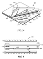
- FIG 3a shows an exploded side view of another embodiment of a detection article 300 according to the present disclosure.
- the article 300 comprises a cover sheet 320, a barrier layer, and a microporous membrane 350, as described herein.
- the barrier layer 340 and microporous membrane 350 further comprise optional tab regions 341 and 351, respectively, as described herein.
- the microporous membrane 350 further comprises optional permeation barrier 353, as described herein.
- the base member 310 comprises a substrate 312, optional adhesive layer 314, and dry coating 316, as described herein.
- the base member further comprises a spacer 318.
- the spacer 318 which comprises an aperture 319, should be constructed from a water-insoluble material.
- the walls of the aperture 319, together with the base member 310 form a sample-receiving well of predetermined size and shape to confine a volume of liquid sample deposited in the article 300.
- the spacer 318 should be thick enough and the aperture 319 large enough to form a well of the desired volume, e.g., 1 milliliter, 2 milliliters, 3 milliliters, 5 milliliters, or more.
- Closed cell polyethylene foam or polystyrene foam are suitable materials for the spacer 318, but any material which is hydrophobic (non-wetting), inert to microorganisms, and, preferably, capable of withstanding a sterilization process may be used.
- the spacer 318 can be coupled to the base member 310, for example, by an adhesive, as described in U.S. Patent No. 4,565,783 .
- the microporous membrane 350 can be configured in the article 300 with a permeation boundary 353 that coincides with the shape, size, and position of the aperture 319.
- the area of the microporous membrane 350 bounded by the permeation boundary 353 may be larger than the area of the aperture 319.
- the permeation boundary 353 can prevent sample liquid from excessively diffusing within the microporous membrane 350.
- the microporous membrane 350 should be positioned such that, during use, at least of portion of the microporous membrane 350 overlays the aperture 319. Preferably, during use, the microporous membrane 350 is positioned such that the microporous membrane 350 substantially overlays the aperture 319. In some embodiments, the area of the microporous membrane 350 is larger than the area of the aperture 319 and the microporous membrane 350 extends beyond the perimeter of the aperture 319.
- the base member 310, microporous membrane 350, barrier layer 340, and cover sheet 320 may be coupled to each other, as shown in FIG. 3a . They may be coupled to each other, for example, with individual segments of double-sided adhesive tape 330. However, other coupling means, described above, may be suitable.
- FIG. 3b shows a top view of the detection article 300 of FIG. 3a .
- the figure shows the cover sheet 320 the tab region 341 of the barrier layer, and the tab region 351 of the microporous membrane.
- FIG. 3b also shows the optional permeation boundary 353, the aperture 319, and a hinge region 305 formed by the double-sided adhesive tape 330 aligned along an edge of the article 300.
- the aperture 319 of FIG. 3b is circular in shape, apertures 319 with other shapes may be suitable.
- the aperture 319 may be in the shape of a square, an oval, a rectangle, a hexagon, an octagon, or it may be an irregular shape.
- FIG. 3c shows a top perspective view of the article 300 of FIG 3a .
- the article 300 comprises a base member 310 that includes a first substrate 112, optional first adhesive layer 114, first dry coating 316 and spacer 318. Also shown in FIG. 3c are the microporous membrane 350, the barrier layer 340, and the cover sheet 320 that includes a second substrate 322, an optional second adhesive layer 324, and a second dry coating 326.
- FIG. 4 shows an exploded side view of another embodiment of a detection article 400 according to the present disclosure.
- the article 400 comprises a barrier layer 440, a cover sheet 420, and a membrane carrier 455 supporting a microporous membrane 450, all as described herein.
- the article further comprises a base member 410 that includes a spacer 418 with an aperture 419, as described herein.
- the microporous membrane 450 can be configured in the article 400 such that the area of the microporous membrane 450 is coextensive with the aperture 419. In some embodiments, the area of the microporous membrane 450 may be smaller than the area of the aperture 419. In some embodiments, the area of the microporous membrane 450 may be smaller than the area of the aperture 419.
- the microporous membrane 450 should be positioned such that, during use, at least of portion of the microporous membrane 450 overlays the aperture 419. Preferably, during use, the microporous membrane 450 is positioned such that the microporous membrane 450 substantially overlays the aperture 419. In some embodiments, the area of the microporous membrane 450 is larger than the area of the aperture 419 and the microporous membrane 450 extends beyond the perimeter of the aperture 419.
- the present disclosure provides a method to detect a microorganism in a liquid sample.
- the method comprises providing a liquid sample suspected of containing a microorganism and any embodiment of a detection article described herein.
- the article comprises a base member comprising a first dry coating that includes a cold water-soluble gelling agent, a microporous membrane, a cover sheet comprising a second dry coating that includes a detection reagent, and a removable barrier layer that forms a fluid barrier between the microporous membrane and the cover sheet.
- the microporous membrane is disposed between the base member and the barrier layer. Further steps of the method are shown in FIG. 5 .
- the liquid sample may be mixed or diluted with a nutrient to facilitate the growth of a microorganism (not shown).
- the liquid sample may be mixed or diluted with a selective agent or a detection reagent (not shown).
- the liquid sample may be mixed or diluted with any combination of nutrient, a selective agent, and a detection reagent.
- the nutrient, selective agent, and/or detection reagent can be added to the liquid sample when the detection article does not comprise a nutrient, selective agent, and/or detection reagent.
- the nutrient, selective agent, and/or detection reagent can be added to the liquid sample even though the detection article comprises a nutrient, selective agent, and/or detection reagent.
- the method further comprises the process 581 of contacting a predetermined amount of the liquid sample with the base member.
- the first dry coating of the base member is exposed. This can be accomplished, for example, by placing an article (see, for example, article 100 of FIGS. 1a and 1c ) onto a relatively level surface and lifting the microporous membrane to expose the first dry coating. The microporous membrane can be grasped by the tab region, if present.
- a predetermined volume e.g., 1 mL, 2 mL, 3 mL, 5 mL
- liquid sample is transferred (e.g., poured or pipetted) onto the first dry coating, thereby contacting the first dry coating.
- the liquid sample can be deposited into a sample-receiving well formed by the aperture in a spacer that is coupled to the base member comprising the first dry coating.
- the method further comprises the process 582 of contacting the microporous membrane with the sample.
- Contacting the microporous membrane with the liquid sample causes at least a portion of the liquid sample to migrate into the microporous membrane, forming a hydrated region.
- Contacting the microporous membrane with the liquid sample can be accomplished, for example, simply by lowering the microporous membrane that was lifted to expose the dry coating.
- the process 582 optionally may further comprise using an inoculum spreading device (e.g., a spreader used to inoculate PETRIFILM plates; available from 3M Company, St. Paul, MN) to distribute the liquid sample across a selected portion (e.g., a pre-measured area) of the first dry coating and the microporous membrane.
- an inoculum spreading device e.g., a spreader used to inoculate PETRIFILM plates; available from 3M Company, St. Paul, MN
- the method further comprises the process 583 of incubating the article for a first period of time.
- the first incubation provides the conditions (i.e., time, temperature) to facilitate the growth of a microorganism.
- the incubation temperature may be selected according to the microorganism to be detected. For example, if a yeast or mold is to be detected, the first incubation temperature typically may be from about room temperature (ca. 23° C) to about 32° C. For example, if a bacterium is to be detected, the first incubation temperature typically may be from about room temperature to about 45° C.
- the first incubation period may be as short as about one hour. In some embodiments, the first incubation is less than about 4 hours (e.g., less than about 2 hours, less than about 3 hours, or less than about 4 hours. In some embodiments, the first incubation period is less than about 8 hours (e.g., less than about 5 hours, less than about 6 hours, less than about 7 hours, or less than about 8 hours). In some embodiments, the first incubation is less than about 12 hours (e.g., about 9 hours, about 10 hours, about 11 hours, or about 12 hours.
- the first incubation period is less than or equal to about 15 hours (e.g., less than about 13 hours, less than about 14 hours, or less than about 15 hours. In some embodiments, the first incubation period is up to 48 hours (e.g., less than about 24 hours, less than about 36 hours, or less than about 48 hours.
- the method further comprises the process 584 of repositioning the barrier layer.
- the barrier layer is repositioned to provide contact between at least a portion of the hydrated region of microporous membrane and at least a portion of the second dry coating.
- the barrier layer is repositioned to provide contact between the entire hydrated region of the microporous membrane and the second dry coating.
- the barrier layer may be repositioned, for example, by twisting or folding the barrier layer to provide contact between the hydrated region and the second dry coating.
- the barrier layer can be removed from the detection article (i.e., the barrier layer is loosely inserted in the article or is detachably attached to the article) to provide contact between the hydrated region of the microporous membrane and the second dry coating.
- Contact between the hydrated region of the microporous membrane and the second dry coating permits hydration of the second dry coating and, thereby, the interaction of an detection reagent, lysis agent, or selective agent in the second dry coating with a microorganism, a component of a microorganism, and/or a metabolic byproduct of a microorganism.
- the interaction can provide a detectable signal.
- the method further comprises the process 585 of incubating the article for a second period of time.
- the incubation temperature for the second period of time can be the same temperature that was used for the first period of time.
- the incubation temperature for the second period of time can be different than the temperature that was used for the first period of time.
- the incubation temperature for the second period of time can be higher than the temperature that was used for the first period of time, thereby reducing the time needed to observe a detectable signal.
- the second incubation period should be an amount of time sufficient to observe a detectable signal.
- the second incubation period preferably is a shorter period than the first incubation period.
- the second incubation period may be as short as about 15 minutes.
- the second incubation is less than about 30 minutes.
- the second incubation period is less than or equal to 4 hours (e.g., less than or equal to about 1 hour, less than or equal to about 2 hours, less than or equal to about 3 hours, or less than or equal to about 4 hours).
- the second incubation is less than or equal to 8 hours (e.g., less than or equal to about 5 hours, less than or equal to about 6 hours, less than or equal to about 7 hours, or less than or equal to about 8 hours).
- the second incubation period is less than or equal to 12 hours (e.g., less than or equal to about 9 hours, less than or equal to about 10 hours, less than or equal to about 11 hours, or less than or equal to about 12 hours).
- the second incubation period is up to about 96 hours (e.g., less than or equal to about 48 hours, less than or equal to 72 hours, less than or equal to about 96 hours.
- the method further comprises the process 586 of observing an indication of the presence or absence of microbial growth.
- the indication may be observable visually and/or by an instrument (e.g., an imaging system) and both types (manual and automated) of detection are contemplated by the present disclosure.
- the nature of the indication of microbial growth generally is dependent upon the detection reagent (or plurality of detection reagents) in the article.
- certain detection reagents e.g. enzyme substrates
- certain detection reagents e.g. pH indicators
- certain detection reagents e.g., pH indicators
- certain detection reagents e.g., polysaccharide or polypeptide polymers
- an indication of the presence of microbial growth comprises the presence of a detectable microbial colony.
- the microbial colony may be detected visually.
- the microbial colony may be detected using an imaging system. Suitable systems for detecting microbial colonies are described, for example, in International Patent Publication No. WO 2005/024047 ; U.S. Patent Application Publication Nos. US 2004/0101954 and US 2004/0102903 ; and U.S. Patent Application No. 61/187,107 (Attorney Docket No. 65250US002) filed on June 15, 2009.
- suitable imaging systems include PETRIFILM Plate Reader (PPR), available from 3M Company (St. Paul, MN), the PETRISCAN Colony Counter available from Spiral Biotech (Norwood, MA), and PROTOCOL and ACOLYTE plate scanners available from Synbiosis (Cambridge, U.K.)
- an indication of the presence of microbial growth comprises the presence of a reaction, detected visually or by instrument, associated with a non-visually-detectable microbial colony.
- the method can further comprise enumerating microorganisms.
- the microorganisms can be enumerated by counting the number of discrete colonies in the article.
- the microorganisms can be enumerated by counting the number of discrete reactions (e.g., colored zones, fluorescent zones, clear zones) that are associated with non-visually-detectable colonies in the article.
- Enumerating microorganisms may comprise using an imaging system to enumerate microorganisms.
- Observing an indication of the presence or absence of microbial growth may comprise obtaining an image of the article. Observing an indication of the presence or absence of microbial growth may further comprise printing, displaying, or analyzing the image.
- An annular gasket was die-cut from biaxially-oriented polypropylene (BOPP, 1.6 mil (0.04mm) thickness) film coated with a thin layer of water-insoluble adhesive (96 wt. % iso-octyl acrylate and 4 wt. % acrylic acid).
- the outer diameter of the gasket was approximately 52.5 mm and the inner diameter of the gasket was approximately 45 mm.
- a circular hole (approximately 44 mm diameter) was die cut from a rectangular sheet (approximately 75 mm by 95 mm) of BOPP (0.04 mm thickness).
- a nylon membrane filter (47mm, 0.45 mm nominal pore size, obtained from Alltech Associates (Deerfield, IL) was centered over the hole on the adhesive-coated side of the BOPP sheet. The adhesive side of the gasket was centered over the outer edge of the membrane filter and was pressed against the filter and the BOPP sheet, sealing the edge of the membrane filter to the BOPP sheet.
- a base member was prepared as follows.
- a plastic film (Microamp Optical Adhesive Film, part number 4311971 from Applied Biosystems, Foster City, CA) comprising silicone adhesive on one major surface was powder coated (on the adhesive surface) was powder coated with a combination of Meyprogat Guar (M150) and Standard Methods Nutrients Broth at a ratio of 2:1, as described in U.S. Patent No. 4,565,783 .
- the composition of the Standard Methods Nutrients Broth is listed in Table 1.
- the coating weight of the powder was approximately 8 grains per 24 square inches.
- a foam spacer (polystyrene capliner foam, 0.5 mm thick, American Fuji Seal Inc., Bardstown, KY) with a thin layer of water-insoluble adhesive on one side and a circular aperture of about 5 cm was laminated to the coated side of the base member.
- Table 1 Standard Methods Nutrients Broth Formulation. All components were added as powders and thoroughly mixed before use.
- Component Weight Percent Pancreatic digest of casein 22.7 Yeast extract 15.9 Sodium pyruvate 45.5 Dextrose 4.1 Potassium phosphate, dibasic 9.0 Potassium phosphate, monobasic 2.8 Sodium carbonate A small amount of sodium carbonate was added such that, when dissolved in deionized water, the mixture had a pH approximately 7.0.
- a cover sheet was prepared.
- Microamp Optical Adhesive Film with a thin layer of transfer adhesive was powder coated with a mixture of Standard Methods Nutrients broth and 0.2% wt/wt Triphenyl Tetrazolium Chloride. The coating weight of this mixture was approximately 8 grains per 24 square inches.
- a multilayer detection article was prepared as follows. The base member was placed on a level surface with the coated side facing up. The microporous membrane carrier was placed onto the base member with the gasket side facing away from the base member. The membrane was centered over the circular aperture in the spacer of the nutrient film. A barrier layer of BOPP (approximately 75 mm by 95 mm by 0.4 mm thick) was placed over the membrane layer. The cover sheet was placed over the barrier layer with the coated side of the cover sheet facing the barrier layer. The four-layer stack of films was then stapled along one side.
- BOPP approximately 75 mm by 95 mm by 0.4 mm thick
- a detection article was made as in Example 1, with the exception that the membrane carrier was made from a BOPP film that did not include a thin layer of adhesive on one side.
- the detection article was inoculated with Staphylococcus aureus ATCC 6538 (1mL of 100CFU/mL solution) and incubated at 37 C for 6 hours.
- the barrier film was then removed and incubation continued at 37 C until 24 hours after inoculation.
- Individual red colonies were visible through the base member.
- a reddish area of growth was also visible through the cover sheet, although the colonies were not as sharply defined as when viewed through the base member. Wetting of the microporous membrane by the liquid sample was observed. The colonies were photographed with a digital camera.
- Example 2 The detection articles of Example 2 was inoculated with 100 colony forming units of Staphylococcus aureus (ATCC 6538) and incubated at 37 C. After 6 hours and 8 hours of incubation, respectively, individual articles were removed from the incubator and the barrier film was removed. After removal of the barrier films, the articles were incubated at 37 C until 24 hours after inoculation. Red colonies were observed in the articles.
- Staphylococcus aureus ATCC 6538
- Example 1 The detection articles of Example 1 inoculated with 100 colony forming units (CFU) of Pseudomonas aeruginosa (ATCC 9027) and incubated at 37 C for 6 to 8 hours, respectively. The barrier film was removed and incubation continued at 37 C until 24 hours after inoculation. Red colonies were observed in the articles.
- CFU colony forming units
- a detection article was constructed as in Example 2 and was inoculated with Pseudomonas fragi (ATCC 51821) at a concentration of about 100 colony forming units (Example 6).
- a second detection article was constructed as in Example 2 and was inoculated with Microbacterium esteraromaticum (ATCC 51822) at a concentration of about 100 colony forming units (Example 7).
- 3M PETRIFILM Aerobic Count plates available from 3M Company, St. Paul, MN
Landscapes
- Health & Medical Sciences (AREA)
- Life Sciences & Earth Sciences (AREA)
- Chemical & Material Sciences (AREA)
- Engineering & Computer Science (AREA)
- Organic Chemistry (AREA)
- Immunology (AREA)
- Zoology (AREA)
- Wood Science & Technology (AREA)
- Bioinformatics & Cheminformatics (AREA)
- Biochemistry (AREA)
- Microbiology (AREA)
- Biotechnology (AREA)
- Biomedical Technology (AREA)
- General Health & Medical Sciences (AREA)
- Molecular Biology (AREA)
- General Engineering & Computer Science (AREA)
- Analytical Chemistry (AREA)
- Genetics & Genomics (AREA)
- Urology & Nephrology (AREA)
- Hematology (AREA)
- Physics & Mathematics (AREA)
- Proteomics, Peptides & Aminoacids (AREA)
- Sustainable Development (AREA)
- General Physics & Mathematics (AREA)
- Tropical Medicine & Parasitology (AREA)
- Virology (AREA)
- Cell Biology (AREA)
- Biophysics (AREA)
- Food Science & Technology (AREA)
- Medicinal Chemistry (AREA)
- Toxicology (AREA)
- Pathology (AREA)
- Clinical Laboratory Science (AREA)
- Measuring Or Testing Involving Enzymes Or Micro-Organisms (AREA)
- Apparatus Associated With Microorganisms And Enzymes (AREA)
Description
- When surfaces become contaminated with bacteria, fungi, yeasts, viruses, or other microorganisms, or "microbes," sickness (morbidity) and, sometimes, death (mortality) may result. This is particularly true when surfaces in food processing plants and healthcare facilitates (e.g., hospitals) become contaminated with microorganisms.
- In food processing plants, surfaces (e.g., solid surfaces, equipment surfaces, protective clothing, etc.) may become contaminated. Such contamination may be caused by or transferred to meat or other foods. In healthcare facilities, microbes may be released onto surfaces (e.g., solid surfaces, equipment surfaces, clothing, etc.) from infected individuals or otherwise. Once a surface becomes contaminated with microbes, contact with the contaminated surface may easily and readily transfer microbes to other locations, such as another surface, an individual, equipment, food, or the like.
- As is well known, microbial contamination and transfer in certain environments may pose significant health risks. For example, the food that leaves a contaminated food processing plant will subsequently be eaten, and may cause sickness and, possibly, death. Microorganisms such as Listeria monocytogenes, Salmonella enteriditis, and Escherichia coli O157:H7 are of particular concern.
- Microbial contamination is of concern in healthcare facilities since some of the patients of such facilities often suffer from infections by pathogenic microbes and, thus, bring the pathogenic microbes into such facilities. Further, many of those who are present in such facilities (e.g., patients) are sick and may be immunologically compromised. These individuals are, thus, at increased risk of becoming sick from infection by the contaminating microbes.
- The invention is disclosed according to the appended claims.
- The present disclosure relates to articles and methods that are used to detect a microorganism. In particular this disclosure relates to a multi-layer detection article that can be used to permit the growth of microorganisms for a limited period of time before repositioning or removing one of the layers to expose the microorganisms to a detection reagent.
- In one aspect, the present disclosure provides an article for detecting or enumerating microorganisms in a sample. The article can comprise a base member, a microporous membrane, a cover sheet, and a barrier layer. The base member can comprise a self-supporting water impervious substrate with upper and lower major surfaces. The upper major surface of the base member can comprise a first dry coating that includes a cold water-soluble gelling agent. The cover sheet can comprise a second dry coating that includes a detection reagent. The barrier layer can be configured to form a fluid barrier between the microporous membrane and the cover sheet. The microporous membrane can be disposed between the base member and the barrier layer.
- In any of the above disclosures, the article further can comprise a spacer. The spacer can comprise an aperture. The spacer can be coupled to the base member to form a sample-receiving well.
- In any of the above disclosure , the cover sheet can be attached to the base member. In any of the above embodiments, the microporous membrane can be attached to the base member. In any of the above embodiments, the barrier layer can be attached to the base member. In any of the above embodiments, the barrier layer can be detachably attached to the base member.
- In any of the above disclosures , the microporous membrane can comprise a material selected from the group consisting of polyethersulfone, nylon, polycarbonate, polyester, cellulose acetate, mixed cellulose esters, polyvinylidene fluoride, nitrocellulose, a ceramic, a derivative of any of the foregoing, and a combination of any two or more of the foregoing.
- In any of the above disclosures, the microporous membrane further can comprise a permeation boundary. In any of the above disclosures , the article further can comprise a nutrient medium. In any of the above disclosures, the article further can comprise a selective agent. In any of the above disclosures, the article further can comprise a plurality of detection reagents. In any of the above disclosures, at least two of the plurality of detection reagents can differentiate at least two types of microorganisms.
- In any one of the above disclosures , the cover sheet further can comprise a cold water-soluble gelling agent.
- In another aspect, the present disclosure provides a method of detecting the presence or absence of a microorganism in a sample. The method can comprise providing a liquid sample suspected of containing a microorganism and a detection article. The detection article can comprise a base member, a microporous membrane, a cover sheet, and a barrier layer that forms a fluid barrier between the microporous membrane and the cover sheet. The base member can comprise a first dry coating that includes a cold water-soluble gelling agent. The cover sheet can comprise a second dry coating that includes a detection reagent. The microporous membrane can be disposed between the base member and the barrier layer. The method further can comprise contacting a predetermined amount of the sample with the first dry coating. The method further can comprise contacting the microporous membrane with the sample. The method further can comprise incubating the article for a first period of time. The method further can comprise repositioning the barrier layer to provide contact between the cover sheet and the microporous membrane. The method further can comprise incubating the article for a second period of time and observing an indication of the presence or absence of microbial growth.
- In any of the above disclosures of the method, repositioning the barrier layer can comprise removing the barrier layer from the article.
- In any of the above disclosures of the method, the article further can comprise a spacer that forms a sample-receiving well with the base member. In these embodiments, contacting a predetermined amount of the sample with the first dry coating can comprise transferring the sample into the sample-receiving well.
- In any of the above of the method, the method further can comprise mixing the sample with a nutrient, a selective agent, a detection reagent, or a combination of any two or more of the foregoing.
- In any of the above of the method, the first period of time can be about one hour to about 48 hours.
- In any of the above disclosures of the method, the second period of time can be about fifteen minutes to about ninety-six hours.
- In any of the above disclosures of the method, at least a portion of the first dry coating can comprise a plurality of detection reagents. In these embodiments, observing an indication of microbial growth can comprise detecting and differentiating two or more types of microorganisms.
- In any of the above disclosures of the method, observing an indication of the presence or absence of microbial growth can comprise enumerating at least one type of microorganism. In any of the above disclosures of the method, observing an indication of the presence or absence of microbial growth can comprise obtaining an image of the article. In any of the above embodiments of the method, observing an indication of the presence or absence of microbial growth further can comprise printing, displaying, or analyzing the image.
- The words "preferred" and "preferably" refer to embodiments of the invention that may afford certain benefits, under certain circumstances. However, other embodiments may also be preferred, under the same or other circumstances. Furthermore, the recitation of one or more preferred embodiments does not imply that other embodiments are not useful, and is not intended to exclude other embodiments from the scope of the invention.
- As used herein, "a," "an," "the," "at least one," and "one or more" are used interchangeably. Thus, for example, a sample comprising "a" microorganism can be interpreted to mean that the sample can include "one or more" microorganisms.
- The term "and/or" means one or all of the listed elements or a combination of any two or more of the listed elements.
- Also herein, the recitations of numerical ranges by endpoints include all numbers subsumed within that range (e.g., 1 to 5 includes 1, 1.5, 2, 2.75, 3, 3.80, 4, 5, etc.).
- The above summary of the present invention is not intended to describe each disclosed disclosure or every implementation of the present invention. The description that follows more particularly exemplifies illustrative embodiments. In several places throughout the application, guidance is provided through lists of examples, which examples can be used in various combinations. In each instance, the recited list serves only as a representative group and should not be interpreted as an exclusive list.
- The invention will be further explained with reference to the drawing figures listed below, where like structure is referenced by like numerals throughout the several views.
-
Figure 1a is an exploded side view of one embodiment of a detection article comprising a microporous membrane according to the present disclosure. -
Figure 1b is a top view of the detection article ofFigure 1a . -
Figure 1c is a top perspective view, partially in section, of the detection article ofFigure 1a . -
Figure 2 is an exploded side view of one embodiment of a detection article comprising a microporous membrane coupled to a membrane carrier according to the present disclosure. -
Figure 3a is an exploded side view of one embodiment of a detection article comprising a spacer and a microporous membrane according to the present disclosure. -
Figure 3b is a top view of the detection article ofFigure 3a . -
Figure 3c is a top perspective view, partially in section, of the detection article ofFigure 3a . -
Figure 4 is an exploded side view of one embodiment of a detection article comprising a spacer and a microporous membrane coupled to a membrane carrier according to the present disclosure. -
Figure 5 is a block diagram of one embodiment of a method to detect a microorganism in a liquid sample according to the present disclosure. - Before any embodiments of the invention are explained in detail, it is to be understood that the invention is not limited in its application to the details of construction and the arrangement of components set forth in the following description or illustrated in the accompanying drawings. The invention is capable of other embodiments and of being practiced or of being carried out in various ways. Also, it is to be understood that the phraseology and terminology used herein is for the purpose of description and should not be regarded as limiting. The use of "including," "comprising," "containing," or "having" and variations thereof herein is meant to encompass the items listed thereafter and equivalents thereof as well as additional items. Unless specified or limited otherwise, the terms "supported," and "coupled" and variations thereof are used broadly and encompass both direct and indirect supports and couplings. It is to be understood that other embodiments may be utilized and structural or logical changes may be made without departing from the scope of the present disclosure. Furthermore, terms such as "front," "rear," "top," "bottom," and the like are only used to describe elements as they relate to one another, but are in no way meant to recite specific orientations of the apparatus, to indicate or imply necessary or required orientations of the apparatus, or to specify how the invention described herein will be used, mounted, displayed, or positioned in use.
- The present disclosure is generally directed to methods and articles for detecting a microorganism in a liquid sample. The multi-layer detection articles provide i) a repositionable or removable barrier layer configured to control the exposure of a growing microorganism to a detection reagent and/or a selective agent and ii) a microporous membrane to prevent direct contact between microorganisms, and progeny thereof, present in the liquid sample and the barrier layer. Preventing direct contact between the microorganisms and the barrier layer obviates the possibility of spreading microorganisms within and/or removing microorganisms from the article when the barrier layer is repositioned or removed from the article.
- The inventive multilayer articles of the present disclosure permit the use of relatively high concentrations of a detection reagent in order to reduce the amount of time needed to detect a microorganism. The presence of a barrier layer in the article prevents the exposure of microorganisms to the detection reagent (which may be present in an amount that could be inhibitory or toxic to the microorganisms) during a first incubation period. After the first incubation period, the barrier layer can be repositioned or removed, thereby exposing the microorganisms, if present, to the detection reagent. The articles of the present disclosure can comprise an optional lysis agent and/or selective agent that may also be sequestered by the barrier layer from contact with the microorganisms during the first incubation period.
- The inventive articles and methods permit the use of diffusible detection reagents. When used in traditional articles (e.g., agar petri dishes), diffusible detection reagents (e.g., chromogenic or fluorogenic enzyme substrates, described below, that are hydrolyzed to a water-soluble, detectable product) can spread laterally through the detection device as large, colored or fluorescent zones. These zones may overlap two or more microorganism colonies, making it difficult to determine whether the zone was produce by only one or by more than one of the colonies. Providing an article that permits growth of microorganisms before they are exposed to the diffusible detection reagent, the user can reduce the amount of time that the microorganisms are exposed to the reagent, thereby minimizing the diffusion of the indicator and reducing the size of the corresponding colored or fluorescent zones. Thus, the inventive articles and methods improve the resolution of more than one microorganism colonies as compared to traditional articles and methods.
- Unless otherwise defined, all technical and scientific terms used herein have the same meaning as commonly understood by one of ordinary skill in the art to which this invention belongs. Methods and materials similar or equivalent to those described herein can be used in the practice of the present invention, and exemplified suitable methods and materials are described below. For example, methods may be described which comprise more than two steps. In such methods, not all steps may be required to achieve a defined goal and the invention envisions the use of isolated steps to achieve these discrete goals. In addition, the materials, methods, and examples are illustrative only and not intended to be limiting.
- "Target microorganism", as used herein, refers to a particular microorganism (i.e., a species of microorganism) or a particular group of microorganisms (e.g., a particular genus of microorganisms, coliform bacteria, antibiotic-resistant bacteria) to be detected.
- One aspect of the present invention is that it may be used to detect organisms present on a wide variety of surfaces. The devices and methods of the present invention may be used for a variety of applications where it is desirable to detect the presence or absence of microorganisms in a sample; including, but not limited to, food samples (e.g. raw materials, in-process food materials, finished products), surfaces (e.g., environmental surfaces, food processing surfaces, equipment), water (e.g., surface water, process water), and beverages (e.g., raw milk, pasteurized milk, juice). The samples may consist substantially of solid, semi-solid, gelatinous, or liquid material, alone or in various combinations. The devices of the invention, as well as the inventive methods, may be used to determine, qualitatively or quantitatively, the presence of one or more microorganisms of interest.
- An exemplary clinical analyte of interest to detect is Staphylococcus aureus ("S. aureus"). This is a pathogen causing a wide spectrum of infections including: superficial lesions such as small skin abscesses and wound infections; systemic and life threatening conditions such as endocarditis, pneumonia and septicemia; as well as toxinoses such as food poisoning and toxic shock syndrome. Some strains (e.g., Methicillin-Resistant S. aureus or MRSA) are resistant to all but a few select antibiotics.
- Exemplary analytes of interest to detect in food processing areas are members of the genus Listeria. Listeria are classified as gram-positive, rod-shaped bacteria and consist of the species Listeria monocytogenes, L. innocua, L. welshimeri, L. seeligeri, L. ivanovii, and L. grayi. Among these, L. monocytogenes is responsible for the majority of human listeriosis cases and immunocompromised, pregnant women, elderly, and newborns have increased susceptibility to infection. The most common symptoms of listeriosis are septicemia, meningitis, and miscarriages.
- Other microorganisms of particular interest for analytical purposes include prokaryotic and eukaryotic organisms, particularly Gram positive bacteria, Gram negative bacteria, fungi, mycoplasma, and yeast. Particularly relevant organisms include members of the family Enterobacteriaceae, or the family Micrococcaceae or the genera Staphylococcus spp., Streptococcus spp., Pseudomonas spp., Enterococcus spp., Salmonella spp., Legionella spp., Shigella spp. Yersinia spp., Enterobacter spp., Escherichia spp., Bacillus spp., Vibrio spp., Clostridium spp., Corynebacteria spp. as well as, Aspergillus spp., Fusarium spp., and Candida spp. Particularly virulent organisms include Staphylococcus aureus (including resistant strains such as Methicillin Resistant Staphylococcus aureus (MRSA)), S. epidermidis, Streptococcus pneumoniae S. agalactiae, S. pyogenes, Enterococcus faecalis, Vancomycin Resistant Enterococcus (VRE), Vancomycin Resistant Staphylococcus aureus (VRSA), Vancomycin Intermediate-resistant Staphylococcus aureus (VISA), Bacillus anthracis, Pseudomonas aeruginosa, Escherichia coli, Aspergillus niger, A.fumigatus, A. clavatus, Fusarium solani, F. oxysporum, F. chlamydosporum, Vibrio cholera, V. parahemolyticus, Salmonella cholerasuis, S. typhi, S. typhimurium, Candida albicans, C. glabrata, C. krusei, Enterobacter sakazakii, Escherichia. coli 0157, ESBL-containing microorganisms, and multiple drug resistant Gram negative rods (MDR).
- The present disclosure provides articles for detecting the presence or absence of a microorganism in a sample.
FIG. 1a shows an exploded side view of one embodiment of adetection article 100 according to the present disclosure. The article comprises abase member 110 that includes a water imperviousfirst substrate 112, an optional firstadhesive layer 114 adhered to thefirst substrate 112, and a firstdry coating 116. - The
first substrate 112 preferably is self-supporting and does not substantially absorb water. Nonlimiting examples of suitable materials for thefirst substrate 112 include polyester, polypropylene, or polystyrene films. Other suitable materials include paper or cardboard materials that comprise a waterproof (e.g., polymeric) coating. Thefirst substrate 112 may be transparent, translucent, or opaque, depending on whether one wishes to view bacterial colonies through thesubstrate 112. To facilitate the counting of bacterial colonies, thefirst substrate 112 may have a square grid pattern printed thereon as described inU.S. Patent No. 4,565,783 . The materials used to construct thefirst substrate 112 should be relatively inert to microorganisms and, preferably, should be compatible with a sterilization process (e.g., ethylene oxide sterilization). - In some embodiments, the
base member 110 further may comprise an optional firstadhesive layer 114 adhered to a major surface of thefirst substrate 112. Firstadhesive layer 114 may be water-insoluble, should be non-inhibitory to the growth of microorganisms, and should be capable of withstanding the sterilization process, if a sterilization process is used. Preferably, the firstadhesive layer 114 is sufficiently transparent when wet to enable the viewing of bacterial colonies through thefirst substrate 112 coated with theadhesive layer 114. In some embodiments, the firstadhesive layer 114 may comprise a pressure-sensitive adhesive such as a tackified high pressure sensitive iso-octyl acrylate/acrylic acid copolymer adhesive (96 wt. % iso-octyl acrylate and 4 wt. % acrylic acid), for example. - In some embodiments, the
first substrate 112 may comprise a firstadhesive layer 114 that covers an entire major surface of thesubstrate 112. In some embodiments, thefirst substrate 112 may comprise a firstadhesive layer 114 that covers only a portion of a major surface of thesubstrate 112. - The first
dry coating 116 comprises a cold water-soluble gelling agent (e.g., guar gum, xanthan gum, locust bean gum), as described inU.S. Patent No. 4,565,783 . Optionally, thedry coating 116 may further comprise a nutrient medium, a selective agent, a detection reagent, or any combination of two or more of the foregoing. The nutrient medium, selective agent, and/or detection reagent should not substantially interfere with the gelling agent and generally will be chosen based upon the microorganisms to be detected. Nonlimiting examples of suitable nutrients, selective agents and detection reagents to detect microorganisms can be found inU.S. Patent Nos. 4,575,783 ;5,089,413 ;5,443,963 ;5,462,860 ;5,601,998 ;5,635,367 ;5,681,712 ; and5,364,766 . The amounts of nutrient medium, selective agent and/or detection reagent in the firstdry coating 116 are prepared such that, when contacted with a predetermined amount of liquid sample, they facilitate the growth and/or detection of a microorganism. - In some embodiments, the first dry coating 116 (e.g., a dry powder gelling agent; optionally with a dry powdered nutrient, selective agent and/or detection reagent) may be coupled to the
first substrate 112 by adhering thecoating 116 the firstadhesive layer 114, as described inU.S. Patent No. 4,565,783 , for example. In some embodiments, the firstdry coating 116 may be coupled to thefirst substrate 112 by coating a liquid mixture comprising a gelling agent; optionally with a dry powdered nutrient, selective agent and/or detection reagent; onto thefirst substrate 112 or firstadhesive layer 114 and subsequently drying the mixture, as described inU.S. Patent No. 4,565,783 , for example. In some embodiments, thefirst substrate 112 may comprise a firstdry coating 116 that covers an entire major surface of thesubstrate 112. In some embodiments, thefirst substrate 112 may comprise a firstdry coating 116 that covers only a portion of a major surface of thesubstrate 112. - Referring back to
FIG. 1a , thearticle 100 further comprises amicroporous membrane 150. In some embodiments, themicroporous membrane 150, or a portion thereof, is coupled to thebase member 110. In the illustrated embodiment, themicroporous membrane 150 is coupled to thebase member 110 via a strip of double-sidedadhesive tape 130, although a person of ordinary skill in the art will recognize that other coupling means (e.g., adhesives, heat-bonding, ultrasonic welding) may be suitable. Optionally, themicroporous membrane 150 may comprise atab region 151 that extends beyond a peripheral boundary of thebase member 110 and/or thecover sheet 120. - The
microporous membrane 150 can comprise any one of a variety of water-permeable microporous membrane materials known in the art including, for example, cellulosic membranes (e.g., cellulose acetate, mixed cellulose esters, nitrocellulose), nylon, polycarbonate, polyethersulfone, nylon, polyester, polyvinylidene fluoride, ceramic , a derivative of any of the foregoing, and a combination of any two or more of the foregoing.. The nominal pore size of themicroporous membrane 150 is selected according to microorganisms to be detected. For example, a nominal pore size of about 0.05 µm to about 1.2 µm (e.g., 0.05 µm, 0.1 µm, 0.2 µm, 0.45 µm, 0.8 µm, or 1.2 µm), preferably about 0.2 µm to about 0.45 µm, can be used to detect bacteria. In some embodiments, a nominal pore size of about 0.05 µm to about 3 µm (e.g., 0.45 µm, 0.8 µm, 1.2 µm, or 3 µm), preferably about 0.45 µm to about 1.2 µm, can be used to detect yeast and/or molds. - In any embodiment, the
microporous membrane 150 should be configured to form a barrier to prevent the transfer of microorganisms in a liquid sample deposited on thebase member 110 from contacting thebarrier layer 140. In some embodiments, this can be accomplished by selecting the sample volume and/or dimensioning themicroporous membrane 150 such that the liquid sample cannot spread to or beyond the outer margin of themicroporous membrane 150. In some embodiments (as shown inFIG. 1 ), themicroporous membrane 150 can be dimensioned to be at least coextensive with the dimensions of thebase member 110. Coupling themicroporous membrane 150 to thebase member 110, as described above, advantageously can keep themembrane 150 properly positioned to avoid direct contact between the sample and thebarrier layer 140. - The
microporous membrane 150 can further comprise an optionallateral permeation boundary 153 to confine the lateral permeation of liquid to a selected portion of themicroporous membrane 150. Thepermeation boundary 153 comprises an area of themicroporous membrane 150 that has been treated (e.g., a composition has been applied), for example, to restrict the movement of an aqueous sample across and/or through the microporous membrane. For example, a hydrophobic composition (e.g., wax) can be applied in a circular pattern (seeFIG. 1b ), for example, and allowed to penetrate themicroporous membrane 150. The composition may form a barrier that substantially prevents the lateral diffusion of an aqueous liquid through themicroporous membrane 150. Thus, a liquid sample in contact with themicroporous membrane 150 in a region on one side of thepermeation boundary 153 will be substantially prevented from spreading laterally through themicroporous membrane 150 to the region on the other side of the permeation boundary. - The
article 100 further comprises abarrier layer 140. In some embodiments, thebarrier layer 140 is detachably coupled to themicroporous membrane 150, as shown inFIG. 1 . Thebarrier layer 140 may be coupled to themicroporous membrane 150 via a strip of double-sidedadhesive tape 130. Preferably thebarrier layer 140 further comprises a detachment means (e.g., perforation 145) to facilitate the detachment and removal of thebarrier layer 140 from thearticle 100. Optionally, thebarrier layer 140 may comprise atab region 141 that extends beyond a peripheral boundary of thebase member 110 and/or thecover sheet 120. - It is recognized that other coupling means (e.g., adhesives, heat-bonding, ultrasonic welding) may be suitable to attach the
barrier layer 140 to themicroporous membrane 150. It is also recognized that thebarrier layer 140 may be coupled directly to thebase member 110, provided that the microporous membrane is disposed between thebase member 110 and thebarrier layer 140. In an alternative embodiment, certain low-adhesion adhesive mixtures, such as those described inU.S. Patent No. 5,118,750 ; may be used on at least one side of the double-sidedadhesive tape 130 to form detachable attachments between the barrier layer and both themicroporous membrane 150 and thecover sheet 120. In yet another alternative embodiment (not shown), thebarrier layer 140 may be loosely disposed between themicroporous membrane 150 and thecover sheet 120 before and/or after inoculating thearticle 100. - The
barrier layer 140 should be water-resistant. Thebarrier layer 140 is preferably transparent to permit the observation of objects located beneath thebarrier layer 140 and is substantially impermeable to bacteria, water and water vapor. Generally, thebarrier layer 140 can have the same properties asbase member 110. Exemplary materials forbarrier layer 140 include, for example, polypropylene film (e.g., 1.6 mil biaxially-oriented polypropylene (BOPP)) or polyethylene film. Thebarrier layer 140 is shown with an optional extension (tab 141), which facilitates grasping and removing thebarrier layer 140 from thearticle 110. - The
article 100 further comprises acover sheet 120. Thecover sheet 120 preferably is coupled (either directly or indirectly) to thebase member 110. In the illustrated embodiment, thecover sheet 120 is coupled to thebarrier layer 140 via a strip of double-sidedadhesive tape 130. It is recognized that other coupling means (e.g., adhesives, heat-bonding, ultrasonic welding) may be suitable to attach thecover sheet 120 to the microporousmembrane barrier layer 140. It is also recognized that thecover sheet 120 may be coupled directly to thebase member 110, provided that the microporous membrane is disposed between thebase member 110 and thecover sheet 120. Thecover sheet 120 includes a water-impervioussecond substrate 122, an optional secondadhesive layer 124, and a seconddry coating 126. The seconddry coating 126 comprises a detection reagent to detect a microorganism. - The detection reagent may be detected visually and/or by using an automated detector. The automated detector may comprise an imaging system. The detection reagent may be chromogenic, fluorogenic, or luminogenic. In any embodiment, the detection reagent, when contacted with a predetermined amount of liquid sample reaches a concentration sufficient to detect a target microorganism. Advantageously, the amount of the detection reagent in the second
dry coating 126 can be sufficiently high to rapidly detect the presence of a target microorganism even though the high concentration of detection reagent in the liquid sample also inhibits the growth of the target microorganism. In some embodiments, the amount of detection reagent in the seconddry coating 126 is sufficient to detect a target microorganism even though it substantially inhibits the growth of the target microorganism. A relatively higher amount of detection reagent in the second dry 126 coating permits more rapid detection of the target microorganisms than a relatively lower amount of detection reagent even though the relatively higher amount may substantially inhibit growth of the microorganisms. - The detection reagent can be a nonspecific indicator of the type of microorganism present or it can be a specific indicator of the type of microorganism present. Nonlimiting examples of nonspecific detection reagents include pH indicators (e.g., azobenzene pH indicators (e.g., methyl red), sulfonphthalein pH indicators (e.g., bromocresol purple, chlorophenol red, bromthymol blue, bromcresol blue), and anthroquinone pH indicators (e.g., alizarin red s monohydrate 3,4-dihydroxy-9,10-dioxo-2-anthracensulfonic acid, sodium salt)) and redox indicators (e.g., triphenyltetrazolium chloride (TTC), 3-[4,5-dimethylthiazol-2-yl]-2,5-diphenyltetrazolium bromide (MTT), 2,3-bis[2-methoxy-4-nitro-5-sulfopheny]-2H-tetrazolium-5-carboxyanilide inner salt (XTT), Nitro Blue Tetrazolium).
- The detection reagent can be a specific indicator of the type of microorganism present. Specific detection reagents include, for example, substrates for enzymes (e.g., glycosidases, proteases, aminopeptidases, phosphatases, esterases, and the like) that are associated with certain microorganisms or groups of microorganisms.
- The detection reagent may be capable of forming a colored precipitate. A variety of dyes are known that could be incorporated into the methods and devices of the present disclosure, including indolyl-containing dyes including, but not limited to, 5-bromo-4-chloroindolyl phosphate or disodium salts of that compound, 5-bromo-4-chloroindolyl pyranoside or disodium salts of that compound, including 5-bromo-4-chloro-3 indolyl-β-D-glucuronic acid, 5-bromo-4-chloro-3-indoxyl- β -D-galactoside, 5-bromo-4-chloro-3-indolyl- β -D-glucopyranoside, 6-chloro-3-indolylphosphate, 5-bromo-6-chloro-3-indolylphosphate.
- Preferably, the colored precipitate is blue. Substrates that create a blue colored precipitate include, but are not limited to, 5-bromo-4-chloro-3-indoxyl-N-acetyl- β -D-galactosaminide, 5-bromo-4-chloro-3-indoxyl-N-acetyl- β -D-glucosaminide, 5-bromo-4-chloro-3-indoxyl- β -D-cellobioside, 5-bromo-4-chloro-3- β -D-fucopyranoside, 5-bromo-4-chloro-3-indoxyl- α -D-galactopyranoside, 5-bromo-4-chloro-3-indoxyl- β - galactopyranoside, 5-bromo-4-chloro-3-indoxyl- α -D-glucopyranoside, 5-bromo-4-chloro-3-indoxyl-β-D-glucopyranoside, 5-bromo-4-chloro-3-indoxyl-β-D-glucuronic acid, cyclohexylammonium salt, 5-bromo-4-chloro-3-indoxyl-β-D-glucuronic acid, sodium salt, and 5-bromo-4-chloro-3-indoxyl-β-D-xylopyranoside.
- The dyes can serve as substrates for particular enzymes present within certain types of bacteria. For example, blue-precipitate producing dyes that are substrates for esterases include, but are not limited to, 5-bromo-4-chloro-3-indoxyl butyrate, 5-bromo-4-chloro-3-indoxyl caprylate, and 5-bromo-4-chloro-3-indoxyl palmitate. Substrates for phosphatases include, but are not limited to, 5-bromo-4-chloro-3-indoxyl phosphate di(2-amino-2-methyl-1,3-propanediol) salt, 5-bromo-4-chloro-3-indoxyl phosphate disodium salt, 5-bromo-4-chloro-3-indoxyl phosphate and p-toluidine salt, 5-bromo-4-chloro-3-indoxyl phosphate and the potassium salt.
- Chromogenic dyes that are substrates for glycosidases include, but are not limited to, 3-indoxyl-β-D-galactopyranoside, 3-indoxyl-β-D-glucopyranoside, 3-indoxyl-β-D-glucuronic acid cyclohexylammonium salt, and 3-indoxyl-β-D-glucuronic acid sodium salt. Other chromogenic substrates for phophatases include, but are not limited to, 3-indoxyl phosphate di(2-amino-2-methyl-1,3-propanediol) salt, and 3-indoxyl phosphate disodium salt, 3-indoxyl phosphate p-toluidine salt. Substrates for sulfatases include, but are not limited to, 3-indoxyl sulfate potassium salt.
- Precipitable dyes that produce a magenta color for glycosidases, esterases, phosphatases and sulfatases include, but are not limited to 5-bromo-6-chloro-3-indoxyl-N-acetyl-β-D-glucosaminide, 5-bromo-6-chloro-3-indoxyl-β-D-galactopyranoside, 5-bromo-6-chloro-3-indoxyl-β-D-galactopyranoside, 5-bromo-6-chloro-3-indoxyl-β- D-glucopyranoside, and 5-bromo-6-chloro-3-indoxyl-β-glucuronic acid, cyclohexylammonium salt as substrates for glycosidases; 5-bromo-6-chloro-3-indoxyl butyrate, 5-bromo-6-chloro-3-indoxyl caprylate, and 5-bromo-6-chloro-3-indoxyl palmitate serve as substrates for esterases; 5-bromo-6-chloro-3-indoxyl phosphate, p-toluidine salt for phosphatases and 5-bromo-6-chloro-3-indoxyl sulfate, potassium salt serve as substrates for sulfatases.
- Precipitable dyes that produce a salmon color for glycosidases, esterases and phosphatases include, but are not limited to, 6-chloro-3-indoxyl-β-galactopyranoside, 6-chloro-3-indoxyl-β-D-glucopyranoside, and 6-chloro-3-indoxyl-β-D-glucuronic acid, cyclohexylammonium salt for glycosidases; 6-chloro-3-indoxyl butyrate, 6-chloro-3-indoxyl caprylate, and 6-chloro-3-indoxyl palmitate for esterases; and, 6-chloro-3-indoxyl phosphate, p-toluidine salt for phosphatases.
- Chromogenic substrates that produce a purple color include 5-iodo-3-indoxyl-β -D-galactopyranoside and chromogenic substrates that produce a green color include N-methyl-indoxyl-β-D-galactopyranoside.
- Other precipitable dyes include 4,6-dichloro-N-acetylindol-3-ol, 6-chloroindolyl-β-D-galactoside pentaacetate, 6-chloroindolyl-β-D-galactoside, 6-chloroindoxy-1,3-diacetate, 5-chloro-2-carboxyphenylglycine sodium salt, 4-chloroanthranilic acid, methyl[6-chloro-N-acetylindol-3-yl-(2,3,4-tri-O-acetyl-β-D-glucopyran oside)]uronate, 6-chloroindolyl-β-D-glucopyranoside uronate monocyclohexylammonium salt, chloroindigos reported by Sadler et al., J. Am Chem. Soc. 78:1251-1255, 1956, as well as 4,6-dichloroindolyl-β-D-glucuronide, 6,7-dichloroindolyl-β-D-glucuronide, 6,7-dichloroindolyl-β-D-glucuronide, 4,6,7-trichloroindolyl-β-D-glucuronide, 4,6-dichloroindolyl-β-D-galactoside, 6,7-dichloroindolyl-β-D-galactoside, and 4,6,7-trichloroindolyl-β-D-galactoside.
- Suitable detection reagents further include non-precipitating indicator dyes (i.e., water-soluble dyes that are capable of diffusing in a hydrogel). Non-precipitating indicator dyes include pH indicators (e.g., azobenzene pH indicators, sulfonphthalein pH indicators, and anthroquinone pH indicators, as described herein. Non-precipitating indicator dyes also include chromogenic enzyme substrates that react with an enzyme to release a water-soluble dye (e.g., p-nitrophenyl phosphate or p-nitrophenyl-β-D-glucoside, which each can be hydrolyzed to p-nitrophenol), and fluorogenic enzyme substrates, which can react with an enzyme to release a water-soluble fluorescent dye (e.g. 4-methylumbelliferyl phosphate or 4-methylumbelliferyl-β-D-glucoside, which each can be hydrolyzed to p-nitrophenol).
- A problem with using non-precipitating dyes in traditional articles and methods (e.g., agar petri dish methods) is that the indicator dyes are typically incorporated into the agar and the microorganisms are able to react with the dyes during the entire growth period. This relatively lengthy period of exposure to the indicator dyes permits significant lateral diffusion of the water-soluble products which can result in large zones of indicator dye that overlap two or more colonies. Thus, in the traditional methods, the operator may not be able to distinguish which colony or colonies reacted with the indicator dye.
- In contrast, methods of the present disclosure (described below) include a first incubation period during which the microorganisms, if present are not able to react with the detection reagent. Methods of the present disclosure further include a second incubation period in which the microorganisms, if present, are exposed to the detection reagent. Because the second incubation period can be relatively short (e.g., about 15 minutes, about 30 minutes, about 1 hour, about 2 hours, about 3 hours, about 4 hours, about 6 hours, about 8 hours, or about 10 hours), nonprecpitating indicator dyes do not have enough time to substantially diffuse through the gel formed from the liquid sample and the cold water soluble gelling agent. Advantageously, this permits the use of water-soluble indicator reagents that would diffuse too far from the vicinity of a colony if the indicator reagent was incubated for longer periods of time (e.g., 18 hours, 24 hours, 36 hours, or 48 hours, for example) with the microorganisms in a hydrogel.
- The
second substrate 122 preferably is transparent or translucent, to permit viewing or imaging of bacterial colonies through thesubstrate 122, and does not substantially absorb water. Nonlimiting examples of suitable materials for thesecond substrate 122 include polyester, polypropylene, or polystyrene films. Other suitable materials include paper or cardboard materials that comprise a waterproof (e.g., polymeric) coating. The materials used to construct thesecond substrate 122 should be relatively inert to microorganisms and, preferably, should be compatible with a sterilization process (e.g., ethylene oxide sterilization). - In some embodiments, the
cover sheet 120 further may comprise an optional secondadhesive layer 124 adhered to thesecond substrate 122. Secondadhesive layer 124 may be water-insoluble, should be non-inhibitory to the growth of microorganisms, and should be capable of withstanding the sterilization process, if a sterilization process is used. Preferably, the secondadhesive layer 124 is sufficiently transparent when wet to enable the viewing or imaging of bacterial colonies through thecover sheet 110. In some embodiments, the secondadhesive layer 124 may comprise a pressure-sensitive adhesive such as a tackified high pressure sensitive iso-octyl acrylate/acrylic acid copolymer adhesive (96 wt. % iso-octyl acrylate and 4 wt. % acrylic acid), for example. - The second
dry coating 126 comprises a detection reagent. Optionally, the seconddry coating 126 may further comprise a cold water-soluble gelling agent (e.g., guar gum, xanthan gum, locust bean gum), as described inU.S. Patent No. 4,565,783 ; a nutrient, a lysis agent, a selective agent, or any combination of two or more of the foregoing. The nutrient, selective agent, and/or lysis agent generally will be chosen based upon the microorganisms to be detected. Nonlimiting examples of suitable nutrients, selective agents and detection reagents to detect microorganisms can be found inU.S. Patent Nos. 4,575,783 ;5,089,413 ;5,443,963 ;5,462,860 ;5,601,998 ;5,635,367 ;5,681,712 ; and5,364,766 . - The optional lysis agent can partially or completely lyse a microorganism, allowing for the detection of an internal component (e.g., an enzyme) of the microorganism. Lysis agents include detergents, enzymes (e.g., lysozyme, lysostaphin) and bacteriophage.
- In some embodiments, the second
dry coating 126 may be coupled to thesecond substrate 122 by adhering thecoating 126 to the secondadhesive layer 124, as described inU.S. Patent No. 4,565,783 , for example. In some embodiments, the seconddry coating 126 may be coupled to thesecond substrate 122 by coating a liquid mixture comprising a detection reagent; optionally with a gelling agent (e.g., a cold water soluble gelling agent), a nutrient, a selective agent and/or a lysis reagent; onto thesecond substrate 122 or secondadhesive layer 124 and subsequently drying the mixture, as described inU.S. Patent No. 4,565,783 , for example. - The second
dry coating 126 may include a detection reagent that, when contacted with a predetermined amount of liquid sample reaches a concentration sufficient to detect a target microorganism yet also inhibit the growth of the target microorganism. In some embodiments, the amount of detection reagent in the seconddry coating 126 is sufficient to detect a target microorganism yet also substantially inhibit the growth of the target microorganism. -
FIG. 1b shows a top view of thedetection article 100 ofFIG. 1a . The figure shows thecover sheet 120, thetab region 141 of the barrier layer, and thetab region 151 of the microporous membrane. The figure also shows theoptional permeation boundary 153 and ahinge region 105 formed by the double-sidedadhesive tape 130 aligned along an edge of thearticle 100. -
FIG. 1c shows a top perspective view of thearticle 100 ofFIG 1a . Thearticle 100 comprises abase member 110 that includes afirst substrate 112, optional firstadhesive layer 114, and firstdry coating 116. Also shown inFIG. 1c are themicroporous membrane 150, thebarrier layer 140, and thecover sheet 120 that includes asecond substrate 122, an optional secondadhesive layer 124, and a seconddry coating 126. Themicroporous membrane 150 includes apermeation boundary 153, as described above. -
FIG. 2 shows an exploded side view of another embodiment of adetection article 200 according to the present disclosure. Thearticle 200 comprises abase member 210,barrier layer 240, and coversheet 220, as described above. Thearticle 200 further comprises amembrane carrier 255 that includes amicroporous membrane 250. - The
membrane carrier 255 is disposed between thebase member 210 and thebarrier layer 240. In some embodiments, themembrane carrier 255 is coupled to thebase member 210 and/or barrier layer 240 (e.g., via double-sided adhesive tape 230). Themembrane carrier 250 may be coupled to thebase member 210 and/orbarrier layer 240 by alternative means, as described above. - The
membrane carrier 255 is configured to support amicroporous membrane 250. Themembrane carrier 255 preferably is self-supporting and does not substantially absorb water. Nonlimiting examples of suitable materials for themembrane carrier 255 include polyester, polypropylene, or polystyrene films. Other suitable materials include paper or cardboard materials that comprise a waterproof (e.g., polymeric) coating. Themembrane carrier 255 may be transparent, translucent, or opaque. Themembrane carrier 255 further comprises anaperture 257 that permits fluid communication from thebase member 210 through themicroporous membrane 250 to thecover sheet 220, when thebarrier layer 240 is detached from thearticle 200. Optionally, themembrane carrier 255 may comprise atab region 251 that extends beyond a peripheral boundary of thebase member 210 and/or thecover sheet 220. - The
aperture 257 can be any shape, such as a circle, a square, a rectangle, a hexagon, an octagon, an oval, or an irregular shape, for example. - The
microporous membrane 250 can be dimensioned to be coextensive with theaperture 257. In some embodiments, themicroporous membrane 250 is smaller than theaperture 257. In some embodiments, themicroporous membrane 250 is larger than theaperture 257, as shown inFIG. 2 . The microporous membrane can be dimensioned to provide an area suitable to distribute a predetermined amount of liquid sample. For example, to distribute a 1 milliliter sample, themicroporous membrane 250 can be about 20 cm2 to about 30 cm2. For example, to distribute a 5 milliliter sample, themicroporous membrane 250 can be about 45 cm2. - The
microporous membrane 250 is coupled to the membrane carrier 255 (preferably, by an adhesive) such that the coupling prevents the passage of liquid sample between themembrane carrier 255 and themicroporous membrane 250. Thus, the passage of liquid from one major surface of themicroporous membrane 250 to the other major surface substantially requires the passage of the liquid through themembrane 250. -
FIG 3a shows an exploded side view of another embodiment of adetection article 300 according to the present disclosure. Thearticle 300 comprises acover sheet 320, a barrier layer, and amicroporous membrane 350, as described herein. Thebarrier layer 340 andmicroporous membrane 350 further compriseoptional tab regions microporous membrane 350 further comprisesoptional permeation barrier 353, as described herein. - In this embodiment, the
base member 310 comprises asubstrate 312, optionaladhesive layer 314, anddry coating 316, as described herein. The base member further comprises aspacer 318. Thespacer 318, which comprises anaperture 319, should be constructed from a water-insoluble material. The walls of theaperture 319, together with thebase member 310 form a sample-receiving well of predetermined size and shape to confine a volume of liquid sample deposited in thearticle 300. Thespacer 318 should be thick enough and theaperture 319 large enough to form a well of the desired volume, e.g., 1 milliliter, 2 milliliters, 3 milliliters, 5 milliliters, or more. Closed cell polyethylene foam or polystyrene foam are suitable materials for thespacer 318, but any material which is hydrophobic (non-wetting), inert to microorganisms, and, preferably, capable of withstanding a sterilization process may be used. Thespacer 318 can be coupled to thebase member 310, for example, by an adhesive, as described inU.S. Patent No. 4,565,783 . - In some embodiments, the
microporous membrane 350 can be configured in thearticle 300 with apermeation boundary 353 that coincides with the shape, size, and position of theaperture 319. In some embodiments, the area of themicroporous membrane 350 bounded by thepermeation boundary 353 may be larger than the area of theaperture 319. In these embodiments, thepermeation boundary 353 can prevent sample liquid from excessively diffusing within themicroporous membrane 350. - The
microporous membrane 350 should be positioned such that, during use, at least of portion of themicroporous membrane 350 overlays theaperture 319. Preferably, during use, themicroporous membrane 350 is positioned such that themicroporous membrane 350 substantially overlays theaperture 319. In some embodiments, the area of themicroporous membrane 350 is larger than the area of theaperture 319 and themicroporous membrane 350 extends beyond the perimeter of theaperture 319. - In some embodiments, the
base member 310,microporous membrane 350,barrier layer 340, and coversheet 320 may be coupled to each other, as shown inFIG. 3a . They may be coupled to each other, for example, with individual segments of double-sidedadhesive tape 330. However, other coupling means, described above, may be suitable. -
FIG. 3b shows a top view of thedetection article 300 ofFIG. 3a . The figure shows thecover sheet 320 thetab region 341 of the barrier layer, and thetab region 351 of the microporous membrane.FIG. 3b also shows theoptional permeation boundary 353, theaperture 319, and ahinge region 305 formed by the double-sidedadhesive tape 330 aligned along an edge of thearticle 300. Although theaperture 319 ofFIG. 3b is circular in shape,apertures 319 with other shapes may be suitable. For example, theaperture 319 may be in the shape of a square, an oval, a rectangle, a hexagon, an octagon, or it may be an irregular shape. -
FIG. 3c shows a top perspective view of thearticle 300 ofFIG 3a . Thearticle 300 comprises abase member 310 that includes afirst substrate 112, optional firstadhesive layer 114, firstdry coating 316 andspacer 318. Also shown inFIG. 3c are themicroporous membrane 350, thebarrier layer 340, and thecover sheet 320 that includes asecond substrate 322, an optional secondadhesive layer 324, and a seconddry coating 326. -
FIG. 4 shows an exploded side view of another embodiment of adetection article 400 according to the present disclosure. Thearticle 400 comprises abarrier layer 440, acover sheet 420, and amembrane carrier 455 supporting amicroporous membrane 450, all as described herein. The article further comprises abase member 410 that includes a spacer 418 with anaperture 419, as described herein. - The
microporous membrane 450 can be configured in thearticle 400 such that the area of themicroporous membrane 450 is coextensive with theaperture 419. In some embodiments, the area of themicroporous membrane 450 may be smaller than the area of theaperture 419. In some embodiments, the area of themicroporous membrane 450 may be smaller than the area of theaperture 419. - The
microporous membrane 450 should be positioned such that, during use, at least of portion of themicroporous membrane 450 overlays theaperture 419. Preferably, during use, themicroporous membrane 450 is positioned such that themicroporous membrane 450 substantially overlays theaperture 419. In some embodiments, the area of themicroporous membrane 450 is larger than the area of theaperture 419 and themicroporous membrane 450 extends beyond the perimeter of theaperture 419. - The present disclosure provides a method to detect a microorganism in a liquid sample. The method comprises providing a liquid sample suspected of containing a microorganism and any embodiment of a detection article described herein. The article comprises a base member comprising a first dry coating that includes a cold water-soluble gelling agent, a microporous membrane, a cover sheet comprising a second dry coating that includes a detection reagent, and a removable barrier layer that forms a fluid barrier between the microporous membrane and the cover sheet. The microporous membrane is disposed between the base member and the barrier layer. Further steps of the method are shown in
FIG. 5 . - Optionally, the liquid sample may be mixed or diluted with a nutrient to facilitate the growth of a microorganism (not shown). Optionally, the liquid sample may be mixed or diluted with a selective agent or a detection reagent (not shown). In some embodiments, the liquid sample may be mixed or diluted with any combination of nutrient, a selective agent, and a detection reagent. In some embodiments, the nutrient, selective agent, and/or detection reagent can be added to the liquid sample when the detection article does not comprise a nutrient, selective agent, and/or detection reagent. In some embodiments, the nutrient, selective agent, and/or detection reagent can be added to the liquid sample even though the detection article comprises a nutrient, selective agent, and/or detection reagent.
- The method further comprises the
process 581 of contacting a predetermined amount of the liquid sample with the base member. Initially, the first dry coating of the base member is exposed. This can be accomplished, for example, by placing an article (see, for example,article 100 ofFIGS. 1a and1c ) onto a relatively level surface and lifting the microporous membrane to expose the first dry coating. The microporous membrane can be grasped by the tab region, if present. - After lifting the microporous membrane to expose the first dry coating, a predetermined volume (e.g., 1 mL, 2 mL, 3 mL, 5 mL) of liquid sample is transferred (e.g., poured or pipetted) onto the first dry coating, thereby contacting the first dry coating. In some embodiments, the liquid sample can be deposited into a sample-receiving well formed by the aperture in a spacer that is coupled to the base member comprising the first dry coating.
- The method further comprises the
process 582 of contacting the microporous membrane with the sample. Contacting the microporous membrane with the liquid sample causes at least a portion of the liquid sample to migrate into the microporous membrane, forming a hydrated region. Contacting the microporous membrane with the liquid sample can be accomplished, for example, simply by lowering the microporous membrane that was lifted to expose the dry coating. Theprocess 582 optionally may further comprise using an inoculum spreading device (e.g., a spreader used to inoculate PETRIFILM plates; available from 3M Company, St. Paul, MN) to distribute the liquid sample across a selected portion (e.g., a pre-measured area) of the first dry coating and the microporous membrane. - The method further comprises the
process 583 of incubating the article for a first period of time. The first incubation provides the conditions (i.e., time, temperature) to facilitate the growth of a microorganism. A person of ordinary skill in the relevant art will recognize that the incubation temperature may be selected according to the microorganism to be detected. For example, if a yeast or mold is to be detected, the first incubation temperature typically may be from about room temperature (ca. 23° C) to about 32° C. For example, if a bacterium is to be detected, the first incubation temperature typically may be from about room temperature to about 45° C. - According to the present disclosure, the first incubation period may be as short as about one hour. In some embodiments, the first incubation is less than about 4 hours (e.g., less than about 2 hours, less than about 3 hours, or less than about 4 hours. In some embodiments, the first incubation period is less than about 8 hours (e.g., less than about 5 hours, less than about 6 hours, less than about 7 hours, or less than about 8 hours). In some embodiments, the first incubation is less than about 12 hours (e.g., about 9 hours, about 10 hours, about 11 hours, or about 12 hours. In some embodiments, the first incubation period is less than or equal to about 15 hours (e.g., less than about 13 hours, less than about 14 hours, or less than about 15 hours. In some embodiments, the first incubation period is up to 48 hours (e.g., less than about 24 hours, less than about 36 hours, or less than about 48 hours.
- The method further comprises the
process 584 of repositioning the barrier layer. The barrier layer is repositioned to provide contact between at least a portion of the hydrated region of microporous membrane and at least a portion of the second dry coating. Preferably, the barrier layer is repositioned to provide contact between the entire hydrated region of the microporous membrane and the second dry coating. The barrier layer may be repositioned, for example, by twisting or folding the barrier layer to provide contact between the hydrated region and the second dry coating. In a preferred embodiment, the barrier layer can be removed from the detection article (i.e., the barrier layer is loosely inserted in the article or is detachably attached to the article) to provide contact between the hydrated region of the microporous membrane and the second dry coating. - Contact between the hydrated region of the microporous membrane and the second dry coating permits hydration of the second dry coating and, thereby, the interaction of an detection reagent, lysis agent, or selective agent in the second dry coating with a microorganism, a component of a microorganism, and/or a metabolic byproduct of a microorganism. The interaction can provide a detectable signal.
- The method further comprises the
process 585 of incubating the article for a second period of time. In some embodiments, the incubation temperature for the second period of time can be the same temperature that was used for the first period of time. In some embodiments, the incubation temperature for the second period of time can be different than the temperature that was used for the first period of time. Advantageously, the incubation temperature for the second period of time can be higher than the temperature that was used for the first period of time, thereby reducing the time needed to observe a detectable signal. - According to the present disclosure, the second incubation period should be an amount of time sufficient to observe a detectable signal. In some embodiments, the second incubation period preferably is a shorter period than the first incubation period. In combination with any of the above first incubation periods, the second incubation period may be as short as about 15 minutes. In combination with any of the above first incubation periods, the second incubation is less than about 30 minutes. In combination with any of the above first incubation periods, the second incubation period is less than or equal to 4 hours (e.g., less than or equal to about 1 hour, less than or equal to about 2 hours, less than or equal to about 3 hours, or less than or equal to about 4 hours). In combination with any of the above first incubation periods, the second incubation is less than or equal to 8 hours (e.g., less than or equal to about 5 hours, less than or equal to about 6 hours, less than or equal to about 7 hours, or less than or equal to about 8 hours). In combination with any of the above first incubation periods, the second incubation period is less than or equal to 12 hours (e.g., less than or equal to about 9 hours, less than or equal to about 10 hours, less than or equal to about 11 hours, or less than or equal to about 12 hours). combination with any of the above first incubation periods, the second incubation period is up to about 96 hours (e.g., less than or equal to about 48 hours, less than or equal to 72 hours, less than or equal to about 96 hours.
- The method further comprises the
process 586 of observing an indication of the presence or absence of microbial growth. The indication may be observable visually and/or by an instrument (e.g., an imaging system) and both types (manual and automated) of detection are contemplated by the present disclosure. - The nature of the indication of microbial growth generally is dependent upon the detection reagent (or plurality of detection reagents) in the article. For example, certain detection reagents (e.g. enzyme substrates) produce a detectable colored or fluorescent product when they interact with a microbe or a component thereof. For example, certain detection reagents (e.g., pH indicators) produce a detectable change in color or fluorescence in the presence of acidic or basic metabolic products of microorganisms. For example, certain detection reagents (e.g., polysaccharide or polypeptide polymers) are relatively opaque in their native state and become relatively transparent when degraded by microorganisms or components thereof.
- In some embodiments, an indication of the presence of microbial growth comprises the presence of a detectable microbial colony. The microbial colony may be detected visually. The microbial colony may be detected using an imaging system. Suitable systems for detecting microbial colonies are described, for example, in International Patent Publication No.
WO 2005/024047 ; U.S. Patent Application Publication Nos.US 2004/0101954 andUS 2004/0102903 ; andU.S. Patent Application No. 61/187,107 - In some embodiments, an indication of the presence of microbial growth comprises the presence of a reaction, detected visually or by instrument, associated with a non-visually-detectable microbial colony.
- In any one of the above embodiments, the method can further comprise enumerating microorganisms. In some embodiments, the microorganisms can be enumerated by counting the number of discrete colonies in the article. In some embodiments, the microorganisms can be enumerated by counting the number of discrete reactions (e.g., colored zones, fluorescent zones, clear zones) that are associated with non-visually-detectable colonies in the article. Enumerating microorganisms may comprise using an imaging system to enumerate microorganisms.
- Observing an indication of the presence or absence of microbial growth may comprise obtaining an image of the article. Observing an indication of the presence or absence of microbial growth may further comprise printing, displaying, or analyzing the image.
- The invention will be further illustrated by reference to the following non-limiting Examples. All parts and percentages are expressed as parts by weight unless otherwise indicated.
- All parts, percentages, ratios, etc. in the examples are by weight, unless noted otherwise. Solvents and other reagents used were obtained from Sigma-Aldrich Chemical Company; Milwaukee, WI unless specified differently.
- An annular gasket was die-cut from biaxially-oriented polypropylene (BOPP, 1.6 mil (0.04mm) thickness) film coated with a thin layer of water-insoluble adhesive (96 wt. % iso-octyl acrylate and 4 wt. % acrylic acid). The outer diameter of the gasket was approximately 52.5 mm and the inner diameter of the gasket was approximately 45 mm.
- A circular hole (approximately 44 mm diameter) was die cut from a rectangular sheet (approximately 75 mm by 95 mm) of BOPP (0.04 mm thickness). A nylon membrane filter (47mm, 0.45 mm nominal pore size, obtained from Alltech Associates (Deerfield, IL) was centered over the hole on the adhesive-coated side of the BOPP sheet. The adhesive side of the gasket was centered over the outer edge of the membrane filter and was pressed against the filter and the BOPP sheet, sealing the edge of the membrane filter to the BOPP sheet.
- A base member was prepared as follows. A plastic film (Microamp Optical Adhesive Film, part number 4311971 from Applied Biosystems, Foster City, CA) comprising silicone adhesive on one major surface was powder coated (on the adhesive surface) was powder coated with a combination of Meyprogat Guar (M150) and Standard Methods Nutrients Broth at a ratio of 2:1, as described in
U.S. Patent No. 4,565,783 . The composition of the Standard Methods Nutrients Broth is listed in Table 1. The coating weight of the powder was approximately 8 grains per 24 square inches. A foam spacer (polystyrene capliner foam, 0.5 mm thick, American Fuji Seal Inc., Bardstown, KY) with a thin layer of water-insoluble adhesive on one side and a circular aperture of about 5 cm was laminated to the coated side of the base member.Table 1. Standard Methods Nutrients Broth Formulation. All components were added as powders and thoroughly mixed before use. Component Weight Percent Pancreatic digest of casein 22.7 Yeast extract 15.9 Sodium pyruvate 45.5 Dextrose 4.1 Potassium phosphate, dibasic 9.0 Potassium phosphate, monobasic 2.8 Sodium carbonate A small amount of sodium carbonate was added such that, when dissolved in deionized water, the mixture had a pH approximately 7.0. - A cover sheet was prepared. Microamp Optical Adhesive Film with a thin layer of transfer adhesive was powder coated with a mixture of Standard Methods Nutrients broth and 0.2% wt/wt Triphenyl Tetrazolium Chloride. The coating weight of this mixture was approximately 8 grains per 24 square inches.
- A multilayer detection article was prepared as follows. The base member was placed on a level surface with the coated side facing up. The microporous membrane carrier was placed onto the base member with the gasket side facing away from the base member. The membrane was centered over the circular aperture in the spacer of the nutrient film. A barrier layer of BOPP (approximately 75 mm by 95 mm by 0.4 mm thick) was placed over the membrane layer. The cover sheet was placed over the barrier layer with the coated side of the cover sheet facing the barrier layer. The four-layer stack of films was then stapled along one side.
- A detection article was made as in Example 1, with the exception that the membrane carrier was made from a BOPP film that did not include a thin layer of adhesive on one side.
- The detection article was inoculated with Staphylococcus aureus ATCC 6538 (1mL of 100CFU/mL solution) and incubated at 37 C for 6 hours. The barrier film was then removed and incubation continued at 37 C until 24 hours after inoculation. Individual red colonies were visible through the base member. A reddish area of growth was also visible through the cover sheet, although the colonies were not as sharply defined as when viewed through the base member. Wetting of the microporous membrane by the liquid sample was observed. The colonies were photographed with a digital camera.
- The detection articles of Example 2 was inoculated with 100 colony forming units of Staphylococcus aureus (ATCC 6538) and incubated at 37 C. After 6 hours and 8 hours of incubation, respectively, individual articles were removed from the incubator and the barrier film was removed. After removal of the barrier films, the articles were incubated at 37 C until 24 hours after inoculation. Red colonies were observed in the articles.
- The detection articles of Example 1 inoculated with 100 colony forming units (CFU) of Pseudomonas aeruginosa (ATCC 9027) and incubated at 37 C for 6 to 8 hours, respectively. The barrier film was removed and incubation continued at 37 C until 24 hours after inoculation. Red colonies were observed in the articles.
- A detection article was constructed as in Example 2 and was inoculated with Pseudomonas fragi (ATCC 51821) at a concentration of about 100 colony forming units (Example 6). A second detection article was constructed as in Example 2 and was inoculated with Microbacterium esteraromaticum (ATCC 51822) at a concentration of about 100 colony forming units (Example 7). For comparison, 3M PETRIFILM Aerobic Count plates (available from 3M Company, St. Paul, MN) were also inoculated with Pseudomonas fragi and Microbacterium esteraromaticum (Comparative Examples C-1 and C-2, respectively) at a concentration of about 100 colony forming units for each plate.
- The samples were incubated at 28 C for 6 hours. The barrier films were then removed from Examples 6 and 7 and incubation continued at 28 C. Twenty hours after inoculation, colonies were faintly visible for Examples 6 and 7, but not for Comparative Examples C-1 and C-2. Twenty-four hours after inoculation, colonies were clearly visible for Examples 6 and 7, but colonies were not visible for Comparative Examples C-1 and C-2. Forty-eight hours after inoculation, colonies were visible for Comparative Examples C-1 and C-2. These examples show that allowing growth to occur for a period of time before the cells are exposed to a detection reagent (TTC) can result in a shorter time to detection.
Claims (15)
- An article for detecting or enumerating microorganisms in a sample, comprising:a base member comprising a self-supporting water impervious substrate with upper and lower major surfaces wherein the upper major surface comprises a first dry coating that includes a cold water-soluble gelling agent a microporous membrane attached to the base member;a cover sheet comprising a second dry coating that includes a detection reagent;a barrier layer configured to form a fluid barrier between the microporous membrane and the cover sheet; andwherein the microporous membrane is disposed between the first dry coating and the barrier layer;wherein the microporous membrane is liftable with respect to the first dry coating.
- An article according to any one of the preceding claims, wherein the microporous membrane is attached to the base member.
- An article according to any one of the preceding claims, wherein the barrier layer is attached to the base member.
- An article according to any one of the preceding claims, wherein the microporous membrane comprises a material selected from the group consisting of polyethersulfone, nylon, polycarbonate, polyester, cellulose acetate, mixed cellulose esters, polyvinylidene fluoride, nitrocellulose, a ceramic, a derivative of any of the foregoing, and a combination of any two or more of the foregoing.
- An article according to any one of the preceding claims, wherein the microporous membrane further comprises a sample containment zone.
- An article according to any one of the preceding claims, further comprising a selective agent.
- An article according to any one of the preceding claims, further comprising a plurality of detection reagents.
- An article according to any one of the preceding claims, further comprising a lysis agent.
- An article according to any one of the preceding claims, wherein the detection reagent comprises a non-precipitating detection reagent.
- A method of detecting the presence or absence of a microorganism in a sample, comprising:providing,a liquid sample suspected of containing a microorganism;a detection article comprising:a base member comprising a first dry coating that includes a cold water-soluble gelling agent;a microporous membrane attached to the base member;a cover sheet comprising a second dry coating that includes a detection reagent;a barrier layer that forms a fluid barrier between the microporous membrane and the cover sheet;wherein the microporous membrane is disposed between the first dry coating and the barrier layer;wherein the microporous membrane is liftable with respect to the first dry coatingcontacting a predetermined amount of the sample with the first dry coating;contacting the microporous membrane with the sample;incubating the article for a first period of time;repositioning the barrier layer to provide contact between the cover sheet and the microporous membrane;incubating the article for a second period of time; andobserving an indication of the presence or absence of microbial growth.
- A method according to claim 10, wherein the article further comprises a spacer that forms a sample-receiving well with the base member, wherein contacting a predetermined amount of the sample with the first dry coating comprises transferring the sample into the sample-receiving well.
- A method according to any one of claims 10 through 11, further comprising mixing the sample with a nutrient, a selective agent, a detection reagent, or a combination of any two or more of the foregoing.
- A method according to any one of claims 10 through 12, wherein the first period of time is about 1 hour to about 48 hours.
- A method according to any one of claims 10 through 13, wherein the second period of time is about 15 minutes to about 96 hours or less.
- A method according to any one of claims 10 through 14, wherein at least a portion of the first dry coating comprises a plurality of detection reagents, wherein observing an indication of microbial growth comprises detecting and differentiating two or more types of microorganisms.
Applications Claiming Priority (2)
| Application Number | Priority Date | Filing Date | Title |
|---|---|---|---|
| US29124509P | 2009-12-30 | 2009-12-30 | |
| PCT/US2010/062509 WO2011082305A1 (en) | 2009-12-30 | 2010-12-30 | Microbial detection article |
Publications (2)
| Publication Number | Publication Date |
|---|---|
| EP2519821A1 EP2519821A1 (en) | 2012-11-07 |
| EP2519821B1 true EP2519821B1 (en) | 2016-11-30 |
Family
ID=43901223
Family Applications (1)
| Application Number | Title | Priority Date | Filing Date |
|---|---|---|---|
| EP10805364.6A Active EP2519821B1 (en) | 2009-12-30 | 2010-12-30 | Microbial detection article |
Country Status (6)
| Country | Link |
|---|---|
| US (1) | US8753834B2 (en) |
| EP (1) | EP2519821B1 (en) |
| JP (1) | JP5755247B2 (en) |
| CN (1) | CN102713616B (en) |
| BR (1) | BR112012016132A2 (en) |
| WO (1) | WO2011082305A1 (en) |
Families Citing this family (19)
| Publication number | Priority date | Publication date | Assignee | Title |
|---|---|---|---|---|
| MX2010005571A (en) | 2007-11-20 | 2010-06-07 | 3M Innovative Properties Co | Environmental sampling articles and methods. |
| JP5420566B2 (en) | 2007-12-21 | 2014-02-19 | スリーエム イノベイティブ プロパティズ カンパニー | Microbial system and fluid sample analysis method |
| CN102713616B (en) | 2009-12-30 | 2014-10-15 | 3M创新有限公司 | microbial detection article |
| CN104203116B (en) | 2012-03-30 | 2017-07-21 | Sca卫生用品公司 | Fluid sampling apparatus and the method for sampling |
| US8921067B2 (en) * | 2013-02-04 | 2014-12-30 | 3M Innovative Properties Company | Method and culture device for detecting yeasts and molds |
| JP5931776B2 (en) * | 2013-02-26 | 2016-06-08 | シスメックス株式会社 | Support kit for body fluid collecting body holding sheet, method for protecting body fluid collecting body, and method for taking out body fluid collecting body |
| CN105189727A (en) * | 2013-05-06 | 2015-12-23 | 3M创新有限公司 | Culture device and methods for enumerating mold colonies |
| CA2941689A1 (en) * | 2014-03-07 | 2015-09-11 | 3M Innovative Properties Company | Article and method for detecting aerobic bacteria |
| WO2016028834A1 (en) | 2014-08-20 | 2016-02-25 | 3M Innovative Properties Company | Devices and methods for sample partitioning and analysis |
| RU2681819C2 (en) * | 2014-08-20 | 2019-03-12 | 3М Инновейтив Пропертиз Компани | Self-contained anaerobic culture device for sulfate-reducing microorganisms |
| DE102014116050B3 (en) * | 2014-11-04 | 2016-02-25 | Universität Potsdam | Device and method for identifying microorganisms |
| JP6762518B2 (en) * | 2015-07-30 | 2020-09-30 | 株式会社槌屋 | Method for measuring microbial colonies |
| EP3344778A1 (en) * | 2015-09-03 | 2018-07-11 | 3M Innovative Properties Company | Method of enriching and detecting a target microorganism |
| US10563164B1 (en) | 2015-10-08 | 2020-02-18 | Charm Sciences, Inc. | Plate reader |
| US10495563B1 (en) | 2016-04-28 | 2019-12-03 | Charm Sciences, Inc. | Plate reader observation methods and operation |
| CN106645544B (en) * | 2016-12-03 | 2018-12-18 | 必欧瀚生物技术(合肥)有限公司 | A kind of binary channels colour developing direct-reading thin layer chromatography board and preparation method and application |
| WO2021170606A1 (en) * | 2020-02-26 | 2021-09-02 | Merck Patent Gmbh | Device and method for testing differential growth of microorganisms |
| WO2024013652A1 (en) | 2022-07-11 | 2024-01-18 | Associação Almascience - Investigação E Desenvolvimento Em Celulose Para Aplicações Inteligentes E Sustentáveis | Cellulose-based microbiological culture device |
| CN115960759B (en) * | 2022-10-14 | 2024-05-14 | 西南大学 | Polystyrene plastic and polyethylene plastic degrading bacterium, screening method and application thereof |
Citations (1)
| Publication number | Priority date | Publication date | Assignee | Title |
|---|---|---|---|---|
| WO2009108229A2 (en) * | 2007-11-20 | 2009-09-03 | 3M Innovative Properties Company | Environmental sampling articles and methods |
Family Cites Families (66)
| Publication number | Priority date | Publication date | Assignee | Title |
|---|---|---|---|---|
| IT1005381B (en) | 1974-02-15 | 1976-08-20 | Sclavo Inst Sieroterapeut | EQUIPMENT FOR THE PERFORMANCE OF QUALITY CONTROL IN CLINICAL AND INDUSTRIAL BACTERIOLOGY LABORATORIES AND PROCEDURE FOR THE PREPARATION OF IT |
| US4279995A (en) | 1979-12-03 | 1981-07-21 | Mcdonnell Douglas Corporation | Selective salmonella carbohydrate and medium constructed therefrom |
| EP0070310B1 (en) * | 1981-01-27 | 1986-05-07 | Minnesota Mining And Manufacturing Company | Dry culture media |
| US4565783A (en) | 1981-01-27 | 1986-01-21 | Minnesota Mining And Manufacturing Company | Dry culture media |
| US4575783A (en) | 1983-09-16 | 1986-03-11 | Manville Service Corporation | Reflector for illuminating signs |
| US4868110A (en) | 1986-10-06 | 1989-09-19 | Biocontrol Systems, Inc. | Methods and device for detection of microorganisms |
| US5385826A (en) | 1989-04-21 | 1995-01-31 | Gundersen Medical Foundation, Ltd. | Diagnostic assay for lyme disease |
| US5194374A (en) | 1989-04-27 | 1993-03-16 | Eurec | Isolating medium for identifying the salmonella bacterium |
| US5089413A (en) | 1989-05-19 | 1992-02-18 | Minnesota Mining And Manufacturing Company | Method and apparatus for culturing with microbiological dry culture medium |
| US5118750A (en) | 1990-04-20 | 1992-06-02 | Minnesota Mining And Manufacturing Company | Pressure-sensitive adhesive comprising solid tacky microspheres and macromonomer-containing binder copolymer |
| US5096668A (en) | 1990-04-26 | 1992-03-17 | Difco Laboratories | Diagnostic test slide |
| US5348861A (en) | 1990-10-23 | 1994-09-20 | Lonza Ltd. | Device and method for the detection of microorganisms which produce low-molecular-weight metabolites |
| WO1992007899A2 (en) | 1990-10-30 | 1992-05-14 | Minnesota Mining And Manufacturing Company | Articles having a hydrophilic polymeric shell and method for preparing same |
| FR2671100B1 (en) | 1990-12-28 | 1993-03-05 | Bio Merieux | BACTERIOLOGICAL ANALYSIS PROCESS, AND BACTERIA DETECTION MEDIUM OF THE SALMONELLA TYPE. |
| US5232838A (en) | 1991-12-09 | 1993-08-03 | Minnesota Mining And Manufacturing Company | Culture media device and method of use |
| CA2138272A1 (en) | 1992-07-13 | 1994-01-20 | Steven P. Floeder | A technique to count objects in a scanned image |
| US5364766A (en) * | 1993-05-14 | 1994-11-15 | Minnesota Mining And Manufacturing Company | Culture medium for rapid count of coliform bacteria |
| US5443963A (en) | 1994-01-31 | 1995-08-22 | Minnesota Mining And Manufacturing Company | Method for detecting staphylococci |
| US5629170A (en) | 1994-03-25 | 1997-05-13 | General Electric Company | Method for detecting dehalogenation of halogenated aromatic compounds |
| US5462860A (en) | 1994-06-06 | 1995-10-31 | Minnesota Mining And Manufacturing Company | Conditioned culture medium for rapid growth and detection of microbes |
| US5601998A (en) | 1994-08-18 | 1997-02-11 | Minnesota Mining & Mfg | Culture medium and device for detection and enumeration of enterobacteriaceae |
| FI98379C (en) | 1995-03-24 | 1997-06-10 | Orion Yhtymae Oy | Medium and method for identifying salmonella |
| US5681712A (en) | 1995-06-02 | 1997-10-28 | Minnesota Mining And Manufacturing Company | Surface colony counting device and method of use |
| JPH08336381A (en) * | 1995-06-12 | 1996-12-24 | Dainippon Printing Co Ltd | Culture apparatus |
| TW369562B (en) | 1996-07-17 | 1999-09-11 | Chisso Corp | Devices for detecting microorganisms and culture media for use in said devices |
| US6022682A (en) | 1996-08-14 | 2000-02-08 | Minnesota Mining And Manufacturing Company | Article and method for detection of enterotoxigenic staphylococci |
| WO1998011252A1 (en) | 1996-09-16 | 1998-03-19 | R & F Laboratories, Inc. | Method for isolation and identification of escherichia coli 0157:h7 and plating media for said process |
| US5879951A (en) | 1997-01-29 | 1999-03-09 | Smithkline Diagnostics, Inc. | Opposable-element assay device employing unidirectional flow |
| WO1998055644A1 (en) | 1997-06-04 | 1998-12-10 | Freeman Group Of Hospitals Nhs Trust | Identification of salmonella |
| US6002789A (en) | 1997-06-24 | 1999-12-14 | Pilot Industries, Inc. | Bacteria colony counter and classifier |
| US6984499B2 (en) | 1997-10-02 | 2006-01-10 | Idexx Laboratories, Inc. | Method and apparatus for concurrently detecting pathogenic organisms and antimicrobial susceptibility |
| US6596532B1 (en) | 1997-12-12 | 2003-07-22 | BIOMéRIEUX, INC. | Device for isolation and surface culture of microorganisms from bulk fluids |
| US5976827A (en) | 1997-12-12 | 1999-11-02 | Akzo Nobel, N.V. | Sensor device for detecting microorganisms and method therefor |
| US6174699B1 (en) | 1999-03-09 | 2001-01-16 | 3M Innovative Properties Company | Disc assay device with inoculation pad and methods of use |
| US6251624B1 (en) | 1999-03-12 | 2001-06-26 | Akzo Nobel N.V. | Apparatus and method for detecting, quantifying and characterizing microorganisms |
| JP4143219B2 (en) | 1999-05-19 | 2008-09-03 | 日水製薬株式会社 | Simple medium and method for producing the same |
| WO2001007090A1 (en) | 1999-07-21 | 2001-02-01 | The Procter & Gamble Company | Microorganism filter and method for removing microorganism from water |
| US6391626B1 (en) | 1999-08-23 | 2002-05-21 | 3M Innovative Properties Company | Culture medium and device using ballasted pH indicators for detection and enumeration of microorganisms |
| WO2001074168A1 (en) | 2000-04-04 | 2001-10-11 | Home Health Science Inc. | Method and kit for detecting microorganisms |
| JP2001321196A (en) | 2000-05-15 | 2001-11-20 | Chisso Corp | Culture medium laminate and sheet-like culture medium for salmonella bacterial detection |
| US6756225B2 (en) | 2000-12-08 | 2004-06-29 | 3M Innovative Properties Company | Automated imaging and harvesting of colonies on thin film culture devices |
| FR2819266B1 (en) | 2001-01-05 | 2004-01-16 | Alain Rambach | CULTURE MEDIUM FOR THE DETECTION AND / OR DISCRIMINATION OF LISTERIA BACTERIA AND METHOD OF IMPLEMENTING |
| US7150977B2 (en) | 2001-06-20 | 2006-12-19 | R&F Products, Inc. | Plating media for the identification of Salmonella |
| US7703179B2 (en) | 2001-11-09 | 2010-04-27 | 3M Innovative Properties Company | Microreplicated surface |
| JP4147063B2 (en) | 2002-07-26 | 2008-09-10 | 日水製薬株式会社 | Salmonella simple detection method |
| US20040101954A1 (en) | 2002-11-27 | 2004-05-27 | Graessle Josef A. | Back side plate illumination for biological growth plate scanner |
| US20040102903A1 (en) | 2002-11-27 | 2004-05-27 | Graessle Josef A. | Biological growth plate scanner |
| US7298885B2 (en) | 2002-11-27 | 2007-11-20 | 3M Innovative Properties Company | Biological growth plate scanner with automated image processing profile selection |
| US7496225B2 (en) | 2003-09-04 | 2009-02-24 | 3M Innovative Properties Company | Biological growth plate scanner with automated intake |
| US7298886B2 (en) | 2003-09-05 | 2007-11-20 | 3M Innovative Properties Company | Counting biological agents on biological growth plates |
| FR2873714B1 (en) | 2004-07-27 | 2006-11-17 | Rambach Alain | SELECTIVE ENRICHMENT MEDIUM OF SALMONELLA COMPRISING TETRATHIONATE AND MAGNESIUM SALT |
| JP2006230219A (en) | 2005-02-22 | 2006-09-07 | Nitto Denko Corp | Method for carrying out counting examination of microorganism and adhesive sheet for microorganism examination used for the same method |
| WO2006112709A2 (en) | 2005-04-18 | 2006-10-26 | Dsm Ip Assets B.V. | Biochip and process for the production of a biochip |
| US20060257967A1 (en) | 2005-05-13 | 2006-11-16 | Lawrence Restaino | Chromogenic plating media for the identification of Enterobacter sakazakii |
| JP5226513B2 (en) | 2005-08-26 | 2013-07-03 | メルク セローノ ソシエテ アノニム | Pyrazine derivatives and uses thereof |
| US20070259393A1 (en) | 2006-05-02 | 2007-11-08 | Lawrence Restaino | Plating media for the presumptive identification of Listeria sp, Listeria monocytogenes and Listeria ivanovii |
| US8557539B2 (en) * | 2006-11-10 | 2013-10-15 | Biolumix Inc. | Optical method and device for the detection and enumeration of microorganisms |
| CN101641448A (en) | 2007-03-22 | 2010-02-03 | 纳诺洛吉克斯公司 | Detection and identification of microorganisms on transparent permeable membranes |
| EP2162720A1 (en) | 2007-05-31 | 2010-03-17 | 3M Innovative Properties Company | Devices and processes for collecting and concentrating samples for microbiological analysis |
| EP2217378B1 (en) | 2007-11-20 | 2013-02-13 | 3M Innovative Properties Company | Sample preparation container and method |
| US8563264B2 (en) | 2007-11-20 | 2013-10-22 | 3M Innovative Properties Company | Sample preparation for environmental sampling |
| CN101909758B (en) | 2007-11-20 | 2014-08-20 | 3M创新有限公司 | Sample preparation container and method |
| WO2009067513A1 (en) | 2007-11-20 | 2009-05-28 | 3M Innovative Properties Company | Sample preparation container and method |
| WO2010147918A2 (en) | 2009-06-15 | 2010-12-23 | 3M Innovative Properties Company | Detection of acid-producing bacteria |
| CN102713616B (en) | 2009-12-30 | 2014-10-15 | 3M创新有限公司 | microbial detection article |
| MX2013007454A (en) | 2010-12-30 | 2013-07-22 | 3M Innovative Properties Co | Articles and method for detecting a target microorganism. |
-
2010
- 2010-12-30 CN CN201080060351.1A patent/CN102713616B/en not_active Expired - Fee Related
- 2010-12-30 US US13/519,284 patent/US8753834B2/en active Active
- 2010-12-30 EP EP10805364.6A patent/EP2519821B1/en active Active
- 2010-12-30 WO PCT/US2010/062509 patent/WO2011082305A1/en active Application Filing
- 2010-12-30 JP JP2012547299A patent/JP5755247B2/en active Active
- 2010-12-30 BR BR112012016132-6A patent/BR112012016132A2/en not_active Application Discontinuation
Patent Citations (1)
| Publication number | Priority date | Publication date | Assignee | Title |
|---|---|---|---|---|
| WO2009108229A2 (en) * | 2007-11-20 | 2009-09-03 | 3M Innovative Properties Company | Environmental sampling articles and methods |
Also Published As
| Publication number | Publication date |
|---|---|
| US8753834B2 (en) | 2014-06-17 |
| US20120288888A1 (en) | 2012-11-15 |
| JP5755247B2 (en) | 2015-07-29 |
| CN102713616B (en) | 2014-10-15 |
| EP2519821A1 (en) | 2012-11-07 |
| JP2013516177A (en) | 2013-05-13 |
| WO2011082305A1 (en) | 2011-07-07 |
| CN102713616A (en) | 2012-10-03 |
| BR112012016132A2 (en) | 2020-09-08 |
Similar Documents
| Publication | Publication Date | Title |
|---|---|---|
| EP2519821B1 (en) | Microbial detection article | |
| US10619181B2 (en) | Method for detecting a Shigella or Cronobacter microorganism | |
| EP2231850B1 (en) | Environmental sampling articles and methods | |
| US9873904B2 (en) | Detection of acid-producing bacteria | |
| JP7506986B2 (en) | Self-contained anaerobic environment generating culture device and method of use | |
| EP2401391B1 (en) | Methods and articles for detecting deoxyribonuclease activity | |
| US9435739B2 (en) | Methods and compositions to detect a biological activity | |
| JP6733324B2 (en) | Medium for detecting Staphylococcus aureus, Staphylococcus aureus detection sheet having the medium, and method for detecting Staphylococcus aureus using the same |
Legal Events
| Date | Code | Title | Description |
|---|---|---|---|
| PUAI | Public reference made under article 153(3) epc to a published international application that has entered the european phase |
Free format text: ORIGINAL CODE: 0009012 |
|
| 17P | Request for examination filed |
Effective date: 20120719 |
|
| AK | Designated contracting states |
Kind code of ref document: A1 Designated state(s): AL AT BE BG CH CY CZ DE DK EE ES FI FR GB GR HR HU IE IS IT LI LT LU LV MC MK MT NL NO PL PT RO RS SE SI SK SM TR |
|
| DAX | Request for extension of the european patent (deleted) | ||
| 17Q | First examination report despatched |
Effective date: 20150206 |
|
| RIC1 | Information provided on ipc code assigned before grant |
Ipc: C12M 1/12 20060101ALI20160406BHEP Ipc: C12Q 1/04 20060101ALI20160406BHEP Ipc: G01N 33/569 20060101ALI20160406BHEP Ipc: G01N 33/52 20060101AFI20160406BHEP Ipc: C12M 1/16 20060101ALI20160406BHEP Ipc: C12M 1/00 20060101ALI20160406BHEP Ipc: C12Q 1/06 20060101ALI20160406BHEP |
|
| GRAP | Despatch of communication of intention to grant a patent |
Free format text: ORIGINAL CODE: EPIDOSNIGR1 |
|
| INTG | Intention to grant announced |
Effective date: 20160620 |
|
| GRAS | Grant fee paid |
Free format text: ORIGINAL CODE: EPIDOSNIGR3 |
|
| GRAA | (expected) grant |
Free format text: ORIGINAL CODE: 0009210 |
|
| REG | Reference to a national code |
Ref country code: FR Ref legal event code: PLFP Year of fee payment: 7 |
|
| AK | Designated contracting states |
Kind code of ref document: B1 Designated state(s): AL AT BE BG CH CY CZ DE DK EE ES FI FR GB GR HR HU IE IS IT LI LT LU LV MC MK MT NL NO PL PT RO RS SE SI SK SM TR |
|
| REG | Reference to a national code |
Ref country code: CH Ref legal event code: EP Ref country code: GB Ref legal event code: FG4D |
|
| REG | Reference to a national code |
Ref country code: AT Ref legal event code: REF Ref document number: 850283 Country of ref document: AT Kind code of ref document: T Effective date: 20161215 |
|
| REG | Reference to a national code |
Ref country code: IE Ref legal event code: FG4D |
|
| REG | Reference to a national code |
Ref country code: DE Ref legal event code: R096 Ref document number: 602010038497 Country of ref document: DE |
|
| PGFP | Annual fee paid to national office [announced via postgrant information from national office to epo] |
Ref country code: GB Payment date: 20161228 Year of fee payment: 7 |
|
| PG25 | Lapsed in a contracting state [announced via postgrant information from national office to epo] |
Ref country code: LV Free format text: LAPSE BECAUSE OF FAILURE TO SUBMIT A TRANSLATION OF THE DESCRIPTION OR TO PAY THE FEE WITHIN THE PRESCRIBED TIME-LIMIT Effective date: 20161130 |
|
| REG | Reference to a national code |
Ref country code: LT Ref legal event code: MG4D |
|
| REG | Reference to a national code |
Ref country code: NL Ref legal event code: MP Effective date: 20161130 |
|
| REG | Reference to a national code |
Ref country code: AT Ref legal event code: MK05 Ref document number: 850283 Country of ref document: AT Kind code of ref document: T Effective date: 20161130 |
|
| PG25 | Lapsed in a contracting state [announced via postgrant information from national office to epo] |
Ref country code: GR Free format text: LAPSE BECAUSE OF FAILURE TO SUBMIT A TRANSLATION OF THE DESCRIPTION OR TO PAY THE FEE WITHIN THE PRESCRIBED TIME-LIMIT Effective date: 20170301 Ref country code: LT Free format text: LAPSE BECAUSE OF FAILURE TO SUBMIT A TRANSLATION OF THE DESCRIPTION OR TO PAY THE FEE WITHIN THE PRESCRIBED TIME-LIMIT Effective date: 20161130 Ref country code: SE Free format text: LAPSE BECAUSE OF FAILURE TO SUBMIT A TRANSLATION OF THE DESCRIPTION OR TO PAY THE FEE WITHIN THE PRESCRIBED TIME-LIMIT Effective date: 20161130 Ref country code: NO Free format text: LAPSE BECAUSE OF FAILURE TO SUBMIT A TRANSLATION OF THE DESCRIPTION OR TO PAY THE FEE WITHIN THE PRESCRIBED TIME-LIMIT Effective date: 20170228 |
|
| PG25 | Lapsed in a contracting state [announced via postgrant information from national office to epo] |
Ref country code: ES Free format text: LAPSE BECAUSE OF FAILURE TO SUBMIT A TRANSLATION OF THE DESCRIPTION OR TO PAY THE FEE WITHIN THE PRESCRIBED TIME-LIMIT Effective date: 20161130 Ref country code: PT Free format text: LAPSE BECAUSE OF FAILURE TO SUBMIT A TRANSLATION OF THE DESCRIPTION OR TO PAY THE FEE WITHIN THE PRESCRIBED TIME-LIMIT Effective date: 20170330 Ref country code: BE Free format text: LAPSE BECAUSE OF NON-PAYMENT OF DUE FEES Effective date: 20161231 Ref country code: PL Free format text: LAPSE BECAUSE OF FAILURE TO SUBMIT A TRANSLATION OF THE DESCRIPTION OR TO PAY THE FEE WITHIN THE PRESCRIBED TIME-LIMIT Effective date: 20161130 Ref country code: HR Free format text: LAPSE BECAUSE OF FAILURE TO SUBMIT A TRANSLATION OF THE DESCRIPTION OR TO PAY THE FEE WITHIN THE PRESCRIBED TIME-LIMIT Effective date: 20161130 Ref country code: FI Free format text: LAPSE BECAUSE OF FAILURE TO SUBMIT A TRANSLATION OF THE DESCRIPTION OR TO PAY THE FEE WITHIN THE PRESCRIBED TIME-LIMIT Effective date: 20161130 Ref country code: AT Free format text: LAPSE BECAUSE OF FAILURE TO SUBMIT A TRANSLATION OF THE DESCRIPTION OR TO PAY THE FEE WITHIN THE PRESCRIBED TIME-LIMIT Effective date: 20161130 Ref country code: RS Free format text: LAPSE BECAUSE OF FAILURE TO SUBMIT A TRANSLATION OF THE DESCRIPTION OR TO PAY THE FEE WITHIN THE PRESCRIBED TIME-LIMIT Effective date: 20161130 |
|
| PG25 | Lapsed in a contracting state [announced via postgrant information from national office to epo] |
Ref country code: NL Free format text: LAPSE BECAUSE OF FAILURE TO SUBMIT A TRANSLATION OF THE DESCRIPTION OR TO PAY THE FEE WITHIN THE PRESCRIBED TIME-LIMIT Effective date: 20161130 |
|
| PG25 | Lapsed in a contracting state [announced via postgrant information from national office to epo] |
Ref country code: EE Free format text: LAPSE BECAUSE OF FAILURE TO SUBMIT A TRANSLATION OF THE DESCRIPTION OR TO PAY THE FEE WITHIN THE PRESCRIBED TIME-LIMIT Effective date: 20161130 Ref country code: CZ Free format text: LAPSE BECAUSE OF FAILURE TO SUBMIT A TRANSLATION OF THE DESCRIPTION OR TO PAY THE FEE WITHIN THE PRESCRIBED TIME-LIMIT Effective date: 20161130 Ref country code: RO Free format text: LAPSE BECAUSE OF FAILURE TO SUBMIT A TRANSLATION OF THE DESCRIPTION OR TO PAY THE FEE WITHIN THE PRESCRIBED TIME-LIMIT Effective date: 20161130 Ref country code: DK Free format text: LAPSE BECAUSE OF FAILURE TO SUBMIT A TRANSLATION OF THE DESCRIPTION OR TO PAY THE FEE WITHIN THE PRESCRIBED TIME-LIMIT Effective date: 20161130 Ref country code: SK Free format text: LAPSE BECAUSE OF FAILURE TO SUBMIT A TRANSLATION OF THE DESCRIPTION OR TO PAY THE FEE WITHIN THE PRESCRIBED TIME-LIMIT Effective date: 20161130 |
|
| REG | Reference to a national code |
Ref country code: CH Ref legal event code: PL |
|
| PG25 | Lapsed in a contracting state [announced via postgrant information from national office to epo] |
Ref country code: IT Free format text: LAPSE BECAUSE OF FAILURE TO SUBMIT A TRANSLATION OF THE DESCRIPTION OR TO PAY THE FEE WITHIN THE PRESCRIBED TIME-LIMIT Effective date: 20161130 Ref country code: SM Free format text: LAPSE BECAUSE OF FAILURE TO SUBMIT A TRANSLATION OF THE DESCRIPTION OR TO PAY THE FEE WITHIN THE PRESCRIBED TIME-LIMIT Effective date: 20161130 Ref country code: BG Free format text: LAPSE BECAUSE OF FAILURE TO SUBMIT A TRANSLATION OF THE DESCRIPTION OR TO PAY THE FEE WITHIN THE PRESCRIBED TIME-LIMIT Effective date: 20170228 Ref country code: BE Free format text: LAPSE BECAUSE OF FAILURE TO SUBMIT A TRANSLATION OF THE DESCRIPTION OR TO PAY THE FEE WITHIN THE PRESCRIBED TIME-LIMIT Effective date: 20161130 |
|
| REG | Reference to a national code |
Ref country code: DE Ref legal event code: R097 Ref document number: 602010038497 Country of ref document: DE |
|
| PG25 | Lapsed in a contracting state [announced via postgrant information from national office to epo] |
Ref country code: MC Free format text: LAPSE BECAUSE OF FAILURE TO SUBMIT A TRANSLATION OF THE DESCRIPTION OR TO PAY THE FEE WITHIN THE PRESCRIBED TIME-LIMIT Effective date: 20161130 |
|
| REG | Reference to a national code |
Ref country code: IE Ref legal event code: MM4A |
|
| PLBE | No opposition filed within time limit |
Free format text: ORIGINAL CODE: 0009261 |
|
| STAA | Information on the status of an ep patent application or granted ep patent |
Free format text: STATUS: NO OPPOSITION FILED WITHIN TIME LIMIT |
|
| PG25 | Lapsed in a contracting state [announced via postgrant information from national office to epo] |
Ref country code: LI Free format text: LAPSE BECAUSE OF NON-PAYMENT OF DUE FEES Effective date: 20161231 Ref country code: LU Free format text: LAPSE BECAUSE OF NON-PAYMENT OF DUE FEES Effective date: 20161230 Ref country code: CH Free format text: LAPSE BECAUSE OF NON-PAYMENT OF DUE FEES Effective date: 20161231 |
|
| 26N | No opposition filed |
Effective date: 20170831 |
|
| REG | Reference to a national code |
Ref country code: FR Ref legal event code: PLFP Year of fee payment: 8 |
|
| PG25 | Lapsed in a contracting state [announced via postgrant information from national office to epo] |
Ref country code: SI Free format text: LAPSE BECAUSE OF FAILURE TO SUBMIT A TRANSLATION OF THE DESCRIPTION OR TO PAY THE FEE WITHIN THE PRESCRIBED TIME-LIMIT Effective date: 20161130 Ref country code: IE Free format text: LAPSE BECAUSE OF NON-PAYMENT OF DUE FEES Effective date: 20161230 |
|
| PG25 | Lapsed in a contracting state [announced via postgrant information from national office to epo] |
Ref country code: HU Free format text: LAPSE BECAUSE OF FAILURE TO SUBMIT A TRANSLATION OF THE DESCRIPTION OR TO PAY THE FEE WITHIN THE PRESCRIBED TIME-LIMIT; INVALID AB INITIO Effective date: 20101230 Ref country code: CY Free format text: LAPSE BECAUSE OF FAILURE TO SUBMIT A TRANSLATION OF THE DESCRIPTION OR TO PAY THE FEE WITHIN THE PRESCRIBED TIME-LIMIT Effective date: 20161130 |
|
| PG25 | Lapsed in a contracting state [announced via postgrant information from national office to epo] |
Ref country code: TR Free format text: LAPSE BECAUSE OF FAILURE TO SUBMIT A TRANSLATION OF THE DESCRIPTION OR TO PAY THE FEE WITHIN THE PRESCRIBED TIME-LIMIT Effective date: 20161130 Ref country code: IS Free format text: LAPSE BECAUSE OF FAILURE TO SUBMIT A TRANSLATION OF THE DESCRIPTION OR TO PAY THE FEE WITHIN THE PRESCRIBED TIME-LIMIT Effective date: 20161130 Ref country code: MK Free format text: LAPSE BECAUSE OF FAILURE TO SUBMIT A TRANSLATION OF THE DESCRIPTION OR TO PAY THE FEE WITHIN THE PRESCRIBED TIME-LIMIT Effective date: 20161130 |
|
| GBPC | Gb: european patent ceased through non-payment of renewal fee |
Effective date: 20171230 |
|
| PG25 | Lapsed in a contracting state [announced via postgrant information from national office to epo] |
Ref country code: MT Free format text: LAPSE BECAUSE OF NON-PAYMENT OF DUE FEES Effective date: 20161230 |
|
| PG25 | Lapsed in a contracting state [announced via postgrant information from national office to epo] |
Ref country code: GB Free format text: LAPSE BECAUSE OF NON-PAYMENT OF DUE FEES Effective date: 20171230 |
|
| PGFP | Annual fee paid to national office [announced via postgrant information from national office to epo] |
Ref country code: DE Payment date: 20181218 Year of fee payment: 9 |
|
| REG | Reference to a national code |
Ref country code: DE Ref legal event code: R119 Ref document number: 602010038497 Country of ref document: DE |
|
| PG25 | Lapsed in a contracting state [announced via postgrant information from national office to epo] |
Ref country code: AL Free format text: LAPSE BECAUSE OF FAILURE TO SUBMIT A TRANSLATION OF THE DESCRIPTION OR TO PAY THE FEE WITHIN THE PRESCRIBED TIME-LIMIT Effective date: 20161130 |
|
| PG25 | Lapsed in a contracting state [announced via postgrant information from national office to epo] |
Ref country code: DE Free format text: LAPSE BECAUSE OF NON-PAYMENT OF DUE FEES Effective date: 20200701 |
|
| PGFP | Annual fee paid to national office [announced via postgrant information from national office to epo] |
Ref country code: FR Payment date: 20231219 Year of fee payment: 14 |