EP2518394B1 - LED-Leuchte mit gleichmäßig erhellter Lichtabgabefläche - Google Patents
LED-Leuchte mit gleichmäßig erhellter Lichtabgabefläche Download PDFInfo
- Publication number
- EP2518394B1 EP2518394B1 EP12165457.8A EP12165457A EP2518394B1 EP 2518394 B1 EP2518394 B1 EP 2518394B1 EP 12165457 A EP12165457 A EP 12165457A EP 2518394 B1 EP2518394 B1 EP 2518394B1
- Authority
- EP
- European Patent Office
- Prior art keywords
- luminaire
- led
- light
- emitting surface
- planar light
- Prior art date
- Legal status (The legal status is an assumption and is not a legal conclusion. Google has not performed a legal analysis and makes no representation as to the accuracy of the status listed.)
- Not-in-force
Links
- 230000003993 interaction Effects 0.000 claims description 6
- 239000000463 material Substances 0.000 claims description 3
- 230000001419 dependent effect Effects 0.000 claims description 2
- 230000000694 effects Effects 0.000 description 3
- XAGFODPZIPBFFR-UHFFFAOYSA-N aluminium Chemical compound [Al] XAGFODPZIPBFFR-UHFFFAOYSA-N 0.000 description 1
- 229910052782 aluminium Inorganic materials 0.000 description 1
- 238000005282 brightening Methods 0.000 description 1
- 238000010276 construction Methods 0.000 description 1
- 230000006735 deficit Effects 0.000 description 1
- 238000000265 homogenisation Methods 0.000 description 1
- 238000005286 illumination Methods 0.000 description 1
- 239000011022 opal Substances 0.000 description 1
Images



Classifications
-
- F—MECHANICAL ENGINEERING; LIGHTING; HEATING; WEAPONS; BLASTING
- F21—LIGHTING
- F21V—FUNCTIONAL FEATURES OR DETAILS OF LIGHTING DEVICES OR SYSTEMS THEREOF; STRUCTURAL COMBINATIONS OF LIGHTING DEVICES WITH OTHER ARTICLES, NOT OTHERWISE PROVIDED FOR
- F21V3/00—Globes; Bowls; Cover glasses
- F21V3/02—Globes; Bowls; Cover glasses characterised by the shape
-
- F—MECHANICAL ENGINEERING; LIGHTING; HEATING; WEAPONS; BLASTING
- F21—LIGHTING
- F21V—FUNCTIONAL FEATURES OR DETAILS OF LIGHTING DEVICES OR SYSTEMS THEREOF; STRUCTURAL COMBINATIONS OF LIGHTING DEVICES WITH OTHER ARTICLES, NOT OTHERWISE PROVIDED FOR
- F21V11/00—Screens not covered by groups F21V1/00, F21V3/00, F21V7/00 or F21V9/00
-
- F—MECHANICAL ENGINEERING; LIGHTING; HEATING; WEAPONS; BLASTING
- F21—LIGHTING
- F21V—FUNCTIONAL FEATURES OR DETAILS OF LIGHTING DEVICES OR SYSTEMS THEREOF; STRUCTURAL COMBINATIONS OF LIGHTING DEVICES WITH OTHER ARTICLES, NOT OTHERWISE PROVIDED FOR
- F21V13/00—Producing particular characteristics or distribution of the light emitted by means of a combination of elements specified in two or more of main groups F21V1/00 - F21V11/00
- F21V13/02—Combinations of only two kinds of elements
-
- F—MECHANICAL ENGINEERING; LIGHTING; HEATING; WEAPONS; BLASTING
- F21—LIGHTING
- F21V—FUNCTIONAL FEATURES OR DETAILS OF LIGHTING DEVICES OR SYSTEMS THEREOF; STRUCTURAL COMBINATIONS OF LIGHTING DEVICES WITH OTHER ARTICLES, NOT OTHERWISE PROVIDED FOR
- F21V23/00—Arrangement of electric circuit elements in or on lighting devices
- F21V23/02—Arrangement of electric circuit elements in or on lighting devices the elements being transformers, impedances or power supply units, e.g. a transformer with a rectifier
-
- F—MECHANICAL ENGINEERING; LIGHTING; HEATING; WEAPONS; BLASTING
- F21—LIGHTING
- F21V—FUNCTIONAL FEATURES OR DETAILS OF LIGHTING DEVICES OR SYSTEMS THEREOF; STRUCTURAL COMBINATIONS OF LIGHTING DEVICES WITH OTHER ARTICLES, NOT OTHERWISE PROVIDED FOR
- F21V7/00—Reflectors for light sources
- F21V7/04—Optical design
- F21V7/041—Optical design with conical or pyramidal surface
-
- F—MECHANICAL ENGINEERING; LIGHTING; HEATING; WEAPONS; BLASTING
- F21—LIGHTING
- F21Y—INDEXING SCHEME ASSOCIATED WITH SUBCLASSES F21K, F21L, F21S and F21V, RELATING TO THE FORM OR THE KIND OF THE LIGHT SOURCES OR OF THE COLOUR OF THE LIGHT EMITTED
- F21Y2115/00—Light-generating elements of semiconductor light sources
- F21Y2115/10—Light-emitting diodes [LED]
Definitions
- the invention relates to a luminaire with an LED (LED: light emitting diode) and with a translucent cover, which has a first plane Lichtabgabe phenomenon with a first surface normal, which points in a first direction and a second plane Lichtabgabe compounds with a second surface normal, which in a second direction, which differs from the first direction, wherein the first plane light emitting surface is separated from the second planar light emitting surface only by an edge region.
- LED light emitting diode
- the light generated by the luminaire on the first or second planar light emitting surface appears inhomogeneous. In general, however, it is desirable that the light emitting surfaces appear as bright as possible.
- the invention has for its object to provide a corresponding improved luminaire;
- the luminaire should - with good efficiency - can show a particularly homogeneous or uniformly brightened light emission surface.
- a luminaire having an LED and a translucent cover having a first plane light emitting surface having a first surface normal pointing in a first direction and a second plane light emitting surface having a second surface normal extending in a second direction that differs from the first direction;
- the first plane light emission surface is separated from the second plane light emission surface only by an edge region, wherein the edge region is formed as part of the cover and the cover consists of only one material.
- the lamp is designed such that a light emitted by the LED light the lamp at least partially on the first plane Light emission surface leaves.
- the lamp is designed such that the light emitted by the LED light causes a drop shadow that extends at least partially within the edge region.
- the drop shadow runs within the edge area, it can be avoided that it appears on the first flat light emission surface. This makes it possible to achieve that the first plane light emission surface appears particularly homogeneous. In addition, it can also be avoided in this way that the drop shadow appears on the second planar light emitting surface, whereby a particularly homogeneously illuminated second light emitting surface is made possible.
- the lamp also has a holding element, for example in the form of a housing of the lamp, wherein both the cover and the LED are each arranged directly or indirectly fixed in position on the holding element.
- a holding element for example in the form of a housing of the lamp, wherein both the cover and the LED are each arranged directly or indirectly fixed in position on the holding element.
- the lamp also has further light emitting surfaces, wherein the second light emitting surface and the further light emitting surfaces are arranged such that they surround the first planar light emitting surface on all sides, in particular directly or only separated by edges or edge regions. This makes it possible that the light emits light in light emission areas both in the first direction, as well as to all sides around the first direction.
- the luminaire has a luminaire component which is arranged such that the drop shadow is caused by an interaction of the light emitted by the LED with the luminaire component.
- the luminaire can be designed such that the luminaire component forms an operating device for operating the LED or at least partially roofs it. In this way, a negative effect of the luminaire component on the homogeneity of the light output can be reduced particularly effectively. This is the case in particular if the height of the luminaire along the first direction is comparatively small.
- the lighting component is formed by a preferably roof, pyramid or conical reflector element. This can be a - with reference In the first direction in extension of the lamp component located, darkened spot on the first light emitting surface reduce - so relatively lighten - or even prevent practically.
- the lighting component is arranged in a projection along the first direction viewed in a central region of the first planar light emitting surface. This makes it possible that the light emitted by the LED light through one of the other light emitting surfaces unhindered exit and leave the light.
- a luminaire having an LED and a translucent cover having a first plane light emitting surface having a first surface normal pointing in a first direction and a second plane light emitting surface having a second surface normal that faces into a first surface second direction, which differs from the first direction;
- the first planar light emitting surface is separated from the second planar light emitting surface only by an edge region, wherein the light is designed such that a light emitted by the LED light leaves the light at least partially over the first plane light emitting surface.
- the luminaire has a reflector element with a reflective surface, which directs the light emitted by the LED at least partially onto the first plane light emission surface.
- the reflecting surface makes it possible to direct part of the light emitted by the LED by reflection on the reflecting surface in the direction of the first plane light emitting surface; in this way, an area on the first planar light emitting surface is supplied with light which would otherwise receive less light and thus appear as a dark spot on the first planar light emitting surface.
- the reflector element may be formed as described above.
- the lamp preferably further comprises an operating device for operating the LED, wherein, viewed in a projection along the first direction, the reflecting surface comprising the operating device and is arranged in a central region of the first planar light emitting surface.
- the reflective surface is roof-shaped, pyramidal or conical.
- the reflector element or the reflecting surface preferably has cut-out regions on the gable ends formed by the roof shape. In this way, it is possible to prevent an unwanted drop shadow from forming on the first plane of the light emission by the interaction of light from another LED with one of the ends of the gables.
- the retaining element advantageously has a planar mounting surface, on which the LED is arranged, wherein the mounting surface has a recess, in particular a passage opening, wherein an operating device for operating the LED, the recess is arranged cross-through.
- the planar mounting surface is advantageously arranged oriented parallel to the first light emitting surface. In this way, the operating device is arranged "sunk" and thus forms a reduced impairment of a homogeneous light output.
- a luminaire having an LED and a translucent cover having a first planar light emitting surface having a first surface normal pointing in a first direction and a second planar light emitting surface having a second surface normal has a second direction that differs from the first direction;
- the first planar light emitting surface is separated from the second planar light emitting surface only by an edge region, wherein the light is designed such that a light emitted by the LED light leaves the light at least partially over the first plane light emitting surface.
- it may also be a luminaire according to the invention with the above-mentioned features.
- the lamp has a holding element with a planar mounting surface, on which the LED is arranged, wherein the mounting surface has a recess, in particular a passage opening, wherein an operating device for operating the LED, the recess is arranged cross-through.
- Fig. 1 shows a perspective view of an embodiment of a lamp according to the invention.
- the luminaire may in particular be a surface-mounted luminaire, for example a ceiling or wall surface-mounted luminaire.
- the luminaire has a light-permeable, in particular opal cover 4, which has a first planar light-emitting surface 42.
- the first planar light output surface 42 has a first surface normal N1 , which points in a first direction, in the example shown in the direction x .
- the cover 4 has a second plane light emission surface 44 with a second surface normal N2 pointing in a second direction, here in the direction y .
- the second surface normal N2 may include a right angle with the first surface normal N1 .
- the lamp may have further, preferably also each planar light emitting surfaces 48, in the example shown, three further light emitting surfaces 48, wherein the further light emitting surfaces 48 and the second light emitting surface 44 are arranged such that they surround the first planar light emitting surface 42 on all sides.
- the further light-emitting surfaces 48 can each be planar and in the directions z, y and - have, for.
- the first planar light emitting surface 42 may be rectangular, for example square, and may be the largest of the aforementioned light emitting surfaces 42, 44, 48, so the light output of the luminaire in the first direction x can be referred to as the main light emission direction.
- the first plane light emission surface 42 is separated from the second plane light emission surface 44 only by an edge region 46.
- the edge region 46 may in particular be a straight edge region 46.
- the second plane light emission surface 44 and the further light emission surfaces 48 can surround the first plane light emission surface 42 only by analogously formed further edge regions 50 or edges. Both the edge region 46 and the further edge regions 50 are likewise formed as part of the cover 4. In this case, the cover 4 consists of only one material.
- the lamp may have a holding element 6, which may be, for example, a housing or a housing pan of the lamp.
- the holding element 6 can be configured for direct or indirect positionally fixed mounting of the cover 4.
- Fig. 2 shows in schematic form a sectional view of the luminaire normal to the z-axis or in a plane defined by the first surface normal N1 and the second surface normal N2 level. It can be seen the cover 4 with the first planar light emitting surface 42, the second planar light emitting surface 44 and at the junction of these two surfaces said edge portion 46. Furthermore, one recognizes the holding element. 6
- the luminaire also has an LED 2, the design being such that a light emitted by the LED 2 leaves the luminaire at least partially via the first planar light-emitting surface 42.
- the luminaire advantageously has at least one further LED 2 ', wherein a light emitted by this at least one further LED 2' also leaves the luminaire at least partially via the first planar light output surface 42.
- the luminaire is preferably the same or analogous with respect to the at least one further LED 2 'as with reference to the first mentioned LED 2.
- the LED 2 is directly or indirectly fixedly connected to the holding element 6.
- a fixed relative positioning between the LED 2 and the cover 4 can be ensured by the holding element 6.
- the lamp is designed such that the light emitted by the LED 2 light causes a drop shadow S, which extends at least partially, in the example shown along the z-axis, within the edge portion 46.
- the drop shadow S can in particular be caused by interaction of the light emitted by the LED 2 with a light component.
- the luminaire component may in particular be an operating device 8 for operating the LED 2, for example a corresponding converter.
- the operating device 8 may, for example, have an oblong edge 82, by the illustration of which the drop shadow S is formed.
- the drop shadow S would not extend within the edge region 46 if the LED 2 were arranged at a certain other position L1 on the holding element 6.
- the drop shadow would in this case occur along a line S1 which is located outside the edge region 46 in a middle region of the first planar light emission surface 42; In this way, an inhomogeneity of the light output would be caused via the first plane light emitting surface 42.
- the design is selected according to the invention in such a way that the drop shadow S extends longitudinally or within the edge region 46, this possible inhomogeneity can be avoided and thus a particularly homogeneous light output via the first plane light emission surface 42 can be achieved.
- the arrangement is advantageously such that, viewed in the section shown, the edge 82 of the luminaire component lies on a straight line G both with the edge region 46 and with the LED 2.
- Such a configuration is particularly advantageous if the light emits light not only in the first direction x , but also in the side on all sides extending directions y, z, and y - z, because in this case the operating device must be disposed in a central region 8, to allow a good light emission towards the sides.
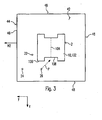
- the lighting component in a - sketch-like in Fig. 3 Projection along the first direction x viewed in a central region of the first planar light emitting surface 42 arranged.
- a corresponding arrangement of the lighting component or of the operating device 8 in the central region is at unimpeded light output to the sides y, z, and y - z particularly advantageous when - in Fig. 2
- the extension h of the lateral light emission areas 44, 48 in the first direction x is greater than the extension H of the luminaire in this direction, minus the corresponding extent b of the luminaire component or of the operating device 8.
- the luminaire component can also be formed by a reflector element 10.
- the reflector element 10 advantageously has a reflective surface 102.
- a region which is given by projection of the luminaire component or the reflector element 10 along the first direction x onto the first plane light emission surface 42 can be particularly illuminated.
- the effectiveness of the luminaire can be improved by the said reflection effect.
- the light fixture 8, 10 it would of course also be possible with respect to the first direction x "on" the light fixture 8, 10 to provide a further LED for emitting light via the first plane light emitting surface 42.
- this is particularly problematic in the case in which the lamp has a comparatively low height H , or more precisely formulated, if the extension b of the lamp component 8, 10 compared to the height H of the lamp is comparatively large, because this would be due to great proximity of this hypothetical LED to the first plan Light emitting surface 42 lead to a punctual brightening on this light emitting surface 42 and thus again oppose a homogeneous light output.
- the LED 2 is advantageously arranged in the projection mentioned within the first planar light emitting surface 42 but outside the reflector element 10 or at least outside the reflective surface 102.
- the LED 2 can be arranged in this sense immediately "next to" the reflective surface 102.
- the said advantageous effect can also be achieved if the LED is arranged at a certain distance from the reflector element 10 or the reflecting surface 102; this is in Fig. 3 outlined with reference to an exemplary LED 22 shown.
- the reflector element 10 or the reflective surface 102 is roof-shaped, pyramid-shaped or conical.
- the reflector element 10 advantageously extends from the retaining element 6 in the direction of the first planar light-emitting surface 42.
- the holding element 6 may have a planar holding surface 62, preferably aligned parallel to the yz plane or the first planar light emitting surface 42, wherein the LED 2 and / or the reflector element 10 are arranged on the holding surface 62.
- the said advantage of the reflector element 10 can of course be achieved independently of the above-mentioned embodiment of the drop shadow S in the edge region 46.
- both features mentioned are provided in the example shown, so that can be realized in this way with good lighting efficiency, a particularly homogeneous light output.
- a total of several LEDs can of course be provided as the light source of the luminaire, with the totality of the LEDs providing the most homogeneous possible light output via the first planar light emitting surface 42 and also via the second and the further, ie the "lateral" light output surfaces 44, 48 should be achieved.
- a further LED 24 may be provided in a corner region of the mounting surface 62 for illuminating a corner region.
- a further LED 26 may be provided, which is arranged at a location in extension of the reflector element 10 along the gable region 104 on the support surface 62.
- the gable region 104 is oriented along the direction z
- the further LED 26 is arranged at a location in the direction z viewed from the reflector element 10.
- roof-shaped reflector element 10 viewed along the first direction x would be rectangular shaped, it could happen that - as indicated by the dotted arrow P - a radiated light from the other LED 26 by interaction with the pointing in the direction z edge 106 of Reflector element 10 causes an undesirable quasi "triangular" drop shadow on the first planar light emitting surface 42. It is therefore advantageous to provide a cutout or a cutout region 108 around the two-sided end regions of the gable region 104.
- a further homogenization of the light output can be achieved if the mounting surface 62 has a recess, in particular in the form of a passage opening, wherein the operating device 8 is arranged so as to cross over this recess in the first direction x .
- the operating device 8 can accordingly be arranged "sunk" in part in the support surface 62, so that a negative influence on a homogeneous light emission of the luminaire by the operating device 8 has already been reduced in this respect.
- Fig. 4a by way of example shows a sectional view normal to the first direction x, with a corresponding recess 64 in the form of a through-opening
- Fig. 4b an embodiment with an alternative form of the passage opening 64th
Landscapes
- Engineering & Computer Science (AREA)
- General Engineering & Computer Science (AREA)
- Power Engineering (AREA)
- Non-Portable Lighting Devices Or Systems Thereof (AREA)
Description
- Die Erfindung betrifft eine Leuchte mit einer LED (LED: lichtemittierende Diode) und mit einer lichtdurchlässigen Abdeckung, die eine erste plane Lichtabgabefläche mit einer ersten Flächennormalen aufweist, die in eine erste Richtung weist sowie eine zweite plane Lichtabgabefläche mit einer zweiten Flächennormalen, die in eine zweite Richtung weist, die sich von der ersten Richtung unterscheidet, wobei die erste plane Lichtabgabefläche von der zweiten planen Lichtabgabefläche lediglich durch einen Kantenbereich getrennt ist.
- Bei einer derartigen Leuchte kann es dazu kommen, dass das von der Leuchte auf der ersten oder zweiten planen Lichtabgabefläche erzeugte Licht inhomogen erscheint. In der Regel ist jedoch erwünscht, dass die Lichtabgabeflächen möglichst homogen erhellt erscheinen.
- Aus der
WO 2010/117734 A2 ist gemäß dem Oberbegriff des Anspruchs 1 eine LED-Leuchte mit mehreren Lichtabgabeflächen bekannt. Die Lichtabgabeflächen sind durch ein Rahmenteil aus Aluminium voneinander getrennt. - Der Erfindung liegt die Aufgabe zugrunde, eine entsprechende verbesserte Leuchte anzugeben; insbesondere soll die Leuchte - bei guter Effizienz - eine besonders homogen bzw. gleichmäßig aufgehellte Lichtabgabefläche zeigen können.
- Diese Aufgabe wird gemäß der Erfindung mit den in den unabhängigen Ansprüchen genannten Gegenständen gelöst. Besondere Ausführungsarten der Erfindung sind in den abhängigen Ansprüchen angegeben.
- Gemäß der Erfindung ist eine Leuchte vorgesehen, die eine LED aufweist und eine lichtdurchlässige Abdeckung, die eine erste plane Lichtabgabefläche mit einer ersten Flächennormalen aufweist, die in eine erste Richtung weist sowie eine zweite plane Lichtabgabefläche mit einer zweiten Flächennormalen, die in eine zweite Richtung weist, die sich von der ersten Richtung unterscheidet; dabei ist die erste plane Lichtabgabefläche von der zweiten planen Lichtabgabefläche lediglich durch einen Kantenbereich getrennt, wobei der Kantenbereich als Teil der Abdeckung ausgebildet ist und die Abdeckung aus lediglich einem Material besteht. Dabei ist die Leuchte derart gestaltet, dass ein von der LED abgestrahltes Licht die Leuchte zumindest teilweise über die erste plane Lichtabgabefläche verlässt. Weiterhin ist die Leuchte derart gestaltet, dass das von der LED abgestrahlte Licht einen Schlagschatten hervorruft, der zumindest teilweise innerhalb des Kantenbereichs verläuft.
- Dadurch, dass der Schlagschatten innerhalb des Kantenbereichs verläuft, lässt sich vermeiden, dass er auf der ersten planen Lichtabgabefläche erscheint. Hierdurch lässt sich erzielen, dass die erste plane Lichtabgabefläche besonders homogen erscheint. Außerdem lässt sich auf diese Weise auch vermeiden dass der Schlagschatten auf der zweiten planen Lichtabgabefläche erscheint, wodurch eine besonders homogen erhellte zweite Lichtabgabefläche ermöglicht ist.
- Vorzugsweise weist die Leuchte außerdem ein Halteelement auf, beispielsweise in Form eines Gehäuses der Leuchte, wobei sowohl die Abdeckung als auch die LED jeweils unmittelbar oder mittelbar lagefest an dem Halteelement angeordnet sind. Hierdurch ist ein vergleichsweise einfacher Aufbau der Leuchte ermöglicht.
- Vorteilhaft weist die Leuchte außerdem weitere Lichtabgabeflächen auf, wobei die zweite Lichtabgabefläche und die weiteren Lichtabgabeflächen derart angeordnet sind, dass sie die erste plane Lichtabgabefläche allseits umgeben, und zwar insbesondere unmittelbar bzw. lediglich über Kanten bzw. Kantenbereiche voneinander getrennt. Hierdurch ist ermöglicht, dass die Leuchte über Lichtabgabeflächen Licht sowohl in die erste Richtung abgibt, als auch nach allen Seiten um die erste Richtung herum.
- Weiterhin weist die Leuchte ein Leuchtenbauteil auf, das derart angeordnet ist, dass der Schlagschatten durch eine Wechselwirkung des von der LED abgestrahlten Lichts mit dem Leuchtenbauteil hervorgerufen ist. Insbesondere kann die Leuchte dabei derart gestaltet sein, dass das Leuchtenbauteil ein Betriebsgerät zum Betrieb der LED bildet oder ein solches zumindest teilweise überdacht. Auf diese Weise lässt sich eine negative Auswirkung des Leuchtenbauteils auf die Homogenität der Lichtabgabe besonders effektiv verringern. Dies ist insbesondere der Fall, wenn die Bauhöhe der Leuchte längs der ersten Richtung vergleichsweise klein ist.
- Vorteilhaft ist dabei das Leuchtenbauteil durch ein vorzugsweise dach-, pyramiden- oder kegelförmiges Reflektorelement gebildet. Hierdurch lässt sich eine - mit Bezug auf die erste Richtung in Verlängerung des Leuchtenbauteils gelegene, verdunkelte Stelle auf der ersten Lichtabgabefläche verringern - also relativ aufhellen - oder sogar praktisch verhindern.
- Vorzugsweise ist das Leuchtenbauteil in einer Projektion längs der ersten Richtung betrachtet in einem mittleren Bereich der ersten planen Lichtabgabefläche angeordnet. Hierdurch ist ermöglicht, dass das von der LED abgestrahlte Licht durch eine der weiteren Lichtabgabeflächen ungehindert austreten und die Leuchte verlassen kann.
- Gemäß einem weiteren Aspekt der Erfindung ist eine Leuchte vorgesehen, die eine LED aufweist und eine lichtdurchlässige Abdeckung, die eine erste plane Lichtabgabefläche mit einer ersten Flächennormalen aufweist, die in eine erste Richtung weist sowie eine zweite plane Lichtabgabefläche mit einer zweiten Flächennormalen, die in eine zweite Richtung weist, die sich von der ersten Richtung unterscheidet; dabei ist die erste plane Lichtabgabefläche von der zweiten planen Lichtabgabefläche lediglich durch einen Kantenbereich getrennt, wobei die Leuchte derart gestaltet ist, dass ein von der LED abgestrahltes Licht die Leuchte zumindest teilweise über die erste plane Lichtabgabefläche verlässt. Insbesondere kann es sich dabei auch um eine erfindungsgemäße Leuchte mit den oben genannten Merkmalen handeln. Weiterhin weist die Leuchte ein Reflektorelement mit einer reflektierenden Fläche auf, die das von der LED abgestrahlte Licht zumindest teilweise auf die erste plane Lichtabgabefläche lenkt.
- Durch die reflektierende Fläche lässt sich erzielen, dass ein Teil des von der LED abgestrahlten Lichts durch Reflexion an der reflektierenden Fläche in Richtung auf die erste plane Lichtabgabefläche gelenkt wird; auf diese Weise wird ein Bereich auf der ersten planen Lichtabgabefläche mit Licht versorgt, der andernfalls weniger Licht erhalten würde und damit als dunkler Fleck bzw. "Darkspot" auf der ersten planen Lichtabgabefläche erscheinen würde. Das Reflektorelement kann wie oben beschrieben ausgebildet sein. Insbesondere weist die Leuchte vorzugsweise weiterhin ein Betriebsgerät zum Betrieb der LED auf, wobei, in einer Projektion längs der ersten Richtung betrachtet, die reflektierende Fläche das Betriebsgerät umfassend und dabei in einem mittleren Bereich der ersten planen Lichtabgabefläche angeordnet ist. Vorteilhaft ist die reflektierende Fläche dachförmig, pyramidenförmig oder kegelförmig. Im Fall einer Dachform weist das Reflektorelement bzw. die reflektierende Fläche vorzugsweise an den durch die Dachform gebildeten Giebelenden ausgeschnittene Bereiche auf. Auf diese Weise lässt sich vermeiden, dass sich ein unerwünschter Schlagschatten auf der ersten planen Lichtabgabefläche durch Wechselwirkung von Licht einer weiteren LED mit einem der Giebelenden bildet.
- Das Halteelement weist vorteilhaft eine plane Halterungsfläche auf, auf der die LED angeordnet ist, wobei die Halterungsfläche eine Ausnehmung, insbesondere eine Durchtrittsöffnung aufweist, wobei ein Betriebsgerät zum Betrieb der LED die Ausnehmung durchgreifend angeordnet ist. Dabei ist die plane Halterungsfläche vorteilhaft parallel zu der ersten Lichtabgabefläche orientiert angeordnet. Auf diese Weise ist das Betriebsgerät "versenkt" angeordnet und bildet somit eine verringerte Beeinträchtigung einer homogenen Lichtabgabe.
- Gemäß einem noch weiteren Aspekt der Erfindung ist eine Leuchte vorgesehen, die eine LED aufweist und eine lichtdurchlässige Abdeckung, die eine erste plane Lichtabgabefläche mit einer ersten Flächennormalen aufweist, die in eine erste Richtung weist sowie eine zweite plane Lichtabgabefläche mit einer zweiten Flächennormalen, die in eine zweite Richtung weist, die sich von der ersten Richtung unterscheidet; dabei ist die erste plane Lichtabgabefläche von der zweiten planen Lichtabgabefläche lediglich durch einen Kantenbereich getrennt, wobei die Leuchte derart gestaltet ist, dass ein von der LED abgestrahltes Licht die Leuchte zumindest teilweise über die erste plane Lichtabgabefläche verlässt. Insbesondere kann es sich dabei auch um eine erfindungsgemäße Leuchte mit den oben genannten Merkmalen handeln. Weiterhin weist die Leuchte ein Halteelement mit einer planen Halterungsfläche auf, auf der die LED angeordnet ist, wobei die Halterungsfläche eine Ausnehmung, insbesondere eine Durchtrittsöffnung aufweist, wobei ein Betriebsgerät zum Betrieb der LED die Ausnehmung durchgreifend angeordnet ist.
- Die Erfindung wird im Folgenden anhand von Ausführungsbeispielen und mit Bezug auf die Zeichnungen näher erläuter. Es zeigen:
- Fig. 1
- eine perspektivische Ansicht eines Ausführungsbeispiels einer erfindungsgemäßen Leuchte,
- Fig. 2
- eine schematische Querschnittskizze hierzu,
- Fig. 3
- eine Skizze einer Projektion der Leuchte längs der ersten Richtung und
- Figuren 4a und 4b
- Schnittdarstellungen zu Variationen mit einem "versenkten" Betriebsgerät.
-
Fig. 1 zeigt eine perspektivische Ansicht eines Ausführungsbeispiels einer erfindungsgemäßen Leuchte. Bei der Leuchte kann es sich insbesondere um eine Anbauleuchte handeln, beispielsweise um eine Decken- oder Wandanbauleuchte. - Zur leichteren Beschreibung ist ein kartesisches Koordinatensystem mit den Achsen bzw. den dadurch festgelegten Richtungen x, y und z gewählt und in
Fig. 1 angedeutet. Die Leuchte weist eine lichtdurchlässige, insbesondere opale Abdeckung 4 auf, die eine erste plane Lichtabgabefläche 42 aufweist. Die erste plane Lichtabgabefläche 42 weist eine erste Flächennormale N1 auf, die in eine erste Richtung, im gezeigten Beispiel in die Richtung x, weist. Weiterhin weist die Abdeckung 4 eine zweite plane Lichtabgabefläche 44 mit einer zweiten Flächennormalen N2 auf, die in eine zweite Richtung weist, hier in die Richtung y. Wie im Beispiel der Fall, kann dabei vorzugsweise die zweite Flächennormale N2 mit der ersten Flächennormalen N1 einen rechten Winkel einschließen. - Außerdem kann die Leuchte noch weitere, vorzugsweise ebenfalls jeweils plane Lichtabgabeflächen 48, im gezeigten Beispiel drei weitere Lichtabgabeflächen 48 aufweisen, wobei die weiteren Lichtabgabeflächen 48 und die zweite Lichtabgabefläche 44 derart angeordnet sind, dass sie die erste plane Lichtabgabefläche 42 allseits umgeben. Wie gezeigt, können die weiteren Lichtabgabeflächen 48 jeweils plan sein und in die Richtungen z, -y und -z weisen. Die erste plane Lichtabgabefläche 42 kann rechteckig, beispielsweise quadratisch sein und sie kann die größte der genannten Lichtabgabeflächen 42, 44, 48 darstellen, so dass die Lichtabgabe der Leuchte in die erste Richtung x als Hauptlichtabgaberichtung bezeichnet werden kann.
- Die erste plane Lichtabgabefläche 42 ist von der zweiten planen Lichtabgabefläche 44 lediglich durch einen Kantenbereich 46 getrennt. Der Kantenbereich 46 kann insbesondere ein geradlinig verlaufender Kantenbereich 46 sein. Die zweite plane Lichtabgabefläche 44 und die weiteren Lichtabgabeflächen 48 können die erste plane Lichtabgabefläche 42 lediglich über analog gebildete, weitere Kantenbereiche 50 bzw. Kanten voneinander getrennt umgeben. Sowohl der Kantenbereich 46 als auch die weiteren Kantenbereiche 50 sind ebenfalls als Teil der Abdeckung 4 ausgebildet. Dabei besteht die Abdeckung 4 aus lediglich einem Material.
- Weiterhin kann die Leuchte ein Halteelement 6 aufweisen, bei dem es sich beispielsweise um ein Gehäuse oder eine Gehäusewanne der Leuchte handeln kann. Das Halteelement 6 kann zur unmittelbaren oder auch mittelbaren lagefesten Halterung der Abdeckung 4 ausgestaltet sein.
-
Fig. 2 zeigt in schematischer Form eine Schnittdarstellung der Leuchte normal zur z-Achse bzw. in einer durch die erste Flächennormale N1 und die zweite Flächennormale N2 festgelegten Ebene. Man erkennt die Abdeckung 4 mit der ersten planen Lichtabgabefläche 42, der zweiten planen Lichtabgabefläche 44 und an der Verbindungsstelle dieser beiden Flächen den genannten Kantenbereich 46. Weiterhin erkannt man das Halteelement 6. - Wie in
Fig. 2 beispielhaft gezeigt, weist die Leuchte außerdem eine LED 2 auf, wobei die Gestaltung derart ist, dass ein von der LED 2 abgestrahltes Licht die Leuchte zumindest teilweise über die erste plane Lichtabgabefläche 42 verlässt. Die Leuchte weist vorteilhaft noch wenigstens eine weitere LED 2' auf, wobei ein von dieser wenigstens einen weiteren LED 2' abgestrahltes Licht die Leuchte ebenfalls zumindest teilweise über die erste plane Lichtabgabefläche 42 verlässt. Die Leuchte ist mit Bezug auf die wenigstens eine weitere LED 2' vorzugsweise genauso bzw. analog ausgebildet wie mit Bezug auf die eine zuerst genannte LED 2. - Vorteilhaft ist die LED 2 unmittelbar oder mittelbar lagefest mit dem Halteelement 6 verbunden. Insbesondere kann dementsprechend durch das Halteelement 6 eine fixe Relativpositionierung zwischen der LED 2 und der Abdeckung 4 gewährleistet sein.
- Wie weiterhin schematisch in
Fig. 2 skizziert, ist die Leuchte derart gestaltet, dass das von der LED 2 abgestrahlte Licht einen Schlagschatten S hervorruft, der zumindest teilweise, im gezeigten Beispiel längs der z-Achse, innerhalb des Kantenbereichs 46 verläuft. - Der Schlagschatten S kann insbesondere durch Wechselwirkung des von der LED 2 abgestrahlten Lichts mit einem Leuchtenbauteil hervorgerufen sein. Bei dem Leuchtenbauteil kann es sich insbesondere um ein Betriebsgerät 8 zum Betrieb der LED 2 handeln, beispielsweise um einen entsprechenden Konverter. Das Betriebsgerät 8 kann beispielsweise eine längliche Kante 82 aufweisen, durch deren Abbildung der Schlagschatten S gebildet ist.
- Wie weiterhin in
Fig. 2 zur Verdeutlichung skizziert, würde der Schlagschatten S nicht innerhalb des Kantenbereichs 46 verlaufen, wenn die LED 2 an einer gewissen anderen Position L1 an dem Halteelement 6 angeordnet wäre. In dem beispielhaft gezeigten Fall entstünde der Schlagschatten hierbei längs einer Linie S1, die sich abseits des Kantenbereichs 46 in einem mittleren Bereich der ersten planen Lichtabgabefläche 42 befindet; auf diese Weise würde eine Inhomogenität der Lichtabgabe über die erste plane Lichtabgabefläche 42 hervorgerufen werden. Dadurch, dass die Gestaltung jedoch erfindungsgemäß derart gewählt ist, dass der Schlagschatten S längs bzw. innerhalb des Kantenbereichs 46 verläuft, lässt sich diese mögliche Inhomogenität vermeiden und somit eine besonders homogene Lichtabgabe über die erste plane Lichtabgabefläche 42 erzielen. - Dementsprechend ist die Anordnung vorteilhaft derart, dass im gezeigten Schnitt betrachtet die Kante 82 des Leuchtenbauteils sowohl mit dem Kantenbereich 46 als auch mit der LED 2 auf einer Geraden G liegt.
- Eine derartige Ausgestaltung ist insbesondere von Vorteil, wenn die Leuchte nicht nur in die erste Richtung x Licht abgibt, sondern auch in die hierzu allseits seitlich verlaufenden Richtungen y, z, -y und -z, denn in diesem Fall muss das Betriebsgerät 8 in einem mittleren Bereich angeordnet werden, um eine gute Lichtabgabe zu den Seiten hin zu ermöglichen. In diesem Sinne ist weiterhin vorteilhaft das Leuchtenbauteil in einer - skizzenartig in
Fig. 3 gezeigten - Projektion längs der ersten Richtung x betrachtet in einem mittleren Bereich der ersten planen Lichtabgabefläche 42 angeordnet. - Eine entsprechende Anordnung des Leuchtenbauteils bzw. des Betriebsgeräts 8 in dem mittleren Bereich ist zur ungehinderten Lichtabgabe zu den Seiten y, z, -y und -z besonders vorteilhaft, wenn eine - in
Fig. 2 beispielhaft bezeichnete - Erstreckung h der seitlichen Lichtabstrahlflächen 44, 48 in der ersten Richtung x größer ist als die Erstreckung H der Leuchte in dieser Richtung abzüglich der entsprechenden Erstreckung b des Leuchtenbauteils bzw. des Betriebsgeräts 8. - Vorteilhaft kann das Leuchtenbauteil auch durch ein Reflektorelement 10 gebildet sein. Hierdurch lässt sich erzielen, dass durch das Reflektorelement 10 Licht, das beispielsweise von der LED 2 stammt oder Streulicht, in Richtung auf die erste plane Lichtabgabefläche 42 gelenkt wird. Hierzu weist das Reflektorelement 10 vorteilhaft eine reflektierende Fläche 102 auf. Auf diese Weise lässt sich ein Bereich, der durch Projektion des Leuchtenbauteils bzw. des Reflektorelements 10 längs der ersten Richtung x auf die erste plane Lichtabgabefläche 42 gegeben ist, besonders erhellen. Auf diese Weise lässt sich die Wahrscheinlichkeit verringern, dass in diesem Projektionsbereich auf der ersten planen Lichtabgabefläche 42 eine deutlich dunklere Stelle, ein "Darkspot" entsteht bzw. erkennbar wird. Auch die Effektivität der Leuchte lässt sich durch die genannte Reflexionswirkung verbessern.
- Grundsätzlich ließe sich natürlich auch mit Bezug auf die erste Richtung x "auf" dem Leuchtanbauteil 8, 10 eine weitere LED zur Lichtabgabe über die erste plane Lichtabgabefläche 42 vorsehen. Dies ist allerdings besonders in dem Fall problematisch, in dem die Leuchte eine vergleichsweise niedrige Bauhöhe H aufweist, bzw. präziser formuliert, wenn die Erstreckung b des Leuchtenbauteils 8, 10 im Vergleich zur Bauhöhe H der Leuchte vergleichsweise groß ist, denn dies würde aufgrund der großen Nähe dieser hypothetischen LED zu der ersten planen Lichtabgabefläche 42 zu einer punktuellen Aufhellung auf dieser Lichtabgabefläche 42 führen und somit wiederum einer homogenen Lichtabgabe entgegenstehen.
- Dementsprechend ist die LED 2 vorteilhaft in der genannten Projektion betrachtet zwar innerhalb der ersten planen Lichtabgabefläche 42, aber außerhalb des Reflektorelements 10 oder zumindest außerhalb der reflektierenden Fläche 102 angeordnet. Wie in den
Figuren 2 und3 skizzenartig angedeutet, kann die LED 2 in diesem Sinne unmittelbar "neben" der reflektierenden Fläche 102 angeordnet sein. Der genannte vorteilhafte Effekt lässt sich jedoch auch erzielen, wenn die LED in einem gewissen Abstand von dem Reflektorelement 10 bzw. der reflektierenden Fläche 102 angeordnet ist; dies ist inFig. 3 anhand einer exemplarisch gezeigten weiteren LED 22 skizziert. - Vorzugsweise ist das Reflektorelement 10 bzw. die reflektierende Fläche 102 dachförmig, pyramidenförmig oder kegelförmig. Vorteilhaft erstreckt sich dabei das Reflektorelement 10 von dem Halteelement 6 aus in Richtung auf die erste plane Lichtabgabefläche 42 zu. Beispielsweise kann das Halteelement 6 eine plane Halterungsfläche 62 aufweisen, vorzugsweise parallel zu der yz-Ebene bzw. der ersten planen Lichtabgabefläche 42 ausgerichtet, wobei die LED 2 und/oder das Reflektorelement 10 an der Haltefläche 62 angeordnet sind.
- Bei dem in den
Figuren 2 und3 beispielhaft gezeigten Fall ist die reflektierende Fläche 102 dachförmig und weist einen Giebelbereich 104 auf, der in Richtung auf die erste plane Lichtabgabefläche 42 weist. Mit ihrer - mit Bezug auf die Zeichnung - rechten Hälfte ist die reflektierende Fläche 102 gegenüber der yz-Ebene um den Winkel w2 = = 15° geneigt. Wenn nun die LED 2 einen Halbwertwinkel α = 120° (symmetrisch um die erste Richtung x) aufweist, gelangt zum einen ein Anteil des von der LED 2 außerhalb des Halbwertwinkels α abgestrahlten Lichts auf die reflektierende Fläche 102, zum anderen allgemeines Streulicht und das so an der reflektierenden Fläche 102 reflektierte Licht wird durch die Reflexion zumindest teilweise auf die erste plane Lichtabgabefläche 42 gelenkt. - Würde sich die LED - wie weiter oben beschrieben - an der Stelle L1 befinden, so wäre durch das Licht dieser hypothetischen LED, das den Schlagschatten S1 hervorrufen würde, ein Winkel w1 = 30° mit der yz-Ebene eingeschlossen.
- Im gezeigten Beispiel ist - mit Bezug auf die Schnittdarstellung der
Fig. 2 - die rechte Hälfte der reflektierenden Fläche 102 plan und dabei derart geneigt, dass sie längs der Geraden G verläuft. Auf diese Weise kann bei vergleichsweise geringer Gesamterstreckung des Reflektorelements 10 längs der Richtung y Licht von der LED 2 bis in den Kantenbereich 46 gelangen. - Der genannte Vorteil des Reflektorelements 10 lässt sich natürlich an sich unabhängig von der weiter oben erwähnten Ausbildung des Schlagschattens S im Kantenbereich 46 erzielen. Allerdings sind im gezeigten Beispiel beide genannten Merkmale vorgesehen, so dass sich auf diese Weise bei guter lichttechnischer Effizienz eine besonders homogene Lichtabgabe verwirklichen lässt.
- Wie bereits erwähnt, können natürlich insgesamt mehrere LEDs als Lichtquelle der Leuchte vorgesehen sein, wobei durch die Gesamtheit der LEDs eine möglichst homogene Lichtabgabe über die erste plane Lichtabgabefläche 42 und auch über die zweite und die weiteren, also die "seitlichen" Lichtabgabeflächen 44, 48 erzielt werden soll. Wie in
Fig. 3 exemplarisch gezeigt, kann zur Ausleuchtung eines Eckenbereichs beispielsweise eine weitere LED 24 in einem Eckenbereich der Halterungsfläche 62 vorgesehen sein. Im Fall eines dachförmigen Reflektorelements 10 kann eine weitere LED 26 vorgesehen sein, die an einer Stelle in Verlängerung des Reflektorelements 10 längs des Giebelbereichs 104 an der Halterungsfläche 62 angeordnet ist. Im gezeigten Beispiel ist der Giebelbereich 104 längs der Richtung z orientiert und die weitere LED 26 ist vom Reflektorelement 10 aus betrachtet an einer Stelle in der Richtung z angeordnet. - Die in
Fig. 3 skizzierte Platzierung der weiteren LEDs 22, 24, 26 eignet sich zur homogenen Ausleuchtung des - mit Bezug auf die Zeichnung - linken unteren Viertels der Leuchte bzw. Abdeckung. Zur homogenen Lichtabgabe über alle Lichtabgabeflächen kann diese Anordnung bzw. Platzierung analog in den anderen drei Vierteln vorgesehen sein. - Falls das dachförmige Reflektorelement 10 längs der ersten Richtung x betrachtet rechteckig geformt wäre, könnte es dazu kommen, dass - wie durch den punktierten Pfeil P angedeutet - ein von der weiteren LED 26 abgestrahltes Licht durch Wechselwirkung mit der in die Richtung z weisenden Kante 106 des Reflektorelements 10 einen unerwünschten quasi "dreieckigen" Schlagschatten auf der ersten planen Lichtabgabefläche 42 hervorruft. Daher ist es vorteilhaft, um die beidseitigen Endbereiche des Giebelbereichs 104 herum jeweils einen Ausschnitt bzw. einen ausgeschnittenen Bereich 108 vorzusehen.
- Eine weitergehende Homogenisierung der Lichtabgabe lässt sich erzielen, wenn die Halterungsfläche 62 eine Ausnehmung, insbesondere in Form einer Durchtrittsöffnung aufweist, wobei das Betriebsgerät 8 diese Ausnehmung in die erste Richtung x betrachtet durchgreifend angeordnet ist. Das Betriebsgerät 8 lässt sich dementsprechend in der Halterungsfläche 62 zum Teil "versenkt" anordnen, so dass ein negativer Einfluss auf eine homogene Lichtabgabe der Leuchte durch das Betriebsgerät 8 insoweit bereits reduziert ist.
-
Fig. 4a zeigt beispielhaft eine Schnittdarstellung normal zur ersten Richtung x, mit einer entsprechenden Ausnehmung 64 in Form einer Durchtrittsöffnung,Fig. 4b eine Ausführung mit einer alternativen Form der Durchtrittsöffnung 64. - Der genannte Vorteil der versenkten Anordnung des Betriebsgeräts 8 lässt sich natürlich unabhängig von den weiter oben erwähnten Ausbildungen des Schlagschattens S und des Reflektorelements 10 erzielen. Allerdings können zwei der drei oder auch alle drei genannten Merkmale vorgesehen sein, so dass sich auf diese Weise wiederum eine besonders homogene Lichtabgabe verwirklichen lässt.
Claims (12)
- Leuchte, aufweisend- eine LED (2),- eine lichtdurchlässige Abdeckung (4), die eine erste plane Lichtabgabefläche (42) mit einer ersten Flächennormalen (N1) aufweist, die in eine erste Richtung (x) weist sowie eine zweite plane Lichtabgabefläche (44) mit einer zweiten Flächennormalen (N2), die in eine zweite Richtung (y) weist, die sich von der ersten Richtung (x) unterscheidet, wobei die erste plane Lichtabgabefläche (42) von der zweiten planen Lichtabgabefläche (44) lediglich durch einen Kantenbereich (46) getrennt ist,wobei die Leuchte derart gestaltet ist, dass ein von der LED (2) abgestrahltes Licht die Leuchte zumindest teilweise über die erste plane Lichtabgabefläche (42) verlässt,
dadurch gekennzeichnet,
dass der Kantenbereich (46) als Teil der Abdeckung (4) ausgebildet ist und die Abdeckung (4) aus lediglich einem Material besteht, die Leuchte außerdem derart gestaltet ist, dass das von der LED (2) abgestrahlte Licht einen Schlagschatten (S) durch Wechselwirkung mit einem Leuchtenbauteil hervorruft, der zumindest teilweise innerhalb des Kantenbereichs (46) verläuft. - Leuchte nach Anspruch 1,
weiterhin aufweisend- ein Halteelement (6), beispielsweise in Form eines Gehäuses der Leuchte, wobei sowohl die Abdeckung (4) als auch die LED (2) jeweils unmittelbar oder mittelbar lagefest an dem Halteelement (6) angeordnet sind. - Leuchte nach Anspruch 1 oder 2,
weiterhin aufweisend- weitere Lichtabgabeflächen (48), wobei die zweite plane Lichtabgabefläche (44) und die weiteren Lichtabgabeflächen (48) derart angeordnet sind, dass sie die erste plane Lichtabgabefläche (42) allseits, insbesondere unmittelbar bzw. lediglich durch Kantenbereiche voneinander getrennt umgeben. - Leuchte nach einem der vorhergehenden Ansprüche,
weiterhin aufweisend- ein Leuchtenbauteil (8, 10), das derart angeordnet ist, dass der Schlagschatten (S) durch eine Wechselwirkung des von der LED (2) abgestrahlten Lichts mit dem Leuchtenbauteil (8, 10) hervorgerufen ist. - Leuchte nach Anspruch 4,
die derart gestaltet ist, dass das Leuchtenbauteil (8, 10) ein Betriebsgerät (8) zum Betrieb der LED (2) bildet oder ein solches zumindest teilweise überdacht. - Leuchte nach Anspruch 4 oder 5,
bei der das Leuchtenbauteil durch ein vorzugsweise dach-, pyramiden- oder kegelförmiges Reflektorelement (10) gebildet ist. - Leuchte nach einem der Ansprüche 4 bis 6,
bei der das Leuchtenbauteil (8, 10) in einer Projektion längs der ersten Richtung (x) betrachtet in einem mittleren Bereich der ersten planen Lichtabgabefläche (42) angeordnet ist. - Leuchte nach Anspruch 6,
bei der das Reflektorelement (10) eine reflektierende Fläche (102) aufweist, die das von der LED (2) abgestrahlte Licht zumindest teilweise auf die erste plane Lichtabgabefläche (42) lenkt. - Leuchte nach Anspruch 8,
weiterhin aufweisend- ein Betriebsgerät (8) zum Betrieb der LED,wobei, in einer Projektion längs der ersten Richtung (x) betrachtet, die reflektierende Fläche (102) das Betriebsgerät (8) umfassend und dabei in einem mittleren Bereich der ersten planen Lichtabgabefläche (42) angeordnet ist. - Leuchte nach Anspruch 8 oder 9,
bei der die reflektierende Fläche (102) dachförmig, pyramidenförmig oder kegelförmig ist und im Fall einer Dachform vorzugsweise an den durch die Dachform gebildeten Giebelenden ausgeschnittene Bereiche (108) aufweist. - Leuchte nach Anspruch 2 oder einem von Anspruch 2 abhängigen Anspruch,
bei der das Halteelement (6) eine plane Halterungsfläche (62) aufweist, auf der die LED (2) angeordnet ist, wobei die Halterungsfläche (62) eine Ausnehmung (64), insbesondere eine Durchtrittsöffnung aufweist, wobei ein Betriebsgerät (8) zum Betrieb der LED (2) die Ausnehmung (64) durchgreifend angeordnet ist. - Leuchte nach Anspruch 11,
bei der die plane Halterungsfläche (62) parallel zu der ersten Lichtabgabefläche (42) orientiert angeordnet ist.
Applications Claiming Priority (1)
| Application Number | Priority Date | Filing Date | Title |
|---|---|---|---|
| DE202011000997U DE202011000997U1 (de) | 2011-04-28 | 2011-04-28 | LED-Leuchte mit gleichmäßig erhellter Lichtabgabefläche |
Publications (3)
| Publication Number | Publication Date |
|---|---|
| EP2518394A2 EP2518394A2 (de) | 2012-10-31 |
| EP2518394A3 EP2518394A3 (de) | 2013-01-09 |
| EP2518394B1 true EP2518394B1 (de) | 2014-03-26 |
Family
ID=46049222
Family Applications (1)
| Application Number | Title | Priority Date | Filing Date |
|---|---|---|---|
| EP12165457.8A Not-in-force EP2518394B1 (de) | 2011-04-28 | 2012-04-25 | LED-Leuchte mit gleichmäßig erhellter Lichtabgabefläche |
Country Status (2)
| Country | Link |
|---|---|
| EP (1) | EP2518394B1 (de) |
| DE (1) | DE202011000997U1 (de) |
Family Cites Families (6)
| Publication number | Priority date | Publication date | Assignee | Title |
|---|---|---|---|---|
| US1668788A (en) * | 1926-06-09 | 1928-05-08 | Thomas Day Company | Chandelier |
| US4141061A (en) * | 1977-05-25 | 1979-02-20 | Ford Lloyd W | Vandal-resistant fluorescent fixture |
| GB2405461B (en) * | 2003-08-30 | 2006-01-11 | Pulsar Light Of Cambridge Ltd | Lighting panel |
| FR2882588B1 (fr) * | 2005-02-25 | 2007-04-27 | Normalu Sa | Caisson lumineux a raidisseur invisible |
| WO2010117734A2 (en) * | 2009-03-30 | 2010-10-14 | Hunter Douglas Industries B.V. | Light boxes with uniform light distribution |
| DE102009042338B4 (de) * | 2009-09-21 | 2019-03-21 | Berchtold Holding Gmbh | Operationsleuchte |
-
2011
- 2011-04-28 DE DE202011000997U patent/DE202011000997U1/de not_active Expired - Lifetime
-
2012
- 2012-04-25 EP EP12165457.8A patent/EP2518394B1/de not_active Not-in-force
Also Published As
| Publication number | Publication date |
|---|---|
| EP2518394A3 (de) | 2013-01-09 |
| DE202011000997U1 (de) | 2012-07-30 |
| EP2518394A2 (de) | 2012-10-31 |
Similar Documents
| Publication | Publication Date | Title |
|---|---|---|
| DE102017219953B4 (de) | Fahrzeugleuchte | |
| EP1519102A2 (de) | Reflektorleuchte, wie Boden-, Decken- oder Wandeinbau-Reflektorleuchte, insbesondere Stufen-Reflektorleuchte | |
| EP1979668A2 (de) | Leuchte mit einem kastenförmigen leuchtengehäuse und einem lichtaustrittselement | |
| EP2485073A2 (de) | Leuchte mit diffuser und gebündelter Lichtabgabe | |
| DE102010041478A1 (de) | Anordnung zur gerichteten Lichtabgabe | |
| EP2993394B1 (de) | Leuchte | |
| EP1843086B1 (de) | Reflektorleuchte | |
| DE10011378B4 (de) | Hohllichtleiterleuchte mit indirekter Lichtabstrahlung | |
| WO2015091480A1 (de) | Leuchtenanordnung sowie leuchte | |
| DE3030080C2 (de) | Langgestreckte Arbeitsplatzleuchte | |
| EP0638764B1 (de) | Vorwiegend direkt strahlende Innenleuchte | |
| EP3283820A1 (de) | Optisches system sowie anordnung zur lichtabgabe | |
| EP2989378B1 (de) | Led-leuchte mit unterschiedlich einstellbaren lichtverteilungen | |
| EP2518394A2 (de) | LED-Leuchte mit gleichmäßig erhellter Lichtabgabefläche | |
| EP2657083A2 (de) | Leuchte für die Innenbeleuchtung eines Fahrzeuges mit einem Hauptreflektor und einen Hilfsreflektor | |
| EP0984271A2 (de) | Beleuchtungsanlage zur Abmusterung von Oberflächenfehlern auf glänzenden Oberflächen, insbesondere lackierten Automobilkarosserien | |
| EP3767159B1 (de) | Notlichtleuchte | |
| EP3865761A1 (de) | Leuchte mit kombinierter shelfwasher- und spotfunktion | |
| EP0217323A2 (de) | Leuchte und Beleuchtungsverfahren | |
| EP3627042B1 (de) | Leuchte mit plattenförmigem lichtleitelement | |
| EP4168711B1 (de) | Anordnung zur lichtabgabe und leuchte | |
| AT17328U1 (de) | Flache LED-Leuchte | |
| EP1130311B1 (de) | Leuchte mit einer mehreckigen Lichtausstrittsfläche und einer geradlinigen Prismenstruktur | |
| EP1843082B1 (de) | Deckenleuchte, insbesondere zur Verwendung in einem Flur | |
| AT392527B (de) | Leuchte mit einer langgestreckten roehrenartigen leuchtstofflampe |
Legal Events
| Date | Code | Title | Description |
|---|---|---|---|
| PUAI | Public reference made under article 153(3) epc to a published international application that has entered the european phase |
Free format text: ORIGINAL CODE: 0009012 |
|
| AK | Designated contracting states |
Kind code of ref document: A2 Designated state(s): AL AT BE BG CH CY CZ DE DK EE ES FI FR GB GR HR HU IE IS IT LI LT LU LV MC MK MT NL NO PL PT RO RS SE SI SK SM TR |
|
| AX | Request for extension of the european patent |
Extension state: BA ME |
|
| PUAL | Search report despatched |
Free format text: ORIGINAL CODE: 0009013 |
|
| AK | Designated contracting states |
Kind code of ref document: A3 Designated state(s): AL AT BE BG CH CY CZ DE DK EE ES FI FR GB GR HR HU IE IS IT LI LT LU LV MC MK MT NL NO PL PT RO RS SE SI SK SM TR |
|
| AX | Request for extension of the european patent |
Extension state: BA ME |
|
| RIC1 | Information provided on ipc code assigned before grant |
Ipc: F21V 3/02 20060101AFI20121130BHEP Ipc: F21V 13/02 20060101ALI20121130BHEP Ipc: F21V 7/04 20060101ALI20121130BHEP Ipc: F21V 23/02 20060101ALI20121130BHEP Ipc: F21V 11/00 20060101ALI20121130BHEP |
|
| 17P | Request for examination filed |
Effective date: 20130621 |
|
| RBV | Designated contracting states (corrected) |
Designated state(s): AL AT BE BG CH CY CZ DE DK EE ES FI FR GB GR HR HU IE IS IT LI LT LU LV MC MK MT NL NO PL PT RO RS SE SI SK SM TR |
|
| REG | Reference to a national code |
Ref country code: DE Ref legal event code: R079 Ref document number: 502012000503 Country of ref document: DE Free format text: PREVIOUS MAIN CLASS: F21V0003020000 Ipc: F21V0011000000 |
|
| GRAP | Despatch of communication of intention to grant a patent |
Free format text: ORIGINAL CODE: EPIDOSNIGR1 |
|
| RIC1 | Information provided on ipc code assigned before grant |
Ipc: F21V 13/02 20060101ALI20130806BHEP Ipc: F21V 23/02 20060101ALI20130806BHEP Ipc: F21V 7/04 20060101ALI20130806BHEP Ipc: F21V 11/00 20060101AFI20130806BHEP Ipc: F21Y 101/02 20060101ALI20130806BHEP Ipc: F21V 3/02 20060101ALI20130806BHEP |
|
| INTG | Intention to grant announced |
Effective date: 20130910 |
|
| GRAP | Despatch of communication of intention to grant a patent |
Free format text: ORIGINAL CODE: EPIDOSNIGR1 |
|
| GRAS | Grant fee paid |
Free format text: ORIGINAL CODE: EPIDOSNIGR3 |
|
| GRAA | (expected) grant |
Free format text: ORIGINAL CODE: 0009210 |
|
| INTG | Intention to grant announced |
Effective date: 20140128 |
|
| AK | Designated contracting states |
Kind code of ref document: B1 Designated state(s): AL AT BE BG CH CY CZ DE DK EE ES FI FR GB GR HR HU IE IS IT LI LT LU LV MC MK MT NL NO PL PT RO RS SE SI SK SM TR |
|
| REG | Reference to a national code |
Ref country code: GB Ref legal event code: FG4D Free format text: NOT ENGLISH |
|
| REG | Reference to a national code |
Ref country code: CH Ref legal event code: EP |
|
| REG | Reference to a national code |
Ref country code: AT Ref legal event code: REF Ref document number: 659195 Country of ref document: AT Kind code of ref document: T Effective date: 20140415 |
|
| REG | Reference to a national code |
Ref country code: IE Ref legal event code: FG4D Free format text: LANGUAGE OF EP DOCUMENT: GERMAN |
|
| REG | Reference to a national code |
Ref country code: DE Ref legal event code: R096 Ref document number: 502012000503 Country of ref document: DE Effective date: 20140508 |
|
| REG | Reference to a national code |
Ref country code: CH Ref legal event code: NV Representative=s name: FIAMMENGHI-FIAMMENGHI, CH |
|
| PG25 | Lapsed in a contracting state [announced via postgrant information from national office to epo] |
Ref country code: LT Free format text: LAPSE BECAUSE OF FAILURE TO SUBMIT A TRANSLATION OF THE DESCRIPTION OR TO PAY THE FEE WITHIN THE PRESCRIBED TIME-LIMIT Effective date: 20140326 Ref country code: NO Free format text: LAPSE BECAUSE OF FAILURE TO SUBMIT A TRANSLATION OF THE DESCRIPTION OR TO PAY THE FEE WITHIN THE PRESCRIBED TIME-LIMIT Effective date: 20140626 |
|
| REG | Reference to a national code |
Ref country code: NL Ref legal event code: VDEP Effective date: 20140326 |
|
| REG | Reference to a national code |
Ref country code: LT Ref legal event code: MG4D |
|
| PG25 | Lapsed in a contracting state [announced via postgrant information from national office to epo] |
Ref country code: FI Free format text: LAPSE BECAUSE OF FAILURE TO SUBMIT A TRANSLATION OF THE DESCRIPTION OR TO PAY THE FEE WITHIN THE PRESCRIBED TIME-LIMIT Effective date: 20140326 Ref country code: SE Free format text: LAPSE BECAUSE OF FAILURE TO SUBMIT A TRANSLATION OF THE DESCRIPTION OR TO PAY THE FEE WITHIN THE PRESCRIBED TIME-LIMIT Effective date: 20140326 |
|
| PG25 | Lapsed in a contracting state [announced via postgrant information from national office to epo] |
Ref country code: HR Free format text: LAPSE BECAUSE OF FAILURE TO SUBMIT A TRANSLATION OF THE DESCRIPTION OR TO PAY THE FEE WITHIN THE PRESCRIBED TIME-LIMIT Effective date: 20140326 Ref country code: RS Free format text: LAPSE BECAUSE OF FAILURE TO SUBMIT A TRANSLATION OF THE DESCRIPTION OR TO PAY THE FEE WITHIN THE PRESCRIBED TIME-LIMIT Effective date: 20140326 Ref country code: LV Free format text: LAPSE BECAUSE OF FAILURE TO SUBMIT A TRANSLATION OF THE DESCRIPTION OR TO PAY THE FEE WITHIN THE PRESCRIBED TIME-LIMIT Effective date: 20140326 |
|
| PG25 | Lapsed in a contracting state [announced via postgrant information from national office to epo] |
Ref country code: CZ Free format text: LAPSE BECAUSE OF FAILURE TO SUBMIT A TRANSLATION OF THE DESCRIPTION OR TO PAY THE FEE WITHIN THE PRESCRIBED TIME-LIMIT Effective date: 20140326 Ref country code: BG Free format text: LAPSE BECAUSE OF FAILURE TO SUBMIT A TRANSLATION OF THE DESCRIPTION OR TO PAY THE FEE WITHIN THE PRESCRIBED TIME-LIMIT Effective date: 20140626 Ref country code: NL Free format text: LAPSE BECAUSE OF FAILURE TO SUBMIT A TRANSLATION OF THE DESCRIPTION OR TO PAY THE FEE WITHIN THE PRESCRIBED TIME-LIMIT Effective date: 20140326 Ref country code: EE Free format text: LAPSE BECAUSE OF FAILURE TO SUBMIT A TRANSLATION OF THE DESCRIPTION OR TO PAY THE FEE WITHIN THE PRESCRIBED TIME-LIMIT Effective date: 20140326 Ref country code: IS Free format text: LAPSE BECAUSE OF FAILURE TO SUBMIT A TRANSLATION OF THE DESCRIPTION OR TO PAY THE FEE WITHIN THE PRESCRIBED TIME-LIMIT Effective date: 20140726 Ref country code: RO Free format text: LAPSE BECAUSE OF FAILURE TO SUBMIT A TRANSLATION OF THE DESCRIPTION OR TO PAY THE FEE WITHIN THE PRESCRIBED TIME-LIMIT Effective date: 20140326 Ref country code: CY Free format text: LAPSE BECAUSE OF FAILURE TO SUBMIT A TRANSLATION OF THE DESCRIPTION OR TO PAY THE FEE WITHIN THE PRESCRIBED TIME-LIMIT Effective date: 20140326 |
|
| PG25 | Lapsed in a contracting state [announced via postgrant information from national office to epo] |
Ref country code: SK Free format text: LAPSE BECAUSE OF FAILURE TO SUBMIT A TRANSLATION OF THE DESCRIPTION OR TO PAY THE FEE WITHIN THE PRESCRIBED TIME-LIMIT Effective date: 20140326 Ref country code: ES Free format text: LAPSE BECAUSE OF FAILURE TO SUBMIT A TRANSLATION OF THE DESCRIPTION OR TO PAY THE FEE WITHIN THE PRESCRIBED TIME-LIMIT Effective date: 20140326 Ref country code: PL Free format text: LAPSE BECAUSE OF FAILURE TO SUBMIT A TRANSLATION OF THE DESCRIPTION OR TO PAY THE FEE WITHIN THE PRESCRIBED TIME-LIMIT Effective date: 20140326 Ref country code: MC Free format text: LAPSE BECAUSE OF FAILURE TO SUBMIT A TRANSLATION OF THE DESCRIPTION OR TO PAY THE FEE WITHIN THE PRESCRIBED TIME-LIMIT Effective date: 20140326 |
|
| PG25 | Lapsed in a contracting state [announced via postgrant information from national office to epo] |
Ref country code: PT Free format text: LAPSE BECAUSE OF FAILURE TO SUBMIT A TRANSLATION OF THE DESCRIPTION OR TO PAY THE FEE WITHIN THE PRESCRIBED TIME-LIMIT Effective date: 20140728 |
|
| REG | Reference to a national code |
Ref country code: DE Ref legal event code: R097 Ref document number: 502012000503 Country of ref document: DE |
|
| REG | Reference to a national code |
Ref country code: IE Ref legal event code: MM4A |
|
| PG25 | Lapsed in a contracting state [announced via postgrant information from national office to epo] |
Ref country code: DK Free format text: LAPSE BECAUSE OF FAILURE TO SUBMIT A TRANSLATION OF THE DESCRIPTION OR TO PAY THE FEE WITHIN THE PRESCRIBED TIME-LIMIT Effective date: 20140326 |
|
| PLBE | No opposition filed within time limit |
Free format text: ORIGINAL CODE: 0009261 |
|
| STAA | Information on the status of an ep patent application or granted ep patent |
Free format text: STATUS: NO OPPOSITION FILED WITHIN TIME LIMIT |
|
| 26N | No opposition filed |
Effective date: 20150106 |
|
| PG25 | Lapsed in a contracting state [announced via postgrant information from national office to epo] |
Ref country code: IT Free format text: LAPSE BECAUSE OF FAILURE TO SUBMIT A TRANSLATION OF THE DESCRIPTION OR TO PAY THE FEE WITHIN THE PRESCRIBED TIME-LIMIT Effective date: 20140326 |
|
| REG | Reference to a national code |
Ref country code: DE Ref legal event code: R097 Ref document number: 502012000503 Country of ref document: DE Effective date: 20150106 |
|
| PG25 | Lapsed in a contracting state [announced via postgrant information from national office to epo] |
Ref country code: IE Free format text: LAPSE BECAUSE OF NON-PAYMENT OF DUE FEES Effective date: 20140425 |
|
| PG25 | Lapsed in a contracting state [announced via postgrant information from national office to epo] |
Ref country code: SI Free format text: LAPSE BECAUSE OF FAILURE TO SUBMIT A TRANSLATION OF THE DESCRIPTION OR TO PAY THE FEE WITHIN THE PRESCRIBED TIME-LIMIT Effective date: 20140326 |
|
| PG25 | Lapsed in a contracting state [announced via postgrant information from national office to epo] |
Ref country code: MT Free format text: LAPSE BECAUSE OF FAILURE TO SUBMIT A TRANSLATION OF THE DESCRIPTION OR TO PAY THE FEE WITHIN THE PRESCRIBED TIME-LIMIT Effective date: 20140326 |
|
| REG | Reference to a national code |
Ref country code: FR Ref legal event code: PLFP Year of fee payment: 5 |
|
| PG25 | Lapsed in a contracting state [announced via postgrant information from national office to epo] |
Ref country code: SM Free format text: LAPSE BECAUSE OF FAILURE TO SUBMIT A TRANSLATION OF THE DESCRIPTION OR TO PAY THE FEE WITHIN THE PRESCRIBED TIME-LIMIT Effective date: 20140326 |
|
| PG25 | Lapsed in a contracting state [announced via postgrant information from national office to epo] |
Ref country code: GR Free format text: LAPSE BECAUSE OF FAILURE TO SUBMIT A TRANSLATION OF THE DESCRIPTION OR TO PAY THE FEE WITHIN THE PRESCRIBED TIME-LIMIT Effective date: 20140627 |
|
| PG25 | Lapsed in a contracting state [announced via postgrant information from national office to epo] |
Ref country code: BE Free format text: LAPSE BECAUSE OF FAILURE TO SUBMIT A TRANSLATION OF THE DESCRIPTION OR TO PAY THE FEE WITHIN THE PRESCRIBED TIME-LIMIT Effective date: 20140430 Ref country code: TR Free format text: LAPSE BECAUSE OF FAILURE TO SUBMIT A TRANSLATION OF THE DESCRIPTION OR TO PAY THE FEE WITHIN THE PRESCRIBED TIME-LIMIT Effective date: 20140326 Ref country code: HU Free format text: LAPSE BECAUSE OF FAILURE TO SUBMIT A TRANSLATION OF THE DESCRIPTION OR TO PAY THE FEE WITHIN THE PRESCRIBED TIME-LIMIT; INVALID AB INITIO Effective date: 20120425 Ref country code: LU Free format text: LAPSE BECAUSE OF NON-PAYMENT OF DUE FEES Effective date: 20140425 |
|
| REG | Reference to a national code |
Ref country code: FR Ref legal event code: PLFP Year of fee payment: 6 |
|
| REG | Reference to a national code |
Ref country code: FR Ref legal event code: PLFP Year of fee payment: 7 |
|
| PG25 | Lapsed in a contracting state [announced via postgrant information from national office to epo] |
Ref country code: MK Free format text: LAPSE BECAUSE OF FAILURE TO SUBMIT A TRANSLATION OF THE DESCRIPTION OR TO PAY THE FEE WITHIN THE PRESCRIBED TIME-LIMIT Effective date: 20140326 |
|
| PGFP | Annual fee paid to national office [announced via postgrant information from national office to epo] |
Ref country code: AT Payment date: 20180426 Year of fee payment: 7 |
|
| PG25 | Lapsed in a contracting state [announced via postgrant information from national office to epo] |
Ref country code: AL Free format text: LAPSE BECAUSE OF FAILURE TO SUBMIT A TRANSLATION OF THE DESCRIPTION OR TO PAY THE FEE WITHIN THE PRESCRIBED TIME-LIMIT Effective date: 20140326 |
|
| REG | Reference to a national code |
Ref country code: DE Ref legal event code: R084 Ref document number: 502012000503 Country of ref document: DE |
|
| REG | Reference to a national code |
Ref country code: CH Ref legal event code: PK Free format text: BERICHTIGUNGEN |
|
| RIC2 | Information provided on ipc code assigned after grant |
Ipc: F21V 13/02 20060101ALI20130806BHEP Ipc: F21V 7/04 20060101ALI20130806BHEP Ipc: F21V 11/00 20150101AFI20130806BHEP Ipc: F21Y 101/02 20000101ALI20130806BHEP Ipc: F21V 23/02 20060101ALI20130806BHEP Ipc: F21V 3/02 20060101ALI20130806BHEP |
|
| PGFP | Annual fee paid to national office [announced via postgrant information from national office to epo] |
Ref country code: CH Payment date: 20190426 Year of fee payment: 8 |
|
| REG | Reference to a national code |
Ref country code: AT Ref legal event code: MM01 Ref document number: 659195 Country of ref document: AT Kind code of ref document: T Effective date: 20190425 |
|
| PG25 | Lapsed in a contracting state [announced via postgrant information from national office to epo] |
Ref country code: AT Free format text: LAPSE BECAUSE OF NON-PAYMENT OF DUE FEES Effective date: 20190425 |
|
| REG | Reference to a national code |
Ref country code: CH Ref legal event code: PL |
|
| PG25 | Lapsed in a contracting state [announced via postgrant information from national office to epo] |
Ref country code: LI Free format text: LAPSE BECAUSE OF NON-PAYMENT OF DUE FEES Effective date: 20200430 Ref country code: CH Free format text: LAPSE BECAUSE OF NON-PAYMENT OF DUE FEES Effective date: 20200430 |
|
| PGFP | Annual fee paid to national office [announced via postgrant information from national office to epo] |
Ref country code: GB Payment date: 20220419 Year of fee payment: 11 Ref country code: FR Payment date: 20220427 Year of fee payment: 11 |
|
| P01 | Opt-out of the competence of the unified patent court (upc) registered |
Effective date: 20230530 |
|
| PGFP | Annual fee paid to national office [announced via postgrant information from national office to epo] |
Ref country code: DE Payment date: 20230427 Year of fee payment: 12 |
|
| GBPC | Gb: european patent ceased through non-payment of renewal fee |
Effective date: 20230425 |
|
| PG25 | Lapsed in a contracting state [announced via postgrant information from national office to epo] |
Ref country code: GB Free format text: LAPSE BECAUSE OF NON-PAYMENT OF DUE FEES Effective date: 20230425 |
|
| PG25 | Lapsed in a contracting state [announced via postgrant information from national office to epo] |
Ref country code: GB Free format text: LAPSE BECAUSE OF NON-PAYMENT OF DUE FEES Effective date: 20230425 Ref country code: FR Free format text: LAPSE BECAUSE OF NON-PAYMENT OF DUE FEES Effective date: 20230430 |
|
| REG | Reference to a national code |
Ref country code: DE Ref legal event code: R119 Ref document number: 502012000503 Country of ref document: DE |
|
| PG25 | Lapsed in a contracting state [announced via postgrant information from national office to epo] |
Ref country code: DE Free format text: LAPSE BECAUSE OF NON-PAYMENT OF DUE FEES Effective date: 20241105 |
|
| PG25 | Lapsed in a contracting state [announced via postgrant information from national office to epo] |
Ref country code: DE Free format text: LAPSE BECAUSE OF NON-PAYMENT OF DUE FEES Effective date: 20241105 |