EP2516031B1 - Goulotte de distribution de liquide pouvant être utilisée dans des tours d'usines d'acide sulfurique et de captage de carbone - Google Patents
Goulotte de distribution de liquide pouvant être utilisée dans des tours d'usines d'acide sulfurique et de captage de carbone Download PDFInfo
- Publication number
- EP2516031B1 EP2516031B1 EP10838450.4A EP10838450A EP2516031B1 EP 2516031 B1 EP2516031 B1 EP 2516031B1 EP 10838450 A EP10838450 A EP 10838450A EP 2516031 B1 EP2516031 B1 EP 2516031B1
- Authority
- EP
- European Patent Office
- Prior art keywords
- trough
- liquid
- section
- flow
- liquid distribution
- Prior art date
- Legal status (The legal status is an assumption and is not a legal conclusion. Google has not performed a legal analysis and makes no representation as to the accuracy of the status listed.)
- Active
Links
- 239000007788 liquid Substances 0.000 title claims description 145
- 238000009826 distribution Methods 0.000 title claims description 100
- QAOWNCQODCNURD-UHFFFAOYSA-N Sulfuric acid Chemical compound OS(O)(=O)=O QAOWNCQODCNURD-UHFFFAOYSA-N 0.000 title claims description 30
- 239000001117 sulphuric acid Substances 0.000 title claims description 30
- 235000011149 sulphuric acid Nutrition 0.000 title claims description 30
- OKTJSMMVPCPJKN-UHFFFAOYSA-N Carbon Chemical compound [C] OKTJSMMVPCPJKN-UHFFFAOYSA-N 0.000 title description 6
- 229910052799 carbon Inorganic materials 0.000 title description 6
- 239000007787 solid Substances 0.000 claims description 26
- 238000010521 absorption reaction Methods 0.000 claims description 21
- 238000012856 packing Methods 0.000 claims description 16
- CURLTUGMZLYLDI-UHFFFAOYSA-N Carbon dioxide Chemical compound O=C=O CURLTUGMZLYLDI-UHFFFAOYSA-N 0.000 claims description 13
- 238000000034 method Methods 0.000 claims description 12
- 230000000712 assembly Effects 0.000 claims description 11
- 238000000429 assembly Methods 0.000 claims description 11
- 239000012530 fluid Substances 0.000 claims description 11
- 230000008569 process Effects 0.000 claims description 11
- 239000002245 particle Substances 0.000 claims description 9
- 238000009827 uniform distribution Methods 0.000 claims description 8
- 229910002092 carbon dioxide Inorganic materials 0.000 claims description 7
- 238000004891 communication Methods 0.000 claims description 6
- 238000001035 drying Methods 0.000 claims description 6
- 239000000725 suspension Substances 0.000 claims description 6
- 230000000694 effects Effects 0.000 claims description 5
- 238000012546 transfer Methods 0.000 claims description 5
- 239000001569 carbon dioxide Substances 0.000 claims description 4
- 230000002441 reversible effect Effects 0.000 claims description 4
- 208000028659 discharge Diseases 0.000 description 21
- 239000007789 gas Substances 0.000 description 18
- 238000005192 partition Methods 0.000 description 18
- 238000000638 solvent extraction Methods 0.000 description 14
- AKEJUJNQAAGONA-UHFFFAOYSA-N sulfur trioxide Chemical compound O=S(=O)=O AKEJUJNQAAGONA-UHFFFAOYSA-N 0.000 description 12
- 238000004519 manufacturing process Methods 0.000 description 11
- 239000000463 material Substances 0.000 description 9
- 230000002829 reductive effect Effects 0.000 description 9
- 238000005094 computer simulation Methods 0.000 description 8
- 238000004140 cleaning Methods 0.000 description 7
- 239000000243 solution Substances 0.000 description 5
- 229910001141 Ductile iron Inorganic materials 0.000 description 4
- RAHZWNYVWXNFOC-UHFFFAOYSA-N Sulphur dioxide Chemical compound O=S=O RAHZWNYVWXNFOC-UHFFFAOYSA-N 0.000 description 4
- 239000002253 acid Substances 0.000 description 4
- 238000005452 bending Methods 0.000 description 4
- 230000008901 benefit Effects 0.000 description 4
- 238000010276 construction Methods 0.000 description 4
- 238000005260 corrosion Methods 0.000 description 4
- 230000007797 corrosion Effects 0.000 description 4
- 238000013461 design Methods 0.000 description 4
- 238000003795 desorption Methods 0.000 description 4
- 238000009434 installation Methods 0.000 description 4
- 238000004062 sedimentation Methods 0.000 description 4
- XUIMIQQOPSSXEZ-UHFFFAOYSA-N Silicon Chemical compound [Si] XUIMIQQOPSSXEZ-UHFFFAOYSA-N 0.000 description 3
- 230000009286 beneficial effect Effects 0.000 description 3
- 230000001939 inductive effect Effects 0.000 description 3
- 229910052710 silicon Inorganic materials 0.000 description 3
- 239000010703 silicon Substances 0.000 description 3
- 238000012360 testing method Methods 0.000 description 3
- 229910000963 austenitic stainless steel Inorganic materials 0.000 description 2
- 230000004888 barrier function Effects 0.000 description 2
- 230000001627 detrimental effect Effects 0.000 description 2
- 239000010419 fine particle Substances 0.000 description 2
- 230000006872 improvement Effects 0.000 description 2
- 230000036961 partial effect Effects 0.000 description 2
- 230000000737 periodic effect Effects 0.000 description 2
- 230000021715 photosynthesis, light harvesting Effects 0.000 description 2
- 230000009919 sequestration Effects 0.000 description 2
- 238000003860 storage Methods 0.000 description 2
- 238000010408 sweeping Methods 0.000 description 2
- 239000004063 acid-resistant material Substances 0.000 description 1
- 230000009471 action Effects 0.000 description 1
- 150000003973 alkyl amines Chemical class 0.000 description 1
- 239000007864 aqueous solution Substances 0.000 description 1
- 230000015572 biosynthetic process Effects 0.000 description 1
- 230000001914 calming effect Effects 0.000 description 1
- 230000008859 change Effects 0.000 description 1
- 230000002301 combined effect Effects 0.000 description 1
- 238000005520 cutting process Methods 0.000 description 1
- 230000003247 decreasing effect Effects 0.000 description 1
- 230000003628 erosive effect Effects 0.000 description 1
- 238000001914 filtration Methods 0.000 description 1
- 239000003546 flue gas Substances 0.000 description 1
- 239000000446 fuel Substances 0.000 description 1
- 230000003116 impacting effect Effects 0.000 description 1
- 238000007689 inspection Methods 0.000 description 1
- 238000012423 maintenance Methods 0.000 description 1
- 239000002184 metal Substances 0.000 description 1
- 229910052751 metal Inorganic materials 0.000 description 1
- 229910001092 metal group alloy Inorganic materials 0.000 description 1
- 239000003595 mist Substances 0.000 description 1
- 238000013031 physical testing Methods 0.000 description 1
- 238000010248 power generation Methods 0.000 description 1
- 230000001681 protective effect Effects 0.000 description 1
- 239000013049 sediment Substances 0.000 description 1
- 238000001179 sorption measurement Methods 0.000 description 1
- 229910001220 stainless steel Inorganic materials 0.000 description 1
- 239000000126 substance Substances 0.000 description 1
- 239000004291 sulphur dioxide Substances 0.000 description 1
- 235000010269 sulphur dioxide Nutrition 0.000 description 1
- 230000000007 visual effect Effects 0.000 description 1
- XLYOFNOQVPJJNP-UHFFFAOYSA-N water Substances O XLYOFNOQVPJJNP-UHFFFAOYSA-N 0.000 description 1
- 238000003466 welding Methods 0.000 description 1
Images


Classifications
-
- B—PERFORMING OPERATIONS; TRANSPORTING
- B01—PHYSICAL OR CHEMICAL PROCESSES OR APPARATUS IN GENERAL
- B01D—SEPARATION
- B01D3/00—Distillation or related exchange processes in which liquids are contacted with gaseous media, e.g. stripping
- B01D3/008—Liquid distribution
-
- B—PERFORMING OPERATIONS; TRANSPORTING
- B01—PHYSICAL OR CHEMICAL PROCESSES OR APPARATUS IN GENERAL
- B01D—SEPARATION
- B01D53/00—Separation of gases or vapours; Recovering vapours of volatile solvents from gases; Chemical or biological purification of waste gases, e.g. engine exhaust gases, smoke, fumes, flue gases, aerosols
- B01D53/14—Separation of gases or vapours; Recovering vapours of volatile solvents from gases; Chemical or biological purification of waste gases, e.g. engine exhaust gases, smoke, fumes, flue gases, aerosols by absorption
- B01D53/18—Absorbing units; Liquid distributors therefor
- B01D53/185—Liquid distributors
-
- B—PERFORMING OPERATIONS; TRANSPORTING
- B01—PHYSICAL OR CHEMICAL PROCESSES OR APPARATUS IN GENERAL
- B01D—SEPARATION
- B01D53/00—Separation of gases or vapours; Recovering vapours of volatile solvents from gases; Chemical or biological purification of waste gases, e.g. engine exhaust gases, smoke, fumes, flue gases, aerosols
- B01D53/26—Drying gases or vapours
- B01D53/263—Drying gases or vapours by absorption
-
- Y—GENERAL TAGGING OF NEW TECHNOLOGICAL DEVELOPMENTS; GENERAL TAGGING OF CROSS-SECTIONAL TECHNOLOGIES SPANNING OVER SEVERAL SECTIONS OF THE IPC; TECHNICAL SUBJECTS COVERED BY FORMER USPC CROSS-REFERENCE ART COLLECTIONS [XRACs] AND DIGESTS
- Y02—TECHNOLOGIES OR APPLICATIONS FOR MITIGATION OR ADAPTATION AGAINST CLIMATE CHANGE
- Y02A—TECHNOLOGIES FOR ADAPTATION TO CLIMATE CHANGE
- Y02A50/00—TECHNOLOGIES FOR ADAPTATION TO CLIMATE CHANGE in human health protection, e.g. against extreme weather
- Y02A50/20—Air quality improvement or preservation, e.g. vehicle emission control or emission reduction by using catalytic converters
-
- Y—GENERAL TAGGING OF NEW TECHNOLOGICAL DEVELOPMENTS; GENERAL TAGGING OF CROSS-SECTIONAL TECHNOLOGIES SPANNING OVER SEVERAL SECTIONS OF THE IPC; TECHNICAL SUBJECTS COVERED BY FORMER USPC CROSS-REFERENCE ART COLLECTIONS [XRACs] AND DIGESTS
- Y02—TECHNOLOGIES OR APPLICATIONS FOR MITIGATION OR ADAPTATION AGAINST CLIMATE CHANGE
- Y02C—CAPTURE, STORAGE, SEQUESTRATION OR DISPOSAL OF GREENHOUSE GASES [GHG]
- Y02C20/00—Capture or disposal of greenhouse gases
- Y02C20/40—Capture or disposal of greenhouse gases of CO2
-
- Y—GENERAL TAGGING OF NEW TECHNOLOGICAL DEVELOPMENTS; GENERAL TAGGING OF CROSS-SECTIONAL TECHNOLOGIES SPANNING OVER SEVERAL SECTIONS OF THE IPC; TECHNICAL SUBJECTS COVERED BY FORMER USPC CROSS-REFERENCE ART COLLECTIONS [XRACs] AND DIGESTS
- Y02—TECHNOLOGIES OR APPLICATIONS FOR MITIGATION OR ADAPTATION AGAINST CLIMATE CHANGE
- Y02P—CLIMATE CHANGE MITIGATION TECHNOLOGIES IN THE PRODUCTION OR PROCESSING OF GOODS
- Y02P70/00—Climate change mitigation technologies in the production process for final industrial or consumer products
- Y02P70/10—Greenhouse gas [GHG] capture, material saving, heat recovery or other energy efficient measures, e.g. motor control, characterised by manufacturing processes, e.g. for rolling metal or metal working
Definitions
- This invention relates to distribution troughs, particularly a plurality and network thereof; to distribution towers comprising said distribution troughs and particularly for use as absorption and drying towers in the sulphuric acid contact process; and carbon dioxide capture.
- Distributors are used to distribute a liquid throughout an area from a liquid feed source. Specifically, in an absorption tower a liquid is distributed across the top of a packed bed within the tower. A gas flows through the tower in generally counter-current flow to the liquid but it can also flow co-currently. The liquid is used to absorb a chemical out of the gas or a gas is used to strip a volatile component from a liquid. Examples in sulphuric acid production include absorption of sulphur trioxide gas, SO 3 , or of water vapour into a strong sulphuric acid solution; also the air stripping of sulphur dioxide, SO 2 , from a sulphuric acid stream.
- An example in carbon capture and storage processes is the absorption of carbon dioxide, CO 2 , from gas streams such as atmospheric air and particularly from flue gases produced by carbonaceous fuel burning power generation plants into a solution having preferential absorption for CO2 compared to other gaseous components such as an aqueous solution of alkylamines.
- a second example in carbon capture and storage processes is desorption of CO2 from said absorbing solution after changes in operating conditions such as temperature and pressure. The efficacy of absorption or desorption is directly related to the uniformity of the liquid distribution.
- a distributor may be considered as a single apparatus that may include several distribution stages such as a single inlet source of liquid that is first split into several but generally a few flows (for example, less than, but not necessarily limited to, 10) for a header or manifold system. Liquid is then distributed to a secondary system of several conduits, typically a greater number of conduits than in the first manifold, through one or more feed points in each secondary conduit. Each secondary conduit distributes liquid to many discharge points (e.g. >20); and may include a final stage of discharge means, such as down corner tubes, that direct the many discharge flows on to the packing. Additional stages of increasingly finer distribution can be contemplated, but preferable designs will limit these stages to as few as possible for cost-effectiveness.
- pan or tray There are many design variations for liquid distributors, but there are three distributor types generally recognized as pan or tray, closed conduit or pipe, and trough types.
- the pan or tray type of distributor has various means such as holes for a uniform liquid distribution but must also provide means such as gas risers for gas flow.
- the tray or pan type is seldom employed in towers larger than 1.5 meters diameter as they are relatively expensive and generally limited to smaller gas flows.
- Pipe distributors are of relatively simple fabrication, generally using readily available piping components.
- a pipe distributor is typically an inlet pipe through the vessel side wall or vessel top head leading to a central manifold with several radial, horizontal pipe branches; or an inlet pipe into a single central horizontal pipe header through the wall and several perpendicular, horizontal side pipe branches; with a multitude of discharge orifices along the branch pipes.
- Pipe distributors can occupy a small overall cross-sectional area when designed for pressurized operation with high allowable pressure drop across small discharge orifices.
- disadvantages of pressurized pipe distributors include difficulty obtaining even liquid distribution when the inlet liquid also contains some gas or solids; requiring disassembly for cleaning; and producing fine liquid drops which are carried over with upward-flowing, high velocity gas.
- Trough distributors use one or more, troughs to distribute the liquid throughout the tower.
- the troughs are generally arranged parallel to each other across the tower.
- the liquid distribution rate out of the troughs is controlled by the number of exit liquid discharge points, the size of the liquid discharge exits, and the surface height above the exits.
- An initial feed system comprised of a central feed pipe or feed trough is usually fed by means of an inlet pipe through the wall of the column, where the inlet pipe leads to the center of the feed pipe or feed trough or one end of the feed conduit.
- the initial feed system will split the inlet feed liquid into smaller flows to the distribution troughs and can be located above and perpendicularly across the lower troughs with liquid flow into each lower trough through a single inlet, or through two liquid flows from the opposite sides of the central feed pipe or trough, or through multiple liquid flows supplied by branches from the central feed pipe or feed trough.
- the trough type of distributor has an advantage over closed conduit type distributors of being open for easy inspection and solids clean out.
- weir-type distributors have overflow weirs at or near the top of the trough, and are very sensitive to even small variations in liquid height having a large detrimental impact on uniform distribution.
- Orifice based distributors have submerged exits in the trough. Submerged orifices have flow rates less sensitive to the height of the liquid above them. However, orifices are more prone to becoming blocked with suspended solids that settle out when compared to weir-type distributors. Both orifices and weirs can be obstructed by large particles.
- Distributors may also employ down comers, which are closed conduits, i.e. tubes, which further distribute liquid from discharge points of trough or conduit type distributors across the cross-section of the tower and down to the packing. These are effective in allowing for reduced number of distributor conduits while minimizing liquid entrainment within the gas stream.
- down comers are closed conduits, i.e. tubes, which further distribute liquid from discharge points of trough or conduit type distributors across the cross-section of the tower and down to the packing.
- Liquid introduced into packed towers will entrain solids, generally fine particles, from the slow wear of packing and other materials. Larger particles of solids found in the liquid are often small pieces of broken packing; usually occurring during the filling of the tower with the packing. Although means such as strainers or filters are employed to remove solids, such devices are not perfect and, in the sulphuric acid industry, the materials of construction suitable for filter elements have limited life.
- the solids in the liquid can build up deposits in distributors that cause mal-distribution and a periodic cleaning the equipment is required with subsequent loss of production. However, a higher liquid velocity will retard the formation of deposits by maintaining most solids in suspension to be swept out of the distributor.
- An objective of the present invention is to provide a trough distributor with a simple and convenient feed conduit means while also providing for an even distribution of liquid.
- a further objective of the invention is to provide a trough distributor that will reduce cleaning frequency by preventing sedimentation that will block discharge orifices.
- Another objective of the invention is for its use in an improved and cost-effective tower for direct gas-liquid contact in for mass and/or heat transfer processes.
- Another further objective of the invention is its use in an improved sulphuric acid process. Additionally, the objectives of the invention include its use in the improvement of other large-scale processes involving adsorption and desorption operations and including carbon capture and sequestration.
- the invention relates to a two-section, trough-type liquid distributor for use generally in direct gas-liquid contact devices for mass and/or heat transfer, and more specifically in columns with one or more sections of packing having random or structured packing.
- the invention is of particular utility in aspects of minimizing the number of feed liquid entry points for individual troughs of the distributor, most preferably reduced to one entry point; and of providing for liquid velocities to keep fine solids suspended in the flow streams throughout the distributor, thus avoiding build-up of finely divided sediments.
- the invention is of utility for both weir-type and submerged-orifice-type trough distributors with the latter type as a preferred embodiment.
- the invention may be used for reduced distributor size in many applications, or for high flow capacity, and has particular application in absorption and drying towers in sulphuric acid plants.
- the invention also has particular application in the distribution of solutions used in absorption and desorption towers in carbon capture and sequestration plants.
- the invention provides a liquid distribution trough contained within a tower for the purpose of mass or thermal exchange between at least a first liquid and a second fluid; said trough having an upper section and a lower section; said lower section for receiving said first liquid; a horizontal dividing member separating said upper section from said lower section and having at least one dividing member portion defining an aperture to allow for passage of said liquid fluid from said lower section to said upper section; a feed conduit means in communication with said lower section to provide feed first liquid flow to said lower section; said lower section having at least one inlet portion defining a liquid inlet in communication with said feed conduit means; and a first baffle adjacent said inlet portion, and located on the floor of said trough, opposing said first inlet flow, which first baffle is operably impacted by said first liquid flow, and to hinder preferential flow along the walls of said trough and said dividing member.
- the distributor has a set of at least one second baffle adjacent at least one of said dividing member apertures to direct a portion of said first liquid flow through said dividing member apertures into said upper section of said trough.
- the distributor has a plurality of deflectors within said upper section, each of said deflectors located adjacent a dividing member aperture and having a portion defining a vertical surface and a portion defining a horizontal surface to effect a reverse essentially horizontal uniform distribution of flow of said first liquid over the lower surface of said upper section of said trough.
- the feed conduit means preferably, comprises a central feed conduit selected from a trough and a pipe.
- the upper section has portions defining discharge exits selected from weir-type or submerged orifice type by which the first liquid exits the upper section of the trough; and the discharge exits of the distribution troughs are submerged orifice type located on the upper trough section at a common elevation.
- the discharge exits communicate with downcomers which direct the first liquid flow.
- the first baffle is also so located ahead of the one aperture as to operably induce turbulence that provides more uniform velocity throughout the cross-section of the lower section of the trough and maintain suspension of most entrained solids.
- the set of at least one second baffle is also so located as to induce turbulence along the length of the trough that provides more uniform velocity throughout the cross-section of the lower section of the trough and maintain suspension of most entrained solids.
- the deflector is, preferably, of a shape having vertical and horizontal surfaces selected from planar and curvilinear faces, wherein more preferably, the vertical face is perpendicular to the longitudinal axis of the distribution trough along which the first fluid flows and the horizontal face is perpendicular to the vertical axis of the trough.
- the deflectors have angular or curvilinear shaped side-extensions to the faces perpendicular to the longitudinal axis of the distribution trough, which extend at least partly to the side walls of the upper section of the trough.
- the dividing member comprises a unitary plate having the apertures, or alternatively it comprises a plurality of plates providing the apertures between adjacent plates.
- each of the second set of baffles is aligned adjacent the downstream back edges of the apertures in the dividing member.
- the second set of baffles is an attached lower portion or continued lower portion of the deflector assemblies, wherein the lower portion extends through the openings into the lower trough section.
- the second set of baffles and the deflector assemblies are integrally formed portions of the plates.
- the distributor has screens to retain large particles in the lower trough section, adjacent the apertures.
- the screens are, preferably, sized to retain particles larger than the size of the discharge exits of the troughs; preferably or alternatively sized to retain particles larger than about one fifth the size of the discharge exits of the troughs.
- the feed conduit means comprises an at least one downcomer for each liquid entrance to said trough.
- the invention provides a network of distribution troughs as hereinabove defined.
- the invention provides, a tower for mass and/or heat transfer ' comprising one or more sections adapted to receive packing and incorporating a distributor or network thereof as hereinabove defined.
- the absorption tower and/or as the drying tower is of use in the sulphuric acid contact process.
- the invention provides, a sulphuric acid plant comprising an absorption tower and/or a drying tower having a distributor or a network of distributors as hereinabove defined.
- an improved distributor does not require a network of feed conduits or a feed conduit with branching feed conduits.
- a single overhead conduit not having any branching feed conduits feeding several distribution troughs is sufficient.
- this embodiment of the invention requires only one entrance for each distribution trough.
- Each trough is divided into a longitudinal open upper section and a longitudinal, essentially enclosed, lower section having a single inlet flow entering therein.
- dispersing the liquid into the lower section a single entry point is used with energy dissipation and flow deflecting baffle systems that are built into the lower section and into a separating partition plate or plates.
- baffles are positioned in the vicinity of the aperture-openings, in the lower section, which baffles redirect a portion of the flow into the upper section.
- a plurality of vertical and horizontal deflector assemblies are also positioned, comprised of vertical and horizontal surfaces, following the openings that re-direct the liquid flow for better distribution.
- the deflector assemblies cause a turbulent back flow of liquid along the top surface of partitioning plates which prevents solids from accumulating in spaces between exit orifices. The backflow is beneficial towards maintaining a uniform distribution of liquid throughout the upper section.
- the additional and backward turbulence induced by the deflectors at the apertures is mostly restrained to the lower region of the upper section and the liquid surface above is made calmer than without the flow direction change. This is achieved by preventing the bulk fluid flow entering the upper section from directly impacting the free surface, and, instead, dissipating its energy to turbulence.
- the surface calming and improved distribution caused by the deflector, according to the invention, and energy dissipation systems resulting therefrom in the practise of the invention are beneficial to both submerged orifice type and weir type distributors. However, the benefits from sweeping suspended solids in the upper trough section are primarily beneficial to submerged orifice type distributors.
- the invention is described in greater detail hereinbelow based upon a submerged orifice type, two-section trough distributor.
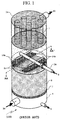
- Fig. 1 shows a packed tower 100 of recent prior art, having distribution trough network 1a and an overhead feed distribution network 3a.
- Sulphuric acid is distributed into distribution troughs 1a at multiple feed points 14a to reduce its velocity for acceptable erosion/corrosion rates, and also provide for a uniform distribution.
- the recent use of superior corrosion resistant high silicon austenitic stainless steel as the material of construction has reduced the size of distributor troughs 1a due to higher allowed velocities, flow capacity limitations occur in providing a uniform flow distribution and, thus, multiple feed points 14a are still required to reduce velocity for acceptable uniformity of flow distribution.
- a horizontal cross-section view of tower 100 shown as plane AA-AA' in Fig. 1 is presented in Fig. 3 for greater detail of the prior art distribution troughs 1a and the feed distribution piping network 3a.
- Tower 200 shown in Fig. 2 has two liquid distribution troughs 1 according to the invention.
- Troughs 1 distribute inlet liquid flow 8 uniformly across the top of packing shown as 6 supported by packing support 5. Liquid flows downward and exits tower 200 as the exit liquid flow 9.
- inlet SO 3 -containing gas flow 10 enters tower 200 into vestibule 4. The gas travels upwards through packing support 5 and packing 6 where heat and/or mass transfer occurs between the sulphuric acid and the SO 3 containing gas. SO 3 -depleted gas then passes past the liquid distribution system comprising the simple inlet feed conduit network 3 and improved distribution troughs 1 having single inlets 14 and flow deflectors 19 of use according to the invention.
- Fig. 3 shows a tower plan view at cross-section plane AA-AA' of Fig. 1 , having two distribution troughs 1a according to the prior art, each having multiple inlets 14a and, on trough side ledges 24, multiple submerged orifices 12, under which downcomer tubes 13 are attached for directing distribution trough exit flows over the entire cross-sectional area and down to packing 6.
- Feed liquid flow 8 is distributed through the feed distribution piping network 3a to multiple inlets 14a of prior art distribution troughs 1a.
- feed distribution piping network 3a comprises a central feed conduit and smaller branching feed conduits.
- the number of multiple inlets 14a is chosen for distributing smaller inlet flows as the number of inlets 14a is increased to thereby cause lower velocities throughout the length of distribution troughs 1a.
- Lower velocities throughout the length of prior art distribution troughs 1a were necessary to ensure an even distribution of liquid. In older prior art distribution troughs constructed of ductile iron, lower velocities were also necessary to avoid accelerated wear. More detail for the outlined portion VV in Fig. 3 , below feed distribution piping network 3a, is shown in the enlarged view of Fig. 5 and subsequent cross-sectional views of Figs. 7 and 9 .
- Fig. 4 shows two distribution troughs 1 according to the invention, each having its own single inlet 14 and, on trough side ledges 24, multiple submerged orifices 12, under which downcomer tubes 13 are attached for directing distribution trough exit flows over the entire cross-sectional area and down to the packing 6.
- Feed liquid flow 8 is distributed through feed distribution piping network 3 to single inlets 14 of improved distribution troughs 1, according to the invention.
- feed distribution piping network 3 comprises only a central feed conduit.
- Improved distribution trough 1 is shown to include a partitioning plate or plates 15, lying attached to and overlapping the inside edges of ledges 24, and which divide improved distribution trough 1 into an upper open section 17 above ledges 24 and a lower trough section 18 under partitioning plate or plates 15.
- inlet pipe 14 is connected into lower section 18.
- the inlet flow into lower trough section 18 passes through apertures 16 of partitioning plate/plates 15, which apertures are covered by flow deflectors 19 in this view into upper section 17. More detail for the outlined portion V, below feed distribution piping network 3, is shown in the enlarged view of Fig. 6 and subsequent cross-sectional views of Figs. 8 and 10 .
- Fig. 5 enlargement of Fig. 3 plan-view outlined portion VV, shows two of multiple inlets. 14a into prior art distribution trough 1a.
- the vertical cross-section view BB-BB' as located in Fig. 5
- Fig. 7 for comparison with a similar cross-section side view in distribution trough 1 of the invention.
- the vertical cross-section view CC-CC' as located in Fig. 7
- Fig. 9 is projected in Fig. 9 .
- Fig. 6 enlargement of Fig. 4 plan-view outlined portion V, indicates horizontal partition plate/plates 15 that create lower trough section 18, attached onto horizontal side ledges 24 of trough 1 where multiple submerged orifices 12 are located such that all orifices 12 have a common liquid height above.
- Horizontal partition plates 15 incorporate deflectors 19, a significant feature of the invention, appearing as rectangles from above and which cover apertures 16 in plate/plates 15.
- the vertical cross-section view B-B' as located in Fig. 6
- Fig. 8 is projected in Fig. 8 to best illustrate side views of deflectors 19 and flow patterns due to deflector and baffle features of the invention.
- the vertical cross-section view C-C' as located in Fig. 6
- Fig. 10 is projected in Fig. 10 to best illustrate the horizontal ledges 24 and face view of a typical deflector assembly 19.
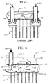
- Fig. 7 longitudinal cross-section BB-BB' from Fig. 5 , shows a portion of a distribution trough 1a according to the recent prior art, wherein multiple inlets 14a provide divided sulphuric acid inlet flows 23a into the lower region.
- multiple inlets 14a provide divided sulphuric acid inlet flows 23a into the lower region.
- the included downcomers 13 are shown, behind the trough wall with dashed lines, to extend up to the side horizontal ledge 24 where the downcomers are in fluid communication with submerged orifices (not shown) while submerged orifices 12 are shown in Fig. 9 .
- the multiplicity of divided inlet flows 23a into trough 1a provide for low velocities suitable for ensuring even distribution of discharge flows along the length of distribution trough 1a.
- Fig. 8 longitudinal cross-section B-B' from Fig. 6 , shows the two sections of improved distribution trough 1 as upper section 17 and a lower section 18, separated by a horizontal partitioning plate or plates 15, which are attached on the inside edges of horizontal ledges 24.
- the liquid height in upper section 17 is not shown.
- a majority of downcomers 13 has been removed while included downcomers 13 are truncated. Upward extension of the included downcomers to the horizontal side ledge 24 has been not be shown.
- Fig. 7 shows the extension as dashed lines.
- Inlet liquid feed distribution conduit 3 ( Fig. 2 ) directs a liquid flow portion 23a, shown in Fig.
- each distribution trough 1 by means of a single pipe inlet 14 ( Figs. 2 , 4 , 6 and 8 ).
- the inlet pipe diameter is constrained by the width of lower section 18 of trough 1.
- Flow arrows 23 (a through e) show the general direction of sulphuric acid fluid flow. Flow 23e through openings 16 is redirected by deflectors 19, first upwards and then back along the lower surface of upper section 17, opposite to its horizontal inlet direction of travel in the lower section.
- inlet flow 23a impacts the far wall, generally the bottom floor of the trough, flow arrow 23b, and preferentially flows along the floor.
- a minimum of one such baffle 22 on either side of flow inlet 23b is required on the impacted floor.
- Inlet baffle 22 has been found to be important for inducing turbulence that helps to provide a more uniform velocity profile across the enclosed lower trough section 18.
- Other profiles for baffle 22 may also be used provided that they disrupt the preferential flow along the wall opposing the inlet pipe and, preferably, induce turbulence.
- baffles 20 are conveniently fabricated and installed but, some are scaled to adjust the flow rate through each opening 16 in long distributors.
- Baffles 20 functions at any elevation between the bottom and separating plate 15 in lower trough section 18.
- baffles 20 are located at the bottom of horizontal partitioning plates 15 so that a deflector 19, partitioning plate 15, and vertical baffle 20 can be fabricated from a single piece of formable material.
- High silicon austenitic stainless steel is the preferred material in towers for sulphuric acid production and can be formed into plates incorporating several features, as shown in Fig. 11 , using bending and cutting machines.
- Each of baffles 20 also redirects sulphuric acid flow within lower trough section 18, as illustrated by flow arrow 23d.
- these baffles 20 also induce turbulence that provides a more uniform liquid flow profile in lower trough section 18. In ductile iron distributors of prior art for sulphuric acid service, this turbulence would quickly corrode the exposed surfaces.
- deflectors assemblies 19 are provided at the downstream edge of openings 16. In the absence of deflector assemblies 19, high inlet flow velocities cause flow through one opening 16 to continue in the horizontal direction and add to horizontal liquid flow from the next opening 16. This results in the surface height of the liquid to be higher at the far ends of trough 1 than at the center in a stationary pattern and high upward velocity causes significant local liquid level disturbances.
- Deflectors 19 provide obstruction across both the horizontal and upward directions of flow, and are located at openings 16 to maintain low average velocity in upper section 17 by directing flows through openings 16 into a horizontal, but reverse direction, 23e, along the bottom surfaces of upper trough section 17. A significant benefit is found in keeping the reverse horizontal liquid flow with an average velocity that is sufficient to maintain a shear force to sweep away settling solids.
- FIG. 9 cross-section view CC-CC' of Fig. 5 , is a side-to-side cross-section through inlet pipe 14a and distribution trough 1a of recent prior art showing the use of many submerged orifices 12, which are located at a common elevation on horizontal wall sections 24 of trough 1a.
- This case of recent prior art shows no dividing partition for two trough sections although inlet pipes 14a are shown to extend into lower portion 18a of the trough.
- the prior art uses a multiplicity of inlet pipes 14a to provide many divided inlet flows 23a into trough for low velocities suitable for ensuring even distribution of liquid discharge flows along the length of distribution trough 1a.
- Fig. 10 cross-section view C-C' of Fig. 6 , is a side-to-side cross-section of the improved distribution trough 1 through a typical opening 16, (see Fig. 8 ) showing that deflector 19 spans the entire width of lower section 18 of trough 1 with side overlap above horizontal dividing wall plates 15.
- Liquid flow up-ward directing baffles 20 are shown located at the top of lower section 18.
- the cross-section as shown in Fig. 10 shows the use of many submerged orifices 12 located at a common elevation on horizontal side ledges 24 of trough 1.
- Flow arrows indicate typical flow paths into upper section 17 and into submerged orifices 12, as well as indicating back-eddy currents that maintain suspension of fine particles, and a sweeping action for re-entrainment of settled solids.
- horizontal partitioning plate or plates 15 between lower 18 and upper sections 17 is also used to support screens or similar filtering devices in openings 16 to restrain large solids particles entrained in the inlet flow in lower section 18.
- the size of screen openings are chosen to pass solids that are small enough to avoid blockage of orifices 12, i.e. less than the orifice size and, preferably, less than one fifth of the orifice size.
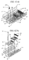
- Figs. 11a and 11b illustrate a deflector assembly 19 and baffle 20 formed as parts of a particular plate section 27b of dividing partition plates 15, from a single piece of plate material or sheet metal.
- Other differently dimensioned and bent plate sections 27a, 27c, and 27d at the inlet of and at the end of a distribution trough 1 are illustrated in Figs. 12a, 12b , 13a and 13b .
- FIG. 11a particular plate 27b is cut to a suitable width and a length that includes lengths for horizontal and vertical portions 19a and 19b of deflector 19, a length portion for opening 16, and a length portion for lower section baffle 20.
- the so-prepared plate is bent along lines 28a, 28b, and 28c to form the profile illustrated in Fig. 11b.
- Figs. 11a and 11b illustrate a section of the horizontal plates with perforations 25 that are used for openings 16, and for support of finer screen 26, if necessary.
- a consistent length of partition plate between opening 16 and deflector 19 is preferred but is varied as necessary, e.g. the distance between the openings may be altered at the trough ends and center.
- particular plate 27b is further prepared with punched, drilled, or cut holes 29 for bolting assembly, having opening perforations 25, and removal of corners 30 for fitting baffle 20 into lower trough section 1.
- Figs. 12a, 12b , 13a and 13b do not include down comers that are attached under orifices 12.
- FIG. 12 isometric wire frame assembly and exploded views of an inlet portion of trough 1, shows partition plates 27b, as described above and another particular partitioning plate 27a that is used at central trough inlet 14 supplying inlet liquid flow 23a.
- Inlet partition plate 27a as shown is truncated but extends similarly in the opposite direction from inlet 14, i.e. symmetrically about centre-line 31.
- Partition plate 27a includes perforated end sections for the first of apertures 16 on either side of inlet 14.
- Partition plate 27a also incorporates inlet bottom baffle 22 as the lower part of an extended and bent portion 33 of partition plate 27a, having opening 32 passing liquid through lower section 18 of trough 1.
- Extended portion 33 with bottom baffle 22 may also be prepared as a separate piece and attached, e.g. welded to partition plate 27a.
- Figs 13a and 13b isometric wire frame assembly and exploded views of an end portion of trough 1, show two particular partition plates 27c and 27d forming the last sections of partitioning plates 15 before an end wall 36 of the trough.
- a perforated plate and/or screen 34 extending from separating plate to the bottom of the lower section 18 of trough 1 is included as a final means to filter and collect sedimentation.
- a diagonal perforated plate 34 or screen is preferably attached to one of the final separating plates 27c or 27d in trough 1 as shown on the second last plate 27c in Figs. 13a and 13b , so that plate 27c and diagonal screen 34 can be removed in unison for cleaning of any accumulated sedimentation.
- the preferred geometry is a general diagonal direction extending downwards from the rear of the penultimate aperture 16 to trough 1 bottom and extends towards the end of trough 1 such that solids are directed into a pocket where they can accumulate without preventing flow through the end openings. These are particularly useful during initial operation after new packing is introduced with some likely breakage creating larger sized solids.
- Figs. 12a, 12b , 13a and 13b also indicate the use of bolts 35 to hold some removable plates in place which is necessary to facilitate solids clean-out. Other plates are permanently fixed in place by welding.
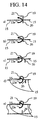
- deflectors 19 is not limited to the preferred angular form as shown in Fig. 8 and Fig. 14a but may also be, by way of example, of different curvilinear shapes as shown in Figs. 14b, c, d and e .
- the leading edge 21 of deflector 19 is shown to overlap an aperture 16 and a portion of partitioning plate 15.
- Fig. 14a and 14b show baffle 20 in lower trough section 18 to be aligned with deflector 19, while Fig. 14c, d and e also show different positions of vertical baffle 20 in lower trough section 18.
- Various geometries may be contemplated for the baffles and deflectors of use in the practise of the invention in accordance with the foregoing principles to allow for convenient fabrication and installation.
- the successful functioning of the present invention was discovered from experimental testing conducted using a small scale distributor trough.
- the small scale model was made of clear material to allow observation of liquid flow within trough 1 and to determine the overall performance of the distributor improvements compared to an equivalently sized model according to the prior art.
- the effects of individual features used in improved distributor 1 were also observed by inserting and removing various components. Test work was used to adjust computer simulation models for accurate reproduction and computer simulation gave further insight into the flow patterns and effects of experimentally added features.
- each added feature used in the improved distributor 2 was insufficient on its own per se to improve the overall performance of distributor 1. Thus, starting from an empty trough shell, each feature addressed a performance difficulty but often created a new one. The complete assembly of the improved distributor, according to the invention, was able to address all difficulties encountered.
- the number and diameter of inlet pipes into the distribution trough determined the inlet velocity for any given flow rate.
- the number of inlets to the distribution trough model was reduced from ten to one. As the number of inlets was reduced to one, a flow pattern developed which formed a standing wave near the inlet. This leads to a very non-uniform liquid surface height and distinct liquid level difference before and after the standing wave.
- a prior art feature comprising a partitioning plate having regularly spaced apertures to create an enclosed bottom section in fluid communication with an open upper section was installed and tested.
- the standing wave flow pattern near the central feed inlet did not reappear.
- flow rates through the partition apertures at the ends of the trough were substantially higher than the flow rates through the apertures closer to the central inlet.
- a stationary pattern of variable liquid height in the upper trough section was observed with the highest liquid levels at the outer ends of the trough, decreasing to the lowest level in the center.
- variable liquid surface height in the trough prevents the equal discharge flow rates through submerged orifices having equally sized opening diameter and other means to achieve equal discharge flows are impractical.
- Such means include adjusting orifice diameters for the different liquid surface heights but this would greatly limit the range of operating capacity.
- Baffles were introduced into the bottom section of the partitioned trough to balance flows through the apertures in the partitioning plate. Baffles were located both in the vicinity of each aperture and in the entrance region of the trough on the floor opposing the inlet flow. The baffles could be adjusted in position and size to achieve a reasonable balance of flows through the apertures.
- baffles on the trough floor near the inlet disrupted the initial preferential flow along the bottom by inducing turbulence and redistributing the flow currents throughout the lower section of the trough.
- the performance of the trough remained very similar to a trough with no baffles, i.e. high outer end liquid heights.
- a singular bottom baffle on each side of the entrance region was insufficient to properly distribute the flow through each aperture along the length of the trough, and an additional baffle in the vicinity of each aperture was found to be necessary.
Landscapes
- Chemical & Material Sciences (AREA)
- Chemical Kinetics & Catalysis (AREA)
- Engineering & Computer Science (AREA)
- Analytical Chemistry (AREA)
- General Chemical & Material Sciences (AREA)
- Oil, Petroleum & Natural Gas (AREA)
- Physical Or Chemical Processes And Apparatus (AREA)
- Feeding, Discharge, Calcimining, Fusing, And Gas-Generation Devices (AREA)
- Devices And Processes Conducted In The Presence Of Fluids And Solid Particles (AREA)
- Gas Separation By Absorption (AREA)
- Treating Waste Gases (AREA)
- Extraction Or Liquid Replacement (AREA)
- Vaporization, Distillation, Condensation, Sublimation, And Cold Traps (AREA)
Claims (15)
- Goulotte de distribution de liquide (1) pour distribuer un liquide contenu dans une tour en vue d'un échange massique ou thermique entre au moins un premier liquide et un deuxième fluide ;
ladite goulotte ayant une section supérieure (17) et une section inférieure (18) ;
ladite section inférieure (18) servant à recevoir ledit premier liquide ;
un organe de division horizontale (15) séparant ladite section supérieure (17) de ladite section inférieure (18) et ayant au moins une partie d'organes de division définissant une ouverture (16) pour permettre le passage dudit fluide liquide depuis ladite section inférieure (18) jusqu'à ladite section supérieure (17) ;
un moyen de conduite d'alimentation (14) en communication avec ladite section inférieure (18) pour fournir un premier flux de liquide (23b) dudit premier liquide vers ladite section inférieure (18) ;
ladite section inférieure (18) ayant au moins une partie d'entrée définissant une entrée de liquide en communication avec ledit moyen de conduite d'alimentation (14) ; et caractérisée en ce qu'elle comprend
une première chicane (22) adjacente à ladite partie d'entrée, et située sur le plancher de ladite goulotte (1), en regard dudit premier flux d'entrée, ladite première chicane (22) recevant en fonctionnement l'impact dudit premier flux de liquide (23b) et pour empêcher un écoulement préférentiel le long des parois de ladite goulotte et dudit organe de division (15). - Goulotte de distribution de liquide (1) selon la revendication 1, comprenant un ensemble d'au moins une deuxième chicane (20) adjacente à au moins l'une desdites ouvertures (16) de l'organe de division pour diriger une partie dudit premier flux de liquide à travers lesdites ouvertures (16) de l'organe de division jusque dans ladite section supérieure (17) de ladite goulotte.
- Goulotte de distribution de liquide (1) selon la revendication 1 ou la revendication 2, comprenant une pluralité de déflecteurs (19) à l'intérieur de ladite section supérieure (17), chacun desdits déflecteurs (19) étant situé en position adjacente à une ouverture (16) de l'organe de division et ayant une partie définissant une surface verticale et une partie définissant une surface horizontale pour effectuer une distribution essentiellement horizontale et uniforme du flux dudit premier liquide sur la surface inférieure de ladite section supérieure (17) de ladite goulotte (1).
- Goulotte de distribution de liquide (1) selon l'une quelconque des revendications 1 à 3, comprenant ladite section supérieure (17) ayant des parties définissant des sorties de décharge (12) choisies parmi des sorties du type déversoir ou du type à orifice immergé par lesquelles ledit premier liquide sort de ladite section supérieure (17) de ladite goulotte (1), et dans laquelle lesdites sorties de décharge communiquent de préférence avec des colonnes descendantes qui dirigent un premier flux de liquide.
- Goulotte de distribution de liquide (1) selon la revendication 4, dans laquelle lesdites sorties de décharge (12) desdites goulottes de distribution sont des sorties du type à orifice immergé situées sur ladite section de goulotte supérieure à une élévation commune, et dans laquelle lesdites sorties de décharge (12) communiquent de préférence avec des colonnes descendantes (13) qui dirigent le premier flux de liquide.
- Goulotte de distribution de liquide (1) selon l'une quelconque des revendications 1 à 5, dans laquelle ladite première chicane (22) est également positionnée en avant de ladite une ouverture (16) de manière à induire fonctionnellement une turbulence qui assure une vitesse plus uniforme sur toute la section transversale de la section inférieure de la goulotte et de manière à maintenir en suspension la plupart des matières solides entraînées.
- Goulotte de distribution de liquide (1) selon l'une quelconque des revendications 1 à 6, dans laquelle ledit ensemble d'au moins une deuxième chicane (20) est également positionné de manière à induire une turbulence le long de la longueur de la goulotte (1), qui assure une vitesse plus uniforme sur toute la section transversale de la section inférieure de la goulotte et de manière à maintenir en suspension la plupart des matières solides entraînées.
- Goulotte de distribution de liquide (1) selon l'une quelconque des revendications 3 à 7, dans laquelle ledit déflecteur (19) a une forme ayant des surfaces verticales et horizontales choisies parmi des faces planes et curvilignes, et dans laquelle ladite face verticale est perpendiculaire à l'axe longitudinal de la goulotte (1) le long duquel s'écoule ledit premier fluide et ladite face horizontale est perpendiculaire à l'axe vertical de la goulotte, et de préférence dans laquelle lesdits déflecteurs ont des extensions latérales des faces de forme angulaire ou curviligne perpendiculaires à l'axe longitudinal de la goulotte (1), lesquelles s'étendent au moins en partie vers les parois latérales de la section supérieure (17) de la goulotte (1).
- Goulotte de distribution de liquide (1) selon l'une quelconque des revendications 1 à 8, dans laquelle ledit organe de division comprend une plaque unitaire ayant lesdites ouvertures, ou comprend une pluralité de plaques constituant lesdites ouvertures entre des plaques adjacentes.
- Goulotte de distribution de liquide (1) selon l'une quelconque des revendications 2 à 9, dans laquelle chaque chicane dudit deuxième ensemble de chicanes (20) est alignée en position adjacente aux bords arrière avals des ouvertures (16) dans ledit organe de division (15), ou dans laquelle ledit deuxième ensemble de chicanes (20) est formé par une partie inférieure attachée ou une partie inférieure poursuivie desdits ensembles de déflecteurs (19), ladite partie inférieure s'étendant à travers lesdites ouvertures dans ladite section de goulotte inférieure (18), et dans laquelle ledit deuxième ensemble de chicanes (22) est formé par des parties desdites plaques optionnellement formées intégralement.
- Goulotte de distribution de liquide (1) selon l'une quelconque des revendications 1 à 10, comprenant en outre des cribles pour retenir des particules plus grandes que la taille desdites sorties de décharge (12), et de préférence pour retenir des particules plus grandes qu'environ un cinquième de la tailles desdites sorties de décharge, dans ladite section de goulotte inférieure (18), adjacente auxdites ouvertures (16).
- Goulotte de distribution de liquide (1) selon l'une quelconque des revendications 1 à 11, dans laquelle ledit moyen de conduite d'alimentation (14) comprend au moins une colonne descendante (13) pour chaque entrée de liquide dans ladite goulotte (1).
- Tour (200) pour un transfert massique et/ou thermique, comprenant une ou plusieurs sections prévues pour recevoir une garniture et incorporant une goulotte de distribution de liquide (1) selon l'une quelconque des revendications 1 à 12, ou un réseau desdites goulottes de distribution de liquide, ladite tour (200) étant de préférence utilisée comme tour d'absorption et/ou comme tour de séchage dans le processus de contact d'acide sulfurique, ou comme tour d'absorption dans un processus de capture de dioxyde de carbone.
- Usine d'acide sulfurique comprenant une tour d'absorption ou de séchage (200) ayant une goulotte de distribution de liquide (1) selon l'une quelconque des revendications 1 à 12, ou un réseau desdites goulottes de distribution de liquide (1).
- Usine de capture de dioxyde de carbone comprenant une tour d'absorption (200) ayant une goulotte de distribution de liquide (1) selon l'une quelconque des revendications 1 à 12, ou un réseau desdites goulottes de distribution de liquide (1).
Applications Claiming Priority (2)
| Application Number | Priority Date | Filing Date | Title |
|---|---|---|---|
| CA2689266A CA2689266A1 (fr) | 2009-12-23 | 2009-12-23 | Distributeur ameliore |
| PCT/CA2010/001946 WO2011075817A1 (fr) | 2009-12-23 | 2010-12-09 | Goulotte de distribution de liquide pouvant être utilisée dans des tours d'usines d'acide sulfurique et de captage de carbone |
Publications (3)
| Publication Number | Publication Date |
|---|---|
| EP2516031A1 EP2516031A1 (fr) | 2012-10-31 |
| EP2516031A4 EP2516031A4 (fr) | 2014-04-02 |
| EP2516031B1 true EP2516031B1 (fr) | 2016-03-02 |
Family
ID=44189463
Family Applications (1)
| Application Number | Title | Priority Date | Filing Date |
|---|---|---|---|
| EP10838450.4A Active EP2516031B1 (fr) | 2009-12-23 | 2010-12-09 | Goulotte de distribution de liquide pouvant être utilisée dans des tours d'usines d'acide sulfurique et de captage de carbone |
Country Status (12)
| Country | Link |
|---|---|
| US (1) | US9259665B2 (fr) |
| EP (1) | EP2516031B1 (fr) |
| CN (1) | CN102791346B (fr) |
| AU (1) | AU2010335964B9 (fr) |
| BR (1) | BR112012015206B1 (fr) |
| CA (2) | CA2689266A1 (fr) |
| CL (1) | CL2012001721A1 (fr) |
| IN (1) | IN2012DN05896A (fr) |
| MA (1) | MA33944B1 (fr) |
| PE (1) | PE20130360A1 (fr) |
| TN (1) | TN2012000299A1 (fr) |
| WO (1) | WO2011075817A1 (fr) |
Families Citing this family (15)
| Publication number | Priority date | Publication date | Assignee | Title |
|---|---|---|---|---|
| FR3016533B1 (fr) * | 2014-01-21 | 2016-01-15 | IFP Energies Nouvelles | Plateau distributeur pour colonne d'echange entre un gaz et un liquide avec deflecteur de liquide |
| DE102014105008B4 (de) * | 2014-04-08 | 2017-05-18 | Technische Universität Berlin | Flüssigkeitsverteiler und Anordnung |
| US9783431B2 (en) * | 2014-05-28 | 2017-10-10 | Katz Water Tech, Llc | Apparatus and method to remove contaminates from a fluid |
| CN104548643A (zh) * | 2014-11-28 | 2015-04-29 | 江门谦信化工发展有限公司 | 一种精馏塔回流装置 |
| CN105536683B (zh) * | 2015-12-16 | 2017-09-19 | 无锡福镁轻合金科技有限公司 | 一种用于石油化工塔的活动塔板 |
| US10427113B2 (en) | 2017-07-18 | 2019-10-01 | Cnh Industrial Canada, Ltd. | Horizontal product distribution system using static baffles in a distributor |
| US11034605B2 (en) | 2018-03-29 | 2021-06-15 | Katz Water Tech, Llc | Apparatus system and method to extract minerals and metals from water |
| US11713258B2 (en) | 2017-08-24 | 2023-08-01 | Katz Water Tech, Llc | Apparatus system and method to extract minerals and metals from water |
| US10864482B2 (en) | 2017-08-24 | 2020-12-15 | Katz Water Tech, Llc | Apparatus system and method to separate brine from water |
| CN110124459A (zh) * | 2018-02-09 | 2019-08-16 | 中石化广州工程有限公司 | 甲醇气水洗罐 |
| CN108408696B (zh) * | 2018-03-10 | 2021-07-23 | 宣达实业集团有限公司 | 带稳流多级过滤管式分酸器 |
| JP7243057B2 (ja) * | 2018-07-12 | 2023-03-22 | 株式会社Ihi | 気液接触装置 |
| KR102178891B1 (ko) * | 2020-05-18 | 2020-11-13 | 윤팔석 | 상,하류식 여과장치의 여재 유실 방지용 트러프 |
| EP4228788A1 (fr) * | 2020-12-21 | 2023-08-23 | Carbon Engineering Ltd. | Capture de dioxyde de carbone |
| CN113244741B (zh) * | 2021-04-27 | 2022-11-08 | 湖北灏瑞达环保能源科技有限公司 | 一种废气处理喷淋塔用液体收集用再分布器 |
Family Cites Families (46)
| Publication number | Priority date | Publication date | Assignee | Title |
|---|---|---|---|---|
| US3006623A (en) * | 1958-12-29 | 1961-10-31 | Exxon Research Engineering Co | Fluid distributor for packed columns |
| US3146609A (en) * | 1964-04-27 | 1964-09-01 | Baltimore Aircoil Co Inc | Water distribution system |
| US3232590A (en) * | 1964-07-08 | 1966-02-01 | Us Stoneware Co | Treating tower having a plate for collecting, mixing and distributing liquid |
| US3419251A (en) * | 1965-06-21 | 1968-12-31 | Us Stoneware Inc | Distributor |
| US3392967A (en) * | 1965-12-20 | 1968-07-16 | Us Stoneware Inc | Trough-type distributor |
| US3360246A (en) * | 1966-02-25 | 1967-12-26 | Us Stoneware Inc | Distributor with bed-level limiter |
| US3591345A (en) * | 1968-11-13 | 1971-07-06 | Exxon Research Engineering Co | Gas quench device for mixed-phase reactors |
| US4272026A (en) * | 1978-10-24 | 1981-06-09 | Biuro Studiow, projetow i Realizacji in Westycji Przemyslu Nieorganicznego "Biprokawas" | Sprinkling device for absorption towers |
| CA1120396A (fr) * | 1979-01-09 | 1982-03-23 | Rolf P.C. Manteufel | Dispositif d'amenee de liquides dans des colonnes d'echange thermique |
| FR2493718A1 (fr) * | 1980-11-12 | 1982-05-14 | Hamon | Dispositif pour recueillir un liquide tombant librement et son application a une installation de mise en contact a contre-courant d'un liquide avec un gaz |
| US4432913A (en) * | 1981-08-31 | 1984-02-21 | The Dow Chemical Company | Liquid distributing apparatus and method for a liquid-vapor contact column |
| DE3141930C2 (de) * | 1981-10-22 | 1986-07-10 | Julius Montz Gmbh, 4010 Hilden | Verteilerboden für eine Austauschkolonne |
| CH658198A5 (de) * | 1983-01-04 | 1986-10-31 | Sulzer Ag | Fluessigkeitsverteiler in einer stoff- und waermeaustauschkolonne. |
| US4476069A (en) * | 1983-02-23 | 1984-10-09 | The Dow Chemical Company | Liquid distributing apparatus for a liquid-vapor contact column |
| US4689183A (en) * | 1985-12-02 | 1987-08-25 | The Dow Chemical Company | Ultra low flow rate liquid redistributor assembly for use in a liquid-vapor contact tower |
| US4729857A (en) * | 1987-04-27 | 1988-03-08 | Glitsch, Inc. | Liquid distributor for packed tower |
| US4839108A (en) * | 1987-12-21 | 1989-06-13 | Mobil Oil Corp. | Liquid distribution device and pan |
| US4816191A (en) * | 1988-01-19 | 1989-03-28 | Koch Engineering Company, Inc. | Distributor for liquid-gas contact column and method of preparation and use |
| US4846266A (en) * | 1988-09-09 | 1989-07-11 | Norsaire Systems | Header assembly for plate-type evaporative heat exchangers |
| US5051214A (en) * | 1989-01-13 | 1991-09-24 | Glitsch, Inc. | Double-deck distributor and method of liquid distribution |
| US4994210A (en) * | 1990-03-01 | 1991-02-19 | Koch Engineering Company, Inc. | High efficiency distributor for gas-liquid contact column and method of preparation and use |
| US5014740A (en) * | 1990-05-21 | 1991-05-14 | Cameron Gordon M | Distributor for packed tower |
| US4991646A (en) * | 1990-05-23 | 1991-02-12 | General Motors Corporation | Air flow distribution baffle |
| US5061407A (en) * | 1990-08-08 | 1991-10-29 | Nutter Dale E | Liquid distributor for gas-liquid contact apparatus |
| US5233843A (en) * | 1991-07-01 | 1993-08-10 | The United States Of America As Represented By The Secretary Of The Navy | Atmospheric moisture collection device |
| US5240652A (en) * | 1992-10-08 | 1993-08-31 | Praxair Technology, Inc. | Liquid distributor for a vapor-liquid contacting column |
| AR004048A1 (es) * | 1995-10-20 | 1998-09-30 | Inst Francais Du Petrole | Un dispositivo para distribuir, mezclar, y/o extraer varios fluidos en procesos de cromatografia y una columna cromatrografica que utiliza dicho dispositivo |
| US5884658A (en) * | 1996-09-05 | 1999-03-23 | Cameron; Gordon M. | Liquid distributor for a packed tower |
| US5906773A (en) * | 1997-07-30 | 1999-05-25 | Norton Company | Liquid distributor |
| US5919405A (en) * | 1997-10-23 | 1999-07-06 | Monsanto Company | Fluid distribution system for an absorption tower |
| JP2000126503A (ja) * | 1998-10-28 | 2000-05-09 | Sulzer Orthopedics Ltd | カラム充填用液体分配器 |
| ES2237070T3 (es) * | 1998-11-30 | 2005-07-16 | Sulzer Chemtech Ag | Columna a contracorriente con distribuidor de liquido. |
| US6527258B2 (en) * | 1999-03-19 | 2003-03-04 | Sulzer Chemtech Ag | Apparatus for the collection and distribution of liquid in a column |
| FI106297B (fi) * | 1999-04-01 | 2001-01-15 | Hadwaco Ltd Oy | Menetelmä liuoksen haihduttamiseksi sekä menetelmässä käytettävä haihdutin |
| AU2001231751A1 (en) * | 2000-02-16 | 2001-08-27 | Shell Internationale Research Maatschappij B.V. | Gas-liquid tray |
| US6722639B2 (en) * | 2001-04-10 | 2004-04-20 | Koch-Glitsch, Lp | Liquid distributor in mass transfer column and method of installation and use |
| CA2379558C (fr) * | 2001-05-23 | 2006-10-03 | Sulzer Chemtech Ag | Distributeur de liquide pour colonnes |
| US6758463B2 (en) * | 2001-11-21 | 2004-07-06 | Air Products And Chemicals, Inc. | Liquid distributor internal baffling |
| DE10341896A1 (de) * | 2003-09-10 | 2005-04-14 | Uhde Gmbh | Mehrphasen-Flüssigkeitsverteiler für einen Rieselbettreaktor |
| US7125004B2 (en) * | 2003-12-15 | 2006-10-24 | Koch-Glitsch, Lp | Liquid distributor for use in mass transfer column |
| DE102005045745A1 (de) * | 2005-09-23 | 2007-04-12 | Degussa Ag | Vorrichtung und Verfahren zur Verteilung zweier nicht miteinander mischbarer Flüssigkeiten |
| CA2715733A1 (fr) * | 2009-11-24 | 2011-05-24 | Sulzer Chemtech Ag | Dispositif d'admission de fluide |
| FR2978679B1 (fr) * | 2011-08-03 | 2014-01-17 | Total Raffinage Marketing | Plateau distributeur d'un gaz et d'un liquide, reacteur equipe d'un tel plateau et utilisation dudit plateau. |
| KR101351637B1 (ko) * | 2012-03-23 | 2014-01-16 | (주)에이엠티퍼시픽 | 액체 분배장치 |
| US9089787B2 (en) * | 2012-12-14 | 2015-07-28 | Koch-Glitsch, Lp | Distributor in mass transfer column and method of use |
| US9004460B2 (en) * | 2013-06-21 | 2015-04-14 | Praxair Technology, Inc. | Combined collector and distributor |
-
2009
- 2009-12-23 CA CA2689266A patent/CA2689266A1/fr not_active Abandoned
-
2010
- 2010-12-09 EP EP10838450.4A patent/EP2516031B1/fr active Active
- 2010-12-09 MA MA35091A patent/MA33944B1/fr unknown
- 2010-12-09 CA CA2784673A patent/CA2784673C/fr active Active
- 2010-12-09 CN CN201080064660.6A patent/CN102791346B/zh active Active
- 2010-12-09 AU AU2010335964A patent/AU2010335964B9/en active Active
- 2010-12-09 IN IN5896DEN2012 patent/IN2012DN05896A/en unknown
- 2010-12-09 PE PE2012000878A patent/PE20130360A1/es active IP Right Grant
- 2010-12-09 BR BR112012015206-8A patent/BR112012015206B1/pt active IP Right Grant
- 2010-12-09 WO PCT/CA2010/001946 patent/WO2011075817A1/fr active Application Filing
- 2010-12-09 US US13/516,762 patent/US9259665B2/en active Active
-
2012
- 2012-06-13 TN TNP2012000299A patent/TN2012000299A1/en unknown
- 2012-06-22 CL CL2012001721A patent/CL2012001721A1/es unknown
Also Published As
| Publication number | Publication date |
|---|---|
| MA33944B1 (fr) | 2013-01-02 |
| CA2689266A1 (fr) | 2011-06-23 |
| TN2012000299A1 (en) | 2013-12-12 |
| BR112012015206A2 (pt) | 2016-04-05 |
| PE20130360A1 (es) | 2013-04-03 |
| CA2784673C (fr) | 2018-01-02 |
| WO2011075817A1 (fr) | 2011-06-30 |
| AU2010335964B2 (en) | 2014-10-02 |
| AU2010335964A1 (en) | 2012-07-26 |
| CA2784673A1 (fr) | 2011-06-30 |
| CN102791346A (zh) | 2012-11-21 |
| EP2516031A1 (fr) | 2012-10-31 |
| CN102791346B (zh) | 2015-02-25 |
| US9259665B2 (en) | 2016-02-16 |
| CL2012001721A1 (es) | 2012-12-14 |
| US20120280411A1 (en) | 2012-11-08 |
| EP2516031A4 (fr) | 2014-04-02 |
| IN2012DN05896A (fr) | 2015-09-18 |
| AU2010335964B9 (en) | 2014-10-30 |
| BR112012015206B1 (pt) | 2019-11-19 |
Similar Documents
| Publication | Publication Date | Title |
|---|---|---|
| EP2516031B1 (fr) | Goulotte de distribution de liquide pouvant être utilisée dans des tours d'usines d'acide sulfurique et de captage de carbone | |
| KR900007320B1 (ko) | 기액 접촉 장치 | |
| US8025718B2 (en) | Fluid inlet device, use, and method of retrofitting | |
| US5061407A (en) | Liquid distributor for gas-liquid contact apparatus | |
| EP1721660A1 (fr) | Dispositif de distribution pour réacteurs à courant descendant ayant au moins un conduit vertical subdivisé | |
| US6923852B2 (en) | Flue gas desulfurization system with a stepped tray | |
| US6080228A (en) | Gas transfer pipe arrangement | |
| KR20010023681A (ko) | 기액 접촉 트레이용 강수관 | |
| EP0124920B1 (fr) | Appareil de traitement des mélanges de liquide et de gaz | |
| RU2403961C1 (ru) | Способ и устройство для распределения жидкости | |
| KR101430272B1 (ko) | 3상 증기 분배기 | |
| EP1257334A1 (fr) | Plateau de contact gaz-liquide | |
| CA2371863A1 (fr) | Plateau a haute capacite permettant de mettre en contact une vapeur et un liquide | |
| US7445198B2 (en) | Apparatus and process for distributing liquid | |
| JPH0677683B2 (ja) | 液流分配装置及び方法 | |
| JPH04227002A (ja) | 向流コラム用のガス/液体配給装置 | |
| US7445199B2 (en) | Apparatus and process for distributing liquid | |
| CA2956735A1 (fr) | Systeme de fixation de tube de distribution ameliore destine a un distributeur d'acide sulfurique | |
| CN100408136C (zh) | 气体-液体接触装置 | |
| CN112770823B (zh) | 带孔板式塔及其改造方法 | |
| WO2013137463A1 (fr) | Séparateur | |
| GB2411366A (en) | Downcomers for slurry bubble column reactors |
Legal Events
| Date | Code | Title | Description |
|---|---|---|---|
| PUAI | Public reference made under article 153(3) epc to a published international application that has entered the european phase |
Free format text: ORIGINAL CODE: 0009012 |
|
| 17P | Request for examination filed |
Effective date: 20120706 |
|
| AK | Designated contracting states |
Kind code of ref document: A1 Designated state(s): AL AT BE BG CH CY CZ DE DK EE ES FI FR GB GR HR HU IE IS IT LI LT LU LV MC MK MT NL NO PL PT RO RS SE SI SK SM TR |
|
| DAX | Request for extension of the european patent (deleted) | ||
| A4 | Supplementary search report drawn up and despatched |
Effective date: 20140228 |
|
| RIC1 | Information provided on ipc code assigned before grant |
Ipc: B01D 3/00 20060101AFI20140224BHEP Ipc: B01D 53/26 20060101ALI20140224BHEP Ipc: B01D 53/18 20060101ALI20140224BHEP Ipc: B01J 19/32 20060101ALI20140224BHEP |
|
| GRAP | Despatch of communication of intention to grant a patent |
Free format text: ORIGINAL CODE: EPIDOSNIGR1 |
|
| INTG | Intention to grant announced |
Effective date: 20150722 |
|
| GRAS | Grant fee paid |
Free format text: ORIGINAL CODE: EPIDOSNIGR3 |
|
| GRAA | (expected) grant |
Free format text: ORIGINAL CODE: 0009210 |
|
| AK | Designated contracting states |
Kind code of ref document: B1 Designated state(s): AL AT BE BG CH CY CZ DE DK EE ES FI FR GB GR HR HU IE IS IT LI LT LU LV MC MK MT NL NO PL PT RO RS SE SI SK SM TR |
|
| REG | Reference to a national code |
Ref country code: GB Ref legal event code: FG4D |
|
| REG | Reference to a national code |
Ref country code: AT Ref legal event code: REF Ref document number: 777599 Country of ref document: AT Kind code of ref document: T Effective date: 20160315 Ref country code: CH Ref legal event code: EP |
|
| REG | Reference to a national code |
Ref country code: IE Ref legal event code: FG4D |
|
| REG | Reference to a national code |
Ref country code: DE Ref legal event code: R096 Ref document number: 602010030995 Country of ref document: DE |
|
| REG | Reference to a national code |
Ref country code: NL Ref legal event code: MP Effective date: 20160302 |
|
| REG | Reference to a national code |
Ref country code: LT Ref legal event code: MG4D |
|
| REG | Reference to a national code |
Ref country code: AT Ref legal event code: MK05 Ref document number: 777599 Country of ref document: AT Kind code of ref document: T Effective date: 20160302 |
|
| PG25 | Lapsed in a contracting state [announced via postgrant information from national office to epo] |
Ref country code: FI Free format text: LAPSE BECAUSE OF FAILURE TO SUBMIT A TRANSLATION OF THE DESCRIPTION OR TO PAY THE FEE WITHIN THE PRESCRIBED TIME-LIMIT Effective date: 20160302 Ref country code: HR Free format text: LAPSE BECAUSE OF FAILURE TO SUBMIT A TRANSLATION OF THE DESCRIPTION OR TO PAY THE FEE WITHIN THE PRESCRIBED TIME-LIMIT Effective date: 20160302 Ref country code: ES Free format text: LAPSE BECAUSE OF FAILURE TO SUBMIT A TRANSLATION OF THE DESCRIPTION OR TO PAY THE FEE WITHIN THE PRESCRIBED TIME-LIMIT Effective date: 20160302 Ref country code: NO Free format text: LAPSE BECAUSE OF FAILURE TO SUBMIT A TRANSLATION OF THE DESCRIPTION OR TO PAY THE FEE WITHIN THE PRESCRIBED TIME-LIMIT Effective date: 20160602 Ref country code: GR Free format text: LAPSE BECAUSE OF FAILURE TO SUBMIT A TRANSLATION OF THE DESCRIPTION OR TO PAY THE FEE WITHIN THE PRESCRIBED TIME-LIMIT Effective date: 20160603 |
|
| PG25 | Lapsed in a contracting state [announced via postgrant information from national office to epo] |
Ref country code: NL Free format text: LAPSE BECAUSE OF FAILURE TO SUBMIT A TRANSLATION OF THE DESCRIPTION OR TO PAY THE FEE WITHIN THE PRESCRIBED TIME-LIMIT Effective date: 20160302 Ref country code: RS Free format text: LAPSE BECAUSE OF FAILURE TO SUBMIT A TRANSLATION OF THE DESCRIPTION OR TO PAY THE FEE WITHIN THE PRESCRIBED TIME-LIMIT Effective date: 20160302 Ref country code: AT Free format text: LAPSE BECAUSE OF FAILURE TO SUBMIT A TRANSLATION OF THE DESCRIPTION OR TO PAY THE FEE WITHIN THE PRESCRIBED TIME-LIMIT Effective date: 20160302 Ref country code: LV Free format text: LAPSE BECAUSE OF FAILURE TO SUBMIT A TRANSLATION OF THE DESCRIPTION OR TO PAY THE FEE WITHIN THE PRESCRIBED TIME-LIMIT Effective date: 20160302 Ref country code: PL Free format text: LAPSE BECAUSE OF FAILURE TO SUBMIT A TRANSLATION OF THE DESCRIPTION OR TO PAY THE FEE WITHIN THE PRESCRIBED TIME-LIMIT Effective date: 20160302 Ref country code: SE Free format text: LAPSE BECAUSE OF FAILURE TO SUBMIT A TRANSLATION OF THE DESCRIPTION OR TO PAY THE FEE WITHIN THE PRESCRIBED TIME-LIMIT Effective date: 20160302 Ref country code: LT Free format text: LAPSE BECAUSE OF FAILURE TO SUBMIT A TRANSLATION OF THE DESCRIPTION OR TO PAY THE FEE WITHIN THE PRESCRIBED TIME-LIMIT Effective date: 20160302 |
|
| PG25 | Lapsed in a contracting state [announced via postgrant information from national office to epo] |
Ref country code: IS Free format text: LAPSE BECAUSE OF FAILURE TO SUBMIT A TRANSLATION OF THE DESCRIPTION OR TO PAY THE FEE WITHIN THE PRESCRIBED TIME-LIMIT Effective date: 20160702 Ref country code: EE Free format text: LAPSE BECAUSE OF FAILURE TO SUBMIT A TRANSLATION OF THE DESCRIPTION OR TO PAY THE FEE WITHIN THE PRESCRIBED TIME-LIMIT Effective date: 20160302 |
|
| PG25 | Lapsed in a contracting state [announced via postgrant information from national office to epo] |
Ref country code: SK Free format text: LAPSE BECAUSE OF FAILURE TO SUBMIT A TRANSLATION OF THE DESCRIPTION OR TO PAY THE FEE WITHIN THE PRESCRIBED TIME-LIMIT Effective date: 20160302 Ref country code: CZ Free format text: LAPSE BECAUSE OF FAILURE TO SUBMIT A TRANSLATION OF THE DESCRIPTION OR TO PAY THE FEE WITHIN THE PRESCRIBED TIME-LIMIT Effective date: 20160302 Ref country code: RO Free format text: LAPSE BECAUSE OF FAILURE TO SUBMIT A TRANSLATION OF THE DESCRIPTION OR TO PAY THE FEE WITHIN THE PRESCRIBED TIME-LIMIT Effective date: 20160302 Ref country code: PT Free format text: LAPSE BECAUSE OF FAILURE TO SUBMIT A TRANSLATION OF THE DESCRIPTION OR TO PAY THE FEE WITHIN THE PRESCRIBED TIME-LIMIT Effective date: 20160704 Ref country code: SM Free format text: LAPSE BECAUSE OF FAILURE TO SUBMIT A TRANSLATION OF THE DESCRIPTION OR TO PAY THE FEE WITHIN THE PRESCRIBED TIME-LIMIT Effective date: 20160302 |
|
| REG | Reference to a national code |
Ref country code: DE Ref legal event code: R097 Ref document number: 602010030995 Country of ref document: DE |
|
| REG | Reference to a national code |
Ref country code: FR Ref legal event code: PLFP Year of fee payment: 7 |
|
| PG25 | Lapsed in a contracting state [announced via postgrant information from national office to epo] |
Ref country code: IT Free format text: LAPSE BECAUSE OF FAILURE TO SUBMIT A TRANSLATION OF THE DESCRIPTION OR TO PAY THE FEE WITHIN THE PRESCRIBED TIME-LIMIT Effective date: 20160302 |
|
| PLBE | No opposition filed within time limit |
Free format text: ORIGINAL CODE: 0009261 |
|
| STAA | Information on the status of an ep patent application or granted ep patent |
Free format text: STATUS: NO OPPOSITION FILED WITHIN TIME LIMIT |
|
| PG25 | Lapsed in a contracting state [announced via postgrant information from national office to epo] |
Ref country code: DK Free format text: LAPSE BECAUSE OF FAILURE TO SUBMIT A TRANSLATION OF THE DESCRIPTION OR TO PAY THE FEE WITHIN THE PRESCRIBED TIME-LIMIT Effective date: 20160302 |
|
| 26N | No opposition filed |
Effective date: 20161205 |
|
| PG25 | Lapsed in a contracting state [announced via postgrant information from national office to epo] |
Ref country code: SI Free format text: LAPSE BECAUSE OF FAILURE TO SUBMIT A TRANSLATION OF THE DESCRIPTION OR TO PAY THE FEE WITHIN THE PRESCRIBED TIME-LIMIT Effective date: 20160302 Ref country code: BG Free format text: LAPSE BECAUSE OF FAILURE TO SUBMIT A TRANSLATION OF THE DESCRIPTION OR TO PAY THE FEE WITHIN THE PRESCRIBED TIME-LIMIT Effective date: 20160602 |
|
| REG | Reference to a national code |
Ref country code: FR Ref legal event code: RU Effective date: 20170329 |
|
| REG | Reference to a national code |
Ref country code: CH Ref legal event code: PL |
|
| REG | Reference to a national code |
Ref country code: FR Ref legal event code: D7 Effective date: 20170724 |
|
| PG25 | Lapsed in a contracting state [announced via postgrant information from national office to epo] |
Ref country code: MC Free format text: LAPSE BECAUSE OF FAILURE TO SUBMIT A TRANSLATION OF THE DESCRIPTION OR TO PAY THE FEE WITHIN THE PRESCRIBED TIME-LIMIT Effective date: 20160302 |
|
| REG | Reference to a national code |
Ref country code: IE Ref legal event code: MM4A |
|
| PG25 | Lapsed in a contracting state [announced via postgrant information from national office to epo] |
Ref country code: LU Free format text: LAPSE BECAUSE OF NON-PAYMENT OF DUE FEES Effective date: 20161209 Ref country code: LI Free format text: LAPSE BECAUSE OF NON-PAYMENT OF DUE FEES Effective date: 20161231 Ref country code: CH Free format text: LAPSE BECAUSE OF NON-PAYMENT OF DUE FEES Effective date: 20161231 |
|
| PG25 | Lapsed in a contracting state [announced via postgrant information from national office to epo] |
Ref country code: IE Free format text: LAPSE BECAUSE OF NON-PAYMENT OF DUE FEES Effective date: 20161209 |
|
| REG | Reference to a national code |
Ref country code: FR Ref legal event code: PLFP Year of fee payment: 8 |
|
| PG25 | Lapsed in a contracting state [announced via postgrant information from national office to epo] |
Ref country code: HU Free format text: LAPSE BECAUSE OF FAILURE TO SUBMIT A TRANSLATION OF THE DESCRIPTION OR TO PAY THE FEE WITHIN THE PRESCRIBED TIME-LIMIT; INVALID AB INITIO Effective date: 20101209 Ref country code: CY Free format text: LAPSE BECAUSE OF FAILURE TO SUBMIT A TRANSLATION OF THE DESCRIPTION OR TO PAY THE FEE WITHIN THE PRESCRIBED TIME-LIMIT Effective date: 20160302 |
|
| PG25 | Lapsed in a contracting state [announced via postgrant information from national office to epo] |
Ref country code: MK Free format text: LAPSE BECAUSE OF FAILURE TO SUBMIT A TRANSLATION OF THE DESCRIPTION OR TO PAY THE FEE WITHIN THE PRESCRIBED TIME-LIMIT Effective date: 20160302 Ref country code: TR Free format text: LAPSE BECAUSE OF FAILURE TO SUBMIT A TRANSLATION OF THE DESCRIPTION OR TO PAY THE FEE WITHIN THE PRESCRIBED TIME-LIMIT Effective date: 20160302 |
|
| PG25 | Lapsed in a contracting state [announced via postgrant information from national office to epo] |
Ref country code: MT Free format text: LAPSE BECAUSE OF NON-PAYMENT OF DUE FEES Effective date: 20161209 |
|
| PG25 | Lapsed in a contracting state [announced via postgrant information from national office to epo] |
Ref country code: AL Free format text: LAPSE BECAUSE OF FAILURE TO SUBMIT A TRANSLATION OF THE DESCRIPTION OR TO PAY THE FEE WITHIN THE PRESCRIBED TIME-LIMIT Effective date: 20160302 |
|
| PGFP | Annual fee paid to national office [announced via postgrant information from national office to epo] |
Ref country code: GB Payment date: 20221223 Year of fee payment: 13 |
|
| PGFP | Annual fee paid to national office [announced via postgrant information from national office to epo] |
Ref country code: FR Payment date: 20231221 Year of fee payment: 14 Ref country code: DE Payment date: 20231214 Year of fee payment: 14 |
|
| PGFP | Annual fee paid to national office [announced via postgrant information from national office to epo] |
Ref country code: BE Payment date: 20231220 Year of fee payment: 14 |