EP2515638B1 - Bait dispenser - Google Patents
Bait dispenser Download PDFInfo
- Publication number
- EP2515638B1 EP2515638B1 EP10793028.1A EP10793028A EP2515638B1 EP 2515638 B1 EP2515638 B1 EP 2515638B1 EP 10793028 A EP10793028 A EP 10793028A EP 2515638 B1 EP2515638 B1 EP 2515638B1
- Authority
- EP
- European Patent Office
- Prior art keywords
- container
- dispenser
- plunger
- bait
- bait dispenser
- Prior art date
- Legal status (The legal status is an assumption and is not a legal conclusion. Google has not performed a legal analysis and makes no representation as to the accuracy of the status listed.)
- Active
Links
- XLYOFNOQVPJJNP-UHFFFAOYSA-N water Substances O XLYOFNOQVPJJNP-UHFFFAOYSA-N 0.000 claims description 26
- 241000276420 Lophius piscatorius Species 0.000 claims description 6
- 239000004743 Polypropylene Substances 0.000 claims description 3
- DHKHKXVYLBGOIT-UHFFFAOYSA-N acetaldehyde Diethyl Acetal Natural products CCOC(C)OCC DHKHKXVYLBGOIT-UHFFFAOYSA-N 0.000 claims description 3
- 125000002777 acetyl group Chemical class [H]C([H])([H])C(*)=O 0.000 claims description 3
- -1 polypropylene Polymers 0.000 claims description 3
- 229920001155 polypropylene Polymers 0.000 claims description 3
- 230000006641 stabilisation Effects 0.000 claims description 2
- 230000003014 reinforcing effect Effects 0.000 claims 1
- 238000005266 casting Methods 0.000 description 10
- 241000251468 Actinopterygii Species 0.000 description 6
- 238000005188 flotation Methods 0.000 description 6
- 239000003550 marker Substances 0.000 description 6
- 238000010276 construction Methods 0.000 description 4
- 239000000945 filler Substances 0.000 description 3
- 239000000463 material Substances 0.000 description 3
- 229910000639 Spring steel Inorganic materials 0.000 description 2
- 238000011068 loading method Methods 0.000 description 2
- 238000000034 method Methods 0.000 description 2
- 239000004033 plastic Substances 0.000 description 2
- 229920003023 plastic Polymers 0.000 description 2
- 230000035939 shock Effects 0.000 description 2
- 239000003381 stabilizer Substances 0.000 description 2
- 230000001154 acute effect Effects 0.000 description 1
- 230000008901 benefit Effects 0.000 description 1
- 230000009172 bursting Effects 0.000 description 1
- 230000015556 catabolic process Effects 0.000 description 1
- 238000004140 cleaning Methods 0.000 description 1
- 238000006731 degradation reaction Methods 0.000 description 1
- 230000004069 differentiation Effects 0.000 description 1
- 239000006260 foam Substances 0.000 description 1
- 238000010348 incorporation Methods 0.000 description 1
- 238000007373 indentation Methods 0.000 description 1
- 239000004615 ingredient Substances 0.000 description 1
- 230000013011 mating Effects 0.000 description 1
- 239000011159 matrix material Substances 0.000 description 1
- 230000007246 mechanism Effects 0.000 description 1
- 230000008569 process Effects 0.000 description 1
- 230000000452 restraining effect Effects 0.000 description 1
- 230000035945 sensitivity Effects 0.000 description 1
- 239000002195 soluble material Substances 0.000 description 1
- 238000011144 upstream manufacturing Methods 0.000 description 1
- 230000000007 visual effect Effects 0.000 description 1
Images


Classifications
-
- A—HUMAN NECESSITIES
- A01—AGRICULTURE; FORESTRY; ANIMAL HUSBANDRY; HUNTING; TRAPPING; FISHING
- A01K—ANIMAL HUSBANDRY; AVICULTURE; APICULTURE; PISCICULTURE; FISHING; REARING OR BREEDING ANIMALS, NOT OTHERWISE PROVIDED FOR; NEW BREEDS OF ANIMALS
- A01K97/00—Accessories for angling
- A01K97/02—Devices for laying ground-bait, e.g. chum dispensers, e.g. also for throwing ground-bait
-
- A—HUMAN NECESSITIES
- A01—AGRICULTURE; FORESTRY; ANIMAL HUSBANDRY; HUNTING; TRAPPING; FISHING
- A01K—ANIMAL HUSBANDRY; AVICULTURE; APICULTURE; PISCICULTURE; FISHING; REARING OR BREEDING ANIMALS, NOT OTHERWISE PROVIDED FOR; NEW BREEDS OF ANIMALS
- A01K91/00—Lines
- A01K91/06—Apparatus on lines not otherwise provided for, e.g. automatic hookers
Definitions
- the present invention relates to an angling accessory for placing ground bait at a particular location in a stretch of water when angling.
- the present invention provides means for an angler to place ground bait at a desired location in a stretch of water when about to fish.
- European Patent Specification 2244564 describes bait dispensers which represent a considerable advance in the art.
- the present invention relates to improvements to dispensers described in that patent.
- Japanese Patent Publication number H8-131034 A describes a fishing bait basket having two parts hinged together at the top and a fastener openable by a pressure sensitive plate.
- Japanese Patent Publication 52 - 163594 U discloses a bait dispensing float in hemispherical form and opening means.
- US Patent Specification 3,163,957 discloses a substantially ball-shaped bait and/or hooked line dispensing float with an openable base.
- a bait dispenser for use by an angler comprises, according to claim 1, a container into which bait can be loaded, the container attachable to a line and comprising two container parts with, at a proximal rear end thereof, flight stabilisation fins of which a pair thereof hinge the two container parts together at a trailing edge thereof, a spring arranged for urging the dispenser open and catch means arranged for holding the container closed until impact with water, characterised by a stop member formed on the trailing edge of the non-hinged fins and arranged via abutment on a substantially rigid line attachment arm extending from the rear end of the container to limit the opening of the two container parts.
- the two container parts are preferably similar, that is, are two substantially similar halves.
- the value of limiting the opening of the container to something between 35° to 55°, preferably 45°, is that while such opening should ensure that the bait is fully dispensed it also facilitates reeling the dispenser in again in a controlled manner, avoiding line knotting and entanglement and minimising water retention by the dispenser.
- a relatively smooth, rather than turbulent, reeling in operation with the dispenser aquaplaning over the surface of the water.
- the dispenser container parts are held open somewhat rigidly at the predetermined angle by the spring urging them outwards and the stop member preventing further opening.
- This enablement of smooth reeling in also means that the reeling in operation can be effected rapidly, thus minimising the time between dispensing ground bait and casting the definitive line, which can be particularly important when fishing in moving water.
- a relatively rigid arm extending from the rear of the container to an attachment member for attachment to the angler's line can assist in the smooth reeling in of the dispenser.
- This arm with attachment member may be of the order of 40-100mm, preferably 50 to 100mm long.
- By being attached to the hinge may advantageously have a greater freedom of angular movement about the hinge than in the plane occupied by the hinge.
- the angular freedom about the hinge may be 40°, but no more than 10° in the plane occupied by the hinge.
- the baited hook may be arranged for containment within the bait dispenser, so that dispersal of ground bait and deployment of the baited hook can occur simultaneously.
- the bait dispenser may be arranged, perhaps by means of a flotation chamber, built in or detachably fitted, to act as a float for indicating that there has been a bite.
- the attachment arm may be constructed and coloured as a float.
- the dispenser has an aerodynamic, teardrop, airship or barrage balloon shape, and a spring-loaded plunger mounted on one body half sited at a bow end thereof and incorporating a catch arranged to engage a detent on the other body half, whereby upon the dispenser striking water the plunger is driven to release the catch from the detent.
- the detent/catch construction is preferably such that only a very light force is required for opening such, in other words, that the dispenser remains closed during the casting operation but bursts open upon impact with the water even if the plunger itself scarcely makes contact with the water, if at all. In other words, it may be possible to do without a plunger and rely on hair spring operation to open the dispenser merely from the shock force generated by impact with the water. Differentiation between pre- and during casting situations and the water impact situation can be assisted by the two parts of the body being arranged to be separated slightly, for example by 0.1 to 0.5mm in the closed configuration when at rest and during casting, so that upon impact with the water the two parts will also impact upon each other.
- one container half carries a bulkhead upon which is mounted a plunger holder carrying a spring-loaded plunger, the plunger carrying a catch arranged to engage on a detent formed on the other container half, and the two container halves being formed with a mouth to which the plunger forms a continuum at the leading or bow end of the dispenser.
- the bulkhead which may be reinforced by brackets, also serves to assist in retaining the shape of the container half upon which it is formed and, being formed to be substantially contiguous with the interior of the other container half throughout the inner circumference thereof, serves to some extent to retain the shape of the other container half whilst, of course, restraining the ground bait from clogging operation of the plunger.
- the stop member may comprise a cooperating pair of members formed one at the rear of each of the two container parts. These are formed on the trailing edge of fins transverse to those upon which the hinge may be formed. They are also arranged to abut the relatively rigid attachment arm mentioned above and thereby to limit opening of the dispenser.
- the means for enabling the container to open upon impact may be adjustable to cater for different impact situations or wear and spring relaxation.
- the plunger may be rotatable between two or more detent locations of differing heights, even a variable detent.
- the plunger may incorporate a feature such as a slot or a ridge facilitating its being turned.
- the means may be adjustable to and from a configuration in which the dispenser is locked against opening, for example during transportation.
- the spring may be arranged to react against a top-hat member which is detachable from the dispenser to enable demounting of the spring and plunger for cleaning, replacement or adjustment purposes.
- the container may have catch means associated with a weight whereby the catch means holds the container closed but upon impact with the water, continued travel by the weight frees the catch from the container and allows the container to open.
- the catch means and the weight may be attached to a fishing line so that while casting the catch holds the container closed.
- the catch may include some means of slight positive engagement with the container, for example by detent or magnet.
- the catch means and the weight may be held in the closed configuration by spring means such as an elastic member.
- Another way of keeping the catch engaged until opening is desired is for the line, or extension thereof, to pass around a loop attached to the catch and then be anchored, perhaps adjacent the proximal end of a container member, thus doubling the mechanical advantage employed by the line in holding the catch in the closure position.
- the catch means may be adapted to resist this.
- the catch means may be arranged to be adjustable to cater for different bait loadings for example.
- screw means may be incorporated, perhaps with an associated visual scale, for adjusting the strength of the catch. This may for example adjust the loading of a spring or the configuration of one magnet in relation to another.
- fins suitably disposed flotation devices or chambers, spring means and making the container or part thereof of a rapidly soluble material. Any one or combination of these may be suitable for a given form of fishing. Where fins are used these may be splayed outwards at an acute angle and arranged so that faces thereof impact the water and thus drive the container members apart. The fins may, if there is to be a catch in the region thereof, straddle the catch and may lightly retain the catch in place by means of friction.
- the angle of the fin to the container longitudinal axis may be 25° - 55°, with 45° perhaps being optimum.
- the fins may be interchangeable or their size and shape adjustable to suit various lines and conditions.
- the fin principle may be constituted or assisted by an appropriate reverse slope to the container members' ends. This may not be desired if it were to impede full discharge of the container contents. However, an adjacent volume of the container might be required for ballast or flotation purposes. Indeed a compartment may be formed at the distal end of one or more of the container members, in which may be placed ballast or flotation material as required.
- the container may accordingly be constructed to act as a float after opening, by incorporating a flotation chamber, including foam perhaps, at the distal end of one member and perhaps suitable ballast means at the distal end of another or the other member.
- one of the container members may incorporate filler means.
- the filler means may comprise an opening in the container member coverable by a sliding lid.
- the sliding lid slides open towards the proximal end of the container, so that casting the dispenser tends to hold the lid closed.
- dispensers in accordance with the invention are usually circular in cross section, about the longitudinal axis.
- the container members may be manufactured of a plastics material in a mould.
- the container body parts may be made of polypropylene and the spring of spring steel.
- the plunger may be formed from acetal which, whilst being stiff, has also an enhanced resistance to degradation in water.
- the hinge comprises tunnels formed at fin trailing edges and a shaft through the tunnels.
- the shaft may then support the line attachment member and the container opening spring, though it may facilitate assembly if the line attachment member is linked to the container opening spring, and each fin hinge is discrete.
- Colour of the dispenser can be important. In warmer climes it may not be appropriate for the dispenser to be black when it may distort or too hot to touch, though black or other dark colour, for example green, blue or red may be suitable elsewhere. In warm environments white or a pale colour may be preferred.
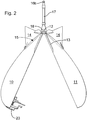
- the dispenser comprises a teardrop-shaped container comprising two container halves 10, 11 attached one to the other at a proximal or rear end by a hinge 12 formed on stabiliser fin halves 13 and mating to define a bait containing hollow.
- Each container half 10, 11 carries further stabiliser fins 14, transverse to the fins 13.
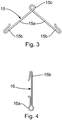
- a spring 15 is fitted at the rear end of the container, formed to urge open the container halves 10, 11. As shown in figure 3 the spring 15 comprises two arms 15a hooked at their outer ends 15b to engage the container halves 10, 11, and coiled at the inner end to form an attachment ring 15c.
- the line attachment bar 16 illustrated in figure 4 has a spring engagement hook 16a at its forward end and a line engagement hook 16b at its rear end.
- Rubber sheath members 17, 18 sheath the spring attachment ring 15c and the bar 16, the sheath member 17 being deformable to expose the hook 16b for attachment to a line and upon release to cover the attachment to the line thus retaining the attachment.
- the trailing edge of the fins 14 each carry a stop member 19 formed to abut the sheath 18 upon the container opening and thus impede opening beyond about 100°.
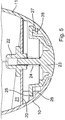
- the body half 10 carries a bulkhead 20 reinforced by brackets 21 and upon which is centrally mounted a plunger holder 22.
- the plunger holder 22 carries a plunger 23 arranged to be urged forward by a spring 24.
- the plunger 23 has a flange 25 which is arranged to pivot on a shoulder 26 on the container half 10 and a latch 27 arranged for engagement with a detent 28 formed on the container half 11.
- the distal, bow or lead end of the two container halves 10, 11 are formed with a mouth to which the plunger 23 forms a continuum.
- the body half 11 of the open bait dispenser is heaped with bait and the two body halves 10, 11 are then snapped shut. That is to say, the hinge 12 is closed against the force of the spring 15 and the latch 27 engaged on the detent 28 to hold the dispenser closed. If not already attached the dispenser is attached to a fishing line via the line link 16b, the sheath 17 having been pushed forward at the rear end thereof.
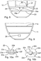
- the plunger holder 22 comprises a flange 22a which abuts the bulkhead 20, a hollow plunger shaft receiving boss 22b and finger grips 22c.
- the flange 22a has two opposing flat edges 22d and two rounded opposing edges 22e.
- One of the rounded edges 22e carries two stops 22f constructed to impede unwanted rotation of the plunger holder 22.
- Figure 8 shows the arrangement by which the plunger holder 22 is detachably held to the bulkhead 20.
- the brackets 21 carry flanges 80 under which the rounded edges 22e of the plunger holder 22 can be captured, but not the flat edges 22d.
- turning the plunger holder 22 alternately captures and releases the plunger holder 22.
- the release of the plunger holder 22 frees both the spring 24 and the plunger 23 from the body half 10.
- the arms of the plunger 23 differ one with respect to the other.
- the flange 25 comprises two teeth with a valley 25a between whilst the latch 27 comprises a single tooth.
- Figure 8 shows a protruberence 26a from the shoulder 26 for receiving the valley 25a and guides 20a depending from the bulkhead 20 for receiving the appropriate arm of the plunger 23
- the forward face of the plunger 23 has a cruciform indentation 23a by which the plunger may be rotated by the user. It will be appreciated that the angles of the face of the latch 27 and the detent 28, and the areas and textures thereof will have been determined, in consort with the spring stiffness etc., such that the required sensitivity of the release mechanism can be obtained.
- Figure 9 shows the location of the detent 28 in the body half 11. It also shows a bracket 11 a (also shown in figure 1 ), which serves to maintain the shape of the dispenser half 11 and also to impede access by bait to the working parts of the dispenser.
- Figures 11a, 11b illustrate an alternative construction in the embodiment described with reference to figures 1 to 6 and 8 - 10 , namely two different detents 28 and 28a, each set at a slightly different angle around the dispenser axis.
- the detent 28 is for opening the dispenser upon impact during use.
- the detent 28a which may be alternatively engaged by the plunger latch 27 following turning the plunger 23 through a few degrees, serves to maintain the dispenser closed during transportation.
- Figure 7 illustrates an alternative dispenser, constructed to act as a float and to remain associated with a definitive baited fishing line 70. Parts similar to those illustrated in the other figures have similar reference numbers.
- the two halves 10, 11 have flotation chambers 71 at the top end thereof and the relatively rigid link arm between the halves 10, 11 is a float 72.
- the line 70 carries two stops, one (70a) of which is downstream of the eye 16b and the other (70b) is upstream thereof.
- the stop 70a abuts the eye 16b during casting and the stop 70b abuts the eye 16b after hook deployment.
- the eye 16b may in this embodiment, if it is not desired for it to be hooked and associated with a retractable rubber sheath, be formed as a spring. This embodiment is particularly useful when employing a bait which might easily detach from the line during deployment. In that circumstance the hooked part of the line may be stowed in the dispenser during casting.
- the float 72 may for this embodiment be constructed, for example moulded in one piece, of a buoyant plastics material.
- the line attachment eye 16b may not be at the outer tip of the float 72 but intermediate its length or even at the base thereof.
- the bait dispenser of the embodiments described above is 17cm long and 6.5cm maximum breadth. Accordingly figure 1 shows the dispenser approximately full size, with the line attachment arm approximately 6.5cm long.
- This bait dispenser is moulded in polypropylene, the plunger is formed of acetal and the spring 15 and the arm 17 are formed of spring steel.
- Another embodiment is about 11 cm long and 4cm broad.
- the dispenser does not have a plunger and the catch member and its associated spring and detent are arranged to open upon sensing the shock wave generated by impact of the dispenser upon the water. In other words it may then not be necessary for the dispenser to land nose first on the water for a so-called vibration trip to open it.
- a latch 27 depth of 1.5mm will generally require the use of a plunger 23.
- a latch 27 depth of 1 mm coupled with a spring 24 of force 1.0 Newton will permit the dispenser to open on a vibration trip basis.
- a dispenser employing vibration trip to open may well be constructed with the catch/detent at the rear thereof and have no plunger etc at the bow end. Such a construction may have improved evacuation of the bait from the dispenser.
- Any of the embodiments above described may incorporate a filler hatch wherethrough bait may be loaded with the container parts closed.
- the hatch may be closed by a sliding or hinged door.
Landscapes
- Life Sciences & Earth Sciences (AREA)
- Environmental Sciences (AREA)
- Animal Husbandry (AREA)
- Biodiversity & Conservation Biology (AREA)
Applications Claiming Priority (2)
| Application Number | Priority Date | Filing Date | Title |
|---|---|---|---|
| GBGB0922366.0A GB0922366D0 (en) | 2009-12-22 | 2009-12-22 | Bait dispenser |
| PCT/GB2010/052054 WO2011077111A1 (en) | 2009-12-22 | 2010-12-09 | Bait dispenser |
Publications (2)
| Publication Number | Publication Date |
|---|---|
| EP2515638A1 EP2515638A1 (en) | 2012-10-31 |
| EP2515638B1 true EP2515638B1 (en) | 2017-03-01 |
Family
ID=41717356
Family Applications (1)
| Application Number | Title | Priority Date | Filing Date |
|---|---|---|---|
| EP10793028.1A Active EP2515638B1 (en) | 2009-12-22 | 2010-12-09 | Bait dispenser |
Country Status (8)
| Country | Link |
|---|---|
| US (1) | US20120317867A1 (enExample) |
| EP (1) | EP2515638B1 (enExample) |
| JP (1) | JP5799026B2 (enExample) |
| CN (1) | CN102753016A (enExample) |
| GB (1) | GB0922366D0 (enExample) |
| UA (1) | UA107207C2 (enExample) |
| WO (1) | WO2011077111A1 (enExample) |
| ZA (1) | ZA201204669B (enExample) |
Cited By (1)
| Publication number | Priority date | Publication date | Assignee | Title |
|---|---|---|---|---|
| RU179401U1 (ru) * | 2017-10-20 | 2018-05-14 | Сергей Анатольевич Шабашов | Разбрасыватель приманки |
Families Citing this family (18)
| Publication number | Priority date | Publication date | Assignee | Title |
|---|---|---|---|---|
| CA2737320C (en) * | 2011-04-14 | 2017-02-21 | Clare Machine Works Ltd. | Device for timed release of bait |
| GB201200969D0 (en) * | 2012-01-20 | 2012-03-07 | Houghton Bryan G | Bait dispenser |
| GB201206304D0 (en) | 2012-04-10 | 2012-05-23 | Houghton Bryan G | Bait dispenser |
| US9340337B2 (en) | 2012-05-01 | 2016-05-17 | Ecolab Usa Inc. | Dispenser with lockable pushbutton |
| US8851331B2 (en) | 2012-05-04 | 2014-10-07 | Ecolab Usa Inc. | Fluid dispensers with adjustable dosing |
| US20130337721A1 (en) * | 2012-06-14 | 2013-12-19 | Javier Guzman | Reusable pinata with spring loaded latches |
| US8991655B2 (en) | 2013-02-15 | 2015-03-31 | Ecolab Usa Inc. | Fluid dispensers with increased mechanical advantage |
| ITCR20130030A1 (it) * | 2013-12-11 | 2015-06-12 | Fg Devab Srl | Arnese di pasturazione utilizzabile in una battuta di pesca |
| JP2015198609A (ja) * | 2014-04-08 | 2015-11-12 | 株式会社シマノ | 釣用集寄 |
| CN106804550B (zh) * | 2015-11-29 | 2020-10-02 | 界首市欧思润体育用品有限公司 | 投放杆 |
| GB2551197B (en) * | 2016-06-10 | 2019-03-13 | Acergy France SAS | Controlling the buoyancy of a mass of buoyant spheres |
| CN106212406B (zh) * | 2016-09-24 | 2022-12-02 | 威海奥美仿生医疗装备科技有限公司 | 逆驱动路亚 |
| GB201704927D0 (en) * | 2017-03-28 | 2017-05-10 | Bvg Group Ltd | Fish bait dispenser |
| GB201709205D0 (en) | 2017-06-09 | 2017-07-26 | Spomb Fishing Ltd | Bait dispenser |
| US10798925B1 (en) * | 2019-10-04 | 2020-10-13 | Roger Llamas Booc | Magnetic bait-release device |
| US11744413B2 (en) | 2021-10-07 | 2023-09-05 | Deb Ip Limited | Dispenser assembly |
| JP7148834B1 (ja) * | 2022-06-16 | 2022-10-06 | 有限会社サニー商事 | こませかご及びロック解除方法 |
| GB202302088D0 (en) * | 2023-02-14 | 2023-03-29 | Wolf International Ltd | Device for dispensing bait |
Citations (1)
| Publication number | Priority date | Publication date | Assignee | Title |
|---|---|---|---|---|
| US3163957A (en) * | 1963-06-10 | 1965-01-05 | Barrett Orval | Bait casting device |
Family Cites Families (10)
| Publication number | Priority date | Publication date | Assignee | Title |
|---|---|---|---|---|
| JPS541430Y2 (enExample) * | 1976-06-03 | 1979-01-22 | ||
| JPS61158735A (ja) * | 1984-12-29 | 1986-07-18 | 小林 悟 | フカセ釣り方法及びフカセ釣り用釣り具 |
| JPH0728366U (ja) * | 1993-11-04 | 1995-05-30 | 由一 竹内 | 餌取り防止カプセル |
| JPH08131034A (ja) * | 1994-11-10 | 1996-05-28 | Naohiko Muto | 魚釣り用餌籠 |
| JP4266473B2 (ja) * | 2000-01-20 | 2009-05-20 | 株式会社シマノ | 撒き餌かご |
| JP2002315488A (ja) * | 2001-04-23 | 2002-10-29 | Kazuhiro Kitamura | 糸捲き付き反転撒餌器 |
| US20040068916A1 (en) * | 2002-10-15 | 2004-04-15 | Darrell Harris | Fish scent dispenser |
| JP3115244U (ja) * | 2005-05-12 | 2005-11-04 | 国男 本宮 | 餌撒きカップ |
| GB0801984D0 (en) * | 2008-02-04 | 2008-03-12 | Houghton Bryan G | Bait dispenser |
| CN201197325Y (zh) * | 2008-05-29 | 2009-02-25 | 孙波 | 双向翻转拉饵器 |
-
2009
- 2009-12-22 GB GBGB0922366.0A patent/GB0922366D0/en not_active Ceased
-
2010
- 2010-09-12 UA UAA201208258A patent/UA107207C2/ru unknown
- 2010-12-09 US US13/261,339 patent/US20120317867A1/en not_active Abandoned
- 2010-12-09 CN CN2010800633254A patent/CN102753016A/zh active Pending
- 2010-12-09 EP EP10793028.1A patent/EP2515638B1/en active Active
- 2010-12-09 JP JP2012545438A patent/JP5799026B2/ja active Active
- 2010-12-09 WO PCT/GB2010/052054 patent/WO2011077111A1/en not_active Ceased
-
2012
- 2012-06-22 ZA ZA2012/04669A patent/ZA201204669B/en unknown
Patent Citations (1)
| Publication number | Priority date | Publication date | Assignee | Title |
|---|---|---|---|---|
| US3163957A (en) * | 1963-06-10 | 1965-01-05 | Barrett Orval | Bait casting device |
Cited By (1)
| Publication number | Priority date | Publication date | Assignee | Title |
|---|---|---|---|---|
| RU179401U1 (ru) * | 2017-10-20 | 2018-05-14 | Сергей Анатольевич Шабашов | Разбрасыватель приманки |
Also Published As
| Publication number | Publication date |
|---|---|
| CN102753016A (zh) | 2012-10-24 |
| US20120317867A1 (en) | 2012-12-20 |
| GB0922366D0 (en) | 2010-02-03 |
| WO2011077111A1 (en) | 2011-06-30 |
| ZA201204669B (en) | 2013-09-25 |
| UA107207C2 (uk) | 2014-12-10 |
| JP2013514800A (ja) | 2013-05-02 |
| EP2515638A1 (en) | 2012-10-31 |
| JP5799026B2 (ja) | 2015-10-21 |
Similar Documents
| Publication | Publication Date | Title |
|---|---|---|
| EP2515638B1 (en) | Bait dispenser | |
| EP2244564B1 (en) | Device for casting ground bait | |
| WO2013153367A1 (en) | Bait dispenser | |
| US20160309691A1 (en) | Surface and subsurface dispenser for fish bait and fish food | |
| WO2013108012A1 (en) | Bait dispenser | |
| US20020078619A1 (en) | Tube Lure | |
| US8863339B2 (en) | Multipurpose tool | |
| WO2018224820A1 (en) | Bait dispenser | |
| US4821449A (en) | Sinker drop | |
| US5475944A (en) | Trot line reel with hook holders | |
| EP2893805B1 (en) | A fish-bait discharger | |
| WO2017005593A1 (en) | A device for use in sea fishing | |
| EP1800538B1 (en) | Swimfeeder | |
| WO2020178656A1 (en) | Tubular weight for throwing of fishing bait | |
| US20100011652A1 (en) | Self-Propelled Cast Fishing System | |
| ITPI20000031A1 (it) | Dispensatore di pastura per pescatori | |
| EP4373265B1 (en) | Bait dispenser and method of use thereof | |
| EP3911155B1 (en) | An angling device | |
| US4078424A (en) | Hand-held trolling speedometer | |
| GB2459167A (en) | Dispensing bait | |
| EP1256274A1 (en) | Spinning reel having instant switching apparatus for spool braking force | |
| GB1604903A (en) | Gravitational plastic bait dropper | |
| EP3522703A1 (en) | Bait dispenser |
Legal Events
| Date | Code | Title | Description |
|---|---|---|---|
| PUAI | Public reference made under article 153(3) epc to a published international application that has entered the european phase |
Free format text: ORIGINAL CODE: 0009012 |
|
| 17P | Request for examination filed |
Effective date: 20120702 |
|
| AK | Designated contracting states |
Kind code of ref document: A1 Designated state(s): AL AT BE BG CH CY CZ DE DK EE ES FI FR GB GR HR HU IE IS IT LI LT LU LV MC MK MT NL NO PL PT RO RS SE SI SK SM TR |
|
| DAX | Request for extension of the european patent (deleted) | ||
| 17Q | First examination report despatched |
Effective date: 20151021 |
|
| GRAP | Despatch of communication of intention to grant a patent |
Free format text: ORIGINAL CODE: EPIDOSNIGR1 |
|
| INTG | Intention to grant announced |
Effective date: 20160607 |
|
| GRAJ | Information related to disapproval of communication of intention to grant by the applicant or resumption of examination proceedings by the epo deleted |
Free format text: ORIGINAL CODE: EPIDOSDIGR1 |
|
| INTC | Intention to grant announced (deleted) | ||
| GRAP | Despatch of communication of intention to grant a patent |
Free format text: ORIGINAL CODE: EPIDOSNIGR1 |
|
| INTG | Intention to grant announced |
Effective date: 20160905 |
|
| GRAS | Grant fee paid |
Free format text: ORIGINAL CODE: EPIDOSNIGR3 |
|
| RAP1 | Party data changed (applicant data changed or rights of an application transferred) |
Owner name: SPOMB FISHING LIMITED |
|
| RIN1 | Information on inventor provided before grant (corrected) |
Inventor name: HOUGHTON, BRYAN GARY |
|
| GRAA | (expected) grant |
Free format text: ORIGINAL CODE: 0009210 |
|
| AK | Designated contracting states |
Kind code of ref document: B1 Designated state(s): AL AT BE BG CH CY CZ DE DK EE ES FI FR GB GR HR HU IE IS IT LI LT LU LV MC MK MT NL NO PL PT RO RS SE SI SK SM TR |
|
| REG | Reference to a national code |
Ref country code: GB Ref legal event code: FG4D |
|
| REG | Reference to a national code |
Ref country code: CH Ref legal event code: EP Ref country code: AT Ref legal event code: REF Ref document number: 870214 Country of ref document: AT Kind code of ref document: T Effective date: 20170315 |
|
| REG | Reference to a national code |
Ref country code: IE Ref legal event code: FG4D |
|
| REG | Reference to a national code |
Ref country code: DE Ref legal event code: R096 Ref document number: 602010040440 Country of ref document: DE |
|
| REG | Reference to a national code |
Ref country code: NL Ref legal event code: MP Effective date: 20170301 |
|
| REG | Reference to a national code |
Ref country code: LT Ref legal event code: MG4D |
|
| REG | Reference to a national code |
Ref country code: AT Ref legal event code: MK05 Ref document number: 870214 Country of ref document: AT Kind code of ref document: T Effective date: 20170301 |
|
| PG25 | Lapsed in a contracting state [announced via postgrant information from national office to epo] |
Ref country code: GR Free format text: LAPSE BECAUSE OF FAILURE TO SUBMIT A TRANSLATION OF THE DESCRIPTION OR TO PAY THE FEE WITHIN THE PRESCRIBED TIME-LIMIT Effective date: 20170602 Ref country code: HR Free format text: LAPSE BECAUSE OF FAILURE TO SUBMIT A TRANSLATION OF THE DESCRIPTION OR TO PAY THE FEE WITHIN THE PRESCRIBED TIME-LIMIT Effective date: 20170301 Ref country code: FI Free format text: LAPSE BECAUSE OF FAILURE TO SUBMIT A TRANSLATION OF THE DESCRIPTION OR TO PAY THE FEE WITHIN THE PRESCRIBED TIME-LIMIT Effective date: 20170301 Ref country code: NO Free format text: LAPSE BECAUSE OF FAILURE TO SUBMIT A TRANSLATION OF THE DESCRIPTION OR TO PAY THE FEE WITHIN THE PRESCRIBED TIME-LIMIT Effective date: 20170601 Ref country code: LT Free format text: LAPSE BECAUSE OF FAILURE TO SUBMIT A TRANSLATION OF THE DESCRIPTION OR TO PAY THE FEE WITHIN THE PRESCRIBED TIME-LIMIT Effective date: 20170301 |
|
| PG25 | Lapsed in a contracting state [announced via postgrant information from national office to epo] |
Ref country code: BG Free format text: LAPSE BECAUSE OF FAILURE TO SUBMIT A TRANSLATION OF THE DESCRIPTION OR TO PAY THE FEE WITHIN THE PRESCRIBED TIME-LIMIT Effective date: 20170601 Ref country code: AT Free format text: LAPSE BECAUSE OF FAILURE TO SUBMIT A TRANSLATION OF THE DESCRIPTION OR TO PAY THE FEE WITHIN THE PRESCRIBED TIME-LIMIT Effective date: 20170301 Ref country code: SE Free format text: LAPSE BECAUSE OF FAILURE TO SUBMIT A TRANSLATION OF THE DESCRIPTION OR TO PAY THE FEE WITHIN THE PRESCRIBED TIME-LIMIT Effective date: 20170301 Ref country code: LV Free format text: LAPSE BECAUSE OF FAILURE TO SUBMIT A TRANSLATION OF THE DESCRIPTION OR TO PAY THE FEE WITHIN THE PRESCRIBED TIME-LIMIT Effective date: 20170301 Ref country code: RS Free format text: LAPSE BECAUSE OF FAILURE TO SUBMIT A TRANSLATION OF THE DESCRIPTION OR TO PAY THE FEE WITHIN THE PRESCRIBED TIME-LIMIT Effective date: 20170301 Ref country code: ES Free format text: LAPSE BECAUSE OF FAILURE TO SUBMIT A TRANSLATION OF THE DESCRIPTION OR TO PAY THE FEE WITHIN THE PRESCRIBED TIME-LIMIT Effective date: 20170301 |
|
| PG25 | Lapsed in a contracting state [announced via postgrant information from national office to epo] |
Ref country code: NL Free format text: LAPSE BECAUSE OF FAILURE TO SUBMIT A TRANSLATION OF THE DESCRIPTION OR TO PAY THE FEE WITHIN THE PRESCRIBED TIME-LIMIT Effective date: 20170301 |
|
| REG | Reference to a national code |
Ref country code: FR Ref legal event code: PLFP Year of fee payment: 8 |
|
| PG25 | Lapsed in a contracting state [announced via postgrant information from national office to epo] |
Ref country code: SK Free format text: LAPSE BECAUSE OF FAILURE TO SUBMIT A TRANSLATION OF THE DESCRIPTION OR TO PAY THE FEE WITHIN THE PRESCRIBED TIME-LIMIT Effective date: 20170301 Ref country code: RO Free format text: LAPSE BECAUSE OF FAILURE TO SUBMIT A TRANSLATION OF THE DESCRIPTION OR TO PAY THE FEE WITHIN THE PRESCRIBED TIME-LIMIT Effective date: 20170301 Ref country code: EE Free format text: LAPSE BECAUSE OF FAILURE TO SUBMIT A TRANSLATION OF THE DESCRIPTION OR TO PAY THE FEE WITHIN THE PRESCRIBED TIME-LIMIT Effective date: 20170301 Ref country code: CZ Free format text: LAPSE BECAUSE OF FAILURE TO SUBMIT A TRANSLATION OF THE DESCRIPTION OR TO PAY THE FEE WITHIN THE PRESCRIBED TIME-LIMIT Effective date: 20170301 |
|
| PG25 | Lapsed in a contracting state [announced via postgrant information from national office to epo] |
Ref country code: PL Free format text: LAPSE BECAUSE OF FAILURE TO SUBMIT A TRANSLATION OF THE DESCRIPTION OR TO PAY THE FEE WITHIN THE PRESCRIBED TIME-LIMIT Effective date: 20170301 Ref country code: PT Free format text: LAPSE BECAUSE OF FAILURE TO SUBMIT A TRANSLATION OF THE DESCRIPTION OR TO PAY THE FEE WITHIN THE PRESCRIBED TIME-LIMIT Effective date: 20170703 Ref country code: SM Free format text: LAPSE BECAUSE OF FAILURE TO SUBMIT A TRANSLATION OF THE DESCRIPTION OR TO PAY THE FEE WITHIN THE PRESCRIBED TIME-LIMIT Effective date: 20170301 Ref country code: IS Free format text: LAPSE BECAUSE OF FAILURE TO SUBMIT A TRANSLATION OF THE DESCRIPTION OR TO PAY THE FEE WITHIN THE PRESCRIBED TIME-LIMIT Effective date: 20170701 |
|
| REG | Reference to a national code |
Ref country code: DE Ref legal event code: R097 Ref document number: 602010040440 Country of ref document: DE |
|
| PLBE | No opposition filed within time limit |
Free format text: ORIGINAL CODE: 0009261 |
|
| STAA | Information on the status of an ep patent application or granted ep patent |
Free format text: STATUS: NO OPPOSITION FILED WITHIN TIME LIMIT |
|
| PG25 | Lapsed in a contracting state [announced via postgrant information from national office to epo] |
Ref country code: DK Free format text: LAPSE BECAUSE OF FAILURE TO SUBMIT A TRANSLATION OF THE DESCRIPTION OR TO PAY THE FEE WITHIN THE PRESCRIBED TIME-LIMIT Effective date: 20170301 |
|
| 26N | No opposition filed |
Effective date: 20171204 |
|
| PG25 | Lapsed in a contracting state [announced via postgrant information from national office to epo] |
Ref country code: SI Free format text: LAPSE BECAUSE OF FAILURE TO SUBMIT A TRANSLATION OF THE DESCRIPTION OR TO PAY THE FEE WITHIN THE PRESCRIBED TIME-LIMIT Effective date: 20170301 |
|
| REG | Reference to a national code |
Ref country code: CH Ref legal event code: PL |
|
| REG | Reference to a national code |
Ref country code: IE Ref legal event code: MM4A |
|
| PG25 | Lapsed in a contracting state [announced via postgrant information from national office to epo] |
Ref country code: LU Free format text: LAPSE BECAUSE OF NON-PAYMENT OF DUE FEES Effective date: 20171209 Ref country code: MT Free format text: LAPSE BECAUSE OF NON-PAYMENT OF DUE FEES Effective date: 20171209 |
|
| REG | Reference to a national code |
Ref country code: BE Ref legal event code: MM Effective date: 20171231 |
|
| PG25 | Lapsed in a contracting state [announced via postgrant information from national office to epo] |
Ref country code: IE Free format text: LAPSE BECAUSE OF NON-PAYMENT OF DUE FEES Effective date: 20171209 |
|
| PG25 | Lapsed in a contracting state [announced via postgrant information from national office to epo] |
Ref country code: LI Free format text: LAPSE BECAUSE OF NON-PAYMENT OF DUE FEES Effective date: 20171231 Ref country code: CH Free format text: LAPSE BECAUSE OF NON-PAYMENT OF DUE FEES Effective date: 20171231 Ref country code: BE Free format text: LAPSE BECAUSE OF NON-PAYMENT OF DUE FEES Effective date: 20171231 |
|
| REG | Reference to a national code |
Ref country code: DE Ref legal event code: R082 Ref document number: 602010040440 Country of ref document: DE Representative=s name: LS-MP VON PUTTKAMER BERNGRUBER LOTH SPUHLER MU, DE Ref country code: DE Ref legal event code: R081 Ref document number: 602010040440 Country of ref document: DE Owner name: SPOMB FISHING LTD., WARLEY, GB Free format text: FORMER OWNER: SPOMB FISHING LTD., BROMLEY, GB |
|
| PG25 | Lapsed in a contracting state [announced via postgrant information from national office to epo] |
Ref country code: HU Free format text: LAPSE BECAUSE OF FAILURE TO SUBMIT A TRANSLATION OF THE DESCRIPTION OR TO PAY THE FEE WITHIN THE PRESCRIBED TIME-LIMIT; INVALID AB INITIO Effective date: 20101209 Ref country code: MC Free format text: LAPSE BECAUSE OF FAILURE TO SUBMIT A TRANSLATION OF THE DESCRIPTION OR TO PAY THE FEE WITHIN THE PRESCRIBED TIME-LIMIT Effective date: 20170301 |
|
| PG25 | Lapsed in a contracting state [announced via postgrant information from national office to epo] |
Ref country code: CY Free format text: LAPSE BECAUSE OF NON-PAYMENT OF DUE FEES Effective date: 20170301 |
|
| PG25 | Lapsed in a contracting state [announced via postgrant information from national office to epo] |
Ref country code: MK Free format text: LAPSE BECAUSE OF FAILURE TO SUBMIT A TRANSLATION OF THE DESCRIPTION OR TO PAY THE FEE WITHIN THE PRESCRIBED TIME-LIMIT Effective date: 20170301 |
|
| PG25 | Lapsed in a contracting state [announced via postgrant information from national office to epo] |
Ref country code: TR Free format text: LAPSE BECAUSE OF FAILURE TO SUBMIT A TRANSLATION OF THE DESCRIPTION OR TO PAY THE FEE WITHIN THE PRESCRIBED TIME-LIMIT Effective date: 20170301 |
|
| PG25 | Lapsed in a contracting state [announced via postgrant information from national office to epo] |
Ref country code: AL Free format text: LAPSE BECAUSE OF FAILURE TO SUBMIT A TRANSLATION OF THE DESCRIPTION OR TO PAY THE FEE WITHIN THE PRESCRIBED TIME-LIMIT Effective date: 20170301 |
|
| PGFP | Annual fee paid to national office [announced via postgrant information from national office to epo] |
Ref country code: DE Payment date: 20241220 Year of fee payment: 15 |
|
| PGFP | Annual fee paid to national office [announced via postgrant information from national office to epo] |
Ref country code: GB Payment date: 20241220 Year of fee payment: 15 |
|
| PGFP | Annual fee paid to national office [announced via postgrant information from national office to epo] |
Ref country code: FR Payment date: 20241230 Year of fee payment: 15 |
|
| PGFP | Annual fee paid to national office [announced via postgrant information from national office to epo] |
Ref country code: IT Payment date: 20241216 Year of fee payment: 15 |