EP2515529B1 - Operationseinheit, die eine Überwachungsvorrichtung umfasst, Anwendung einer solchen Operationseinheit und Operationsanlage - Google Patents
Operationseinheit, die eine Überwachungsvorrichtung umfasst, Anwendung einer solchen Operationseinheit und Operationsanlage Download PDFInfo
- Publication number
- EP2515529B1 EP2515529B1 EP12163941.3A EP12163941A EP2515529B1 EP 2515529 B1 EP2515529 B1 EP 2515529B1 EP 12163941 A EP12163941 A EP 12163941A EP 2515529 B1 EP2515529 B1 EP 2515529B1
- Authority
- EP
- European Patent Office
- Prior art keywords
- camera
- observation
- camera support
- operating
- assembly according
- Prior art date
- Legal status (The legal status is an assumption and is not a legal conclusion. Google has not performed a legal analysis and makes no representation as to the accuracy of the status listed.)
- Not-in-force
Links
- 238000012806 monitoring device Methods 0.000 title description 28
- 238000009434 installation Methods 0.000 description 6
- 230000007935 neutral effect Effects 0.000 description 6
- 238000006073 displacement reaction Methods 0.000 description 5
- 238000005286 illumination Methods 0.000 description 3
- 238000000034 method Methods 0.000 description 3
- 241000772415 Neovison vison Species 0.000 description 2
- 238000012544 monitoring process Methods 0.000 description 2
- 230000004075 alteration Effects 0.000 description 1
- 230000000712 assembly Effects 0.000 description 1
- 238000000429 assembly Methods 0.000 description 1
- 230000000694 effects Effects 0.000 description 1
- 238000007689 inspection Methods 0.000 description 1
- 230000003287 optical effect Effects 0.000 description 1
- 238000001356 surgical procedure Methods 0.000 description 1
Images
Classifications
-
- A—HUMAN NECESSITIES
- A61—MEDICAL OR VETERINARY SCIENCE; HYGIENE
- A61G—TRANSPORT, PERSONAL CONVEYANCES, OR ACCOMMODATION SPECIALLY ADAPTED FOR PATIENTS OR DISABLED PERSONS; OPERATING TABLES OR CHAIRS; CHAIRS FOR DENTISTRY; FUNERAL DEVICES
- A61G13/00—Operating tables; Auxiliary appliances therefor
- A61G13/10—Parts, details or accessories
-
- H—ELECTRICITY
- H04—ELECTRIC COMMUNICATION TECHNIQUE
- H04N—PICTORIAL COMMUNICATION, e.g. TELEVISION
- H04N23/00—Cameras or camera modules comprising electronic image sensors; Control thereof
- H04N23/90—Arrangement of cameras or camera modules, e.g. multiple cameras in TV studios or sports stadiums
-
- A—HUMAN NECESSITIES
- A61—MEDICAL OR VETERINARY SCIENCE; HYGIENE
- A61B—DIAGNOSIS; SURGERY; IDENTIFICATION
- A61B1/00—Instruments for performing medical examinations of the interior of cavities or tubes of the body by visual or photographical inspection, e.g. endoscopes; Illuminating arrangements therefor
- A61B1/04—Instruments for performing medical examinations of the interior of cavities or tubes of the body by visual or photographical inspection, e.g. endoscopes; Illuminating arrangements therefor combined with photographic or television appliances
Definitions
- the present invention relates to an operating assembly comprising a support extending along a central axis, an operative lighting device and a monitoring device, in particular of a medical operative field, the operative lighting device comprising an illumination support arm mounted on the support being movable in rotation with respect to an axis of rotation extending parallel to the central axis of the support, the monitoring device comprising a camera support arm mounted at a first end on the support being perpendicular to the central axis and movable in rotation relative to the support along an axis of rotation extending parallel to the central axis, the lighting support arm and the camera support arm being independent in rotational movement, the monitoring device further comprising a camera module comprising a camera mount mounted at the end of the camera support arm opposite to said first end and movable in rotation relative to the camera support arm along an axis of rotation extending parallel to the central axis, and drive means adapted to move the camera support relative to the support and control means of the training means.
- Operating assemblies comprising a device for monitoring a medical field of operation comprising a support and an arm movable relative to the support on which is disposed a camera intended to film the operating field.
- This camera is placed on an independent arm which must be handled by the medical team during the procedure.
- This type of known device therefore gives only limited access to remote viewers, and does not allow to give viewers a perfect view of the operating room in which is disposed this monitoring device.
- patent document is known WO 00/69354 an operating set as described above and intended to allow students to observe a remote operation through the monitoring device.
- this unique camera set offers limited remote viewing capabilities.
- Patent document is also known US 7224472 an operating assembly comprising a support, an operative lighting device and a monitoring device.
- this operating set intended to visualize in 3D markers, includes cameras mechanically linked to lighting so that the optical signals from the markers detected by the cameras can be evaluated in the shadowless area illuminated by the lighting device. As a result, this operating unit does not allow good remote observation.
- the object of the invention is to overcome at least one of these drawbacks and to propose an operating assembly with a monitoring device that allows good visibility of the operating field during the operation to a remote viewer.
- the monitoring device leads to low discomfort for the medical team during the procedure while being easy to handle.
- Another goal is that the operating set with monitoring device is economical.
- the subject of the invention is an operating assembly comprising a support extending along a central axis, an operating lighting device and a monitoring device, in particular of a surgical operating field, the operative lighting device.
- the operative lighting device comprising an illumination support arm mounted on the support being rotatable relative to an axis of rotation extending parallel to the central axis of the support
- the monitoring device comprising a camera support arm mounted at a first end on the support being perpendicular to the central axis and movable in rotation relative to the support along an axis of rotation extending parallel to the central axis, the lighting support arm and the camera support arm being independent in rotational movement
- the monitoring device further comprising a camera module comprising a camera mount mounted at the end of the camera support arm opposite the said first end and movable in rotation relative to the camera support arm along an axis of rotation extending parallel to the central axis, and means driving means adapted to move the camera support relative to the support and control means of the drive means, characterized in that the
- control means comprise a configuration in which each orientation device is controllable independently of one another by means of control means.
- the subject of the invention is also the use of an operating assembly according to the invention, in which the axes of vision of the surveillance cameras are parallel and the directions of vision are opposite to one another.
- the camera support arm occupies a fixed position.
- the subject of the invention is also the use of an operating assembly according to the invention, in which the device defines a median plane which extends perpendicularly to the plane passing through the two second axes of rotation and parallel to the two second axes of rotation. rotation and located midway between these two second axes of rotation, and the device comprises a configuration in which the two surveillance cameras set the same point of common interest, and the median plane passes through the point of common interest.
- the subject of the invention is also an operating installation comprising a medical operating room and an operating unit according to the invention, in which the surveillance cameras are installed in the operating theater, and in particular in which at least part of the means of command is outside the medical operating room in which the surveillance cameras are installed.
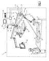
- the operating installation 2 comprises a medical operating room 4 and an operating assembly 6.
- the operating installation 2 also comprises a table d operation 8.
- a patient 10 On the operating table 8 is a patient 10 which defines a medical operation field 12. A surgeon 14 is in the vicinity of the patient 10 so as to intervene on the operating field 12.
- the operating unit 6 comprises a monitoring device 16 as well as a main operating light device 18.
- the operating unit 6 also comprises a display device 20 as well as a secondary operating light device 22.
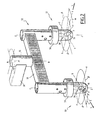
- the monitoring device 16 comprises a support 24 which is a post having an attachment end 26 and a free end 28.
- the support 24 extends along a central axis A-A.
- the fixing end 26 is fixed to a fixed structure, such as the ceiling of the medical operating room 4 or the wall of this operating room 4.
- the monitoring device 16 is provided with a camera support arm 30 and a camera module 32, which will be detailed later.
- the camera support arm 30 extends perpendicular to the support 24 or to the central axis AA.
- the camera support arm 30 is movable relative to the support 24, preferably in rotation about an axis of rotation extending parallel to the central axis AA of the support 24.
- the camera support arm 30 is preferably exclusively rotatable around this axis of rotation, that is to say that it has no other degrees of freedom of rotation with respect to the support 24.
- the mobile connection in rotation between the camera support arm 30 and the support 24 is carried out by means of a hinge 34.
- Suitable drive means 36 make it possible to move the camera support arm 30 relative to the support 24.
- These means of drive 36 are for example an electric motor.
- the main operative lighting device 18 and the secondary operative lighting device 22 each comprise an illumination support arm, 38 and 40 respectively, movable relative to the support 24, preferably in rotation about an axis of rotation. extending parallel to the central axis AA of the support 24 or coinciding with this central axis AA.
- the camera support arm 30 is disposed as close as possible to the fixing end 26, the lighting support arm 38 supporting the main operating light device 18 is disposed as close as possible to the free end 28, while the Lighting support 40 supporting the secondary operative lighting device 22 is arranged axially with respect to the central axis AA between the lighting support arm 38 and the camera support arm 30.
- the displacement of the lighting devices 18, 22 n is not bothered by the camera support arm 30.
- the monitoring device 16 comprises control means 42 adapted to control on the one hand the camera module 32 and on the other hand the displacement of the camera support arm 30 by driving the drive means 36.
- the control means 42 are offset from the support 24 and the camera support arm 30.
- the control means 42 comprise a control unit 44.
- the control unit 44 is connected to the drive means 36 and to the camera module 32 via control lines.
- the control means 42 also include a screen 46 which is adapted to display or display the image or the images captured by the camera module 32, as we will detail later.
- the screen 46 is disposed outside the operating room 4 in which the camera module 32 is installed.
- the control unit 44 is connected to the screen 46 by a link connection adapted to transmit the images.
- the control means 42 also comprise an input device 48, for example a keyboard, adapted to capture commands in order to control the camera module 32 and / or the displacement of the camera support arm 30.
- an input device 48 for example a keyboard
- the device of FIG. input 48 is disposed outside the operating room 4 in which the camera module 32 is installed.
- the control unit 44 is connected to the input device 48 by a connection adapted to transmit the commands entered via the input device to the control unit 44.
- the camera module 32 is disposed on one end of the camera support arm 30, said end being opposite to that providing the connection with the support 24.
- the camera module 32 comprises a camera support, in this case an arm 50 fixed at its center to the end of the camera support arm 30.
- Each free end of the arm 50 carries a viewing device respectively 52 and 53.
- the devices Mink 52 and 53 are identical, only one will be described later.
- Each vision device 52, 53 comprises a housing 54 fixed to one end of the arm 50, a surveillance camera 56 and an orientation device 58 adapted to move the surveillance camera 56 relative to the housing 54 and consequently with respect to the arm 50.
- the arm 50 is movable relative to the camera support arm 30, preferably in rotation about an axis BB extending parallel to the central axis AA of the support 24 and therefore perpendicularly to the camera support arm 30.
- the arm 50 is preferably exclusively mobile in rotation about this axis BB, that is to say it has no other degrees of freedom of rotation relative to the camera support arm 30.
- the mobile connection in rotation between the arm 50 and the camera support arm 30 is made by means of a hinge 55.
- a suitable drive motor allows the movement of the arm 50 relative to the camera support arm 30.
- the arm 50 is articulated about the axis BB in its current part, preferably halfway its ends.
- a neutral position of the arm 50 is defined, in which the arm 50 extends perpendicular to the camera support arm 30.
- the arm 50 is thus movable around an angular range ⁇ limited to + 90 ° / -90 ° around its position. neutral.
- Each surveillance camera 56 is disposed on either side of an axis of symmetry passing through the middle of the arm 50.
- Each surveillance camera 56 defines an axis of vision X-X and a direction of vision S which coincides with the axis of vision X-X.
- the orientation device 58 is adapted to orient the surveillance camera 56 according to a first axis of rotation Y-Y.
- the orientation device 58 comprises a drive motor along the Y-axis.
- the first axis of rotation Y-Y is arranged perpendicular to the axis of vision X-X.
- the orientation device 58 is also adapted to orient the surveillance camera along a second axis of rotation Z-Z, which is perpendicular to the first axis of rotation Y-Y and the axis of vision X-X.
- the orientation device 58 comprises a drive motor along the axis Z-Z.
- the X-X, Y-Y and Z-Z axes define a common point of intersection.
- the neutral position of the arm 50 or more generally of the camera support is defined by the position of the camera support, in which the plane passing through the two second axes of rotation ZZ belonging to the mink devices 52 and 53 extends perpendicularly. on the arm 30.
- the orientation device 58 defines a neutral position of the surveillance camera 56.
- the orientation device 58 is adapted to turn the surveillance camera about an angular range ⁇ limited to + 180 ° / -180 ° around the neutral position relative to the YY axis.
- the orientation device 58 is adapted to turn the surveillance camera around an angular range ⁇ limited to + 45 ° / -45 ° around the neutral position relative to the Z-Z axis.
- Each surveillance camera 56 has a viewing angle ⁇ of between 30 ° and 90 ° and preferably between 40 ° and 60 °. Also, the maximum zoom of the surveillance camera 56 indicated in focal length is between 3mm and 180mm and in particular between 3.4 mm and 120 mm.
- the surveillance camera 56 is an IP camera, that is to say a camera that is adapted to transmit data or the captured image via a protocol / TCP Internet connection.
- the surveillance camera 56 can be controlled by an IP / TCP link.
- the zoom of the surveillance camera 56 is adjustable and controllable.
- the drive motors along the Y-Y and Z-Z axes are preferably controllable by the IP / TCP link.
- the camera module 32 may include a microphone (not shown) adapted to capture the sound of the operating room.
- This microphone is preferably connected to the control means 42 and the control means 42 are adapted to transmit the sound picked up to a speaker.
- the control means can also transmit the sound via an IP / TCP link.
- the two surveillance cameras 56 each belonging to a vision device, respectively 52, 53, are used independently of one another and thus allow to the spectator disposed facing the screen 46 to observe two different points of view of the medical operating room 4.
- control means 42 are adapted to control the displacement of the camera support arm 30 and the displacement of the arm 50 supporting the vision devices 52, 53.
- the orientation and the zoom are controlled independently from one surveillance camera 56 to the other surveillance camera 56.
- a control input made by the input device 48 and associated with one of the surveillance cameras takes effect only for this camera, and does not cause a control of the other cameras.
- the screen 46 displays two independent images, each of which represents the image delivered respectively by one of the surveillance cameras 56. Two different points of view of the room can therefore be simultaneously monitored by the camera module 32.
- the viewer can best view the field of medical operation 12 according to two different points of view.
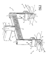
- the two surveillance cameras 56 each belonging to a vision device, respectively 52, 53 are oriented back-to-back so as to film each of the opposite parts of the room medical procedure 4.
- the X-X axes of vision of the two surveillance cameras 56 are parallel and the directions of vision are directed away from each other.
- the two X-X axes of vision coincide and lie in the plane passing through the two axes of rotation Z-Z.
- the position of the camera support arm 30 is fixed, that is to say once determined, the position of the camera support arm 30 is no longer modified.
- the orientation device 58 is no longer modified, which also means that the focal distance remains constant during the implementation of this second configuration.
- the surveillance cameras 56 are set to film opposite directions. For this purpose, once one of the surveillance cameras 56 is positioned, the control means 42 correctly position the other surveillance camera 56 in the desired position.
- control unit 44 has software adapted to virtually reconstitute the medical operating room 4 in three dimensions, from the images collected by the two surveillance cameras 56 and generate an image in two dimensions.
- the viewer can then evolve virtually in the operating room 4 without being physically present.
- the viewer With the input device, the viewer can move in the reconstituted medical operating room 4.
- the surveillance cameras 56 are used in "stereoscopic vision" mode.
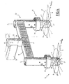
- the two surveillance cameras 56 fix a point of common interest, which may especially be the operating field 12 or part of this field.
- the surveillance cameras 56 In order to generate a stereoscopic image to the viewer, the surveillance cameras 56 must take a stereoscopic position with respect to the point of interest.
- the device defines a median plane PM extending perpendicular to a plane passing through the axes Z-Z, parallel to these two axes Z-Z and situated midway between these two axes Z-Z. In the stereoscopic position, the median plane PM passes through the common point of interest. This condition avoids aberrations in the restored stereoscopic image.
- the user defines using the input device 48 the point of interest to be observed.
- the control unit 44 then drives the camera support arm 30 and / or the arm 50 and / or the orientation device 58 of the surveillance cameras 56 so that they are positioned in the stereoscopic positioning as mentioned above. -above.
- the user can always control the zoom of the cameras in order to obtain the desired vision, near or hay, of this point of interest.
- the control unit 44 is adapted to synchronize the images received from each surveillance camera 56 so as to restore on the screen 46 a single stereoscopic image displaying the point of interest in relief.
- the control unit 44 is provided with stereoscopic software which is adapted to combine the images of the surveillance cameras simultaneously received.
- the stereoscopic image may be an anaglyph image, a polarized image, a time shift image, or any other stereoscopic image.
- the three modes of configuration and use can be used by a single monitoring device and implemented in a single monitoring device, the viewer selecting the configuration and the mode in which he wishes to use the monitoring device.
- the camera support 50 of the monitoring device according to the invention can be fixed directly on the support 24. In this case, it is preferably fixed in the vicinity of the free end 28 of this support 24. In this example embodiment, the monitoring device does not include the camera support arm Described above. The three modes of configuration and use described above can also be implemented by this variant.
- the camera support 50 is also rotatable relative to the support 24 and this preferably around the axis of rotation B-B which is parallel to the central axis A-A. More particularly, the axis of rotation B-B coincides with the central axis A-A.
- the mobility in rotation relative to the support is again obtained by a hinge 55.
- the monitoring device according to the invention is therefore suitable for inspection by a spectator of the remote medical operation field and for movement in an autonomous manner of the camera module 32 or the camera support arm 30 without the necessity of intervention of the surgical team, who can focus on the surgical procedure.
Landscapes
- Health & Medical Sciences (AREA)
- Engineering & Computer Science (AREA)
- Life Sciences & Earth Sciences (AREA)
- Multimedia (AREA)
- Signal Processing (AREA)
- Surgery (AREA)
- Biomedical Technology (AREA)
- Animal Behavior & Ethology (AREA)
- General Health & Medical Sciences (AREA)
- Public Health (AREA)
- Veterinary Medicine (AREA)
- Physics & Mathematics (AREA)
- Nuclear Medicine, Radiotherapy & Molecular Imaging (AREA)
- Optics & Photonics (AREA)
- Pathology (AREA)
- Radiology & Medical Imaging (AREA)
- Biophysics (AREA)
- Heart & Thoracic Surgery (AREA)
- Medical Informatics (AREA)
- Molecular Biology (AREA)
- Microscoopes, Condenser (AREA)
- Studio Devices (AREA)
- Accessories Of Cameras (AREA)
Claims (15)
- Operationseinheit, umfassend eine Stütze (24), die sich entlang einer Mittelachse (A-A) erstreckt, eine Operationsbeleuchtungsvorrichtung (18, 22) und eine Überwachungsvorrichtung (16), insbesondere eines medizinischen Operationsfeldes, wobei die Operationsbeleuchtungsvorrichtung (18, 22) einen Beleuchtungsstützarm (38, 40) umfasst, der auf der Stütze (24) montiert und drehbar in Bezug zu einer Drehachse beweglich ist, die sich parallel zur Mittelachse (A-A) der Stütze (24) erstreckt, wobei die Überwachungsvorrichtung (16) einen Kamerastützarm (30) umfasst, der an einem ersten Ende auf der Stütze (24) montiert ist, wobei er zur Mittelachse (A-A) senkrecht und drehbar in Bezug zur Stütze (24) entlang einer Drehachse, die sich parallel zur Mittelachse (A-A) erstreckt, beweglich ist, wobei der Beleuchtungsstützarm (38, 40) und der Kamerastützarm (30) in der Drehbewegung unabhängig sind, wobei die Überwachungsvorrichtung (16) ferner ein Kameramodul (32) aufweist, umfassend eine Kamerastütze (50), die am Ende des Kamerastützarms (30) gegenüber dem ersten Ende montiert und drehbar in Bezug zum Kamerastützarm (30) entlang einer Drehachse (B-B), die sich parallel zur Mittelachse (A-A) erstreckt, beweglich ist, und Antriebsmittel, die geeignet sind, die Kamerastütze (50) in Bezug zur Stütze (24) zu bewegen, und Steuermittel (42) für die Antriebsmittel, dadurch gekennzeichnet, dass das Kameramodul (32) zwei Überwachungskameras (56) umfasst, die jeweils eine Sichtachse (X-X) und eine Sichtrichtung (S) aufweisen, dass die Kamerastütze (50) ein Arm ist, der in seiner Mitte am Ende des Kamerastützarms (30) befestigt ist, und jedes freie Ende der Kamerastütze (50), eine Überwachungskamera (56) trägt, so dass die Überwachungskameras (56) beiderseits einer Symmetrieachse angeordnet sind, die durch die Mitte der Kamerastütze (50) verläuft.
- Operationseinheit nach Anspruch 1, dadurch gekennzeichnet, dass sie zwei Ausrichtungsvorrichtungen (58) umfasst, die von den Steuermitteln (42) gesteuert werden, wobei jede Vorrichtung dazu geeignet ist, eine der Überwachungskameras (56) gemäß mindestens einer ersten Drehachse (Y-Y) in Bezug zur Kamerastütze (50) auszurichten.
- Operationseinheit nach Anspruch 2, dadurch gekennzeichnet, dass jede Ausrichtungsvorrichtung (58) dazu geeignet ist, die zugehörige Überwachungskamera gemäß einer zweiten Drehachse (Z-Z) senkrecht auf die erste Drehachse (Y-Y) und die Sichtachse (X-X) auszurichten.
- Operationseinheit nach einem der vorhergehenden Ansprüche, dadurch gekennzeichnet, dass die Steuermittel (42) einen Bildschirm (46) umfassen, der dazu geeignet ist, das von mindestens einer der Überwachungskameras (56) und vorzugsweise von den beiden Überwachungskameras (56) aufgenommene Bild anzuzeigen.
- Operationseinheit nach einem der vorhergehenden Ansprüche, dadurch gekennzeichnet, dass die Überwachungseinheit (16) ferner Antriebsmittel umfasst, die von den Steuermitteln (42) gesteuert werden und dazu geeignet sind, den Kamerastützarm (30) in Bezug zur Stütze (24) und/oder die Kamerastütze (50) in Bezug zum Kamerastützarm (30) zu bewegen.
- Operationseinheit nach einem der vorhergehenden Ansprüche, dadurch gekennzeichnet, dass die Kamerastütze (50) in Bezug zum Kamerastützarm (30) in Drehung um die Achse (B-B) entlang eines gegebenen Winkelbereichs (µ) beweglich ist.
- Operationseinheit nach einem der vorhergehenden Ansprüche, dadurch gekennzeichnet, dass die Steuermittel (42) eine Steuereinheit (44) umfassen, die dazu geeignet ist, die von den beiden Überwachungskameras (56) aufgenommene Zone dreidimensional wiederzugeben.
- Operationseinheit nach Anspruch 7, dadurch gekennzeichnet, dass sie eine Ausführung umfasst, bei der die Sichtachsen (X-X) der Überwachungskameras (56) parallel sind und die Sichtrichtungen (S) zueinander entgegengesetzt sind.
- Operationseinheit nach einem der vorhergehenden Ansprüche, dadurch gekennzeichnet, dass die Steuermittel (42) eine Steuereinheit (44) umfassen, die dazu geeignet ist, die gleichzeitig von jeder Überwachungskamera (56) gesandten Bilder zu synchronisieren, um einem Betrachter ein Reliefbild zu liefern, wenn die beiden Überwachungskameras (56) einen selben Punkt von gemeinsamem Interesse fixieren.
- Operationseinheit nach Anspruch 3 und Anspruch 9, dadurch gekennzeichnet, dass die Überwachungsvorrichtung (16) eine Mittelebene (PM) definiert, die sich senkrecht auf die Ebene, die durch die beiden zweiten Drehachsen (Z-Z) verläuft, und parallel zu den beiden zweiten Drehachsen (Z-Z) erstreckt und auf halbem Abstand zwischen diesen beiden zweiten Drehachsen (Z-Z) angeordnet ist, und dass sie eine Ausführung umfasst, bei der die beiden Überwachungskameras (56) einen selben Punkt von gemeinsamem Interesse fixieren, und dass die Mittelebene durch den Punkt von gemeinsamem Interesse verläuft.
- Verwendung einer Operationseinheit nach Anspruch 2 in Kombination mit einem der vorhergehenden Ansprüche, bei der die Steuermittel (42) eine Ausführung umfassen, bei der jede Ausrichtungsvorrichtung (58) unabhängig von der anderen mit Hilfe der Steuermittel (42) steuerbar ist.
- Verwendung einer Operationseinheit nach den Ansprüchen 7 oder 8, bei der die Sichtachsen (X-X) der Überwachungskameras (56) parallel sind und die Sichtrichtungen (S) zueinander entgegengesetzt sind.
- Verwendung einer Operationseinheit nach Anspruch 12, bei der der Kamerastützarm (30) eine feste Position einnimmt.
- Verwendung einer Operationseinheit nach Anspruch 3 und einem der Ansprüche 9 oder 10, bei der die Vorrichtung eine Mittelebene (PM) definiert, die sich senkrecht auf die Ebene, die durch die beiden zweiten Drehachsen (Z-Z) verläuft, und parallel zu den beiden zweiten Drehachsen (Z-Z) erstreckt und auf halbem Abstand zwischen diesen zweiten Drehachsen (Z-Z) angeordnet ist, und bei der die Vorrichtung eine Ausführung umfasst, bei der die beiden Überwachungskameras (56) einen selben Punkt von gemeinsamem Interesse fixieren, wobei die Mittelebene durch den Punkt von gemeinsamem Interesse verläuft.
- Operationsanlage (2), umfassend einen medizinischen Operationssaal (4) und eine Operationseinheit nach mindestens einem der Ansprüche 1 bis 10, bei der die Überwachungskameras (56) in dem medizinischen Operationssaal (4) installiert sind, und insbesondere bei der sich mindestens ein Teil der Steuermittel (42) außerhalb des medizinischen Operationssaals (4) befindet, in dem die Überwachungskameras (56) installiert sind.
Applications Claiming Priority (1)
| Application Number | Priority Date | Filing Date | Title |
|---|---|---|---|
| FR1153393A FR2974473B1 (fr) | 2011-04-19 | 2011-04-19 | Dispositif de surveillance, utilisation d'un tel dispositif de surveillance et installation d'operation comprenant un tel dispositif de surveillance |
Publications (2)
| Publication Number | Publication Date |
|---|---|
| EP2515529A1 EP2515529A1 (de) | 2012-10-24 |
| EP2515529B1 true EP2515529B1 (de) | 2013-07-24 |
Family
ID=45929458
Family Applications (1)
| Application Number | Title | Priority Date | Filing Date |
|---|---|---|---|
| EP12163941.3A Not-in-force EP2515529B1 (de) | 2011-04-19 | 2012-04-12 | Operationseinheit, die eine Überwachungsvorrichtung umfasst, Anwendung einer solchen Operationseinheit und Operationsanlage |
Country Status (7)
| Country | Link |
|---|---|
| US (1) | US20120268565A1 (de) |
| EP (1) | EP2515529B1 (de) |
| JP (1) | JP5553854B2 (de) |
| KR (1) | KR101372864B1 (de) |
| CN (1) | CN102743227B (de) |
| FR (1) | FR2974473B1 (de) |
| TW (1) | TWI486146B (de) |
Families Citing this family (8)
| Publication number | Priority date | Publication date | Assignee | Title |
|---|---|---|---|---|
| US9987184B2 (en) * | 2013-02-05 | 2018-06-05 | Valentin Borovinov | Systems, methods, and media for providing video of a burial memorial |
| US9497380B1 (en) * | 2013-02-15 | 2016-11-15 | Red.Com, Inc. | Dense field imaging |
| WO2015001138A1 (es) * | 2013-07-02 | 2015-01-08 | Sociedad Española De Electromedicina Y Calidad, S.A. | Soporte telescópico plegable y portátil |
| FR3046828B1 (fr) | 2016-01-19 | 2019-09-20 | Maquet Sas | Dispositif de suspension medical a bras de deport |
| US10999493B2 (en) | 2017-12-22 | 2021-05-04 | Medtech S.A. | Scialytic light navigation |
| KR102052263B1 (ko) * | 2018-04-10 | 2019-12-05 | 가톨릭대학교 산학협력단 | 염증성 피부질환 중증도 진단을 위한 표준영상 데이터 취득용 촬영장치 |
| CN109528315B (zh) * | 2018-11-12 | 2021-12-17 | 南京迈瑞生物医疗电子有限公司 | 术野图像控制系统、方法、计算机设备及存储介质 |
| EP3927273B1 (de) | 2019-02-22 | 2023-01-04 | American Sterilizer Company | Montageplatte für ein aufhängungssystem für medizinprodukte |
Family Cites Families (13)
| Publication number | Priority date | Publication date | Assignee | Title |
|---|---|---|---|---|
| US6405072B1 (en) * | 1991-01-28 | 2002-06-11 | Sherwood Services Ag | Apparatus and method for determining a location of an anatomical target with reference to a medical apparatus |
| US5417210A (en) * | 1992-05-27 | 1995-05-23 | International Business Machines Corporation | System and method for augmentation of endoscopic surgery |
| GB9405299D0 (en) * | 1994-03-17 | 1994-04-27 | Roke Manor Research | Improvements in or relating to video-based systems for computer assisted surgery and localisation |
| US5622187A (en) * | 1994-09-30 | 1997-04-22 | Nomos Corporation | Method and apparatus for patient positioning for radiation therapy |
| CA2272040A1 (fr) * | 1999-05-13 | 2000-11-13 | Ecole Polytechnique | Systeme de camera d'observation robotisee pour utilisation en salle d'operation |
| CA2395377C (en) * | 1999-12-23 | 2008-02-19 | Hill-Rom Services, Inc. | Surgical theater system |
| EP1340470B1 (de) * | 2002-03-01 | 2004-09-15 | BrainLAB AG | Operationslampe mit Kamerasystem zur 3D-Referenzierung |
| FR2876175A1 (fr) * | 2004-10-01 | 2006-04-07 | Alm Sa | Support de distribution et systeme d'eclairage correspondant |
| WO2008017051A2 (en) * | 2006-08-02 | 2008-02-07 | Inneroptic Technology Inc. | System and method of providing real-time dynamic imagery of a medical procedure site using multiple modalities |
| US8357165B2 (en) * | 2006-12-22 | 2013-01-22 | Depuy Products, Inc. | Reference array mounting bracket for use with a computer assisted orthopaedic surgery system |
| US20090173846A1 (en) * | 2008-01-09 | 2009-07-09 | Allan Katz | Medical boom |
| DE102008055918A1 (de) | 2008-11-05 | 2010-05-06 | Siemens Aktiengesellschaft | Verfahren zum Betreiben eines medizinischen Navigationssystems und medizinisches Navigationssystem |
| CN100594009C (zh) * | 2008-12-26 | 2010-03-17 | 天津医科大学 | 自控激光手术设备 |
-
2011
- 2011-04-19 FR FR1153393A patent/FR2974473B1/fr not_active Expired - Fee Related
-
2012
- 2012-04-12 EP EP12163941.3A patent/EP2515529B1/de not_active Not-in-force
- 2012-04-16 JP JP2012092635A patent/JP5553854B2/ja not_active Expired - Fee Related
- 2012-04-18 CN CN201210125700.4A patent/CN102743227B/zh not_active Expired - Fee Related
- 2012-04-18 TW TW101113807A patent/TWI486146B/zh not_active IP Right Cessation
- 2012-04-19 KR KR1020120040704A patent/KR101372864B1/ko not_active Expired - Fee Related
- 2012-04-19 US US13/450,671 patent/US20120268565A1/en not_active Abandoned
Also Published As
| Publication number | Publication date |
|---|---|
| JP5553854B2 (ja) | 2014-07-16 |
| FR2974473A1 (fr) | 2012-10-26 |
| TWI486146B (zh) | 2015-06-01 |
| KR101372864B1 (ko) | 2014-03-10 |
| JP2012223581A (ja) | 2012-11-15 |
| CN102743227A (zh) | 2012-10-24 |
| FR2974473B1 (fr) | 2013-11-08 |
| US20120268565A1 (en) | 2012-10-25 |
| CN102743227B (zh) | 2014-05-28 |
| KR20120123218A (ko) | 2012-11-08 |
| EP2515529A1 (de) | 2012-10-24 |
| TW201249397A (en) | 2012-12-16 |
Similar Documents
| Publication | Publication Date | Title |
|---|---|---|
| EP2515529A1 (de) | Operationseinheit, die eine Überwachungsvorrichtung umfasst, Anwendung einer solchen Operationseinheit und Operationsanlage | |
| US6301447B1 (en) | Method and system for creation and interactive viewing of totally immersive stereoscopic images | |
| KR20210060529A (ko) | 팬케이크 렌즈 기반 디스플레이 어셈블리들의 능동 정렬 | |
| WO2004084542A1 (ja) | パノラマ画像生成方法及びその装置並びにこれらの方法・装置を用いた監視システム | |
| EP1870764A1 (de) | Optisches System zum Wechsel zwischen der Aufzeichnung einer Abbildung und der Projektion einer Abbildung | |
| ES2824049T3 (es) | Sistema y método para la monitorización remota de al menos un área de observación | |
| WO2018002674A1 (en) | Glasses for use in surgical procedures | |
| JP2001145640A (ja) | 被検体観察装置 | |
| EP1029415B1 (de) | Verfahren und system zur herstellung und anzeige von völlig inversiven stereoskopischen bildern | |
| FR3006418A1 (fr) | Studio mobile de prises de vues video | |
| JPH0993471A (ja) | パノラマ式テレビカメラ装置および映像モニタ装置 | |
| EP3008693A1 (de) | System zur positionsverfolgung einer bildaufnahmekamera für die aufnahme von videofilmen | |
| FR2838598A1 (fr) | Procede et dispositif de television stereoscopique | |
| WO2006093387A1 (en) | Panorama watch camera apparatus and the deferment unit thereof | |
| US11586106B2 (en) | Imaging apparatus having configurable stereoscopic perspective | |
| EP2867716B1 (de) | Vorrichtung zur überwachung der externen umgebung einer plattform, insbesondere einer meeresplattform, periskop und plattform mit solch einer vorrichtung | |
| EP0996283A1 (de) | Fernbedienungsvorrichtung für eine Kamera | |
| FR3070497B1 (fr) | Instrument d'imagerie pour controler une designation de cible | |
| FR3057430A1 (fr) | Dispositif d'immersion dans une representation d'un environnement resultant d'un ensemble d'images | |
| EP3423899A1 (de) | Steuerung einer bildaufnahmevorrichtung zur ermöglichung des vergleichs von zwei videos | |
| EP4390500A1 (de) | Bilderfassungssystem zur biometrischen iriserkennung einer person | |
| GB2436409A (en) | Camera with reflector for forming images on different sensor portions | |
| JP2006308846A (ja) | デジタルカメラ | |
| CA2943912C (fr) | Systeme de veille optronique a champ optique variable | |
| JP2017090630A (ja) | 旋回カメラ装置 |
Legal Events
| Date | Code | Title | Description |
|---|---|---|---|
| PUAI | Public reference made under article 153(3) epc to a published international application that has entered the european phase |
Free format text: ORIGINAL CODE: 0009012 |
|
| AK | Designated contracting states |
Kind code of ref document: A1 Designated state(s): AL AT BE BG CH CY CZ DE DK EE ES FI FR GB GR HR HU IE IS IT LI LT LU LV MC MK MT NL NO PL PT RO RS SE SI SK SM TR |
|
| AX | Request for extension of the european patent |
Extension state: BA ME |
|
| 17P | Request for examination filed |
Effective date: 20130219 |
|
| GRAP | Despatch of communication of intention to grant a patent |
Free format text: ORIGINAL CODE: EPIDOSNIGR1 |
|
| INTG | Intention to grant announced |
Effective date: 20130418 |
|
| GRAS | Grant fee paid |
Free format text: ORIGINAL CODE: EPIDOSNIGR3 |
|
| GRAA | (expected) grant |
Free format text: ORIGINAL CODE: 0009210 |
|
| AK | Designated contracting states |
Kind code of ref document: B1 Designated state(s): AL AT BE BG CH CY CZ DE DK EE ES FI FR GB GR HR HU IE IS IT LI LT LU LV MC MK MT NL NO PL PT RO RS SE SI SK SM TR |
|
| REG | Reference to a national code |
Ref country code: GB Ref legal event code: FG4D Free format text: NOT ENGLISH |
|
| REG | Reference to a national code |
Ref country code: CH Ref legal event code: EP |
|
| REG | Reference to a national code |
Ref country code: AT Ref legal event code: REF Ref document number: 623995 Country of ref document: AT Kind code of ref document: T Effective date: 20130815 |
|
| REG | Reference to a national code |
Ref country code: IE Ref legal event code: FG4D Free format text: LANGUAGE OF EP DOCUMENT: FRENCH |
|
| REG | Reference to a national code |
Ref country code: DE Ref legal event code: R096 Ref document number: 602012000154 Country of ref document: DE Effective date: 20130919 |
|
| REG | Reference to a national code |
Ref country code: AT Ref legal event code: MK05 Ref document number: 623995 Country of ref document: AT Kind code of ref document: T Effective date: 20130724 |
|
| REG | Reference to a national code |
Ref country code: NL Ref legal event code: VDEP Effective date: 20130724 |
|
| REG | Reference to a national code |
Ref country code: LT Ref legal event code: MG4D |
|
| PG25 | Lapsed in a contracting state [announced via postgrant information from national office to epo] |
Ref country code: AT Free format text: LAPSE BECAUSE OF FAILURE TO SUBMIT A TRANSLATION OF THE DESCRIPTION OR TO PAY THE FEE WITHIN THE PRESCRIBED TIME-LIMIT Effective date: 20130724 Ref country code: LT Free format text: LAPSE BECAUSE OF FAILURE TO SUBMIT A TRANSLATION OF THE DESCRIPTION OR TO PAY THE FEE WITHIN THE PRESCRIBED TIME-LIMIT Effective date: 20130724 Ref country code: IS Free format text: LAPSE BECAUSE OF FAILURE TO SUBMIT A TRANSLATION OF THE DESCRIPTION OR TO PAY THE FEE WITHIN THE PRESCRIBED TIME-LIMIT Effective date: 20131124 Ref country code: PT Free format text: LAPSE BECAUSE OF FAILURE TO SUBMIT A TRANSLATION OF THE DESCRIPTION OR TO PAY THE FEE WITHIN THE PRESCRIBED TIME-LIMIT Effective date: 20131125 Ref country code: NO Free format text: LAPSE BECAUSE OF FAILURE TO SUBMIT A TRANSLATION OF THE DESCRIPTION OR TO PAY THE FEE WITHIN THE PRESCRIBED TIME-LIMIT Effective date: 20131024 Ref country code: CY Free format text: LAPSE BECAUSE OF FAILURE TO SUBMIT A TRANSLATION OF THE DESCRIPTION OR TO PAY THE FEE WITHIN THE PRESCRIBED TIME-LIMIT Effective date: 20130918 Ref country code: HR Free format text: LAPSE BECAUSE OF FAILURE TO SUBMIT A TRANSLATION OF THE DESCRIPTION OR TO PAY THE FEE WITHIN THE PRESCRIBED TIME-LIMIT Effective date: 20130724 Ref country code: SE Free format text: LAPSE BECAUSE OF FAILURE TO SUBMIT A TRANSLATION OF THE DESCRIPTION OR TO PAY THE FEE WITHIN THE PRESCRIBED TIME-LIMIT Effective date: 20130724 |
|
| PG25 | Lapsed in a contracting state [announced via postgrant information from national office to epo] |
Ref country code: NL Free format text: LAPSE BECAUSE OF FAILURE TO SUBMIT A TRANSLATION OF THE DESCRIPTION OR TO PAY THE FEE WITHIN THE PRESCRIBED TIME-LIMIT Effective date: 20130724 Ref country code: SI Free format text: LAPSE BECAUSE OF FAILURE TO SUBMIT A TRANSLATION OF THE DESCRIPTION OR TO PAY THE FEE WITHIN THE PRESCRIBED TIME-LIMIT Effective date: 20130724 Ref country code: LV Free format text: LAPSE BECAUSE OF FAILURE TO SUBMIT A TRANSLATION OF THE DESCRIPTION OR TO PAY THE FEE WITHIN THE PRESCRIBED TIME-LIMIT Effective date: 20130724 Ref country code: GR Free format text: LAPSE BECAUSE OF FAILURE TO SUBMIT A TRANSLATION OF THE DESCRIPTION OR TO PAY THE FEE WITHIN THE PRESCRIBED TIME-LIMIT Effective date: 20131025 Ref country code: FI Free format text: LAPSE BECAUSE OF FAILURE TO SUBMIT A TRANSLATION OF THE DESCRIPTION OR TO PAY THE FEE WITHIN THE PRESCRIBED TIME-LIMIT Effective date: 20130724 Ref country code: PL Free format text: LAPSE BECAUSE OF FAILURE TO SUBMIT A TRANSLATION OF THE DESCRIPTION OR TO PAY THE FEE WITHIN THE PRESCRIBED TIME-LIMIT Effective date: 20130724 |
|
| PG25 | Lapsed in a contracting state [announced via postgrant information from national office to epo] |
Ref country code: CY Free format text: LAPSE BECAUSE OF FAILURE TO SUBMIT A TRANSLATION OF THE DESCRIPTION OR TO PAY THE FEE WITHIN THE PRESCRIBED TIME-LIMIT Effective date: 20130724 |
|
| PG25 | Lapsed in a contracting state [announced via postgrant information from national office to epo] |
Ref country code: EE Free format text: LAPSE BECAUSE OF FAILURE TO SUBMIT A TRANSLATION OF THE DESCRIPTION OR TO PAY THE FEE WITHIN THE PRESCRIBED TIME-LIMIT Effective date: 20130724 Ref country code: RO Free format text: LAPSE BECAUSE OF FAILURE TO SUBMIT A TRANSLATION OF THE DESCRIPTION OR TO PAY THE FEE WITHIN THE PRESCRIBED TIME-LIMIT Effective date: 20130724 Ref country code: CZ Free format text: LAPSE BECAUSE OF FAILURE TO SUBMIT A TRANSLATION OF THE DESCRIPTION OR TO PAY THE FEE WITHIN THE PRESCRIBED TIME-LIMIT Effective date: 20130724 Ref country code: DK Free format text: LAPSE BECAUSE OF FAILURE TO SUBMIT A TRANSLATION OF THE DESCRIPTION OR TO PAY THE FEE WITHIN THE PRESCRIBED TIME-LIMIT Effective date: 20130724 Ref country code: SK Free format text: LAPSE BECAUSE OF FAILURE TO SUBMIT A TRANSLATION OF THE DESCRIPTION OR TO PAY THE FEE WITHIN THE PRESCRIBED TIME-LIMIT Effective date: 20130724 |
|
| PG25 | Lapsed in a contracting state [announced via postgrant information from national office to epo] |
Ref country code: ES Free format text: LAPSE BECAUSE OF FAILURE TO SUBMIT A TRANSLATION OF THE DESCRIPTION OR TO PAY THE FEE WITHIN THE PRESCRIBED TIME-LIMIT Effective date: 20130724 |
|
| PLBE | No opposition filed within time limit |
Free format text: ORIGINAL CODE: 0009261 |
|
| STAA | Information on the status of an ep patent application or granted ep patent |
Free format text: STATUS: NO OPPOSITION FILED WITHIN TIME LIMIT |
|
| 26N | No opposition filed |
Effective date: 20140425 |
|
| REG | Reference to a national code |
Ref country code: DE Ref legal event code: R097 Ref document number: 602012000154 Country of ref document: DE Effective date: 20140425 |
|
| PG25 | Lapsed in a contracting state [announced via postgrant information from national office to epo] |
Ref country code: MC Free format text: LAPSE BECAUSE OF FAILURE TO SUBMIT A TRANSLATION OF THE DESCRIPTION OR TO PAY THE FEE WITHIN THE PRESCRIBED TIME-LIMIT Effective date: 20130724 Ref country code: LU Free format text: LAPSE BECAUSE OF FAILURE TO SUBMIT A TRANSLATION OF THE DESCRIPTION OR TO PAY THE FEE WITHIN THE PRESCRIBED TIME-LIMIT Effective date: 20140412 |
|
| REG | Reference to a national code |
Ref country code: IE Ref legal event code: MM4A |
|
| REG | Reference to a national code |
Ref country code: FR Ref legal event code: PLFP Year of fee payment: 4 |
|
| PG25 | Lapsed in a contracting state [announced via postgrant information from national office to epo] |
Ref country code: IE Free format text: LAPSE BECAUSE OF NON-PAYMENT OF DUE FEES Effective date: 20140412 |
|
| PGFP | Annual fee paid to national office [announced via postgrant information from national office to epo] |
Ref country code: DE Payment date: 20150421 Year of fee payment: 4 |
|
| PGFP | Annual fee paid to national office [announced via postgrant information from national office to epo] |
Ref country code: IT Payment date: 20150430 Year of fee payment: 4 Ref country code: FR Payment date: 20150413 Year of fee payment: 4 Ref country code: BE Payment date: 20150420 Year of fee payment: 4 |
|
| REG | Reference to a national code |
Ref country code: CH Ref legal event code: PL |
|
| PG25 | Lapsed in a contracting state [announced via postgrant information from national office to epo] |
Ref country code: CH Free format text: LAPSE BECAUSE OF NON-PAYMENT OF DUE FEES Effective date: 20150430 Ref country code: LI Free format text: LAPSE BECAUSE OF NON-PAYMENT OF DUE FEES Effective date: 20150430 |
|
| PG25 | Lapsed in a contracting state [announced via postgrant information from national office to epo] |
Ref country code: MT Free format text: LAPSE BECAUSE OF FAILURE TO SUBMIT A TRANSLATION OF THE DESCRIPTION OR TO PAY THE FEE WITHIN THE PRESCRIBED TIME-LIMIT Effective date: 20130724 |
|
| PG25 | Lapsed in a contracting state [announced via postgrant information from national office to epo] |
Ref country code: SM Free format text: LAPSE BECAUSE OF FAILURE TO SUBMIT A TRANSLATION OF THE DESCRIPTION OR TO PAY THE FEE WITHIN THE PRESCRIBED TIME-LIMIT Effective date: 20130724 |
|
| PG25 | Lapsed in a contracting state [announced via postgrant information from national office to epo] |
Ref country code: BG Free format text: LAPSE BECAUSE OF FAILURE TO SUBMIT A TRANSLATION OF THE DESCRIPTION OR TO PAY THE FEE WITHIN THE PRESCRIBED TIME-LIMIT Effective date: 20130724 Ref country code: RS Free format text: LAPSE BECAUSE OF NON-PAYMENT OF DUE FEES Effective date: 20130724 |
|
| PG25 | Lapsed in a contracting state [announced via postgrant information from national office to epo] |
Ref country code: TR Free format text: LAPSE BECAUSE OF FAILURE TO SUBMIT A TRANSLATION OF THE DESCRIPTION OR TO PAY THE FEE WITHIN THE PRESCRIBED TIME-LIMIT Effective date: 20130724 Ref country code: HU Free format text: LAPSE BECAUSE OF FAILURE TO SUBMIT A TRANSLATION OF THE DESCRIPTION OR TO PAY THE FEE WITHIN THE PRESCRIBED TIME-LIMIT; INVALID AB INITIO Effective date: 20120412 |
|
| PG25 | Lapsed in a contracting state [announced via postgrant information from national office to epo] |
Ref country code: BE Free format text: LAPSE BECAUSE OF NON-PAYMENT OF DUE FEES Effective date: 20160430 |
|
| REG | Reference to a national code |
Ref country code: DE Ref legal event code: R119 Ref document number: 602012000154 Country of ref document: DE |
|
| GBPC | Gb: european patent ceased through non-payment of renewal fee |
Effective date: 20160412 |
|
| REG | Reference to a national code |
Ref country code: FR Ref legal event code: ST Effective date: 20161230 |
|
| PG25 | Lapsed in a contracting state [announced via postgrant information from national office to epo] |
Ref country code: GB Free format text: LAPSE BECAUSE OF NON-PAYMENT OF DUE FEES Effective date: 20160412 Ref country code: DE Free format text: LAPSE BECAUSE OF NON-PAYMENT OF DUE FEES Effective date: 20161101 Ref country code: FR Free format text: LAPSE BECAUSE OF NON-PAYMENT OF DUE FEES Effective date: 20160502 |
|
| PG25 | Lapsed in a contracting state [announced via postgrant information from national office to epo] |
Ref country code: IT Free format text: LAPSE BECAUSE OF NON-PAYMENT OF DUE FEES Effective date: 20160412 |
|
| PG25 | Lapsed in a contracting state [announced via postgrant information from national office to epo] |
Ref country code: MK Free format text: LAPSE BECAUSE OF FAILURE TO SUBMIT A TRANSLATION OF THE DESCRIPTION OR TO PAY THE FEE WITHIN THE PRESCRIBED TIME-LIMIT Effective date: 20130724 |
|
| PG25 | Lapsed in a contracting state [announced via postgrant information from national office to epo] |
Ref country code: AL Free format text: LAPSE BECAUSE OF FAILURE TO SUBMIT A TRANSLATION OF THE DESCRIPTION OR TO PAY THE FEE WITHIN THE PRESCRIBED TIME-LIMIT Effective date: 20130724 |