EP2515418A2 - Motorhalterung mit adaptativen Entkopplungsmitteln - Google Patents
Motorhalterung mit adaptativen Entkopplungsmitteln Download PDFInfo
- Publication number
- EP2515418A2 EP2515418A2 EP12002661A EP12002661A EP2515418A2 EP 2515418 A2 EP2515418 A2 EP 2515418A2 EP 12002661 A EP12002661 A EP 12002661A EP 12002661 A EP12002661 A EP 12002661A EP 2515418 A2 EP2515418 A2 EP 2515418A2
- Authority
- EP
- European Patent Office
- Prior art keywords
- decoupling means
- decoupling
- motor
- adaptive device
- adaptive
- Prior art date
- Legal status (The legal status is an assumption and is not a legal conclusion. Google has not performed a legal analysis and makes no representation as to the accuracy of the status listed.)
- Withdrawn
Links
- 230000003044 adaptive effect Effects 0.000 title claims abstract description 64
- 238000010438 heat treatment Methods 0.000 claims abstract description 36
- 239000000463 material Substances 0.000 claims description 13
- 239000000470 constituent Substances 0.000 claims description 3
- 238000009423 ventilation Methods 0.000 description 27
- 238000004378 air conditioning Methods 0.000 description 25
- 230000002093 peripheral effect Effects 0.000 description 12
- 238000013016 damping Methods 0.000 description 11
- 230000035882 stress Effects 0.000 description 9
- 230000001133 acceleration Effects 0.000 description 8
- 230000033001 locomotion Effects 0.000 description 7
- 230000004048 modification Effects 0.000 description 7
- 238000012986 modification Methods 0.000 description 7
- 230000006355 external stress Effects 0.000 description 6
- 230000006978 adaptation Effects 0.000 description 5
- 230000008901 benefit Effects 0.000 description 4
- 238000009434 installation Methods 0.000 description 4
- 238000003032 molecular docking Methods 0.000 description 4
- 230000005540 biological transmission Effects 0.000 description 3
- 238000001816 cooling Methods 0.000 description 3
- 229920001971 elastomer Polymers 0.000 description 3
- 239000004033 plastic Substances 0.000 description 3
- 238000011144 upstream manufacturing Methods 0.000 description 3
- 230000009471 action Effects 0.000 description 2
- 238000004026 adhesive bonding Methods 0.000 description 2
- 230000003321 amplification Effects 0.000 description 2
- 238000004364 calculation method Methods 0.000 description 2
- 230000005465 channeling Effects 0.000 description 2
- 230000000052 comparative effect Effects 0.000 description 2
- 239000004020 conductor Substances 0.000 description 2
- 239000000806 elastomer Substances 0.000 description 2
- 238000002955 isolation Methods 0.000 description 2
- 238000003199 nucleic acid amplification method Methods 0.000 description 2
- 230000005693 optoelectronics Effects 0.000 description 2
- 238000005096 rolling process Methods 0.000 description 2
- 229920002943 EPDM rubber Polymers 0.000 description 1
- 239000004743 Polypropylene Substances 0.000 description 1
- 230000004913 activation Effects 0.000 description 1
- 230000000903 blocking effect Effects 0.000 description 1
- 230000008859 change Effects 0.000 description 1
- 230000000295 complement effect Effects 0.000 description 1
- 230000000694 effects Effects 0.000 description 1
- 235000021183 entrée Nutrition 0.000 description 1
- 235000019589 hardness Nutrition 0.000 description 1
- 229920000642 polymer Polymers 0.000 description 1
- -1 polypropylene Polymers 0.000 description 1
- 229920001155 polypropylene Polymers 0.000 description 1
- 230000002787 reinforcement Effects 0.000 description 1
- 230000035939 shock Effects 0.000 description 1
- 229920001935 styrene-ethylene-butadiene-styrene Polymers 0.000 description 1
- 230000009466 transformation Effects 0.000 description 1
Images
Classifications
-
- H—ELECTRICITY
- H02—GENERATION; CONVERSION OR DISTRIBUTION OF ELECTRIC POWER
- H02K—DYNAMO-ELECTRIC MACHINES
- H02K5/00—Casings; Enclosures; Supports
- H02K5/24—Casings; Enclosures; Supports specially adapted for suppression or reduction of noise or vibrations
-
- B—PERFORMING OPERATIONS; TRANSPORTING
- B60—VEHICLES IN GENERAL
- B60H—ARRANGEMENTS OF HEATING, COOLING, VENTILATING OR OTHER AIR-TREATING DEVICES SPECIALLY ADAPTED FOR PASSENGER OR GOODS SPACES OF VEHICLES
- B60H1/00—Heating, cooling or ventilating [HVAC] devices
- B60H1/00457—Ventilation unit, e.g. combined with a radiator
-
- F—MECHANICAL ENGINEERING; LIGHTING; HEATING; WEAPONS; BLASTING
- F04—POSITIVE - DISPLACEMENT MACHINES FOR LIQUIDS; PUMPS FOR LIQUIDS OR ELASTIC FLUIDS
- F04D—NON-POSITIVE-DISPLACEMENT PUMPS
- F04D25/00—Pumping installations or systems
- F04D25/02—Units comprising pumps and their driving means
- F04D25/08—Units comprising pumps and their driving means the working fluid being air, e.g. for ventilation
-
- F—MECHANICAL ENGINEERING; LIGHTING; HEATING; WEAPONS; BLASTING
- F04—POSITIVE - DISPLACEMENT MACHINES FOR LIQUIDS; PUMPS FOR LIQUIDS OR ELASTIC FLUIDS
- F04D—NON-POSITIVE-DISPLACEMENT PUMPS
- F04D27/00—Control, e.g. regulation, of pumps, pumping installations or pumping systems specially adapted for elastic fluids
-
- F—MECHANICAL ENGINEERING; LIGHTING; HEATING; WEAPONS; BLASTING
- F04—POSITIVE - DISPLACEMENT MACHINES FOR LIQUIDS; PUMPS FOR LIQUIDS OR ELASTIC FLUIDS
- F04D—NON-POSITIVE-DISPLACEMENT PUMPS
- F04D29/00—Details, component parts, or accessories
- F04D29/66—Combating cavitation, whirls, noise, vibration or the like; Balancing
- F04D29/661—Combating cavitation, whirls, noise, vibration or the like; Balancing especially adapted for elastic fluid pumps
- F04D29/668—Combating cavitation, whirls, noise, vibration or the like; Balancing especially adapted for elastic fluid pumps damping or preventing mechanical vibrations
-
- F—MECHANICAL ENGINEERING; LIGHTING; HEATING; WEAPONS; BLASTING
- F16—ENGINEERING ELEMENTS AND UNITS; GENERAL MEASURES FOR PRODUCING AND MAINTAINING EFFECTIVE FUNCTIONING OF MACHINES OR INSTALLATIONS; THERMAL INSULATION IN GENERAL
- F16F—SPRINGS; SHOCK-ABSORBERS; MEANS FOR DAMPING VIBRATION
- F16F1/00—Springs
- F16F1/36—Springs made of rubber or other material having high internal friction, e.g. thermoplastic elastomers
- F16F1/3615—Springs made of rubber or other material having high internal friction, e.g. thermoplastic elastomers with means for modifying the spring characteristic
-
- F—MECHANICAL ENGINEERING; LIGHTING; HEATING; WEAPONS; BLASTING
- F16—ENGINEERING ELEMENTS AND UNITS; GENERAL MEASURES FOR PRODUCING AND MAINTAINING EFFECTIVE FUNCTIONING OF MACHINES OR INSTALLATIONS; THERMAL INSULATION IN GENERAL
- F16F—SPRINGS; SHOCK-ABSORBERS; MEANS FOR DAMPING VIBRATION
- F16F15/00—Suppression of vibrations in systems; Means or arrangements for avoiding or reducing out-of-balance forces, e.g. due to motion
- F16F15/02—Suppression of vibrations of non-rotating, e.g. reciprocating systems; Suppression of vibrations of rotating systems by use of members not moving with the rotating systems
- F16F15/04—Suppression of vibrations of non-rotating, e.g. reciprocating systems; Suppression of vibrations of rotating systems by use of members not moving with the rotating systems using elastic means
- F16F15/08—Suppression of vibrations of non-rotating, e.g. reciprocating systems; Suppression of vibrations of rotating systems by use of members not moving with the rotating systems using elastic means with rubber springs ; with springs made of rubber and metal
-
- H—ELECTRICITY
- H02—GENERATION; CONVERSION OR DISTRIBUTION OF ELECTRIC POWER
- H02K—DYNAMO-ELECTRIC MACHINES
- H02K11/00—Structural association of dynamo-electric machines with electric components or with devices for shielding, monitoring or protection
- H02K11/0094—Structural association with other electrical or electronic devices
-
- B—PERFORMING OPERATIONS; TRANSPORTING
- B60—VEHICLES IN GENERAL
- B60H—ARRANGEMENTS OF HEATING, COOLING, VENTILATING OR OTHER AIR-TREATING DEVICES SPECIALLY ADAPTED FOR PASSENGER OR GOODS SPACES OF VEHICLES
- B60H1/00—Heating, cooling or ventilating [HVAC] devices
- B60H1/00507—Details, e.g. mounting arrangements, desaeration devices
- B60H2001/006—Noise reduction
-
- H—ELECTRICITY
- H02—GENERATION; CONVERSION OR DISTRIBUTION OF ELECTRIC POWER
- H02K—DYNAMO-ELECTRIC MACHINES
- H02K2213/00—Specific aspects, not otherwise provided for and not covered by codes H02K2201/00 - H02K2211/00
- H02K2213/09—Machines characterised by the presence of elements which are subject to variation, e.g. adjustable bearings, reconfigurable windings, variable pitch ventilators
Definitions
- the present invention relates to a motor support, in particular an electric motor support, in particular for ventilation installations, or heating, ventilation and / or air conditioning installations for a motor vehicle. More particularly, the invention relates to a motor support equipped with adaptive means for damping transmitted or transmitted vibrations.
- a heating, ventilation and / or air conditioning system for a motor vehicle
- the flow of circulating air is propelled by a motor-fan unit comprising in particular a blower wheel and an electric motor capable of rotating the blower wheel.
- the motor-fan unit also comprises a motor support, secured to a housing of the heating, ventilation and / or air conditioning system, a cavity is adapted to receive the motor of the motor-fan unit.
- the motor support conventionally consists of an outer ring and a receiving member of the electric motor.
- the receiving member is connected to the outer ring by decoupling means, acting as an internal vibration damper.
- decoupling means acting as an internal vibration damper.
- the housing of the heating, ventilation and / or air conditioning system, to which the engine support is connected is also subjected to vibrations caused by the movements of the vehicle.
- strong stresses and external stresses are transmitted to the electric motor mounted in the engine mount, through the housing of the heating, ventilation and / or air conditioning system.
- These external vibrations can cause damage to components of the heating, ventilation and / or air conditioning system, including the blower wheel.
- Such an increase in rigidity decoupling means for preventing the transmission of external stresses and stresses degrades the damping of the internal vibrations emitted by the electric motor.
- the decoupling means must also allow a good damping of internal vibrations in various frequency ranges due to the various modes and / or different operating speeds of the motor of the motor-fan unit.
- a specific rigidity must be defined to absorb the internal vibrations appearing in a given frequency range.
- the object of the present invention is therefore to solve the disadvantages described above, mainly by acting on the decoupling means to give it a defined stiffness, under certain conditions, for example when the vehicle is subjected to external stresses and stresses to the support- motor, while giving it an effective flexibility to prevent the propagation of vibrations internal to the engine support, especially in various frequency ranges.
- the invention therefore relates to a motor support comprising an outer ring and a receiving member of an electric motor.
- the receiving member is connected to the outer ring by decoupling means.
- the decoupling means comprise an adaptive device capable of modifying at least one mechanical characteristic of the decoupling means.
- the decoupling means are installed in a space between the outer ring and the receiving member, the outer ring and the receiving member not being in direct contact with each other. Only the decoupling means provide the connection between the outer ring and the receiving member.
- the mechanical characteristic modified by the adaptive device is a stiffness or a dimension of the decoupling means.
- the stiffness of the decoupling means determines the damping properties of the decoupling means.
- the dimension defines the geometry of the decoupling means. The modification of the dimension also acts on the damping properties of the decoupling means.
- the adaptive device modifies the mechanical characteristic by passing an electric current through the decoupling means or by applying a force to the decoupling means.
- the force applied to the decoupling means is external and distinct from the decoupling means.
- the adaptive device is a heating element in contact with the decoupling means, preferably integrated in the decoupling means.
- the constituent material of the decoupling means have electrical properties.
- the adaptive device is an external actuator with the decoupling means acting on at least one face of the decoupling means.
- the invention also covers an adaptive decoupling system comprising a motor support as described above.
- the adaptive decoupling system further comprises a control module acting on the adaptive device of the engine support.
- the control module receiving at least a first input signal representative in whole or part of an internal vibration engine support.
- the first input signal is, in whole or in part, representative of a vibration traveling through the receiving member of the electric motor, that is to say a vibration created by the electric motor or the blower wheel.
- control module receives a second input signal representative of a vibration external to the motor support.
- the second input signal is the image of a vibration traversing the outer ring, for example a vibration of the vehicle following the rolling of the vehicle.
- control module receives a third input signal representative of an air temperature.
- the air in question may be the flow of air set in motion by the motor-fan unit and may for example be measured by means of a sensor installed in the volute.
- the temperature can also be that of the air inside a cabin of the vehicle, or the air outside the cab of the vehicle.
- the invention further covers a motor-fan unit comprising a blower wheel and an electric motor mounted in a motor-carrier as described above, and a heating, ventilation and / or air-conditioning system for a vehicle, for example an automobile, including the motor-fan unit described above.
- a first advantage according to the invention lies in the possibility of having a motor support capable of damping the different types of vibrations suffered by or emitted by the motor support.
- Another advantage lies in the possibility of controlling the decoupling means equipping the engine support as a function, on the one hand, of parameters internal to the engine support, and, on the other hand, of parameters external to the engine support.
- Another advantage of the invention lies in the real-time adaptation of the damping properties of the motor support. Indeed, the decoupling means react immediately to any solicitations of the adaptive device.
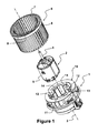
- the figure 1 is an exploded perspective view of a motor-fan unit comprising a motor support 1. It shows, more particularly, the context of use of the motor support 1 according to the invention.
- the figure 1 thus presents a motor-fan unit intended to be mounted on a housing of a heating, ventilation and / or air conditioning system equipping a motor vehicle.
- This motor-fan unit ensures the movement of an air flow inside the housing of the heating, ventilation and / or air conditioning system.
- the motor-fan unit consists of the motor support 1 inside which is mounted an electric motor 2.
- the electric motor 2 comprises a longitudinal axis 3 passing in its center and defining the main axis of the electric motor 2.
- the motor electrical 2 also comprises a shaft 4 extending along the longitudinal axis 3.
- the shaft 4 is supported by the electric motor 2 at each of its ends, for example by bearings or bearings.
- the shaft 4 opens a carcass 5 forming an integral part of the electric motor 2 to form a free end.
- the free end of the shaft 4 receives a blower wheel 6, preferably made of plastic.
- the blower wheel 6 takes the form of a bowl, for example closed or partially perforated, on the periphery of which extends a multiplicity of blades 7.
- the blades 7 are connected, on the one hand towards the inside of the blower wheel 6, to the bowl and, on the other hand, outside the blower wheel 6, to a circular edge 8 joining each of the blades 7.
- the blades 7 extend in a direction parallel to the direction of the longitudinal axis 3 of the electric motor 2.
- the blower wheel 6 thus takes the form of a propeller equipped with axial blades but it could also be a propeller with radial blades, for example flat, where the blades extend substantially perpendicularly to the direction of the rotor. longitudinal axis 3 of the electric motor 2.
- the blower wheel 6 is secured to the shaft 4 by a hub 9 disposed in the center of the bowl and through which passes the free end of the shaft 4 of the electric motor 2.
- the electric motor 2 is held in the motor support 1.
- the motor support 1 comprises an outer ring 10, a receiving member 11 of the electric motor 2 and at least one decoupling means 12 interposed between the outer ring 10 and the receiving member 11.
- the receiving member 11 takes particularly the form of an inner ring 13, for example consisting of a cylindrical portion, at the end of which is installed at least one locking pin 14 of the electric motor 2.
- the pin of blocking 14 thus prevents any movement of the electric motor 2 in the direction of the longitudinal axis 3.
- the decoupling means 12 comprises an adaptive device 15 adapted to modify at least one mechanical characteristic of the decoupling means 12.
- the adaptive device 15 acts on the decoupling means 12 so as to modify or adapt the properties of the decoupling device 12. damping of the decoupling means 12. These damping properties are thus adapted to avoid the creation of vibrations, noise, such as harmonics, or noise related to the unbalance of the assembly consisting of the electric motor 2 and the blower wheel 6.
- the modification or adaptation generated on the decoupling means 12 by the adaptive device 15 is of a mechanical nature.
- it may be a modification of the stiffness of the decoupling means 12.
- the decoupling means 12 is capable of taking at least two different shore hardnesses under the action of the device.
- the action of the adaptive device 15 may be of electrical or mechanical origin.
- the modification or adaptation generated on the decoupling means 12 by the adaptive device 15 may relate to the shape of the decoupling means 12. This results in an adaptation of the damping properties of the decoupling means.
- a support member for example an actuator, comes into contact with a peripheral portion of the decoupling means 12, thus modifying at least one dimension of the decoupling means.
- the adaptive device 15 is thus able to change the general shape of the decoupling means 12.
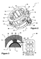
- FIG 2 is a perspective view of the motor support 1 according to the present invention.
- the engine support 1 is made of plastic, for example polypropylene. It has a generally cylindrical, elongated and hollow shape.
- the motor support 1 has a central recess for receiving the electric motor 2.
- the central recess makes it possible to receive the receiving member 11 of the electric motor 2. More particularly, the central recess constitutes a housing for the inner ring 13.
- the inner ring 13 comprises a plurality of locking pins 14, four in number, arranged at each end of the inner ring 13.
- the locking lugs 14 form a stop for the electric motor 2.
- the locking lugs 14 originate on the inner ring 13 and extend radially towards the longitudinal axis 3 in a plane perpendicular to the longitudinal axis 3.
- the outer ring 10 consists of an outer peripheral wall 16.
- the outer peripheral wall 16 surrounds the receiving member 11, in particular the inner ring 13.
- the outer peripheral wall 16 comprises a plurality of securing means 17 intended to ensure fixing the motor support 1 on the housing of the heating, ventilation and / or air conditioning system.
- the motor support 1 is mounted on the casing of the heating, ventilation and / or air conditioning system at a volute arranged in the housing of the heating, ventilation and / or air conditioning system for channeling the air flow generated by the fan motor unit.
- the securing means 17 comprise in particular two ribs extending on the outer peripheral wall 16 in a circumferential direction, thus forming between them a groove for receiving a finger arranged on the housing of the heating, ventilation and / or air conditioning.
- the engine support 1 comprises an intermediate wall 18 connected to the outer peripheral wall 16 by a sidewall 19.
- the sidewall 19 joins the outer peripheral wall 16 with the intermediate wall 18.
- the flank 19 extends in a plane perpendicular to the longitudinal axis 3.
- the outer peripheral wall 16, the intermediate wall 18 and the inner ring 13 take the form of hollow cylindrical tubes arranged in a generally concentric manner with respect to each other, centered on the longitudinal axis 3.
- the engine support 1 comprises three decoupling means 12.
- the intermediate wall 18 is connected to the inner ring 13 by the three decoupling means 12.
- the three decoupling means 12 are identical and, advantageously, uniformly distributed along angular sectors equal to 120 °.
- the decoupling means 12 is made of a material that is more flexible than the material used for the motor support 1 in order to provide an isolation function between the inner ring 13 and the intermediate wall 18 and thus prevent the transmission of the internal vibrations generated. by the electric motor 2 and / or the unbalance of the assembly consisting of the electric motor 2 and the impeller wheel 6.
- the material of the decoupling means 12 is, for example, an elastomer, in particular EPDM or SEBS or rubber.
- the decoupling means 12 has a cross section, in a plane perpendicular to the longitudinal axis 3, in "H", particularly visible on the figures 1 and 2 .
- the section "H” is a particular and non-limiting embodiment of the decoupling means 12.
- the characteristics and dimensions of the decoupling means 12 may be of any geometry.
- the decoupling means 21 is in the form of a parallelepipedic stud comprising a first side in direct contact with the inner ring 13 of the motor support 1.
- the cooperation of the decoupling means 21 with the inner ring 13 can be done, for example, by gluing, clipping, overmoulding or shape cooperation.
- the decoupling means 12 also comprises a second side in direct contact with the intermediate ring 18 of the motor support 1.
- the cooperation of the decoupling means 21 with the intermediate ring 18 can be done, for example, by gluing, clipping, overmoulding or shape cooperation.
- the decoupling means 12 also comprises lateral sides extending parallel to the longitudinal axis 3 of the electric motor 2. According to the preferred example presented, the lateral sides respectively have at least one recess extending in a direction parallel to the longitudinal axis 3. The recess of the lateral sides contributes to defining the "H" section of the decoupling means 12.
- the specific structure of the decoupling means 12 provides vibration isolation between the electric motor 2 and the housing of the heating, ventilation and / or air conditioning system receiving the engine support 1 of all types of vibrations caused by the implementation of the electric motor 2 and the impeller wheel 6.
- the axial and tangential stresses are absorbed by the decoupling means 12.
- the recess arranged on the lateral side of the decoupling means 12 in a direction parallel to the longitudinal axis 3 gives flexibility to the decoupling means 12 with respect to an axial stress and with respect to a tangential stress while maintaining a rigidity of the stud with respect to a radial stress.
- the outer peripheral wall 16 has a docking edge 20.
- the docking edge 20 takes the form of a peripheral collar coming into contact with an edge of the housing of the heating, ventilation and / or air conditioning system.
- the peripheral collar may have a planar profile, in particular a plane perpendicular to the longitudinal axis 3.
- the peripheral collar may have an evolutive profile, in particular according to an axial evolution, in particular a helical profile. .
- the docking edge 20 assembles, advantageously airtight, between the engine support 1 and the housing of the heating, ventilation and / or air conditioning system.
- the engine support 1 also comprises a cooling device 22 of the electric motor 2.
- the cooling device 22 comprises a channel 23 formed on the periphery of the intermediate wall 18. The cooling device 22 ensures the channeling of part of the flow of air, set in motion by the motor-fan unit, via the channel 23 to the electric motor 3.
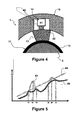
- FIG 3 is a schematic view of a first alternative embodiment of the motor support 1 and a control module 29 according to the present invention.
- figure 3 shows the first embodiment of the adaptive device 15 in which the outer ring 10, the decoupling means 12, the inner ring 13 and the electric motor 2 are shown schematically here.
- the adaptive device 15 is integrated in the material constituting the decoupling means 12.
- the adaptive device 15 is molded inside the pad forming the decoupling means 12.
- the mechanical characteristic modified by the adaptive device 15 is the stiffness of the decoupling means 12.
- the modification or adaptation of the decoupling means 12 is performed by changing the temperature of the constituent material of the decoupling means 12.
- the adaptive device 15 comprises a heating element 25 running inside the means of Decoupling 12.
- the heating element 25 opens out of the decoupling means 12 by two terminals respectively connected to electrical conductors 26 and 27.
- the heating element 25 is thus a heat source making it possible to modify the temperature of the decoupling means 12 and, correspondingly, to adapt the stiffness of the decoupling means 12.
- the heating element 12 may be, for example, a resistive heating element. It may also be a PTC heating element (Positive Temperature Coefficient).
- the adaptive device 15 is constituted by the material of the decoupling means 12 as such.
- the material for example plastic, has electrical properties.
- the material of the decoupling means 12 may be a piezoelectric element, such as a polymer or an elastomer.
- the mechanical characteristic of the decoupling means 12 is modified when the latter is crossed by an electric current, the material of the decoupling means 12 being electrically conductive.
- the mechanical characteristic of the decoupling means 12 modified by the adaptive device 15 is its shape. Indeed, the material of the decoupling means 12 having electrical properties, it is likely to generate mechanical stresses inside the decoupling means 12 tending, for example, to stretch or contract the decoupling means 12. Thus, it the shape of the decoupling means 12 is modified
- the use of a material having electrical properties can also generate a modification of the stiffness of the decoupling means 12, thus making it possible to adapt the damping or anti-vibration properties of the decoupling means 12.
- the figure 3 also illustrates an adaptive decoupling system 28 comprising, on the one hand, the motor support 1 and, on the other hand, a control module 29 of the adaptive device 15 of the decoupling means 12 of the motor support 1.
- the control module 29 receives various input signals 30, 31 and 32 and delivers a control signal 33 to the electrical conductors 26 and 27.
- the input signals 30, 31 and 32 correspond to information that can be measured, for example by a sensor, or evaluated from parameters of the heating, ventilation and / or air-conditioning system or else taken, for example from the the vehicle's electrical network when this information is available.
- the control module 29 is, for example, an autonomous electronic calculator or possibly integrated in another controller existing on the vehicle, for example an electronic control unit for the heating, ventilation and / or air conditioning system.
- the control module 29 takes into account at least a first input signal 30 representative of the internal vibration of the motor support 1, that is to say coming from the electric motor 2 or the blower wheel 6.
- the internal vibration of the motor support 1 is detectable in particular on the receiving member 11 of the electric motor 2.
- the first input signal 30 can come from, for example, an optoelectronic sensor 34 intended to measuring the rotational speed of the shaft of the electric motor 2, which allows to deduce the potential level of vibration.
- the pressure difference between the upstream and the downstream of the motor-fan unit represents a difference between the pressure outside the housing of the the heating, ventilation and / or air conditioning system and the pressure inside the housing of the heating, ventilation and / or air conditioning system after the blower wheel 6 according to the direction of movement of the air flow.
- the first input signal 30, image of the rotational speed of the electric motor 2 is recovered on the control signal of the electric motor 2.
- the control module 29 also takes into account a second input signal 31 representative of a vibration external to the motor support 1, and in particular detectable on the outer ring 10.
- the second input signal 31 may, for example, come from at least one accelerometer 35, for example positioned on the structure of the vehicle, or advantageously on the housing of the heating, ventilation and / or air conditioning system.
- the positioning of the accelerometer 35 on the housing of the heating, ventilation and / or air conditioning system makes it possible to read the level of external vibrations as close as possible to the motor support 1.
- the second input signal 31 may be taken from an accelerometer existing on the vehicle, such as for example an accelerometer used for triggering the active safety systems mounted on the vehicle.
- the control module 29 also takes into account a third signal input 32 representative of an indoor air temperature and / or outside the vehicle cab. It can also be the air inside the heating, ventilation and / or air conditioning system.
- the temperature of the air can thus be measured by at least one temperature sensor 36 installed in the cabin and / or outside. of it and / or inside the volute.
- the control module 29 is a computer, or an electronic circuit, comprising a data acquisition module 37 able to deliver a processing signal to a calculation module 38 capable of delivering a calculation signal to a transformation module 39 to adapted to generate the electrical signal 33 for the adaptive device 15 of the decoupling means 12.
- the figure 4 is a schematic view of a second alternative embodiment of the engine support 1 according to the present invention. More specifically, the figure 4 presents an alternative embodiment of the adaptive device 15, transposable in all points in the adaptive decoupling system 28 described above.
- the figure 4 shows the second variant embodiment of the adaptive device 15 in which the outer ring 10, the decoupling means 12, the inner ring 13 and the electric motor 2 are shown schematically here.
- the outer ring 10 comprises a housing 40.
- the housing 40 is made, for example, in the thickness of the outer ring 10.
- the housing 40 receives the adaptive device 15 of the decoupling means 12.
- the adaptive device 15 takes the form of an actuator 41, advantageously electric or pneumatic.
- the adaptive device 15 of the decoupling means 12 is inside the decoupling means, according to the embodiment of the figure 4 , the adaptive device 15, for example the actuator 41, is installed outside the decoupling means 12.
- the adaptive device 15 is therefore distinct and separate from the decoupling means 12.
- the actuator 41 exerts a force on the decoupling means 12, for example by means of an arm 42 set in motion by the actuator 41.
- the arm 42 bears against at least one of the faces of the decoupling means 12.
- the arm 42 may for example be replaced by a cam.
- the face of the decoupling means 12 undergoing the pressure exerted by the adaptive device 15 is the second face, that is to say the face opposite to the first face of the decoupling means 12 in contact with the inner ring 13.
- the adaptive device 15 thus modifies a mechanical characteristic of the decoupling means 12 by applying a force generated by the adaptive device 15, for example the actuator 41, on the decoupling means 12.
- the figure 5 is a comparative graph of the engine support 1 according to the present invention and a motor support according to the prior art.
- the figure 5 illustrates the effects of the present invention in the form of curves comparing the accelerations observed on an outer ring of a motor support of the prior art with the accelerations observed on the outer ring 10 of the engine support 1 according to the present invention.
- the graph of the figure 5 includes a reference curve 44, presented in as an example in the form of a line on the figure 5 , illustrating an acceleration observed on an outer ring of a motor support equipped with a decoupling transmitting integrally and without amplification the vibration emitted by the imbalance, or unbalance, of the assembly consisting of the electric motor 2 and the impeller wheel 6.
- the reference curve 44 is, for example, obtained by measuring vibrations on a motor support having said decoupling means "hard".
- so-called 'hard' decoupling means avoid amplifying the vibration associated with unbalance (or harmonic H1). But, such decoupling means said 'hard' are penalizing for higher harmonics (for example harmonic H12, harmonic H24, ...), which can result in noise at a higher frequency than the noise related unbalance. Under such circumstances, a so-called 'flexible' decoupling means makes it possible to filter the higher harmonics.
- the curve in thin line 43 illustrates the vibratory behavior of the motor support according to the prior art.
- the presence of vibratory peaks present at the eigenfrequencies 46 and 47 of the decoupling means 12 is observed.
- blower wheel 6 is likely to be damaged.
- the adaptive device 15 modifies the rigidity of the decoupling means 12, if strong external stresses appear, whatever the speed of rotation of the electric motor 2.
- the curve in strong line 45 shows the vibratory behavior of the motor support 1 according to the present invention. It can be seen that the vibratory peaks at eigenfrequencies 46 and 47 are suppressed. Moreover, for all the rotational speeds of the electric motor 2, the accelerations measured on the outer ring 10 of the motor support 1 are below the reference curve 44. Thus, the decoupling means 12 comprising the adaptive device 15 is therefore perfect over the entire frequency range of rotation of the electric motor 2.
- the adaptive decoupling system 28 detects, at a frequency 48, a crossing of the threshold determined by the reference curve 44 and activates the adaptive device 15 to, in this example, harden the decoupling means 12.
- the stiffness of the decoupling means 12 is increased by means of the adaptive device 15, until the adaptive decoupling system 28 detects, at a frequency 49, the activation end of the adaptive device 15.
- the engine support 1 according to the present invention thus ensures a good vibro-acoustic decoupling in a majority of vehicle use situations while increasing the stiffness of the decoupling means 12 in high stress situations vibratory, coming from inside or outside the motor support 1.
- the figure 5 shows a similar situation for rotation frequencies of the higher electric motor 2, for example between frequencies 50 and 51.
Landscapes
- Engineering & Computer Science (AREA)
- General Engineering & Computer Science (AREA)
- Mechanical Engineering (AREA)
- Power Engineering (AREA)
- Physics & Mathematics (AREA)
- Chemical & Material Sciences (AREA)
- Thermal Sciences (AREA)
- Combustion & Propulsion (AREA)
- Acoustics & Sound (AREA)
- Aviation & Aerospace Engineering (AREA)
- Structures Of Non-Positive Displacement Pumps (AREA)
- Motor Or Generator Frames (AREA)
- Air-Conditioning For Vehicles (AREA)
Applications Claiming Priority (1)
| Application Number | Priority Date | Filing Date | Title |
|---|---|---|---|
| FR1101216A FR2974464B1 (fr) | 2011-04-19 | 2011-04-19 | Support-moteur a moyens de decouplage adaptatifs |
Publications (2)
| Publication Number | Publication Date |
|---|---|
| EP2515418A2 true EP2515418A2 (de) | 2012-10-24 |
| EP2515418A3 EP2515418A3 (de) | 2016-11-30 |
Family
ID=46049137
Family Applications (1)
| Application Number | Title | Priority Date | Filing Date |
|---|---|---|---|
| EP12002661.2A Withdrawn EP2515418A3 (de) | 2011-04-19 | 2012-04-17 | Motorhalterung mit adaptativen Entkopplungsmitteln |
Country Status (2)
| Country | Link |
|---|---|
| EP (1) | EP2515418A3 (de) |
| FR (1) | FR2974464B1 (de) |
Cited By (7)
| Publication number | Priority date | Publication date | Assignee | Title |
|---|---|---|---|---|
| WO2014080175A1 (en) * | 2012-11-21 | 2014-05-30 | Dyson Technology Limited | A hand dryer |
| CN106050749A (zh) * | 2015-04-08 | 2016-10-26 | 马勒国际有限公司 | 鼓风机装置 |
| US20170110932A1 (en) * | 2014-06-27 | 2017-04-20 | Brose Fahrzeugteile Gmbh & Co. Kommanditgesellschaft, Wuerzburg | Device for the vibration-decoupled mounting of a motor |
| CN106762792A (zh) * | 2016-12-16 | 2017-05-31 | 宁波方太厨具有限公司 | 一种减震密封垫及应用有该减震密封垫的离心风机 |
| US10018417B2 (en) | 2012-11-21 | 2018-07-10 | Dyson Technology Limited | Hand dryer |
| DE102019202432A1 (de) * | 2019-02-22 | 2020-08-27 | Ziehl-Abegg Se | Ventilator und Verfahren zum optimierten Betrieb eines Ventilators sowie zur Optimierung des Schwingungsverhaltens eines Ventilators |
| US20230003224A1 (en) * | 2019-10-28 | 2023-01-05 | Valeo Systemes Thermiques | Mechanical assembly for a vehicle and ventilator device for a vehicle comprising such a mechanical assembly |
Families Citing this family (2)
| Publication number | Priority date | Publication date | Assignee | Title |
|---|---|---|---|---|
| FR3030617B1 (fr) * | 2014-12-12 | 2019-07-19 | Valeo Systemes De Controle Moteur | Machine electrique |
| FR3105101B1 (fr) | 2019-12-18 | 2021-11-26 | Valeo Systemes Thermiques | Element de decouplage pour un support de moteur comprenant un fluide non newtonien |
Family Cites Families (5)
| Publication number | Priority date | Publication date | Assignee | Title |
|---|---|---|---|---|
| US3317124A (en) * | 1964-11-19 | 1967-05-02 | Wayne J Morrill | Motor vibration isolating mounting |
| DE4306588A1 (de) * | 1992-07-14 | 1994-01-20 | Bosch Gmbh Robert | Schwingungsdämpfende Halterung von Elektromotoren |
| JP2001277834A (ja) * | 2000-03-28 | 2001-10-10 | Denso Corp | 駆動源の支持構造 |
| US6378671B1 (en) * | 2000-03-29 | 2002-04-30 | Lord Corporation | Magnetically actuated motion control device |
| KR100469470B1 (ko) * | 2003-01-30 | 2005-02-02 | 엘지전자 주식회사 | 열변형을 이용한 댐퍼 및 이를 구비한 세탁기 |
-
2011
- 2011-04-19 FR FR1101216A patent/FR2974464B1/fr active Active
-
2012
- 2012-04-17 EP EP12002661.2A patent/EP2515418A3/de not_active Withdrawn
Cited By (11)
| Publication number | Priority date | Publication date | Assignee | Title |
|---|---|---|---|---|
| WO2014080175A1 (en) * | 2012-11-21 | 2014-05-30 | Dyson Technology Limited | A hand dryer |
| US9986877B2 (en) | 2012-11-21 | 2018-06-05 | Dyson Technology Limited | Hand dryer |
| US10018417B2 (en) | 2012-11-21 | 2018-07-10 | Dyson Technology Limited | Hand dryer |
| US20170110932A1 (en) * | 2014-06-27 | 2017-04-20 | Brose Fahrzeugteile Gmbh & Co. Kommanditgesellschaft, Wuerzburg | Device for the vibration-decoupled mounting of a motor |
| US10432058B2 (en) * | 2014-06-27 | 2019-10-01 | Brose Fahrzeugtelle GmbH & Co. Kommanditgesellschaft, Wuerzburg | Device for the vibration-decoupled mounting of a motor |
| CN106050749A (zh) * | 2015-04-08 | 2016-10-26 | 马勒国际有限公司 | 鼓风机装置 |
| CN106050749B (zh) * | 2015-04-08 | 2020-01-03 | 马勒国际有限公司 | 鼓风机装置 |
| CN106762792A (zh) * | 2016-12-16 | 2017-05-31 | 宁波方太厨具有限公司 | 一种减震密封垫及应用有该减震密封垫的离心风机 |
| CN106762792B (zh) * | 2016-12-16 | 2022-11-25 | 宁波方太厨具有限公司 | 一种减震密封垫及应用有该减震密封垫的离心风机 |
| DE102019202432A1 (de) * | 2019-02-22 | 2020-08-27 | Ziehl-Abegg Se | Ventilator und Verfahren zum optimierten Betrieb eines Ventilators sowie zur Optimierung des Schwingungsverhaltens eines Ventilators |
| US20230003224A1 (en) * | 2019-10-28 | 2023-01-05 | Valeo Systemes Thermiques | Mechanical assembly for a vehicle and ventilator device for a vehicle comprising such a mechanical assembly |
Also Published As
| Publication number | Publication date |
|---|---|
| FR2974464B1 (fr) | 2016-02-05 |
| FR2974464A1 (fr) | 2012-10-26 |
| EP2515418A3 (de) | 2016-11-30 |
Similar Documents
| Publication | Publication Date | Title |
|---|---|---|
| EP2515418A2 (de) | Motorhalterung mit adaptativen Entkopplungsmitteln | |
| EP2656488B1 (de) | Motorträger mit verbesserter entkopplung für ein belüftungssystem | |
| EP1634737B1 (de) | Träger mit Mitteln zur Absorption von Vibrationen eines Lüftermotors | |
| EP2383490B1 (de) | Entkupplungsriemenscheibe | |
| CA2754090A1 (fr) | Element de rotor avec un passage de fluide et un element d'obturation du passage, turbomachine comportant l'element de rotor | |
| EP3558798B1 (de) | Abklappbares aerodynamisches system für ein kraftfahrzeug | |
| EP2586119A2 (de) | Motorbefestigung mit einer vorrichtung zum begrenzung von bewegungen | |
| EP2839166B1 (de) | Laufrad für ein kraftfahrzeuggebläse mit segmentierten nabenversteifungen | |
| WO2020260815A1 (fr) | Support de moteur pour dispositif de chauffage, de ventilation et/ou de climatisation pour vehicule automobile | |
| WO2021123548A1 (fr) | Coupelle de rotor exterieur pour un moteur de ventilateur d'un vehicule automobile | |
| EP3580836B1 (de) | Luftpulsvorrichtung für eine heizungs-, lüftungs- oder klimaanlage eines kraftfahrzeugs | |
| EP1707843B1 (de) | Zweimassenschwungrad für ein Kraftfahrzeug | |
| EP3453103B1 (de) | Geräuschreduzierendes bauteil auf dem gehäuse eines elektromotors | |
| WO2021170949A1 (fr) | Groupe moto-ventilateur à élément de contact en contact avec une roue de ventilateur et une coupelle du rotor, pour installation de chauffage, ventilation et/ou climatisation de véhicule automobile | |
| EP3991277A1 (de) | Halterung für einen motor für eine heizungs-, lüftungs- und/oder klimaanlage für ein kraftfahrzeug | |
| WO2021249863A1 (fr) | Support de moteur de ventilateur avec amortisseur et butée | |
| WO2021123543A1 (fr) | Element de decouplage pour un support de moteur comprenant un fluide non newtonien | |
| WO2021249862A1 (fr) | Support de moteur et ventilateur pour une installation de chauffage, ventilation et/ou climatisation pour un vehicule automobile | |
| WO2023110940A1 (fr) | Groupe moto-ventilateur pour installation de chauffage, ventilation et/ou climatisation d'un véhicule automobile équipé d'un moyen de contact posé entre une coupelle et un moyeu | |
| EP2420707B1 (de) | Einheit für ein Lenksystem eines Fahrzeugs | |
| WO2021123547A1 (fr) | Moteur pour dispositif de ventilation d'une installation de chauffage, ventilation et/ou climatisation de vehicule automobile a rotor et stator decouples d'une embase de montage | |
| EP3327905A1 (de) | Elektrische maschine für kraftfahrzeug | |
| FR3004027A1 (fr) | Piece de decouplage entre un moteur et son support, et assemblage d'un moteur sur son support integrant une telle piece de decouplage | |
| WO2025045503A1 (fr) | Groupe motopropulseur électrique pour véhicule motorisé | |
| WO2021084178A1 (fr) | Ensemble mécanique pour véhicule et dispositif de ventilateur pour véhicule comprenant un tel ensemble mécanique |
Legal Events
| Date | Code | Title | Description |
|---|---|---|---|
| PUAI | Public reference made under article 153(3) epc to a published international application that has entered the european phase |
Free format text: ORIGINAL CODE: 0009012 |
|
| AK | Designated contracting states |
Kind code of ref document: A2 Designated state(s): AL AT BE BG CH CY CZ DE DK EE ES FI FR GB GR HR HU IE IS IT LI LT LU LV MC MK MT NL NO PL PT RO RS SE SI SK SM TR |
|
| AX | Request for extension of the european patent |
Extension state: BA ME |
|
| PUAL | Search report despatched |
Free format text: ORIGINAL CODE: 0009013 |
|
| AK | Designated contracting states |
Kind code of ref document: A3 Designated state(s): AL AT BE BG CH CY CZ DE DK EE ES FI FR GB GR HR HU IE IS IT LI LT LU LV MC MK MT NL NO PL PT RO RS SE SI SK SM TR |
|
| AX | Request for extension of the european patent |
Extension state: BA ME |
|
| RIC1 | Information provided on ipc code assigned before grant |
Ipc: B60H 1/00 20060101ALI20161025BHEP Ipc: F04D 25/08 20060101ALI20161025BHEP Ipc: H02K 11/00 20160101ALI20161025BHEP Ipc: F16F 15/08 20060101ALI20161025BHEP Ipc: F04D 29/66 20060101ALI20161025BHEP Ipc: H02K 5/24 20060101AFI20161025BHEP Ipc: F16F 1/36 20060101ALI20161025BHEP |
|
| STAA | Information on the status of an ep patent application or granted ep patent |
Free format text: STATUS: THE APPLICATION IS DEEMED TO BE WITHDRAWN |
|
| 18D | Application deemed to be withdrawn |
Effective date: 20170531 |