EP2514939A2 - Abgasanlagenkomponente mit thermischer Isolierung - Google Patents
Abgasanlagenkomponente mit thermischer Isolierung Download PDFInfo
- Publication number
- EP2514939A2 EP2514939A2 EP12163904A EP12163904A EP2514939A2 EP 2514939 A2 EP2514939 A2 EP 2514939A2 EP 12163904 A EP12163904 A EP 12163904A EP 12163904 A EP12163904 A EP 12163904A EP 2514939 A2 EP2514939 A2 EP 2514939A2
- Authority
- EP
- European Patent Office
- Prior art keywords
- exhaust system
- cavity
- system component
- component according
- skin
- Prior art date
- Legal status (The legal status is an assumption and is not a legal conclusion. Google has not performed a legal analysis and makes no representation as to the accuracy of the status listed.)
- Granted
Links
Images

Classifications
-
- F—MECHANICAL ENGINEERING; LIGHTING; HEATING; WEAPONS; BLASTING
- F01—MACHINES OR ENGINES IN GENERAL; ENGINE PLANTS IN GENERAL; STEAM ENGINES
- F01N—GAS-FLOW SILENCERS OR EXHAUST APPARATUS FOR MACHINES OR ENGINES IN GENERAL; GAS-FLOW SILENCERS OR EXHAUST APPARATUS FOR INTERNAL-COMBUSTION ENGINES
- F01N13/00—Exhaust or silencing apparatus characterised by constructional features
- F01N13/16—Selection of particular materials
-
- F—MECHANICAL ENGINEERING; LIGHTING; HEATING; WEAPONS; BLASTING
- F01—MACHINES OR ENGINES IN GENERAL; ENGINE PLANTS IN GENERAL; STEAM ENGINES
- F01N—GAS-FLOW SILENCERS OR EXHAUST APPARATUS FOR MACHINES OR ENGINES IN GENERAL; GAS-FLOW SILENCERS OR EXHAUST APPARATUS FOR INTERNAL-COMBUSTION ENGINES
- F01N13/00—Exhaust or silencing apparatus characterised by constructional features
- F01N13/14—Exhaust or silencing apparatus characterised by constructional features having thermal insulation
- F01N13/141—Double-walled exhaust pipes or housings
-
- F—MECHANICAL ENGINEERING; LIGHTING; HEATING; WEAPONS; BLASTING
- F01—MACHINES OR ENGINES IN GENERAL; ENGINE PLANTS IN GENERAL; STEAM ENGINES
- F01N—GAS-FLOW SILENCERS OR EXHAUST APPARATUS FOR MACHINES OR ENGINES IN GENERAL; GAS-FLOW SILENCERS OR EXHAUST APPARATUS FOR INTERNAL-COMBUSTION ENGINES
- F01N13/00—Exhaust or silencing apparatus characterised by constructional features
- F01N13/14—Exhaust or silencing apparatus characterised by constructional features having thermal insulation
- F01N13/141—Double-walled exhaust pipes or housings
- F01N13/143—Double-walled exhaust pipes or housings with air filling the space between both walls
-
- F—MECHANICAL ENGINEERING; LIGHTING; HEATING; WEAPONS; BLASTING
- F01—MACHINES OR ENGINES IN GENERAL; ENGINE PLANTS IN GENERAL; STEAM ENGINES
- F01N—GAS-FLOW SILENCERS OR EXHAUST APPARATUS FOR MACHINES OR ENGINES IN GENERAL; GAS-FLOW SILENCERS OR EXHAUST APPARATUS FOR INTERNAL-COMBUSTION ENGINES
- F01N13/00—Exhaust or silencing apparatus characterised by constructional features
- F01N13/14—Exhaust or silencing apparatus characterised by constructional features having thermal insulation
- F01N13/141—Double-walled exhaust pipes or housings
- F01N13/146—Double-walled exhaust pipes or housings with vacuum in the space between both walls
-
- F—MECHANICAL ENGINEERING; LIGHTING; HEATING; WEAPONS; BLASTING
- F01—MACHINES OR ENGINES IN GENERAL; ENGINE PLANTS IN GENERAL; STEAM ENGINES
- F01N—GAS-FLOW SILENCERS OR EXHAUST APPARATUS FOR MACHINES OR ENGINES IN GENERAL; GAS-FLOW SILENCERS OR EXHAUST APPARATUS FOR INTERNAL-COMBUSTION ENGINES
- F01N3/00—Exhaust or silencing apparatus having means for purifying, rendering innocuous, or otherwise treating exhaust
- F01N3/02—Exhaust or silencing apparatus having means for purifying, rendering innocuous, or otherwise treating exhaust for cooling, or for removing solid constituents of, exhaust
- F01N3/04—Exhaust or silencing apparatus having means for purifying, rendering innocuous, or otherwise treating exhaust for cooling, or for removing solid constituents of, exhaust using liquids
- F01N3/043—Exhaust or silencing apparatus having means for purifying, rendering innocuous, or otherwise treating exhaust for cooling, or for removing solid constituents of, exhaust using liquids without contact between liquid and exhaust gases
-
- F—MECHANICAL ENGINEERING; LIGHTING; HEATING; WEAPONS; BLASTING
- F01—MACHINES OR ENGINES IN GENERAL; ENGINE PLANTS IN GENERAL; STEAM ENGINES
- F01N—GAS-FLOW SILENCERS OR EXHAUST APPARATUS FOR MACHINES OR ENGINES IN GENERAL; GAS-FLOW SILENCERS OR EXHAUST APPARATUS FOR INTERNAL-COMBUSTION ENGINES
- F01N3/00—Exhaust or silencing apparatus having means for purifying, rendering innocuous, or otherwise treating exhaust
- F01N3/02—Exhaust or silencing apparatus having means for purifying, rendering innocuous, or otherwise treating exhaust for cooling, or for removing solid constituents of, exhaust
- F01N3/04—Exhaust or silencing apparatus having means for purifying, rendering innocuous, or otherwise treating exhaust for cooling, or for removing solid constituents of, exhaust using liquids
- F01N3/043—Exhaust or silencing apparatus having means for purifying, rendering innocuous, or otherwise treating exhaust for cooling, or for removing solid constituents of, exhaust using liquids without contact between liquid and exhaust gases
- F01N3/046—Exhaust manifolds with cooling jacket
-
- F—MECHANICAL ENGINEERING; LIGHTING; HEATING; WEAPONS; BLASTING
- F01—MACHINES OR ENGINES IN GENERAL; ENGINE PLANTS IN GENERAL; STEAM ENGINES
- F01N—GAS-FLOW SILENCERS OR EXHAUST APPARATUS FOR MACHINES OR ENGINES IN GENERAL; GAS-FLOW SILENCERS OR EXHAUST APPARATUS FOR INTERNAL-COMBUSTION ENGINES
- F01N3/00—Exhaust or silencing apparatus having means for purifying, rendering innocuous, or otherwise treating exhaust
- F01N3/02—Exhaust or silencing apparatus having means for purifying, rendering innocuous, or otherwise treating exhaust for cooling, or for removing solid constituents of, exhaust
- F01N3/05—Exhaust or silencing apparatus having means for purifying, rendering innocuous, or otherwise treating exhaust for cooling, or for removing solid constituents of, exhaust by means of air, e.g. by mixing exhaust with air
- F01N3/055—Exhaust or silencing apparatus having means for purifying, rendering innocuous, or otherwise treating exhaust for cooling, or for removing solid constituents of, exhaust by means of air, e.g. by mixing exhaust with air without contact between air and exhaust gases
-
- F—MECHANICAL ENGINEERING; LIGHTING; HEATING; WEAPONS; BLASTING
- F01—MACHINES OR ENGINES IN GENERAL; ENGINE PLANTS IN GENERAL; STEAM ENGINES
- F01N—GAS-FLOW SILENCERS OR EXHAUST APPARATUS FOR MACHINES OR ENGINES IN GENERAL; GAS-FLOW SILENCERS OR EXHAUST APPARATUS FOR INTERNAL-COMBUSTION ENGINES
- F01N2260/00—Exhaust treating devices having provisions not otherwise provided for
- F01N2260/02—Exhaust treating devices having provisions not otherwise provided for for cooling the device
- F01N2260/024—Exhaust treating devices having provisions not otherwise provided for for cooling the device using a liquid
-
- Y—GENERAL TAGGING OF NEW TECHNOLOGICAL DEVELOPMENTS; GENERAL TAGGING OF CROSS-SECTIONAL TECHNOLOGIES SPANNING OVER SEVERAL SECTIONS OF THE IPC; TECHNICAL SUBJECTS COVERED BY FORMER USPC CROSS-REFERENCE ART COLLECTIONS [XRACs] AND DIGESTS
- Y02—TECHNOLOGIES OR APPLICATIONS FOR MITIGATION OR ADAPTATION AGAINST CLIMATE CHANGE
- Y02T—CLIMATE CHANGE MITIGATION TECHNOLOGIES RELATED TO TRANSPORTATION
- Y02T10/00—Road transport of goods or passengers
- Y02T10/10—Internal combustion engine [ICE] based vehicles
- Y02T10/12—Improving ICE efficiencies
Definitions
- the present invention relates to an exhaust system component for an exhaust system of an internal combustion engine, in particular of a motor vehicle.
- the invention also relates to an exhaust system equipped with at least one such component.
- Such exhaust system components include, for example, exhaust treatment devices such as catalytic converters, particulate filters and mufflers, intake manifolds, tailpipes and pipe sections for connecting exhaust treatment devices, manifolds and tailpipes.
- exhaust treatment devices such as catalytic converters, particulate filters and mufflers
- intake manifolds such as catalytic converters, particulate filters and mufflers
- tailpipes such as a particulate filters and mufflers
- pipe sections for connecting exhaust treatment devices, manifolds and tailpipes.
- the present invention is concerned with the problem of providing for an exhaust system component or for an exhaust system an improved embodiment, which is characterized in particular by an improved thermal insulation.
- the invention is based on the general idea to use for thermal insulation at least one dimensionally stable shaped body, which is made porous or consists of a porous insulating material.
- the molded body is arranged between an inner skin, which delimits an exhaust-carrying inner region, and an outer skin arranged on the outer skin.
- Such a porous molded body is distinguished from conventional mat-like fiber-containing insulating materials by a significantly lower coefficient of thermal conductivity.
- a particularly effective thermal insulation of the respective exhaust system component can be achieved with the aid of such porous molded body.
- the molded body has its own carrying capacity or dimensional stability, whereby a certain stiffening of the respective exhaust system component can be achieved via the molded body. Because the molded body can support the inner skin against the outer skin.
- the respective shaped body can be configured rigid, which supports the supporting function of the shaped body. Additionally or alternatively, the shaped body can be adapted to the shape of the cavity formed between the inner skin and the outer skin. As a result, the respective molded body is substantially self-supporting, which simplifies its handling.
- the shaped body is microporous or consists of a microporous insulation material. Suitable microporous materials for producing such shaped bodies are, for example, fumes of fumed silica or of airgel.
- the microporous insulation material may have a pore size of about 10 to 50 nm, preferably about 20 nm.
- the mean free path length for gas molecules can thereby be reduced to such an extent that heat transfer by convection can be significantly reduced within the microporous structure of the shaped body.
- material particles of the insulating material, from which the porous shaped body is manufactured have a spherical shape, whereby touching abutting material particles only in very small contact points, which greatly reduces heat transfer by conduction within the porous structure of the molding.
- the porous insulating material of the molded article may additionally or alternatively be admixed with materials or substances which have an absorbing action in the infrared range of light. This makes it possible to significantly reduce heat transfer by heat radiation within the porous molding.
- the insulation may comprise a plurality of microporous shaped bodies, wherein at least two shaped bodies engage in one another in a form-fitting manner.
- the moldings can be fixed in position relative to one another without the need for expensive attachment measures.
- a segmentation of the moldings in particular when the inner wall is designed as a channel or pipe and surrounds the gas-conducting inner area.
- the outer skin expediently encloses the inner skin annularly, whereby an annular cavity is formed, in which the insulation is housed. Segmented moldings are particularly easy to insert into this cavity.
- the cavity can be designed to be waterproof and gas-impermeable to the surroundings of the exhaust system body. This prevents the spray from the environment can enter the cavity.
- the outer skin may contain at least one opening which is closed by means of a waterproof and gas-permeable membrane, for example in the form of a microperforated metal foil.
- a vent be connected to the cavity, preferably to the outer skin, by means of which a pressure compensation is possible.
- the cavity may be designed to be waterproof and gas-impermeable to the surroundings of the exhaust system components.
- the outer skin may include at least one opening, which is covered by a scoop, which forms with the outer skin a distance from the opening of the outer skin opening to the environment. This allows pressure equalization with sufficient splash protection.
- the inner skin and the outer skin can be tubular, while the cavity and the insulation are designed annular.
- the respective molded body is then also designed annular or ring segment-shaped in order to use it easily in the respective cavity during assembly of the exhaust system component can.
- a longitudinal section of the tubular inner skin may be formed by a bellows.
- a bellows This makes it possible to firmly connect the inner skin at its longitudinal ends with the outer skin. Thermally induced stretching effects can be compensated by the bellows.
- Such a bellows can be configured in one or more layers.
- an embodiment in which the bellows is covered with a guide tube on a side facing the interior area is particularly expedient. As a result, the flow resistance of the tubular inner skin, whose inner contour is disturbed by the bellows, can be reduced in the area of the bellows.
- the guide tube can cover the bellows almost flush with adjacent longitudinal sections of the inner skin, so that the inner contour of the inner skin in the region of the bellows is not or only slightly disturbed.
- the bellows extends from the inner skin in the radial direction only outwards, ie into the cavity.
- the guide tube is axially fixed at a longitudinal end relative to the inner skin or relative to the bellows and, moreover, is loose relative to the inner skin and relative to the bellows.
- a pressure adjusting device can be provided, with the aid of which the pressure prevailing in the cavity is parameter-dependent adjustable.
- the heat transfer between inner skin and outer skin, in particular by convection, depends strongly on the pressure in the cavity. For example, if the thermal insulation is to be improved, the pressure in the cavity may be lowered below ambient pressure to achieve a more or less pronounced vacuum. This can be advantageous, for example during cold start operation. If, on the other hand, a particularly high thermal insulation is no longer required, the pressure in the cavity can be increased, for example to ambient pressure or to a slight overpressure, in order to thermally reduce the component load.
- a filling and emptying device may be provided, with the help of which, depending on the parameter, the cavity can be filled with a heat conducting liquid and emptied therefrom.
- the cavity can be filled with a heat transfer fluid, whereby the heat transfer between the inner skin and outer skin is significantly increased. In particular, this can more or less circumvent the thermally insulating effect of the respective shaped body.
- the filling and emptying device the cavity is again emptied of the heat transfer fluid.
- Suitable skilletleitcremekeiten are, for example, water, glycol and the like.
- a conduit for removing and supplying the heat conducting liquid is expedient in the installed state below, in particular at the lowest point, connected to the cavity in order to achieve the greatest possible emptying can.
- an opening for loading and venting of the cavity may be provided in the installed state above, in particular at the highest point.
- a suitable valve device may also be provided.
- the aforementioned pressure adjusting device and / or the above-mentioned filling and emptying device may have a pump connected to the cavity and a controller for parameter-dependent actuation of the pump.
- Suitable parameters for actuating the respective device are vehicle parameters or state parameters of the internal combustion engine, in particular the temperature of the internal combustion engine or of the exhaust system and its components.
- the respective shaped body expediently has an open-pore structure, in particular when the cavity can be filled with a heat conducting fluid and / or when the pressure in the cavity can be controlled.
- the outer skin may be configured as a supporting structure, while the inner skin is expediently designed as a non-supporting structure.
- the outer skin can be particularly easily used for integrating the respective component in the exhaust system, while the inner skin is mainly used for exhaust system.
- the outer skin may be thick-walled compared to the inner skin, while the inner skin is correspondingly thin-walled compared to the outer skin.
- the outer skin can be realized relatively inexpensively, for example of a ferrite material, since it is only exposed to a greatly reduced thermal load.
- the inner skin is made of a comparatively expensive, corrosion resistant material, such as austenite material.
- austenite material such as austenite material
- the exhaust system component formed by means of the inner skin, the at least one molded body and the outer skin is in particular a pipe or a housing for an exhaust gas treatment device.
- said component may be an intake manifold or a tailpipe.
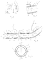
- FIG. 1 includes an exhaust system 1, which serves for discharging combustion exhaust gases from an internal combustion engine, not shown, and in particular can be arranged together with this internal combustion engine in a vehicle, such as an oxidation catalyst 2, a muffler 3 and an exhaust pipe 4, the oxidation catalyst 2 with the muffler 3 connects.
- the exhaust gas turbine components 5 are, for example, an intake manifold, a turbine of an exhaust gas turbocharger, a particulate filter, an SCR catalytic converter, a NOX storage catalytic converter and a tailpipe.
- the exhaust system component 5 in the example so the exhaust pipe 4 an inner skin 6, which limits an inner region 7.
- this inner region 7 serves for exhaust gas routing.
- the inner skin 6 is also tubular, so that it encloses the inner region 7.
- the respective component 5 comprises an outer skin 8, which is arranged on an outer side of the inner skin 6 facing away from the inner region 7, such that a cavity 9 is formed between inner skin 6 and outer skin 8.
- the outer skin 8 is also tubular, so that it encloses the inner skin 6 coaxially.
- a thermal insulation 10 is arranged, which has according to the invention at least one microporous molding 11.
- the respective molded body 11 is designed dimensionally stable and rigid. Furthermore, the shaped body 11 designed as a shaped body 11 is largely adapted to the shape of the cavity 9.
- the insulation 10 expediently comprises a plurality of shaped bodies 11. These can be configured, for example, such that adjacent or adjoining shaped bodies 11 intermesh with one another in a form-fitting manner.
- frame-like contours or tongue and groove contours 12 can be seen, via which adjacent shaped body 11 axially engage with each other and thereby overlap radially.
- frame-like contours or tongue and groove contours 13 can be seen, via which segment-like molded body 11 engage in the circumferential direction into one another and thereby overlap radially.
- the respective moldings 11 are provided with matching depressions 15, in which the projections 14 of the outer skin 8 are positively radially intervention. In this way, an effective positional fixation of the shaped body 11 concerned can be realized.
- the in the FIGS. 2 and 3 embodiment shown is equipped with a splash guard 16 for the cavity 9.
- the cavity 9 is designed to be spritzwassergestrictt the environment of the exhaust system 1 and gas-permeable.
- the gas permeability is realized by means of at least one opening 17, which is designed for this purpose in the outer skin 8.
- This opening 17 is covered by a scoop 18.
- This scoop 18 forms together with the outer skin 8, a further opening 19 to the environment, which is spaced from the aforementioned opening 17 of the outer skin 8.
- the splash guard 16 is formed by means of the scoop 18. Visible, the scoop 18 apart from its opening 19, moreover, firmly and tightly connected to the outer skin 8, which in particular results in a U-shaped contact contour.
- FIGS. 4 and 5 an embodiment in which the cavity 9 is configured to the environment of the exhaust system component 5 out waterproof and gas-permeable.
- the outer skin 8 contains at least one opening 20 which is closed by means of a membrane 21, this membrane 21 being designed to be waterproof and gas-permeable.
- the outer skin 8 is again provided with an opening 17 or 20, to which opening 17, 20 a pipe section 22 is connected.
- This pipe section 22 can now serve as a splash guard 16 or according to Fig. 8 be used to connect a line 23.
- This line 23 can be used in particular for the realization of a venting of the cavity 9.
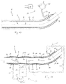
- Fig. 10 with the help of the line 23, a pressure adjusting device 24 via the line 23 to the cavity 9 connect.
- the pressure prevailing in the cavity 9 pressure can be adjusted depending on parameters.
- the pressure adjustment device 24 comprises a suction side of the cavity 9 fluidly connected evacuation pump 25 and a controller 26 for actuating the pump 25 depending on parameters.
- Suitable parameters are in particular vehicle parameters or condition parameters of the internal combustion engine. For example, should be evacuated for a Kaltstaltvorgang the cavity 9 in order to improve the thermal insulation. Once the respective exhaust system component 5 and the exhaust system 1 has reached its normal operating temperature, the vacuum can be reversed, since then a reduced thermal insulation is sufficient.
- a filling and emptying device 27 may be connected.
- a device 27 includes, for example, a conveyor 28 with a reversible conveying direction and a tank 29 for storing a heat conducting fluid 30, such as water or glycol.
- a heat conducting fluid 30 such as water or glycol.
- the cavity 9 can be filled more or less with the heat-conducting fluid 30.
- the heat-conducting fluid 30 can be removed again from the cavity 9. Due to the more or less strong filling of the cavity 9 with the heat conducting liquid 30, the thermal insulating effect of the respective molded body 11 is correspondingly more or less reduced.
- said device 27 can be used to adjust the thermal insulation 10 as needed.
- the use of such a device 27 presupposes that the respective porous material from which the shaped bodies 11 are made have sufficient resistance to the heat-conducting fluid 30 used.
- the filling and emptying device 37 is expediently also analogous to the pressure adjustment device 24 equipped with a controller 26 to actuate the conveyor 28 depending on the incoming parameters.
- the parameters may be the same as in the previously described embodiment with the pressure adjustment device 24.
- a conduit 38 for removing and supplying the heat-conducting fluid 30 is expedient in the installed state below, in particular at the lowest point, connected to the cavity 9 in order to achieve the greatest possible emptying can.
- the outer skin 8 penetrating opening 17 or 20 is provided.
- an opening 17 or 20 may be provided for loading and venting of the cavity 9.
- a suitable valve device (not shown) may be provided.
- the upper-lying ventilation opening 17 and 20 is connected via a ventilation line 23 to the storage tank 29.
- the back-and-forth conveyed liquid 30 displaces in the respective to be filled with the liquid 30 target space, namely the cavity 9 during filling and the tank 29 during emptying, just as much air or other gas, such as the respective output space from which the liquid is withdrawn, namely the tank 29 during filling and the cavity 9 when emptying, must be refilled.
- the direct connection of the two rooms (9 and 29) thus also the air or the respective gas can be promoted back and forth.
- the respective gas by means of a corresponding, in Fig. 11 conveyed with broken line conveyor 28 'back and forth to promote; the liquid 30 then follows automatically.
- the respective shaped body 11 has an open-pored, in particular microporous, structure.
- a longitudinal section of the tubular inner skin 6 is formed by a bellows 31.
- the bellows 31 can, as shown here, be integrally formed on the respective inner skin 6. It is also possible to provide the bellows 31 as a separate component and to attach to the corresponding, adjacent longitudinal sections of the inner skin 6, for example, to be welded or soldered.
- the bellows 31 may have a single-layer or a multi-layer wall.
- the bellows 31 is designed here such that, starting from the inner skin 6, it protrudes only radially outwards, ie projects into the cavity 9, without touching the outer skin 8. In particular, an annular space 32 or a radial spacing 32 thus remains between the bellows 31 and the outer skin 8.
- a bellows 31 enables the outer skin 8 to be fixedly connected to the inner skin 6 in the region of its longitudinal ends 33, 34 be, for example by means of welded connection or solder joint. Thermally induced relative movements between the inner skin 6 and the outer skin 8 can be compensated by the bellows 31.
- a guide tube 35 may be provided which extends in the region of the bellows 31 and thereby covers the bellows 31 towards the inner region 7. This guide tube 35 contributes only slightly to the inside of the inner skin 7 and in particular includes substantially flush with this inside.
- the guide tube 35 may, for example, in the region of one of its longitudinal ends 36 or 37 fixedly connected to the inner skin 6 and / or fixed to the bellows 31, while it is loose relative to the inner skin 6 and relative to the bellows 31.
- thermally induced relative movements between the guide tube 35 and the inner skin 6 or between the guide tube 35 and the bellows 31 are possible.
- FIGS. 8 and 11 Appropriately designed here as a piece of pipe component 5, at least in the embodiments of FIGS. 8 and 11 designed so that the outer skin 8 forms a supporting structure, while the inner skin 6 forms a non-supporting structure. Accordingly, the outer skin 8 is formed in comparison to the inner skin 6 with a greater wall thickness.
Landscapes
- Engineering & Computer Science (AREA)
- Chemical & Material Sciences (AREA)
- Combustion & Propulsion (AREA)
- Mechanical Engineering (AREA)
- General Engineering & Computer Science (AREA)
- Health & Medical Sciences (AREA)
- Chemical Kinetics & Catalysis (AREA)
- Toxicology (AREA)
- Exhaust Silencers (AREA)
Abstract
Description
- Die vorliegende Erfindung betrifft eine Abgasanlagenkomponente für eine Abgasanlage einer Brennkraftmaschine, insbesondere eines Kraftfahrzeugs. Die Erfindung betrifft außerdem eine mit wenigstens einer solchen Komponente ausgestattete Abgasanlage.
- Derartige Komponenten von Abgasanlagen sind beispielsweise Abgasbehandlungseinrichtungen, wie zum Beispiel Katalysatoren, Partikelfilter und Schalldämpfer, Einlasskrümmer, Endrohre sowie Rohrabschnitte zum Verbinden von Abgasbehandlungseinrichtungen, Krümmer und Endrohr. Zum Reduzieren der Schadstoffemissionen einer Brennkraftmaschine ist es wichtig, dass die Abgasreinigungseinrichtungen der Abgasanlage bei einem Kaltstart der Brennkraftmaschine möglichst rasch ihre Betriebstemperatur erreichen. Dies kann insbesondere dadurch unterstützt werden, dass die Abgasanlage bzw. deren Komponenten nach außen thermisch isoliert werden, um so die Abstrahlung von Wärme in die Umgebung zu reduzieren. Gleichzeitig können dadurch bei Fahrzeuganwendungen Fahrzeugbauteile, die benachbart zur Abgasanlage angeordnet sind, vor einer Überhitzung geschützt werden.
- Die vorliegende Erfindung beschäftigt sich mit dem Problem, für eine Abgasanlagenkomponente bzw. für eine Abgasanlage eine verbesserte Ausführungsform anzugeben, die sich insbesondere durch eine verbesserte thermische Isolation auszeichnet.
- Dieses Problem wird erfindungsgemäß durch die Gegenstände der unabhängigen Ansprüche gelöst. Vorteilhafte Ausführungsformen sind Gegenstand der abhängigen Ansprüche.
- Die Erfindung beruht auf dem allgemeinen Gedanken, zur thermischen Isolierung wenigstens einen formstabilen Formkörper zu verwenden, der porös ausgestaltet ist oder aus einem porösen Isolationsmaterial besteht. Der Formkörper ist zwischen einer Innenhaut, die einen abgasführenden Innenbereich begrenzt, und einer außen an der Innenhaut angeordneten Außenhaut angeordnet. Ein derartiger poröser Formkörper zeichnet sich gegenüber herkömmlichen mattenartigen faserhaltigen Isolationsmaterialien durch einen deutlich geringeren Wärmeleitkoeffizienten aus. Insofern kann mit Hilfe derartiger poröser Formkörper eine besonders effektive thermische Isolation der jeweiligen Abgasanlagenkomponente erzielt werden. Ferner besitzt der Formkörper eine eigene Tragfähigkeit bzw. Formstabilität, wodurch über den Formkörper auch eine gewisse Aussteifung der jeweiligen Abgasanlagenkomponente erreicht werden kann. Denn der Formkörper kann die Innenhaut gegenüber der Außenhaut abstützen.
- Entsprechend einer vorteilhaften Ausführungsform kann der jeweilige Formkörper biegesteif ausgestaltet sein, was die Tragfunktion des Formkörpers unterstützt. Zusätzlich oder alternativ kann der Formkörper an die Form des zwischen Innenhaut und Außenhaut ausgebildeten Hohlraums angepasst sein. Hierdurch ist der jeweilige Formkörper im Wesentlichen selbsttragend, was seine Handhabung vereinfacht. Besonders vorteilhaft ist eine Ausführungsform, bei welcher der Formkörper mikroporös ist oder aus einem mikroporösen Isolationsmaterial besteht. Geeignete mikroporöse Materialien zum Herstellen derartiger Formkörper sind beispielsweise Schäume aus pyrogener Kieselsäure oder aus Aerogel. Zweckmäßig kann das mikroporöse Isolationsmaterial eine Porengröße von etwa 10 bis 50 nm, vorzugsweise von etwa 20 nm, aufweisen. Insbesondere kann dadurch die mittlere freie Weglänge für Gasmoleküle soweit reduziert werden, dass innerhalb der mikroporösen Struktur des Formkörpers ein Wärmeübergang durch Konvektion signifikant reduziert werden kann. Zusätzlich oder alternativ können Materialpartikel des Isolationsmaterials, aus dem der poröse Formkörper hergestellt ist, eine kugelförmige Gestalt aufweisen, wodurch sich aneinander anliegende Materialpartikel nur in sehr kleinen Kontaktpunkten berühren, was innerhalb der porösen Struktur des Formkörpers einen Wärmeübergang durch Wärmeleitung sehr stark reduziert. Dem porösen Isolationsmaterial des Formkörpers können zusätzlich oder alternativ Materialien oder Stoffe zugemischt sein, die im Infrarotbereich von Licht absorbierend wirken. Hierdurch ist es möglich innerhalb des porösen Formkörpers einen Wärmeübergang durch Wärmestrahlung signifikant zu reduzieren.
- Gemäß einer vorteilhaften Ausführungsform kann die Isolierung mehrere mikroporöse Formkörper umfassen, wobei wenigstens zwei Formkörper formschlüssig ineinander greifen. Hierdurch können die Formkörper relativ zueinander lagefixiert werden, ohne dass hierzu aufwändige Befestigungsmaßnahmen erforderlich sind. Beispielsweise können zur Realisierung des genannten Formschlusses an den Formkörpern Zargen ausgebildet sein oder Nut-Feder-Konturen. Zweckmäßig ist außerdem eine Segmentierung der Formkörper, insbesondere dann, wenn die Innenwand als Kanal oder Rohr konzipiert ist und den gasführenden Innenbereich umschließt. In diesem Fall umschließt die Außenhaut zweckmäßig die Innenhaut ringförmig, wodurch sich ein ringförmiger Hohlraum ausbildet, in dem die Isolation untergebracht ist. Segmentierte Formkörper lassen sich besonders einfach in diesen Hohlraum einsetzen.
- Entsprechend einer besonders vorteilhaften Ausführungsform kann der Hohlraum zur Umgebung des Abgasanlagenkörpers hin wasserdicht und gasundurchlässig ausgestaltet sein. Hierdurch wird verhindert, das Spritzwasser aus der Umgebung in den Hohlraum gelangen kann. Um gleichzeitig einen Druckausgleich zu ermöglichen, kann die Außenhaut zumindest eine Öffnung enthalten, die mittels einer wasserdichten und gasdurchlässigen Membran, z.B. in Form einer mikroperforierten Metallfolie, verschlossen ist. Zusätzlich oder alternativ kann eine Entlüftung an den Hohlraum angeschlossen sein, vorzugsweise an die Außenhaut, mit deren Hilfe ein Druckausgleich möglich ist. Gemäß einer anderen Ausführungsform kann der Hohlraum zur Umgebung der Abgasanlagenkomponenten hin wasserdicht und gasundurchlässig ausgestaltet sein. Beispielsweise kann die Außenhaut zumindest eine Öffnung enthalten, die mittels einer Hutze abgedeckt ist, die mit der Außenhaut eine von der Öffnung der Außenhaut beabstandete Öffnung zur Umgebung bildet. Hierdurch ist ein Druckausgleich bei ausreichendem Spritzwasserschutz möglich.
- Gemäß einer anderen zweckmäßigen Ausführungsform können die Innenhaut und die Außenhaut rohrförmig ausgestaltet sein, während der Hohlraum und die Isolierung ringförmig ausgestaltet sind. Der jeweilige Formkörper ist dann ebenfalls ringförmig oder ringsegmentförmig konzipiert, um ihn einfach in den jeweiligen Hohlraum beim Zusammenbau der Abgasanlagenkomponente einsetzen zu können.
- Entsprechend einer Weiterbildung kann ein Längsabschnitt der rohrförmigen Innenhaut durch einen Balg gebildet sein. Hierdurch ist es möglich, die Innenhaut an ihren Längsenden fest mit der Außenhaut zu verbinden. Thermisch bedingte Dehnungseffekte können dabei durch den Balg kompensiert werden. Ein derartiger Balg kann einlagig oder mehrlagig ausgestaltet werden. Besonders zweckmäßig ist dabei eine Ausführungsform, bei welcher der Balg an einer dem Innenbereich zugewandten Seite mit einem Führungsrohr abgedeckt ist. Hierdurch kann der Durchströmungswiderstand der rohrförmigen Innenhaut, deren Innenkontur durch den Balg gestört ist, im Bereich des Balgs reduziert werden. Insbesondere kann dabei das Führungsrohr den Balg nahezu bündig zu daran angrenzenden Längsabschnitten der Innenhaut abdecken, so dass die Innenkontur der Innenhaut im Bereich des Balgs nicht oder nur geringfügig gestört ist. Zweckmäßig erstreckt sich der Balg ausgehend von der Innenhaut in radialer Richtung nur nach außen, also in den Hohlraum hinein. Besonders vorteilhaft ist eine Ausführungsform, bei welcher das Führungsrohr an einem Längsende relativ zur Innenhaut oder relativ zum Balg axial fest ist und im Übrigen relativ zur Innenhaut und relativ zum Balg lose ist. Somit sind thermisch bedingte Relativbewegungen zwischen Führungsrohr und Balg bzw. zwischen Führungsrohr und Innenhaut möglich.
- Gemäß einer anderen vorteilhaften Ausführungsform kann eine Druckeinstelleinrichtung vorgesehen sein, mit deren Hilfe der im Hohlraum herrschende Druck parameterabhängig einstellbar ist. Die Wärmeübertragung zwischen Innenhaut und Außenhaut, insbesondere durch Konvektion, hängt stark vom Druck im Hohlraum ab. Soll beispielsweise die thermische Isolierung verbessert werden, kann der Druck im Hohlraum unter Umgebungsdruck zur Erzielung eines mehr oder weniger ausgeprägten Vakuums abgesenkt werden. Dies kann beispielsweise während des Kaltstartbetriebs vorteilhaft sein. Ist dagegen eine besonders hohe thermische Isolierung nicht mehr erforderlich, kann der Druck im Hohlraum erhöht werden, zum Beispiel auf Umgebungsdruck oder auf einen geringfügigen Überdruck, um die Bauteilbelastung thermisch zu reduzieren.
- Zusätzlich oder alternativ kann eine Befüllungs- und Entleerungseinrichtung vorgesehen sein, mit deren Hilfe parameterabhängig der Hohlraum mit einer Wärmeleitflüssigkeit befüllbar und davon entleerbar ist. Um die thermische Isolation weiter absenken zu können, beispielsweise um eine Überhitzung der Abgasanlagenkomponente zu vermeiden, kann mit Hilfe einer solchen Befüllungs- und Entleerungseinrichtung der Hohlraum mit einer Wärmeleitflüssigkeit befüllt werden, wodurch die Wärmeübertragung zwischen Innenhaut und Außenhaut signifikant vergrößert wird. Insbesondere kann dadurch die thermisch isolierende Wirkung des jeweiligen Formkörpers mehr oder weniger umgangen werden. Um die thermische Isolierung wieder zu verbessern, kann dann mit der Befüllungs- und Entleerungseinrichtung der Hohlraum wieder von der Wärmeleitflüssigkeit entleert werden. Es ist klar, dass eine Befüllung mit Wärmeleitflüssigkeit nur dann in Frage kommt, wenn das zur Herstellung des Formkörpers verwendete Material eine entsprechende Festigkeit gegenüber der jeweils verwendeten Wärmeleitflüssigkeit besitzt. Geeignete Wärmeleitflüssigkeiten sind beispielsweise Wasser, Glykol und dergleichen. Eine Leitung zum Entnehmen und Zuführen der Wärmeleitflüssigkeit ist dabei zweckmäßig im Einbauzustand unten, insbesondere an der tiefsten Stelle, an den Hohlraum angeschlossen, um eine möglichst weitgehende Entleerung erzielen zu können. Optional kann im Einbauzustand oben, insbesondere an der höchsten Stelle, eine Öffnung zum Be- und Entlüften des Hohlraums vorgesehen sein. Um auch hier das Eindringen von Verunreinigungen, insbesondere Spritzwasser, zu vermeiden, kann eine geeignete Ventileinrichtung vorgesehen sein. Denkbar ist auch, die Be- und Entlüftungsöffnung über eine Be- und Entlüftungsleitung an einen Vorratstank anzuschließen, in den die Wärmeleitflüssigkeit gefördert wird, wenn der Hohlraum entleert wird, und aus dem die Wärmeleitflüssigkeit bezogen wird, wenn der Hohlraum mit der Wärmeleitflüssigkeit befüllt wird. Die hin und her geförderte Flüssigkeit verdrängt im jeweiligen mit der Flüssigkeit zu befüllenden Zielraum genau soviel Luft oder sonstiges Gas, wie dem jeweiligen Ausgangsraum, aus dem die Flüssigkeit abgezogen wird, nachgefüllt werden muss. Durch die direkte Verbindung der beiden Räume kann somit auch die Luft bzw. das jeweilige Gas hin und her gefördert werden. Somit ist es auch möglich anstelle der Flüssigkeit das jeweilige Gas mittels einer entsprechenden Fördereinrichtung hin und her zu fördern; die Flüssigkeit folgt dann automatisch.
- Die zuvor genannte Druckeinstelleinrichtung und/oder die vorstehend genannte Befüllungs- und Entleerungseinrichtung können eine an den Hohlraum angeschlossene Pumpe und eine Steuerung zur parameterabhängigen Betätigung der Pumpe aufweisen. Geeignete Parameter zur Betätigung der jeweiligen Einrichtung sind Fahrzeugparameter oder Zustandsparameter der Brennkraftmaschine, insbesondere die Temperatur der Brennkraftmaschine bzw. der Abgasanlage und deren Komponenten.
- Der jeweilige Formkörper besitzt zweckmäßig eine offenporige Struktur, insbesondere dann, wenn der Hohlraum mit einer Wärmeleitflüssigkeit befüllbar ist und/oder wenn der Druck im Hohlraum steuerbar ist.
- Gemäß einer anderen vorteilhaften Ausführungsform kann die Außenhaut als tragende Struktur ausgestaltet sein, während die Innenhaut zweckmäßig als nicht tragende Struktur ausgestaltet ist. Durch diese Bauweise kann die Außenhaut besonders einfach zum Einbinden der jeweiligen Komponente in die Abgasanlage genutzt werden, während die Innenhaut hauptsächlich zur Abgasführung dient. Bei einer derartigen Bauweise kann die Außenhaut im Vergleich zur Innenhaut dickwandig sein, während die Innenhaut im Vergleich zur Außenhaut entsprechend dünnwandig ist. Die Außenhaut kann vergleichsweise preiswert realisiert werden, zum Beispiel aus einem Ferritmaterial, da sie nur einer stark reduzierten thermischen Belastung ausgesetzt ist. Im Unterschied dazu ist die Innenhaut aus einem vergleichsweise teuren, korrosionsbeständigen Material, wie zum Beispiel aus einem aus Austenitmaterial hergestellt. Da jedoch die Innenhaut deutlich dünner realisierbar ist als die Außenhaut, ergibt sich in Kombination eine vergleichsweise preiswerte Struktur.
- Die mit Hilfe der Innenhaut, dem wenigstens einen Formkörper und der Außenhaut gebildete Abgasanlagenkomponente ist insbesondere ein Rohr oder ein Gehäuse für eine Abgasbehandlungseinrichtung. Ebenso kann es sich bei besagter Komponente um einen Einlasskrümmer oder um ein Endrohr handeln.
- Weitere wichtige Merkmale und Vorteile der Erfindung ergeben sich aus den Unteransprüchen, aus den Zeichnungen und aus der zugehörigen Figurenbeschreibung anhand der Zeichnungen.
- Es versteht sich, dass die vorstehend genannten und die nachstehend noch zu erläuternden Merkmale nicht nur in der jeweils angegebenen Kombination, sondern auch in anderen Kombinationen oder in Alleinstellung verwendbar sind, ohne den Rahmen der vorliegenden Erfindung zu verlassen.
- Bevorzugte Ausführungsbeispiele der Erfindung sind in den Zeichnungen dargestellt und werden in der nachfolgenden Beschreibung näher erläutert, wobei sich gleiche Bezugszeichen auf gleiche oder ähnliche oder funktional gleiche Bauteile beziehen.
- Es zeigen, jeweils schematisch
- Fig. 1
- eine vereinfachte Seitenansicht eines Teilbereichs einer Abgasanlage,
- Fig. 2
- eine vergrößerte Ansicht eines Details II aus
Fig. 1 im Bereich einer Abgasanlagenkomponente, - Fig. 3
- eine Schnittansicht gemäß Schnittlinien III in
Fig. 2 , - Fig. 4
- eine Detailansicht wie in
Fig. 2 , jedoch bei einer anderen Ausführungsform, - Fig. 5
- eine Schnittansicht entsprechend Schnittlinien V in
Fig. 4 , - Fig. 6
- eine Detailansicht wie in den
Fig. 2 und 4 , jedoch bei einer weiteren Ausführungsform, - Fig. 7
- eine Schnittansicht entsprechend Schnittlinien VII in
Fig. 6 , - Fig. 8
- einen Längsschnitt durch eine Abgasanlagekomponente,
- Fig. 9
- einen Querschnitt entsprechend Schnittlinien IX in
Fig. 8 , - Fig. 10 und 11
- Schnittansichten wie in
Fig. 8 , jedoch bei weiteren Ausführungsformen. - Entsprechend
Fig. 1 umfasst eine Abgasanlage 1, die zum Abführen von Verbrennungsabgasen von einer hier nicht gezeigten Brennkraftmaschine dient und insbesondere gemeinsam mit dieser Brennkraftmaschine in einem Fahrzeug angeordnet sein kann, beispielsweise einen Oxidationskatalysator 2, einen Schalldämpfer 3 sowie ein Abgasrohr 4, das den Oxidationskatalysator 2 mit dem Schalldämpfer 3 verbindet. Der Oxidationskatalysator 2, der Schalldämpfer 3 und das Abgasrohr 4 bilden dabei jeweils Beispiele für Abgasanlagenkomponenten 5. Weitere Abgasanlagenkomponenten 5 sind beispielsweise ein Einlasskrümmer, eine Turbine eines Abgasturboladers, ein Partikelfilter, ein SCR-Katalysator, ein NOX-Speicherkatalysator sowie ein Endrohr. - Die vorliegende Erfindung wird anhand des Abgasrohrs 4 als exemplarische Abgasanlagenkomponente 5 erläutert. Es ist klar, dass die Erfindung in entsprechender Weise auch bei einer beliebigen anderen Abgasanlagenkomponente 5 realisierbar ist.
- Gemäß den
Figuren 3, 5 ,7-11 besitzt die Abgasanlagenkomponente 5, im Beispiel also das Abgasrohr 4 eine Innenhaut 6, die einen Innenbereich 7 begrenzt. Im Betrieb der Abgasanlage 1 dient dieser Innenbereich 7 zur Abgasführung. Bei der rohrförmigen Abgasanlagenkomponenten 5 ist auch die Innenhaut 6 rohrförmig ausgestaltet, so dass sie den Innenbereich 7 umschließt. Ferner umfasst die jeweilige Komponente 5 eine Außenhaut 8, die an einer vom Innenbereich 7 abgewandten Außenseite der Innenhaut 6 angeordnet ist, derart, dass zwischen Innenhaut 6 und Außenhaut 8 ein Hohlraum 9 ausgebildet ist. Bei einer rohrförmigen Komponente 5 ist auch die Außenhaut 8 rohrförmig ausgestaltet, so dass sie die Innenhaut 6 koaxial umschließt. Im Hohlraum 9 ist eine thermische Isolierung 10 angeordnet, die erfindungsgemäß zumindest einen mikroporösen Formkörper 11 aufweist. Der jeweilige Formkörper 11 ist formstabil und biegesteif ausgestaltet. Ferner ist der als Formkörper ausgestaltete Formkörper 11 an die Form des Hohlraums 9 weitgehend adaptiert. - Wie sich beispielsweise den
Figuren 8, 9 und11 entnehmen lässt, umfasst die Isolierung 10 zweckmäßig mehrere Formkörper 11. Diese können z.B. so ausgestaltet sein, dass benachbarte bzw. aneinander angrenzende Formkörper 11 formschlüssig ineinander greifen. In den Längsschnitten derFiguren 8 und11 sind zargenartige Konturen oder Nut-Feder-Konturen 12 erkennbar, über welche benachbarte Formkörper 11 axial ineinander eingreifen und sich dabei radial überlappen. Im Querschnitt derFig. 9 sind ebenfalls zargenartige Konturen bzw. Nut-Feder-Konturen 13 erkennbar, über welche segmentartige Formkörper 11 in der Umfangsrichtung ineinander eingreifen und sich dadurch radial überlappen. Die Schnittebene inFig. 9 ist außerdem im Bereich von Erhebungen 14 gewählt, die an der Außenhaut 8 punktförmig ausgebildet sind und von der Außenhaut 8 nach innen in Richtung Innenhaut 6, also in den Hohlraum 9 vorstehen. Komplementär dazu sind die jeweiligen Formkörper 11 mit passenden Vertiefungen 15 ausgestattet, in welche die Vorsprünge 14 der Außenhaut 8 formschlüssig radial eingreifen. Hierdurch kann eine effektive Lagefixierung der betroffenen Formkörper 11 realisiert werden. - Die in den
Figuren 2 und 3 gezeigte Ausführungsform ist mit einem Spritzwasserschutz 16 für den Hohlraum 9 ausgestattet. Der Hohlraum 9 ist dabei zur Umgebung der Abgasanlage 1 hin spritzwassergeschützt und gasdurchlässig ausgestaltet. Die Gasdurchlässigkeit wird dabei mit Hilfe wenigstens einer Öffnung 17 realisiert, die hierzu in der Außenhaut 8 ausgebildet ist. Diese Öffnung 17 ist mittels einer Hutze 18 abgedeckt. Diese Hutze 18 bildet zusammen mit der Außenhaut 8 eine weitere Öffnung 19 zur Umgebung, die von der zuvor genannten Öffnung 17 der Außenhaut 8 beabstandet ist. Hierdurch wird mit Hilfe der Hutze 18 der Spritzwasserschutz 16 gebildet. Erkennbar ist die Hutze 18 abgesehen von ihrer Öffnung 19 im Übrigen fest und dicht mit der Außenhaut 8 verbunden, wobei sich insbesondere eine U-förmige Anlagekontur ergibt. - Im Unterschied dazu zeigen die
Figuren 4 und 5 eine Ausführungsform, bei welcher der Hohlraum 9 zur Umgebung der Abgasanlagenkomponente 5 hin wasserdicht und gasdurchlässig ausgestaltet ist. Erreicht wird dies beispielsweise dadurch, dass die Außenhaut 8 zumindest eine Öffnung 20 enthält, die mittels einer Membran 21 verschlossen ist, wobei diese Membran 21 wasserdicht und gasdurchlässig ausgestaltet ist. - Bei der in den
Figuren 6 und 7 gezeigten Ausführungsform ist die Außenhaut 8 wieder mit einer Öffnung 17 oder 20 ausgestattet, wobei an diese Öffnung 17, 20 ein Rohrstück 22 angeschlossen ist. Dieses Rohrstück 22 kann nun als Spritzwasserschutz 16 dienen oder gemäßFig. 8 zum Anschließen einer Leitung 23 verwendet werden. Diese Leitung 23 kann insbesondere zur Realisierung einer Entlüftung des Hohlraums 9 genutzt werden. - Besonders vorteilhaft lässt sich gemäß
Fig. 10 mit Hilfe der Leitung 23 eine Druckeinstelleinrichtung 24 über die Leitung 23 an den Hohlraum 9 anschließen. Mit Hilfe der Druckeinstelleinrichtung 24 kann der im Hohlraum 9 herrschende Druck abhängig von Parametern eingestellt werden. Im Beispiel umfasst die Druckeinstelleinrichtung 24 eine saugseitig an den Hohlraum 9 fluidisch angeschlossene Evakuierungspumpe 25 sowie eine Steuerung 26 zum Betätigen der Pumpe 25 abhängig von Parametern. Geeignete Parameter sind insbesondere Fahrzeugparameter oder Zustandsparameter der Brennkraftmaschine. Beispielsweise soll für einen Kaltstaltvorgang der Hohlraum 9 evakuiert werden, um die thermische Isolation zu verbessern. Sobald die jeweilige Abgasanlagenkomponente 5 bzw. die Abgasanlage 1 ihre normale Betriebstemperatur erreicht hat, kann das Vakuum wieder aufgehoben werden, da dann auch eine reduzierte thermische Isolation ausreichend ist. - Alternativ kann gemäß
Fig. 11 an den Hohlraum 9 eine Befüllungs- und Entleerungseinrichtung 27 angeschlossen sein. Eine derartige Einrichtung 27 umfasst beispielsweise eine Fördereinrichtung 28 mit umkehrbarer Förderrichtung sowie einen Tank 29 zur Bevorratung einer Wärmeleitflüssigkeit 30, wie zum Beispiel Wasser oder Glykol. Mit Hilfe der Befüllungs- und Entleerungseinrichtung 27 kann abhängig von Parametern der Hohlraum 9 mit der Wärmeleitflüssigkeit 30 mehr oder weniger befüllt werden. Ebenso kann mit Hilfe der Einrichtung 27 die Wärmeleitflüssigkeit 30 wieder aus dem Hohlraum 9 entfernt werden. Durch das mehr oder weniger starke Befüllen des Hohlraums 9 mit der Wärmeleitflüssigkeit 30 wird die thermisch isolierende Wirkung des jeweiligen Formkörpers 11 entsprechend mehr oder weniger reduziert. Somit kann besagte Einrichtung 27 dazu verwendet werden, die thermische Isolation 10 bedarfsabhängig einzustellen. Die Verwendung einer derartigen Einrichtung 27 setzt voraus, dass das jeweilige poröse Material, aus dem die Formkörper 11 hergestellt sind, eine ausreichende Resistenz gegenüber der verwendeten Wärmeleitflüssigkeit 30 besitzen. Die Befüllungs- und Entleerungseinrichtung 37 ist zweckmäßig ebenfalls analog zur Druckeinstelleinrichtung 24 mit einer Steuerung 26 ausgestattet, um die Fördereinrichtung 28 abhängig von den eingehenden Parametern zu betätigen. Die Parameter können dabei die gleichen sein wie bei der zuvor beschriebenen Ausführungsform mit der Druckeinstelleinrichtung 24. - Eine Leitung 38 zum Entnehmen und Zuführen der Wärmeleitflüssigkeit 30 ist dabei zweckmäßig im Einbauzustand unten, insbesondere an der tiefsten Stelle, an den Hohlraum 9 angeschlossen, um eine möglichst weitgehende Entleerung erzielen zu können. Hierzu ist wieder eine die Außenhaut 8 durchdringende Öffnung 17 bzw. 20 vorgesehen. Optional kann im Einbauzustand oben, insbesondere an der höchsten Stelle, außerdem eine Öffnung 17 bzw. 20 zum Be- und Entlüften des Hohlraums 9 vorgesehen sein. Um auch hier das Eindringen von Verunreinigungen, insbesondere Spritzwasser, zu vermeiden, kann eine geeignete Ventileinrichtung (nicht gezeigt) vorgesehen sein. Bei der in
Fig. 11 gezeigten speziellen Ausführungsform ist die oben liegende Be- und Entlüftungsöffnung 17 bzw. 20 über eine Be- und Entlüftungsleitung 23 an den Vorratstank 29 angeschlossen. Beim Befüllen des Hohlraums 9 mit der Wärmeleitflüssigkeit 30 über die untere Öffnung 17 bzw. 20 wird diese aus dem Tank 29 herausgefördert, wodurch ein Gasvolumen 39, das sich im Tank 29 oberhalb der Wärmeleitflüssigkeit 30 befindet, zunimmt. Gleichzeitig entweicht beim Befüllen des Hohlraums 9 mit Wärmeleitflüssigkeit 30 Gas über die obere Öffnung 17 bzw. 20 und gelangt über die Ent- und Belüftungsleitung 23 in den Tank 29. Beim Entleeren des Hohlraums 9 von der Flüssigkeit 30 verhält es sich umgekehrt, so dass Gas vom Tank 29 in den Hohlraum 9 zurückströmt. Die hin und her geförderte Flüssigkeit 30 verdrängt im jeweiligen mit der Flüssigkeit 30 zu befüllenden Zielraum, nämlich den Hohlraum 9 beim Befüllen und den Tank 29 beim Entleeren, genau soviel Luft oder sonstiges Gas, wie dem jeweiligen Ausgangsraum, aus dem die Flüssigkeit abgezogen wird, nämlich dem Tank 29 beim Befüllen und dem Hohlraum 9 beim Entleeren, nachgefüllt werden muss. Durch die direkte Verbindung der beiden Räume (9 und 29) kann somit auch die Luft bzw. das jeweilige Gas hin und her gefördert werden. Somit ist es auch möglich anstelle der Flüssigkeit 30 das jeweilige Gas mittels einer entsprechenden, inFig. 11 mit unterbrochener Linie angedeuteten Fördereinrichtung 28' hin und her zu fördern; die Flüssigkeit 30 folgt dann automatisch. - Für die Ausführungsformen der
Fig. 10 und 11 mit einer Druckeinstelleinrichtung 24 bzw. mit einer Befüllungs- und Entleerungseinrichtung 27 ist es zweckmäßig, wenn der jeweilige Formkörper 11 eine offenporige, insbesondere mikroporöse, Struktur besitzt. - Es ist auch eine kombinierte Ausführungsform denkbar, die sowohl eine Druckeinstelleinrichtung 24 gemäß den Ausführungen zu
Fig. 10 als auch eine Befüllungs- und Entleerungseinrichtung 27 gemäß den Ausführungen zuFig. 11 aufweist. - Bei den Ausführungsformen der
Figuren 8 und11 ist ein Längsabschnitt der rohrförmigen Innenhaut 6 durch einen Balg 31 gebildet. Der Balg 31 kann dabei, wie hier gezeigt, integral an der jeweiligen Innenhaut 6 ausgeformt sein. Ebenso ist es möglich, den Balg 31 als separates Bauteil vorzusehen und an die entsprechenden, angrenzenden Längsabschnitte der Innenhaut 6 anzubauen, beispielsweise anzuschweißen oder anzulöten. Der Balg 31 kann eine einlagige oder aber eine mehrlagige Wand aufweisen. Der Balg 31 ist hier so konzipiert, dass er ausgehend von der Innenhaut 6 ausschließlich radial nach außen absteht, also in den Hohlraum 9 hineinragt, ohne dabei die Außenhaut 8 zu berühren. Insbesondere verbleibt somit ein Ringraum 32 bzw. ein Radialabstand 32 zwischen Balg 31 und Außenhaut 8. Durch die Verwendung eines derartigen Balgs 31 kann die Außenhaut 8 im Bereich ihrer Längsenden 33, 34 fest mit der Innenhaut 6 verbunden werden, beispielsweise mittels Schweißverbindung oder Lötverbindung. Thermisch bedingte Relativbewegungen zwischen der Innenhaut 6 und der Außenhaut 8 können dabei durch den Balg 31 kompensiert werden. Um den Strömungswiderstand der Innenhaut 6 im Bereich des Balgs 31 zu reduzieren, kann gemäß denFiguren 8 und11 an einer dem Innenbereich 7 zugewandten Seite ein Führungsrohr 35 vorgesehen sein, das sich im Bereich des Balgs 31 erstreckt und dabei den Balg 31 zum Innenbereich 7 hin abdeckt. Dieses Führungsrohr 35 trägt dabei nur geringfügig an der Innenseite der Innenhaut 7 auf und schließt insbesondere im Wesentlichen bündig mit dieser Innenseite ab. Das Führungsrohr 35 kann zum Beispiel im Bereich einer seiner Längsenden 36 oder 37 fest mit der Innenhaut 6 und/oder fest mit dem Balg 31 verbunden sein, während es im Übrigen relativ zur Innenhaut 6 und relativ zum Balg 31 lose ist. Somit sind auch thermisch bedingte Relativbewegungen zwischen dem Führungsrohr 35 und der Innenhaut 6 bzw. zwischen dem Führungsrohr 35 und dem Balg 31 möglich. - Zweckmäßig ist die hier als Rohrstück konzipierte Komponente 5 zumindest bei den Ausführungsformen der
Figuren 8 und11 so gestaltet, dass die Außenhaut 8 eine tragende Struktur bildet, während die Innenhaut 6 eine nicht tragende Struktur bildet. Dementsprechend ist die Außenhaut 8 im Vergleich zur Innenhaut 6 mit einer größeren Wandstärke gebildet.
Claims (15)
- Abgasanlagenkomponente für eine Abgasanlage (1) einer Brennkraftmaschine, insbesondere eines Kraftfahrzeugs,- mit einer Innenhaut (6), die einen abgasführenden Innenbereich (7) begrenzt,- mit einer Außenhaut (8), die an einer vom Innenbereich (7) abgewandten Außenseite der Innenhaut (6) angeordnet ist,- mit einem zwischen Innenhaut (6) und Außenhaut (8) ausgebildeten Hohlraum (9),- mit einer im Hohlraum (9) angeordneten thermischen Isolierung (10),- wobei die Isolierung (10) wenigstens einen porösen formstabilen Formkörper (11) aufweist.
- Abgasanlagenkomponente nach Anspruch 1,
dadurch gekennzeichnet,- dass der jeweilige Formkörper (11) biegesteif ausgestaltet ist, und/oder- dass der jeweilige Formkörper (11) an die Form des Hohlraums (9) angepasst ist. - Abgasanlagenkomponente nach Anspruch 1 oder 2,
dadurch gekennzeichnet,- dass der jeweilige Formkörper (11) mikroporös ausgestaltet ist oder aus einem mikroporösen Material besteht. - Abgasanlagenkomponente nach Anspruch 3,
dadurch gekennzeichnet,
dass der Formkörper (11) Poren mit einer Porengröße kleiner als 50 nm oder kleiner als 20 nm aufweist. - Abgasanlagenkomponente nach einem der Ansprüche 1 bis 4,
dadurch gekennzeichnet,
dass die Isolierung (10) mehrere Formkörper (11) umfasst, die formschlüssig ineinander greifen. - Abgasanlagenkomponente nach einem der Ansprüche 1 bis 5,
dadurch gekennzeichnet,- dass der Hohlraum (9) zur Umgebung der Abgasanlagenkomponente (5) wasserdicht und gasundurchlässig ausgestaltet ist,- dass die Außenhaut (8) zumindest eine Öffnung (20) enthält, die mittels einer wasserdichten und gasdurchlässigen Membran (21) verschlossen ist und/oder dass eine Entlüftung (23) an den Hohlraum (9) fluidisch angeschlossen ist. - Abgasanlagenkomponente nach einem der Ansprüche 1 bis 6,
dadurch gekennzeichnet,- dass der Hohlraum (9) zur Umgebung der Abgasanlagenkomponente (5) wasserdicht und gasundurchlässig ausgestaltet ist,- dass die Außenhaut (8) zumindest eine Öffnung (17) enthält, an die ein Rohrkörper (22) angeschlossen ist oder die mittels einer Hutze (18) abgedeckt ist, die mit der Außenhaut (8) eine von der Öffnung (17) der Außenhaut (8) beabstandete Öffnung (19) zur Umgebung bildet. - Abgasanlagenkomponente nach einem der Ansprüche 1 bis 7,
dadurch gekennzeichnet,
dass die Innenhaut (6) und die Außenhaut (8) rohrförmig ausgestaltet sind, während der Hohlraum (9) und die Isolierung (10) ringförmig ausgestaltet sind. - Abgasanlagenkomponente nach Anspruch 8,
dadurch gekennzeichnet,
dass ein Längsabschnitt der Innenhaut (6) durch einen Balg (31) gebildet ist. - Abgasanlagenkomponente nach Anspruch 9,
dadurch gekennzeichnet,
dass der Balg (31) an einer dem Innenbereich (7) zugewandten Seite mit einem Führungsrohr (35) abgedeckt ist, wobei insbesondere vorgesehen sein kann, dass das Führungsrohr (35) an einem Längsende (36, 37) relativ zur Innenhaut (6) oder zum Balg (31) axial fest ist und im Übrigen relativ zur Innenhaut (6) und zum Balg (31) lose ist, und/oder dass das Führungsrohr (35) eine durch den Balg (31) gebildete Unterbrechung der Innenhaut (6) lückenlos und ohne wesentlichen Querschnittssprung verschließt. - Abgasanlagenkomponente nach einem der Ansprüche 1 bis 10,
dadurch gekennzeichnet,
dass eine Druckeinstelleinrichtung (24) vorgesehen ist, mit deren Hilfe der im Hohlraum (9) herrschende Druck parameterabhängig einstellbar ist, wobei insbesondere vorgesehen sein kann, dass die Druckeinstelleinrichtung (24) eine saugseitig an den Hohlraum (9) fluidisch angeschlossene Evakuierungspumpe (25) und eine Steuerung (26) zur parameterabhängigen Betätigung der Evakuierungspumpe (25) aufweist. - Abgasanlagenkomponente nach einem der Ansprüche 1 bis 11,
dadurch gekennzeichnet,
dass eine Befüllungs- und Entleerungseinrichtung (27) vorgesehen, mit deren Hilfe der Hohlraum (9) mit einer Wärmeleitflüssigkeit befüllbar und davon entleerbar ist, wobei insbesondere vorgesehen sein kann, dass die Befüllungs- und Entleerungseinrichtung (27) eine an den Hohlraum (9) fluidisch angeschlossene Fördereinrichtung (28), einen Tank (29) und eine Steuerung zur parameterabhängigen Betätigung der Fördereinrichtung (28) aufweist. - Abgasanlagenkomponente nach einem der Ansprüche 1 bis 12,
dadurch gekennzeichnet,
dass der jeweilige Formkörper (11) eine offenporige Struktur besitzt. - Abgasanlagenkomponente nach einem der Ansprüche 1 bis 12,
dadurch gekennzeichnet, dass die Außenhaut (8) als tragende Struktur ausgestaltet ist, während die Innenhaut (6) als nicht tragende Struktur ausgestaltet ist. - Abgasanlage mit wenigstens einem Abgas führende Rohr und wenigstens einer Abgasanlagenkomponente (5) nach einem der Ansprüche 1 bis 14.
Applications Claiming Priority (1)
| Application Number | Priority Date | Filing Date | Title |
|---|---|---|---|
| DE102011007854A DE102011007854A1 (de) | 2011-04-21 | 2011-04-21 | Abgasanlagenkomponente |
Publications (3)
| Publication Number | Publication Date |
|---|---|
| EP2514939A2 true EP2514939A2 (de) | 2012-10-24 |
| EP2514939A3 EP2514939A3 (de) | 2012-12-12 |
| EP2514939B1 EP2514939B1 (de) | 2015-06-17 |
Family
ID=46045767
Family Applications (1)
| Application Number | Title | Priority Date | Filing Date |
|---|---|---|---|
| EP12163904.1A Not-in-force EP2514939B1 (de) | 2011-04-21 | 2012-04-12 | Abgasanlagenkomponente mit thermischer Isolierung |
Country Status (5)
| Country | Link |
|---|---|
| US (1) | US9145820B2 (de) |
| EP (1) | EP2514939B1 (de) |
| JP (1) | JP5710540B2 (de) |
| CN (1) | CN102748113B (de) |
| DE (1) | DE102011007854A1 (de) |
Cited By (1)
| Publication number | Priority date | Publication date | Assignee | Title |
|---|---|---|---|---|
| CN116658726A (zh) * | 2022-02-25 | 2023-08-29 | 麦格纳能源储存系统公司 | 具有联接元件的绝热输送管线 |
Families Citing this family (18)
| Publication number | Priority date | Publication date | Assignee | Title |
|---|---|---|---|---|
| DE102010031853A1 (de) * | 2010-07-22 | 2012-01-26 | J. Eberspächer GmbH & Co. KG | Abgasanlage |
| JP2012137052A (ja) | 2010-12-27 | 2012-07-19 | Toyota Motor Corp | 排気通路 |
| DE102012207960B3 (de) * | 2012-05-11 | 2013-08-08 | Eberspächer Exhaust Technology GmbH & Co. KG | Partikelfilter |
| DE102013101634B4 (de) * | 2012-11-08 | 2015-11-26 | Benteler Automobiltechnik Gmbh | Abgaskrümmer sowie Verfahren zur Herstellung eines Abgaskrümmers |
| US9790836B2 (en) | 2012-11-20 | 2017-10-17 | Tenneco Automotive Operating Company, Inc. | Loose-fill insulation exhaust gas treatment device and methods of manufacturing |
| US20140140897A1 (en) * | 2012-11-20 | 2014-05-22 | Tenneco Automotive Operating Company Inc. | Loose-Fill Insulation Exhaust Gas Treatment Device and Methods of Manufacturing |
| CN104100344A (zh) * | 2013-04-03 | 2014-10-15 | 上汽通用五菱汽车股份有限公司 | 一种消声器 |
| US10352430B2 (en) * | 2015-03-10 | 2019-07-16 | Ford Global Technologies, Llc | Insulated vehicle wall structures |
| US20160305301A1 (en) * | 2015-04-15 | 2016-10-20 | Tenneco Automotive Operating Company Inc. | Reservoir for gas treatment device having loose fill insulation and an associated method of use |
| DE202016102418U1 (de) * | 2016-05-04 | 2017-08-07 | Reinz-Dichtungs-Gmbh | Hitzeschild |
| CN108571367B (zh) * | 2017-03-10 | 2023-09-01 | 宇通客车股份有限公司 | 一种排气系统及使用该排气系统的车辆 |
| JP6975893B2 (ja) * | 2018-08-29 | 2021-12-01 | 株式会社豊田自動織機 | エンジン |
| CN109114312A (zh) * | 2018-09-29 | 2019-01-01 | 攀钢集团攀枝花钢铁研究院有限公司 | 用于四氯化钛气体的输送管道 |
| CN116772039A (zh) * | 2019-03-25 | 2023-09-19 | 威兰有限公司 | 流体流动装置的绝热套管内衬及结合内衬的流体流动装置 |
| DE102020115717B4 (de) | 2020-06-15 | 2024-02-15 | Volkswagen Aktiengesellschaft | Abgasnachbehandlungskomponente und Abgasnachbehandlungssystem |
| CN111764992A (zh) * | 2020-07-20 | 2020-10-13 | 东风汽车股份有限公司 | 一种保温排气管结构 |
| CN112963232A (zh) * | 2021-03-16 | 2021-06-15 | 无锡威孚力达催化净化器有限责任公司 | 快速拆卸的通用型的尾气后处理隔热罩 |
| DE102022125936A1 (de) | 2022-10-07 | 2024-04-18 | Westfalia Metal Hoses Gmbh | Anschlussverbindung zwischen einem Rohrwellschlauch und einem Rohrleitungssystem |
Family Cites Families (29)
| Publication number | Priority date | Publication date | Assignee | Title |
|---|---|---|---|---|
| US3058860A (en) * | 1958-09-29 | 1962-10-16 | Johns Manville | Snap-on metal jacketed pipe insulation |
| US3628572A (en) * | 1969-12-29 | 1971-12-21 | Owens Corning Fiberglass Corp | Pipe insulation and method of installing same |
| JPS49111254A (de) * | 1973-02-24 | 1974-10-23 | ||
| US4581804A (en) * | 1975-09-12 | 1986-04-15 | Ameron, Inc. | Method for making insulated pipe |
| JPS5252164A (en) * | 1975-10-24 | 1977-04-26 | Toyo Kogyo Co | Method of producing double adiabatic pipe |
| US4298554A (en) * | 1977-11-14 | 1981-11-03 | Lebanon Steel Foundry | Coherent rigid solid material |
| US4182122A (en) * | 1978-02-15 | 1980-01-08 | Caterpillar Tractor Co. | Insulated exhaust manifold |
| US4304267A (en) * | 1978-10-12 | 1981-12-08 | Campbell Frank Jun | Interlocking refractory for covering a pipe |
| JPS61108825U (de) * | 1984-12-24 | 1986-07-10 | ||
| JPH0255823A (ja) * | 1988-08-17 | 1990-02-26 | Nippon Steel Corp | 排気マニホールド |
| DE4203998A1 (de) * | 1992-02-12 | 1993-08-19 | H K O Isolier Und Textiltechni | Waermeschutzmantel fuer hitzekanaele |
| GB2265182A (en) * | 1992-03-13 | 1993-09-22 | Ford Motor Co | I.c.engine exhaust system |
| DE4310613A1 (de) * | 1993-03-31 | 1994-10-06 | Wacker Chemie Gmbh | Mikroporöser Wärmedämmformkörper |
| DE19713332A1 (de) * | 1997-03-29 | 1998-10-01 | Elringklinger Gmbh | Abgaskrümmer für Kraftfahrzeuge |
| DE29707908U1 (de) * | 1997-05-02 | 1998-09-03 | Witzenmann GmbH Metallschlauch-Fabrik Pforzheim, 75175 Pforzheim | Flexibles Leitungselement |
| US6923942B1 (en) * | 1997-05-09 | 2005-08-02 | 3M Innovative Properties Company | Compressible preform insulating liner |
| JPH11218021A (ja) * | 1998-02-02 | 1999-08-10 | Sango Co Ltd | 自動車用排気管の継手装置 |
| JP2004003444A (ja) * | 2002-03-27 | 2004-01-08 | Yumex Corp | 排気マニホールド集合部構造 |
| DE10253508B3 (de) * | 2002-07-19 | 2004-01-22 | Thyssenkrupp Stahl Ag | Halbzeug in Form einer Blechplatine für ein Strukturbauteil eines Kraftfahrzeuges oder einer Maschine mit integriertem Wärme- und/oder Schallschutz, sowie Verfahren zum Herstellen eines solchen Strukturbauteils |
| US20040146678A1 (en) * | 2003-01-29 | 2004-07-29 | John Kroon | Insulating system for pipes and pipe bends |
| US7757722B1 (en) * | 2003-06-24 | 2010-07-20 | Lesch Jr James A | Insulated pipe concealer |
| JP2005336818A (ja) * | 2004-05-26 | 2005-12-08 | Tostem Corp | 断熱パネル及び建物 |
| US8297049B2 (en) | 2006-03-16 | 2012-10-30 | Toyota Jidosha Kabushiki Kaisha | Exhaust gas heat recovery device |
| JP2010037893A (ja) * | 2008-08-08 | 2010-02-18 | Shigeru Yaguchi | 壁用断熱パネル |
| DE102008051278B4 (de) * | 2008-10-10 | 2013-12-05 | Audi Ag | Verfahren zum Betreiben einer Abgasanlage sowie Abgasanlage für Brennkraftmaschinen |
| JP2011064192A (ja) * | 2009-08-21 | 2011-03-31 | Nichias Corp | 自動車用排気管 |
| JP5355448B2 (ja) * | 2010-02-23 | 2013-11-27 | 株式会社神戸製鋼所 | 排気管 |
| DE102010031853A1 (de) * | 2010-07-22 | 2012-01-26 | J. Eberspächer GmbH & Co. KG | Abgasanlage |
| DE102010048975A1 (de) * | 2010-10-20 | 2012-04-26 | Isolite Gmbh | Heißgasführendes Bauteil |
-
2011
- 2011-04-21 DE DE102011007854A patent/DE102011007854A1/de not_active Withdrawn
-
2012
- 2012-04-12 EP EP12163904.1A patent/EP2514939B1/de not_active Not-in-force
- 2012-04-20 CN CN201210117604.5A patent/CN102748113B/zh not_active Expired - Fee Related
- 2012-04-20 US US13/451,848 patent/US9145820B2/en active Active
- 2012-04-20 JP JP2012096533A patent/JP5710540B2/ja active Active
Non-Patent Citations (1)
| Title |
|---|
| None |
Cited By (1)
| Publication number | Priority date | Publication date | Assignee | Title |
|---|---|---|---|---|
| CN116658726A (zh) * | 2022-02-25 | 2023-08-29 | 麦格纳能源储存系统公司 | 具有联接元件的绝热输送管线 |
Also Published As
| Publication number | Publication date |
|---|---|
| CN102748113A (zh) | 2012-10-24 |
| EP2514939B1 (de) | 2015-06-17 |
| JP5710540B2 (ja) | 2015-04-30 |
| DE102011007854A1 (de) | 2012-10-25 |
| US9145820B2 (en) | 2015-09-29 |
| CN102748113B (zh) | 2014-12-24 |
| JP2012225347A (ja) | 2012-11-15 |
| US20120266999A1 (en) | 2012-10-25 |
| EP2514939A3 (de) | 2012-12-12 |
Similar Documents
| Publication | Publication Date | Title |
|---|---|---|
| EP2514939B1 (de) | Abgasanlagenkomponente mit thermischer Isolierung | |
| EP2440759B1 (de) | Abgasbehandlungsvorrichtung für den motornahen einsatz | |
| EP2853705B2 (de) | Abgasbehandlungseinrichtung | |
| WO2018077510A1 (de) | Druckbehälter mit einem auslass für zwischen einem liner und einer faserverstärkten schicht angesammelten brennstoff | |
| WO2009012819A1 (de) | Abgasanlage für nutzfahrzeuge | |
| WO1997035100A1 (de) | Schalldämpfer-anordnung | |
| EP2410149B1 (de) | Abgasanlage | |
| DE102008035562A1 (de) | Abgasreinigungssystem für Dieselmotoren von Nutzkraftfahrzeugen | |
| EP2363581A1 (de) | Abgasbehandlungseinrichtung | |
| EP2785990B1 (de) | Vorrichtung zur bereitstellung von reduktionsmittel | |
| EP2410148B1 (de) | Abgasanlage | |
| DE102011112988A1 (de) | Abgasanlage für ein Fahrzeug | |
| DE202019005965U1 (de) | Auslassvorrichtung mit Schalldämpfungssystem | |
| EP2314834A1 (de) | Abgasanlage und Y-Verteiler | |
| DE112007000864T5 (de) | Abgaskrümmer-Anordnung | |
| EP2213869A2 (de) | Luftfiltereinrichtung für eine Verbrennungskraftmaschine eines Kraftfahrzeugs und Stütze zum Abstützen eines Luftfilters | |
| DE10334307A1 (de) | Isolierte Abgasleitung sowie Verfahren zu ihrer Herstellung | |
| DE102008042954A1 (de) | Dosiersystem für ein flüssiges Medium, insbesondere Harnstoff-Wasser-Lösung | |
| DE69520555T2 (de) | Abgasbehandlungsvorrichtung einer Dieselbrennkraftmaschine mit einem Katalysator und einem Stickoxydenadsorber, die in Abgaskrümmer angeordnet sind | |
| DE202007008906U1 (de) | Komponente für Abgasanlagen für Verbrennungsmotoren | |
| DE3922667A1 (de) | Vorrichtung zur katalytischen entgiftung oder dgl. von verbrennungsmotor-abgasen mit doppelwandigem gehaeuse | |
| DE102011108059A1 (de) | Abgasschalldämpfer einer Brennkraftmaschine | |
| DE102005017725A1 (de) | Wabenkörper mit Doppelmantelrohr | |
| DE102009045742A1 (de) | Vorrichtung zur Kühlung eines aus einem Rußpartikelfilter austretenden Abgasstroms | |
| EP2151551B1 (de) | Abgasnachbehandlungselement zur Entfernung von Schadstoffen und/oder Partikeln aus dem Abgas einer Brennkraftmfaschine |
Legal Events
| Date | Code | Title | Description |
|---|---|---|---|
| PUAI | Public reference made under article 153(3) epc to a published international application that has entered the european phase |
Free format text: ORIGINAL CODE: 0009012 |
|
| AK | Designated contracting states |
Kind code of ref document: A2 Designated state(s): AL AT BE BG CH CY CZ DE DK EE ES FI FR GB GR HR HU IE IS IT LI LT LU LV MC MK MT NL NO PL PT RO RS SE SI SK SM TR |
|
| AX | Request for extension of the european patent |
Extension state: BA ME |
|
| PUAL | Search report despatched |
Free format text: ORIGINAL CODE: 0009013 |
|
| AK | Designated contracting states |
Kind code of ref document: A3 Designated state(s): AL AT BE BG CH CY CZ DE DK EE ES FI FR GB GR HR HU IE IS IT LI LT LU LV MC MK MT NL NO PL PT RO RS SE SI SK SM TR |
|
| AX | Request for extension of the european patent |
Extension state: BA ME |
|
| RIC1 | Information provided on ipc code assigned before grant |
Ipc: F16L 59/02 20060101ALI20121102BHEP Ipc: F01N 13/14 20100101AFI20121102BHEP Ipc: F01N 13/16 20100101ALI20121102BHEP Ipc: F01N 3/04 20060101ALI20121102BHEP Ipc: F01N 3/05 20060101ALI20121102BHEP Ipc: F16L 59/147 20060101ALI20121102BHEP |
|
| RAP1 | Party data changed (applicant data changed or rights of an application transferred) |
Owner name: EBERSPAECHER EXHAUST TECHNOLOGY GMBH & CO. KG |
|
| 17P | Request for examination filed |
Effective date: 20130607 |
|
| RBV | Designated contracting states (corrected) |
Designated state(s): AL AT BE BG CH CY CZ DE DK EE ES FI FR GB GR HR HU IE IS IT LI LT LU LV MC MK MT NL NO PL PT RO RS SE SI SK SM TR |
|
| 17Q | First examination report despatched |
Effective date: 20140226 |
|
| GRAP | Despatch of communication of intention to grant a patent |
Free format text: ORIGINAL CODE: EPIDOSNIGR1 |
|
| INTG | Intention to grant announced |
Effective date: 20150320 |
|
| GRAS | Grant fee paid |
Free format text: ORIGINAL CODE: EPIDOSNIGR3 |
|
| GRAA | (expected) grant |
Free format text: ORIGINAL CODE: 0009210 |
|
| AK | Designated contracting states |
Kind code of ref document: B1 Designated state(s): AL AT BE BG CH CY CZ DE DK EE ES FI FR GB GR HR HU IE IS IT LI LT LU LV MC MK MT NL NO PL PT RO RS SE SI SK SM TR |
|
| REG | Reference to a national code |
Ref country code: GB Ref legal event code: FG4D Free format text: NOT ENGLISH |
|
| REG | Reference to a national code |
Ref country code: CH Ref legal event code: EP |
|
| REG | Reference to a national code |
Ref country code: AT Ref legal event code: REF Ref document number: 732064 Country of ref document: AT Kind code of ref document: T Effective date: 20150715 |
|
| REG | Reference to a national code |
Ref country code: IE Ref legal event code: FG4D Free format text: LANGUAGE OF EP DOCUMENT: GERMAN |
|
| REG | Reference to a national code |
Ref country code: DE Ref legal event code: R096 Ref document number: 502012003457 Country of ref document: DE |
|
| REG | Reference to a national code |
Ref country code: SE Ref legal event code: TRGR |
|
| REG | Reference to a national code |
Ref country code: NL Ref legal event code: T3 |
|
| PG25 | Lapsed in a contracting state [announced via postgrant information from national office to epo] |
Ref country code: FI Free format text: LAPSE BECAUSE OF FAILURE TO SUBMIT A TRANSLATION OF THE DESCRIPTION OR TO PAY THE FEE WITHIN THE PRESCRIBED TIME-LIMIT Effective date: 20150617 Ref country code: HR Free format text: LAPSE BECAUSE OF FAILURE TO SUBMIT A TRANSLATION OF THE DESCRIPTION OR TO PAY THE FEE WITHIN THE PRESCRIBED TIME-LIMIT Effective date: 20150617 Ref country code: LT Free format text: LAPSE BECAUSE OF FAILURE TO SUBMIT A TRANSLATION OF THE DESCRIPTION OR TO PAY THE FEE WITHIN THE PRESCRIBED TIME-LIMIT Effective date: 20150617 Ref country code: NO Free format text: LAPSE BECAUSE OF FAILURE TO SUBMIT A TRANSLATION OF THE DESCRIPTION OR TO PAY THE FEE WITHIN THE PRESCRIBED TIME-LIMIT Effective date: 20150917 |
|
| REG | Reference to a national code |
Ref country code: LT Ref legal event code: MG4D |
|
| PG25 | Lapsed in a contracting state [announced via postgrant information from national office to epo] |
Ref country code: RS Free format text: LAPSE BECAUSE OF FAILURE TO SUBMIT A TRANSLATION OF THE DESCRIPTION OR TO PAY THE FEE WITHIN THE PRESCRIBED TIME-LIMIT Effective date: 20150617 Ref country code: GR Free format text: LAPSE BECAUSE OF FAILURE TO SUBMIT A TRANSLATION OF THE DESCRIPTION OR TO PAY THE FEE WITHIN THE PRESCRIBED TIME-LIMIT Effective date: 20150918 Ref country code: BG Free format text: LAPSE BECAUSE OF FAILURE TO SUBMIT A TRANSLATION OF THE DESCRIPTION OR TO PAY THE FEE WITHIN THE PRESCRIBED TIME-LIMIT Effective date: 20150917 Ref country code: LV Free format text: LAPSE BECAUSE OF FAILURE TO SUBMIT A TRANSLATION OF THE DESCRIPTION OR TO PAY THE FEE WITHIN THE PRESCRIBED TIME-LIMIT Effective date: 20150617 |
|
| PG25 | Lapsed in a contracting state [announced via postgrant information from national office to epo] |
Ref country code: EE Free format text: LAPSE BECAUSE OF FAILURE TO SUBMIT A TRANSLATION OF THE DESCRIPTION OR TO PAY THE FEE WITHIN THE PRESCRIBED TIME-LIMIT Effective date: 20150617 |
|
| PG25 | Lapsed in a contracting state [announced via postgrant information from national office to epo] |
Ref country code: CZ Free format text: LAPSE BECAUSE OF FAILURE TO SUBMIT A TRANSLATION OF THE DESCRIPTION OR TO PAY THE FEE WITHIN THE PRESCRIBED TIME-LIMIT Effective date: 20150617 Ref country code: SK Free format text: LAPSE BECAUSE OF FAILURE TO SUBMIT A TRANSLATION OF THE DESCRIPTION OR TO PAY THE FEE WITHIN THE PRESCRIBED TIME-LIMIT Effective date: 20150617 Ref country code: PT Free format text: LAPSE BECAUSE OF FAILURE TO SUBMIT A TRANSLATION OF THE DESCRIPTION OR TO PAY THE FEE WITHIN THE PRESCRIBED TIME-LIMIT Effective date: 20151019 Ref country code: PL Free format text: LAPSE BECAUSE OF FAILURE TO SUBMIT A TRANSLATION OF THE DESCRIPTION OR TO PAY THE FEE WITHIN THE PRESCRIBED TIME-LIMIT Effective date: 20150617 Ref country code: IS Free format text: LAPSE BECAUSE OF FAILURE TO SUBMIT A TRANSLATION OF THE DESCRIPTION OR TO PAY THE FEE WITHIN THE PRESCRIBED TIME-LIMIT Effective date: 20151017 Ref country code: ES Free format text: LAPSE BECAUSE OF FAILURE TO SUBMIT A TRANSLATION OF THE DESCRIPTION OR TO PAY THE FEE WITHIN THE PRESCRIBED TIME-LIMIT Effective date: 20150617 Ref country code: RO Free format text: LAPSE BECAUSE OF NON-PAYMENT OF DUE FEES Effective date: 20150617 |
|
| REG | Reference to a national code |
Ref country code: DE Ref legal event code: R097 Ref document number: 502012003457 Country of ref document: DE |
|
| PLBE | No opposition filed within time limit |
Free format text: ORIGINAL CODE: 0009261 |
|
| REG | Reference to a national code |
Ref country code: FR Ref legal event code: PLFP Year of fee payment: 5 |
|
| STAA | Information on the status of an ep patent application or granted ep patent |
Free format text: STATUS: NO OPPOSITION FILED WITHIN TIME LIMIT |
|
| PG25 | Lapsed in a contracting state [announced via postgrant information from national office to epo] |
Ref country code: DK Free format text: LAPSE BECAUSE OF FAILURE TO SUBMIT A TRANSLATION OF THE DESCRIPTION OR TO PAY THE FEE WITHIN THE PRESCRIBED TIME-LIMIT Effective date: 20150617 |
|
| 26N | No opposition filed |
Effective date: 20160318 |
|
| PG25 | Lapsed in a contracting state [announced via postgrant information from national office to epo] |
Ref country code: BE Free format text: LAPSE BECAUSE OF NON-PAYMENT OF DUE FEES Effective date: 20160430 Ref country code: SI Free format text: LAPSE BECAUSE OF FAILURE TO SUBMIT A TRANSLATION OF THE DESCRIPTION OR TO PAY THE FEE WITHIN THE PRESCRIBED TIME-LIMIT Effective date: 20150617 |
|
| REG | Reference to a national code |
Ref country code: CH Ref legal event code: PL |
|
| PG25 | Lapsed in a contracting state [announced via postgrant information from national office to epo] |
Ref country code: LU Free format text: LAPSE BECAUSE OF FAILURE TO SUBMIT A TRANSLATION OF THE DESCRIPTION OR TO PAY THE FEE WITHIN THE PRESCRIBED TIME-LIMIT Effective date: 20160412 |
|
| REG | Reference to a national code |
Ref country code: IE Ref legal event code: MM4A |
|
| PG25 | Lapsed in a contracting state [announced via postgrant information from national office to epo] |
Ref country code: CH Free format text: LAPSE BECAUSE OF NON-PAYMENT OF DUE FEES Effective date: 20160430 Ref country code: LI Free format text: LAPSE BECAUSE OF NON-PAYMENT OF DUE FEES Effective date: 20160430 |
|
| REG | Reference to a national code |
Ref country code: FR Ref legal event code: PLFP Year of fee payment: 6 |
|
| PG25 | Lapsed in a contracting state [announced via postgrant information from national office to epo] |
Ref country code: IE Free format text: LAPSE BECAUSE OF NON-PAYMENT OF DUE FEES Effective date: 20160412 |
|
| REG | Reference to a national code |
Ref country code: FR Ref legal event code: PLFP Year of fee payment: 7 |
|
| PG25 | Lapsed in a contracting state [announced via postgrant information from national office to epo] |
Ref country code: SM Free format text: LAPSE BECAUSE OF FAILURE TO SUBMIT A TRANSLATION OF THE DESCRIPTION OR TO PAY THE FEE WITHIN THE PRESCRIBED TIME-LIMIT Effective date: 20150617 Ref country code: CY Free format text: LAPSE BECAUSE OF FAILURE TO SUBMIT A TRANSLATION OF THE DESCRIPTION OR TO PAY THE FEE WITHIN THE PRESCRIBED TIME-LIMIT Effective date: 20150617 Ref country code: HU Free format text: LAPSE BECAUSE OF FAILURE TO SUBMIT A TRANSLATION OF THE DESCRIPTION OR TO PAY THE FEE WITHIN THE PRESCRIBED TIME-LIMIT; INVALID AB INITIO Effective date: 20120412 |
|
| REG | Reference to a national code |
Ref country code: AT Ref legal event code: MM01 Ref document number: 732064 Country of ref document: AT Kind code of ref document: T Effective date: 20170412 |
|
| PG25 | Lapsed in a contracting state [announced via postgrant information from national office to epo] |
Ref country code: MT Free format text: LAPSE BECAUSE OF FAILURE TO SUBMIT A TRANSLATION OF THE DESCRIPTION OR TO PAY THE FEE WITHIN THE PRESCRIBED TIME-LIMIT Effective date: 20150617 Ref country code: TR Free format text: LAPSE BECAUSE OF FAILURE TO SUBMIT A TRANSLATION OF THE DESCRIPTION OR TO PAY THE FEE WITHIN THE PRESCRIBED TIME-LIMIT Effective date: 20150617 Ref country code: MK Free format text: LAPSE BECAUSE OF FAILURE TO SUBMIT A TRANSLATION OF THE DESCRIPTION OR TO PAY THE FEE WITHIN THE PRESCRIBED TIME-LIMIT Effective date: 20150617 Ref country code: MC Free format text: LAPSE BECAUSE OF FAILURE TO SUBMIT A TRANSLATION OF THE DESCRIPTION OR TO PAY THE FEE WITHIN THE PRESCRIBED TIME-LIMIT Effective date: 20150617 |
|
| PG25 | Lapsed in a contracting state [announced via postgrant information from national office to epo] |
Ref country code: AT Free format text: LAPSE BECAUSE OF NON-PAYMENT OF DUE FEES Effective date: 20170412 |
|
| PG25 | Lapsed in a contracting state [announced via postgrant information from national office to epo] |
Ref country code: AL Free format text: LAPSE BECAUSE OF FAILURE TO SUBMIT A TRANSLATION OF THE DESCRIPTION OR TO PAY THE FEE WITHIN THE PRESCRIBED TIME-LIMIT Effective date: 20150617 |
|
| PGFP | Annual fee paid to national office [announced via postgrant information from national office to epo] |
Ref country code: NL Payment date: 20190418 Year of fee payment: 8 |
|
| PGFP | Annual fee paid to national office [announced via postgrant information from national office to epo] |
Ref country code: ES Payment date: 20190621 Year of fee payment: 5 |
|
| PG25 | Lapsed in a contracting state [announced via postgrant information from national office to epo] |
Ref country code: IT Free format text: LAPSE BECAUSE OF NON-PAYMENT OF DUE FEES Effective date: 20190412 |
|
| REG | Reference to a national code |
Ref country code: NL Ref legal event code: MM Effective date: 20200501 |
|
| PG25 | Lapsed in a contracting state [announced via postgrant information from national office to epo] |
Ref country code: SE Free format text: LAPSE BECAUSE OF NON-PAYMENT OF DUE FEES Effective date: 20200413 |
|
| PG25 | Lapsed in a contracting state [announced via postgrant information from national office to epo] |
Ref country code: NL Free format text: LAPSE BECAUSE OF NON-PAYMENT OF DUE FEES Effective date: 20200501 |
|
| REG | Reference to a national code |
Ref country code: DE Ref legal event code: R081 Ref document number: 502012003457 Country of ref document: DE Owner name: PUREM GMBH, DE Free format text: FORMER OWNER: EBERSPAECHER EXHAUST TECHNOLOGY GMBH & CO. KG, 66539 NEUNKIRCHEN, DE |
|
| PGFP | Annual fee paid to national office [announced via postgrant information from national office to epo] |
Ref country code: FR Payment date: 20230417 Year of fee payment: 12 Ref country code: DE Payment date: 20230418 Year of fee payment: 12 |
|
| PGFP | Annual fee paid to national office [announced via postgrant information from national office to epo] |
Ref country code: GB Payment date: 20230420 Year of fee payment: 12 |
|
| REG | Reference to a national code |
Ref country code: DE Ref legal event code: R119 Ref document number: 502012003457 Country of ref document: DE |
|
| GBPC | Gb: european patent ceased through non-payment of renewal fee |
Effective date: 20240412 |
|
| PG25 | Lapsed in a contracting state [announced via postgrant information from national office to epo] |
Ref country code: DE Free format text: LAPSE BECAUSE OF NON-PAYMENT OF DUE FEES Effective date: 20241105 |
|
| PG25 | Lapsed in a contracting state [announced via postgrant information from national office to epo] |
Ref country code: GB Free format text: LAPSE BECAUSE OF NON-PAYMENT OF DUE FEES Effective date: 20240412 |
|
| PG25 | Lapsed in a contracting state [announced via postgrant information from national office to epo] |
Ref country code: FR Free format text: LAPSE BECAUSE OF NON-PAYMENT OF DUE FEES Effective date: 20240430 |
|
| PG25 | Lapsed in a contracting state [announced via postgrant information from national office to epo] |
Ref country code: GB Free format text: LAPSE BECAUSE OF NON-PAYMENT OF DUE FEES Effective date: 20240412 Ref country code: FR Free format text: LAPSE BECAUSE OF NON-PAYMENT OF DUE FEES Effective date: 20240430 Ref country code: DE Free format text: LAPSE BECAUSE OF NON-PAYMENT OF DUE FEES Effective date: 20241105 |