EP2514696A2 - Controlling device for preventing snaking of patterns of patterned films - Google Patents
Controlling device for preventing snaking of patterns of patterned films Download PDFInfo
- Publication number
- EP2514696A2 EP2514696A2 EP20120002826 EP12002826A EP2514696A2 EP 2514696 A2 EP2514696 A2 EP 2514696A2 EP 20120002826 EP20120002826 EP 20120002826 EP 12002826 A EP12002826 A EP 12002826A EP 2514696 A2 EP2514696 A2 EP 2514696A2
- Authority
- EP
- European Patent Office
- Prior art keywords
- marking
- meandering
- unit
- film
- control device
- Prior art date
- Legal status (The legal status is an assumption and is not a legal conclusion. Google has not performed a legal analysis and makes no representation as to the accuracy of the status listed.)
- Withdrawn
Links
- 238000012937 correction Methods 0.000 claims abstract description 46
- 238000004519 manufacturing process Methods 0.000 claims abstract description 9
- 238000000034 method Methods 0.000 claims description 18
- 239000010408 film Substances 0.000 description 102
- 238000002474 experimental method Methods 0.000 description 4
- 239000011159 matrix material Substances 0.000 description 2
- 238000012986 modification Methods 0.000 description 2
- 230000004048 modification Effects 0.000 description 2
- 238000004088 simulation Methods 0.000 description 2
- 239000003086 colorant Substances 0.000 description 1
- 230000007423 decrease Effects 0.000 description 1
- 230000007547 defect Effects 0.000 description 1
- 230000000694 effects Effects 0.000 description 1
- 238000005516 engineering process Methods 0.000 description 1
- 238000004880 explosion Methods 0.000 description 1
- 238000005259 measurement Methods 0.000 description 1
- 239000012788 optical film Substances 0.000 description 1
- 239000000126 substance Substances 0.000 description 1
- 238000006467 substitution reaction Methods 0.000 description 1
Images





Classifications
-
- G—PHYSICS
- G03—PHOTOGRAPHY; CINEMATOGRAPHY; ANALOGOUS TECHNIQUES USING WAVES OTHER THAN OPTICAL WAVES; ELECTROGRAPHY; HOLOGRAPHY
- G03F—PHOTOMECHANICAL PRODUCTION OF TEXTURED OR PATTERNED SURFACES, e.g. FOR PRINTING, FOR PROCESSING OF SEMICONDUCTOR DEVICES; MATERIALS THEREFOR; ORIGINALS THEREFOR; APPARATUS SPECIALLY ADAPTED THEREFOR
- G03F9/00—Registration or positioning of originals, masks, frames, photographic sheets or textured or patterned surfaces, e.g. automatically
- G03F9/70—Registration or positioning of originals, masks, frames, photographic sheets or textured or patterned surfaces, e.g. automatically for microlithography
- G03F9/7088—Alignment mark detection, e.g. TTR, TTL, off-axis detection, array detector, video detection
-
- B—PERFORMING OPERATIONS; TRANSPORTING
- B29—WORKING OF PLASTICS; WORKING OF SUBSTANCES IN A PLASTIC STATE IN GENERAL
- B29D—PRODUCING PARTICULAR ARTICLES FROM PLASTICS OR FROM SUBSTANCES IN A PLASTIC STATE
- B29D11/00—Producing optical elements, e.g. lenses or prisms
- B29D11/0074—Production of other optical elements not provided for in B29D11/00009- B29D11/0073
- B29D11/00788—Producing optical films
-
- B—PERFORMING OPERATIONS; TRANSPORTING
- B65—CONVEYING; PACKING; STORING; HANDLING THIN OR FILAMENTARY MATERIAL
- B65H—HANDLING THIN OR FILAMENTARY MATERIAL, e.g. SHEETS, WEBS, CABLES
- B65H23/00—Registering, tensioning, smoothing or guiding webs
- B65H23/02—Registering, tensioning, smoothing or guiding webs transversely
- B65H23/0204—Sensing transverse register of web
- B65H23/0216—Sensing transverse register of web with an element utilising photoelectric effect
-
- G—PHYSICS
- G02—OPTICS
- G02B—OPTICAL ELEMENTS, SYSTEMS OR APPARATUS
- G02B7/00—Mountings, adjusting means, or light-tight connections, for optical elements
- G02B7/20—Light-tight connections for movable optical elements
- G02B7/22—Extensible connections, e.g. bellows
-
- B—PERFORMING OPERATIONS; TRANSPORTING
- B41—PRINTING; LINING MACHINES; TYPEWRITERS; STAMPS
- B41P—INDEXING SCHEME RELATING TO PRINTING, LINING MACHINES, TYPEWRITERS, AND TO STAMPS
- B41P2233/00—Arrangements for the operation of printing presses
- B41P2233/50—Marks on printed material
- B41P2233/52—Marks on printed material for registering
-
- B—PERFORMING OPERATIONS; TRANSPORTING
- B65—CONVEYING; PACKING; STORING; HANDLING THIN OR FILAMENTARY MATERIAL
- B65H—HANDLING THIN OR FILAMENTARY MATERIAL, e.g. SHEETS, WEBS, CABLES
- B65H2301/00—Handling processes for sheets or webs
- B65H2301/50—Auxiliary process performed during handling process
- B65H2301/51—Modifying a characteristic of handled material
- B65H2301/511—Processing surface of handled material upon transport or guiding thereof, e.g. cleaning
- B65H2301/5111—Printing; Marking
-
- B—PERFORMING OPERATIONS; TRANSPORTING
- B65—CONVEYING; PACKING; STORING; HANDLING THIN OR FILAMENTARY MATERIAL
- B65H—HANDLING THIN OR FILAMENTARY MATERIAL, e.g. SHEETS, WEBS, CABLES
- B65H2553/00—Sensing or detecting means
- B65H2553/40—Sensing or detecting means using optical, e.g. photographic, elements
- B65H2553/42—Cameras
-
- B—PERFORMING OPERATIONS; TRANSPORTING
- B65—CONVEYING; PACKING; STORING; HANDLING THIN OR FILAMENTARY MATERIAL
- B65H—HANDLING THIN OR FILAMENTARY MATERIAL, e.g. SHEETS, WEBS, CABLES
- B65H2801/00—Application field
- B65H2801/61—Display device manufacture, e.g. liquid crystal displays
Definitions
- the present invention relates to a control device for preventing meandering of patterns which enables to mark patterns on exact positions on a film.
- the patterned film can be manufactured by, for example, forming patterns on a sheet-typed base film as described in JP 2003-337226 . However, in many cases, considering manufacturing, etc., the patterned film is manufactured by forming patterns on a roll-typed base film while the film is steadily being unrolled.
- Meandering of patterns occurs for various reasons. For example, the central axis of the film can be deviated when the film has not been properly rolled. Even if the film has rolled properly, the meandering can occur when the film is not properly balanced or an external force is applied to the film.
- FIG. 1a shows that a pattern forming means forms patterns on a constant position regardless of the meandering
- FIG. 1b shows an actual trace of the patterns on the film which has been formed in FIG. 1a .
- An edge position controller (EPC) is usually used for preventing meandering of the patterns.
- EPC edge position controller
- the present invention is to provide a device which is capable of controlling meandering of patterns on a film.
- the present invention is to provide a control device which is capable of detecting meandering of patterns before the patterns are marked on a film and correcting marking positions of the patterns.
- the present invention is to provide a method for controlling meandering of patterns using the control device alone or in combination with an edge position controller.
- the present invention provides a control device for preventing meandering of patterns for use in a patterned film manufacturing device which comprises a film transferring equipment and a pattern forming equipment, comprising: a marking unit that forms markings on a predetermined reference position on the film, the predetermined reference position being positioned using the film transferring equipment as a reference; a recognizing unit, located at the rear of the marking unit, that recognizes positions of the markings on the film; a computing unit that computes an amount of meandering based on differences between the reference position and the recognized positions of the markings; a control unit that generates a correction signal for correcting positions of the marking unit and the pattern forming equipment corresponding to the computed the amount of meandering; and a correction unit that receives the correction signal and corrects positions of the marking unit and the pattern forming equipment based on the received correction signal.
- the present invention also provides a method for controlling meandering of patterns using the control device.
- the present invention it is possible to easily detect meandering of patterns and measure a meandering distance L and a meandering angle ⁇ . Based on the distance and the angle, the present invention can provide a correction signal which can correct the position of a pattern forming equipment, so that the pattern forming equipment can form stable patterns.
- the present invention enables to manage quality of films because it is possible to detect and correct meandering before forming patterns on a film.
- the present invention it is possible to measure and control meandering of the film on the micrometer level when applied with a precise laser generator and a high resolution vision system.
- the control device of the present invention can be used single-handedly or in combination with an edge position controller for controlling meandering when manufacturing patterned films for displays such as three-dimensional displays.
- the present invention relates to a control device for preventing meandering of patterns for use in a patterned film manufacturing device which comprises a film transferring equipment and a pattern forming equipment, comprising: a marking unit that forms markings on a predetermined reference position on the film, the predetermined reference position being positioned using the film transferring equipment as a reference; a recognizing unit, located at the rear of the marking unit, that recognizes positions of the markings on the film; a computing unit that computes an amount of meandering based on differences between the reference position and the recognized positions of the markings; a control unit that generates a correction signal for correcting positions of the marking unit and the pattern forming equipment corresponding to the computed the amount of meandering; and a correction unit that receives the correction signal and corrects positions of the marking unit and the pattern forming equipment based on the received correction signal.
- meandering of a pattern includes every cases in which a central line of a film transferring equipment and a track of an arbitrary point on a film are not parallel to each other (refer to FIG. 7 .)
- the amount of the meandering can be arithmetically denoted using a meandering distance L and a meandering angle ⁇ . For example, if a central axis of a rolled film moves a certain amount of distance in a lateral direction (a direction perpendicular to a transferring direction of the film), the meandering distance L is same as the amount of moving distance of the rolled film and the meandering angle ⁇ is 0°.
- Two basic principles for controlling meandering of a pattern on a film in the present invention are as follows.
- FIG. 2 shows the above-mentioned principles.
- FIG. 2 illustrates cases including a marking unit which has a fixed first marking means and an adjustable second marking means.
- a recognizing unit recognizes that markings are formed at their normal position by the marking unit.
- the recognizing unit recognizes that the markings which have been marked before correcting positions of the marking unit and the pattern forming equipment move to the one side and then the other side.
- markings which have been marked after adjusting positions of the marking unit and the pattern forming equipment are recognized to move to one side in accordance with the moving of the film and keep the moved position.
- the recognizing unit recognizes that the markings have returned to the original position while the central axis of the film still deviates from the original position. Moreover, in this case, it is impossible to form the pattern on the film correctly because the borders of the patterns overlap each other.
- a meandering control device configured to move positions of a marking unit and a pattern forming equipment in accordance with meandering of a film.
- control device for preventing meandering of patterns of the present invention is described in detail below.
- the control device is used for a patterned film manufacturing device including a film transferring equipment and a pattern forming equipment.
- the patterned film may be a patterned retarder for implementing 3-dimensional images.
- the pattern forming equipment is a means for forming patterns on a film.
- the pattern forming equipment may be an exposure apparatus including a light source and mask, or a roll.
- a patterned axis of the mask or the roll may be perpendicular to the unrolling direction of the film.
- control device of the present invention can be used when forming patterns on a sheet-typed film, however, it is more advantageous when used for continuously forming patterns on a roll-typed film.
- the control device of the present invention includes a marking unit that forms markings on a film.
- a reference position of the marking unit is determined using a position of a fixed film transferring equipment as a reference, so that it can form markings on a fixed point regardless of the meandering.
- the marking unit is not limited to any specific type, so any marking means that can form markings which can be detected or recognized by a recognizing unit on the film which is used for a display apparatus such as LCD, etc., while not damaging the film.
- a laser generator as the marking unit (when the marking unit includes a first marking means and a second marking means, both can be laser generators) for more accurate measurement and control.
- the marking unit can be configured to include one or more marking means.
- the marking unit can recognize and compute meandering of patterns which is caused by a lateral movement of a central axis of the film, etc., that is, movement of the patterns in a direction perpendicular to a transferring direction.
- a meandering distance L can be computed using a method which is described below, and a meandering angle ⁇ is 0°.
- the marking unit includes two or more marking means, it is possible to compute every types of meandering.
- the specific method for computing a meandering distance L and a meandering angle ⁇ using the two or more marking means will be described below.
- the two or more marking means may include a first marking means, and a second marking means which is located at a distance d1 in a transferring direction of the film and a distance d2 in the direction perpendicular to the transferring direction of the film from the first marking means (d2 can be zero.)
- An example of shapes of markings which is formed by the above-described marking unit is shown in FIG. 3 .
- the marking unit may further include a means for adjusting distance between the first marking means and the second marking means while forming markings, and in some cases, a position of either the first marking means or the second marking means can be fixed.
- each of the marking means may form markings with different shapes or colors so that each of the markings can be easily distinguished each other or from noises.
- the markings draw a straight dotted line.
- the markings draw a line, for example, as shown in FIG. 2b .
- the shape of the line can be affected by the distance and angle of the meandering or the transferring speed of the film.
- the line is recognized by the recognizing unit which will be described below.
- the control device includes a recognizing unit located at the rear of the marking unit.
- the recognizing unit is located at the rear of the marking unit (a transferring direction of the film) and recognizes positions of the markings as the film is transferred to a recognition area (i.e., an area where a camera module can capture images if the recognizing unit includes a camera module.)
- the transferring direction means a direction perpendicular to a central axis of a rolled film as shown in FIG. 5 .
- the transferring direction is parallel to a machine direction of the film when meandering is not occurred.
- the recognizing unit may include one or more recognition areas. According to the number of the recognition areas, the markings which are formed by the first marking means and the second marking means can be recognized simultaneously or respectively.
- the recognizing unit may include a camera module that captures images including the markings of the film, and a computer device that stores the captured images and calculates positions of the markings from the captured images.
- a high resolution vision system which can recognize the markings with diameters of some tens of micrometers
- a camera module which has a resolution with dimensions on the micrometer level, for example less than ten micrometers.
- the recognizing unit may further include a means that distinguishes noises from the markings.
- the means is especially useful when the marking unit includes a laser generator because it can prevent foreign substances due to the laser or dusts from being detected as markings.
- the control device of the present invention includes a computing unit.
- the computing unit is configured to compute meandering of patterns by a comparison between a known reference position which is determined based on the film transferring equipment as a reference and positions of the markings which are recognized by the recognizing unit.
- FIG. 14 shows methods for calculating a meandering distance L.
- FIG. 14a illustrates an embodiment that the marking unit includes one marking means.
- markings 1, 2, 3, and 4 are formed in order as the film progresses.
- the fifth marking deviates from its reference position (dotted circle) and is formed in a position denoted as 5 in the drawing, and the position of the fifth marking is recognized by the recognizing unit.
- the meandering distance L is a distance between the reference position and the recognized marking position.
- FIG. 14b illustrates an embodiment that the marking unit includes a first marking means, and a second marking means located at a distance d1 in a transferring direction of the film and a distance d2 in the direction perpendicular to the transferring direction of the film from the first marking means.
- markings 1-1/2-1, 1-2/2-2, 1-3/2-3, 1-4/2-4 are formed in order as the film progresses (1-A denotes a marking formed by the first marking means, and 1-B denotes a marking formed by the second marking means, where A and B are integers between 1 and 5.)
- the recognition area of the recognizing unit is arranged perpendicular to the transferring direction, the recognizing unit recognizes the markings 1-1 and 2-3 at the same time, and then recognizes 1-2 and 2-4.
- the fifth markings deviate from their reference positions by the distance L and are formed in positions denoted as 1-5 and 2-5 in the drawing.
- the computing unit computes a meandering distance L by computing the distance x between 1-3 and 2-5 which are recognized by the recognizing unit and subtracting x from d2 (i.e., the distance between the first and the second marking means in a direction perpendicular to the transferring direction.) If d2 - x is a positive number, it means that the film deviates to the right from the transferring direction, and if d2 - x is negative, the film deviates to the left.
- FIG. 4 shows methods for calculating a meandering angle ⁇ .
- the marking unit In order to calculate the meandering angle ⁇ , the marking unit needs to have two or more marking means.
- the marking unit includes a first marking means and a second marking means located at a distance d1 in a transferring direction of the film and a distance d2 in the direction perpendicular to the transferring direction of the film from the first marking means as shown in FIG. 14b , the meandering angle ⁇ can be calculated using the distance between the reference position of the marking unit and actual marking position, d1 and d2.
- FIG. 4a illustrates an example without meandering.
- the recognized distances between markings marked by the first marking means and the second marking means are same as d2.
- FIG. 4b illustrates an example when meandering is occurred to the left from the transferring direction.
- a first marking (a marking marked by the first marking means) which is marked first moves at a left meandering angle ⁇ to the position where the second marking (a marking marked by the second marking means) is formed.
- the recognizing unit recognizes the first marking and the second marking, and the meandering angle ⁇ can be calculated using Formula 2.
- A represents a mechanically decided distance between the first and the second marking means (or a distance between the first marking and the second marking where there is no meandering), and ⁇ is a changed value of ⁇ as a result of the meandering.
- the ⁇ is denoted with the minus sign "-" (i.e., - ⁇ ) in FIG. 4b and Formula 2 because the distance between the markings gets closer than ⁇ in FIG. 4b due to the meandering.
- FIG. 4c illustrates an example when the meandering is occurred to the right from the transferring direction.
- a first marking (a marking marked by the first marking means) which is marked first moves at a right meandering angle ⁇ to the position where the second marking (a marking marked by the second marking means) is formed.
- the recognizing unit recognizes the first marking and the second marking, and the meandering angle ⁇ can be calculated using Formula 3.
- ⁇ represents a mechanically decided distance between the first and the second marking means (or a distance between the first marking and the second marking where there is no meandering), and ⁇ is a changed value of ⁇ as a result of the meandering.
- the ⁇ is denoted with the plus sign "+" (i.e., + ⁇ ) in FIG. 4c and Formula 3 because the distance between the markings grows farther than ⁇ in FIG. 4c due to the meandering.
- the first and the second marking means are preferable to be arranged on a straight line perpendicular to a pattern mask (or pattern roll) of the pattern forming equipment.
- the calculated meandering angle ⁇ is used to correct the position of the pattern forming equipment.
- the position of the first marking means (the leading marking means) is adjusted by ⁇ in the direction perpendicular to the transferring direction.
- the computing unit may further include a means that periodically adds up the amount of meandering (i.e., the meandering distance L, the meandering angle ⁇ , or both.)
- the control unit which is described below can be configured to generate a correction signal only when the added up amount is greater than a predetermined threshold value.
- the control device of the present invention includes a control unit that generates a correction signal at least for the marking unit and the pattern forming equipment.
- the control unit generates a correction signal for correcting positions of the marking unit and the pattern forming equipment corresponding to the computed amount of meandering of patterns by the computing unit.
- the control unit may generate the correction signal corresponding to the amount of the meandering of the patterns (i.e., the meandering distance L, the meandering angle ⁇ , or both) whenever meandering is recognized. Or, the control unit may generate the correction signal periodically corresponding to the added up amount of meandering (i.e., the added up meandering distance L, the added up meandering angle ⁇ , or both). Or, the control unit may generate the correction signal only when the added up amount is greater than predetermined threshold value.
- control unit may generate the correction signal when the added up meandering distance is greater than 20 ⁇ m.
- control unit may generate the correction signal when the added up meandering angle is greater than 0.5°
- control unit may further generate an additional correction signal for adjusting positions of other components which are needed to be adjusted according to the amount of the meandering, such as the recognizing unit or a cutting means of the film, etc.
- the control unit may generate and transmit a correction signal for a part of the marking unit. For example, when the marking unit includes a first marking means and the second marking means, the control unit may generate a correction signal for either the first marking means or the second marking means or both. Or, when the first marking unit is adjustable while the second marking unit is fixed, the control unit may generate a correction signal only for the first marking means.
- the control device of the present invention includes a correction unit that receives the correction signal and corrects or adjusts positions of the marking unit and the pattern forming equipment based on the received correction signal before forming patterns on the film.
- the correction signal may be a signal for moving the marking unit and the pattern forming equipment by a certain distance, or rotating the marking unit and the pattern forming equipment by a certain angle, or both.
- correcting or adjusting positions of the marking unit and the pattern forming equipment means to move the marking unit and the pattern forming equipment by a certain distance, or rotate the marking unit and the pattern forming equipment by a certain angle, or both.
- the position of the marking unit is adjusted along with the position of the pattern forming equipment so that the control device of the present invention can recognizes the normal state (i.e., a state without meandering) when the meandering goes back to normal. Therefore, according to the present invention, it is possible to solve the problem being unable to form uniform patterns because a part of the boundary of the pattern is overlapped.
- the present invention may be configured to correct the position of the pattern forming equipment before forming patterns.
- the control device of the present invention may include an initializing unit that sets corrected positions of the pattern forming equipment and the marking unit as a new reference position after positions of the pattern forming equipment and the marking unit are corrected by the correction unit.
- a meandering control method which is executed on the control device of the present invention may include, for example, a step for periodically forming a first marking and a second marking using a first marking means and a second marking means which are arranged in respectively predetermined positions, a step for periodically recognizing the first marking and the second marking and calculating a distance between the first marking and the second marking, a step for calculating and adding up a meandering distance and a meandering angle using the distance between the first marking and the second marking, and a reference distance between the first marking and the second marking, a step for generating correction signal for correcting at least one of the positions of the pattern forming equipment, the first marking means, or the second marking means when the added up meandering distance or the meandering angle is greater than predetermined values, and a step for receiving the correction signal and correcting at least one of the positions of the pattern forming equipment, the first marking means, or the second marking means.
- the control method of the present invention includes steps for moving the marking unit and the pattern forming equipment by a certain distance, or rotating the marking unit and the pattern forming equipment by a certain angle, or both.
- the control method of the present invention is preferably as shown in FIG. 13 .
- the control device of the present invention can be used single-handedly for effectively controlling meandering of patterns on a film, however, it is more preferable to use an edge position controller (EPC) in combination with the control device.
- EPC edge position controller
- FIG. 6 illustrates an exemplary control device according to the present invention.
- a marking unit includes a first marking means and a second marking means.
- Linear laser generators having width 15 ⁇ 3 ⁇ m are used as the first and the second marking means.
- the recognizing unit includes a camera module which has a resolution with dimensions on the 3.0 ⁇ m and a computer device that can calculate positions of the markings from the captured images from the camera module.
- the camera module is arranged at the rear of the second marking unit at a distance of 750mm.
- An exposure apparatus and a mask are arranged at the rear of the recognizing unit, two fixed marks are arranged at each side of the mask to check alignment of the mask, and another camera module is installed on the mask for recognizing the fixed marks.
- the distance between the fixed marks and the other camera module is 45mm.
- the computing unit is configured to compute the meandering distance L and the meandering angle ⁇ using predetermined values of d1 and d2, and the distance between the first and the second marking means which is recognized by the recognizing unit.
- the control unit is designed to transmit a correction signal to the pattern forming equipment and the marking unit based on the meandering distance L and the meandering angle ⁇ every 20mm of the progress of the film.
- a simulation for controlling meandering of the film using the control device according to the example above was carried on in the case of the line speed of 5m/min. and the tensions of the film of 200N. EPC is not applied and the threshold value of the meandering is 10 ⁇ m.
- the computing unit computes the meandering distance L and the meandering angle ⁇ based on the data regarding the first marking and the second marking.
- the meandering angle ⁇ is calculated using Formula 5 for each of the sections as shown in FIG. 11 .
- the distance d between the first marking and the second marking is calculated using Formula 5 and the angle ⁇ is obtained using the tangent value of d (tan(d)).
- d3 is a distance between a first laser generator and a second laser generator in a transferring direction
- d4 is a distance between the first laser generator and the second laser generator in a direction perpendicular to the transferring direction.
- d3 100mm and d4 is 2mm.
- d first marking - second marking - d ⁇ 4 d ⁇ 3
- the meandering distance L is calculated using Formula 6 with coordinates of the second markings for each of the sections as shown in FIG. 11 .
- x 1 , ..., x n are coordinates in the direction perpendicular to the transferring direction.
- L Median x 1 ⁇ x 2 ... x n
- the control unit transmits the correction signal when the meandering distance L is greater than the predetermined value of 10 ⁇ m, and the corrected position is set as a new reference position.
- FIG. 11 sections in which the correction signal is transmitted are marked as checked.
- FIG. 12 shows a result of controlling meandering according to the experiment of the present invention.
Landscapes
- Engineering & Computer Science (AREA)
- Physics & Mathematics (AREA)
- General Physics & Mathematics (AREA)
- Multimedia (AREA)
- Health & Medical Sciences (AREA)
- Manufacturing & Machinery (AREA)
- Ophthalmology & Optometry (AREA)
- Mechanical Engineering (AREA)
- Optics & Photonics (AREA)
- Controlling Rewinding, Feeding, Winding, Or Abnormalities Of Webs (AREA)
- Shaping Of Tube Ends By Bending Or Straightening (AREA)
- Devices For Indicating Variable Information By Combining Individual Elements (AREA)
Abstract
Description
- The present invention relates to a control device for preventing meandering of patterns which enables to mark patterns on exact positions on a film.
- Along with an explosion in demands for high-definition three-dimensional displays, demands for precise patterned optical films also increases. The patterned film can be manufactured by, for example, forming patterns on a sheet-typed base film as described in
JP 2003-337226 - Meandering of patterns occurs for various reasons. For example, the central axis of the film can be deviated when the film has not been properly rolled. Even if the film has rolled properly, the meandering can occur when the film is not properly balanced or an external force is applied to the film.
- Regardless of the reason, the meandering causes defects in quality of films because when the meandering occurs, it is unable to form precise patterns on a film.
FIG. 1a shows that a pattern forming means forms patterns on a constant position regardless of the meandering, andFIG. 1b shows an actual trace of the patterns on the film which has been formed inFIG. 1a . - Moreover, especially when manufacturing patterned films for three-dimensional display, inaccurate patterns can cause problems for constructing proper three-dimensional images.
- An edge position controller (EPC) is usually used for preventing meandering of the patterns. However, there are limits for forming patterns at the micrometer level because the EPC can control the position of the patterns only at the millimeter level.
- Meanwhile, there was another method for recognizing meandering of patterns by comparing distances between formed patterns on the film, however, this method can detect the meandering only after the patterns are formed. Therefore, a new technology for detecting meandering of patterns in real-time is needed.
- The present invention is to provide a device which is capable of controlling meandering of patterns on a film.
- The present invention is to provide a control device which is capable of detecting meandering of patterns before the patterns are marked on a film and correcting marking positions of the patterns.
- The present invention is to provide a method for controlling meandering of patterns using the control device alone or in combination with an edge position controller.
- The present invention provides a control device for preventing meandering of patterns for use in a patterned film manufacturing device which comprises a film transferring equipment and a pattern forming equipment, comprising: a marking unit that forms markings on a predetermined reference position on the film, the predetermined reference position being positioned using the film transferring equipment as a reference; a recognizing unit, located at the rear of the marking unit, that recognizes positions of the markings on the film; a computing unit that computes an amount of meandering based on differences between the reference position and the recognized positions of the markings; a control unit that generates a correction signal for correcting positions of the marking unit and the pattern forming equipment corresponding to the computed the amount of meandering; and a correction unit that receives the correction signal and corrects positions of the marking unit and the pattern forming equipment based on the received correction signal.
- The present invention also provides a method for controlling meandering of patterns using the control device.
- According to the present invention, it is possible to easily detect meandering of patterns and measure a meandering distance L and a meandering angle θ. Based on the distance and the angle, the present invention can provide a correction signal which can correct the position of a pattern forming equipment, so that the pattern forming equipment can form stable patterns.
- The present invention enables to manage quality of films because it is possible to detect and correct meandering before forming patterns on a film.
- According to the present invention, it is possible to manufacture accurate patterned films because positions of the pattern forming equipment and a marking unit according to the computed amount of meandering.
- According to the present invention, it is possible to measure and control meandering of the film on the micrometer level when applied with a precise laser generator and a high resolution vision system.
- The control device of the present invention can be used single-handedly or in combination with an edge position controller for controlling meandering when manufacturing patterned films for displays such as three-dimensional displays.
- In the drawings;
-
FIG. 1 a and 1b show an example of an error occurred by meandering of a film, -
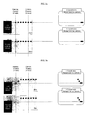
FIG. 2a through 2d illustrates reasons why a position of a making unit needs to be corrected according to the meandering of a film, -
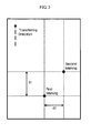
FIG. 3 illustrates a first marking marked by a first marking means and a second marking marked by a second marking means in the present invention, -
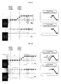
FIG. 4a, 4b and4c show methods for calculating a meandering distance and a meandering angle by a calculating unit of the present invention when a direction of a film is rotated at a certain angle from a transferring direction of the film, -
FIG. 5 shows a transferring direction of a film according to the present invention, -
FIG. 6 shows a meandering control device according to an example of the present invention, -
FIG. 7 illustrates a meandering distance and a meandering angle, -
FIG. 8a and8b show traces of the marks by the first and second marking means which are recognized by a recognizing unit, and 2-dimensional block matrix formed by dividing the marking data into block according to the recognized coordinates, -
FIG. 9 illustrates a method for separating first markings and second markings from noises, -
FIG. 10a and 10b illustrate methods for calculating a meandering distance and a meandering angle according to a computing unit of the present invention, -
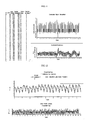
FIG. 11 shows a result of generating correction signal for adjusting positions of a pattern forming equipment and a second marking means based on the computed meandering distance and the meandering angle, -
FIG. 12 shows a result of controlling meandering according to the experiment of the present invention, -
FIG. 13 shows an example for controlling meandering according to the present invention, and -
FIG. 14a and14b shows a method for calculating a meandering distance L. - The present invention relates to a control device for preventing meandering of patterns for use in a patterned film manufacturing device which comprises a film transferring equipment and a pattern forming equipment, comprising: a marking unit that forms markings on a predetermined reference position on the film, the predetermined reference position being positioned using the film transferring equipment as a reference; a recognizing unit, located at the rear of the marking unit, that recognizes positions of the markings on the film; a computing unit that computes an amount of meandering based on differences between the reference position and the recognized positions of the markings; a control unit that generates a correction signal for correcting positions of the marking unit and the pattern forming equipment corresponding to the computed the amount of meandering; and a correction unit that receives the correction signal and corrects positions of the marking unit and the pattern forming equipment based on the received correction signal.
- Hereinafter, the present invention is described in detail.
- In the present invention, meandering of a pattern includes every cases in which a central line of a film transferring equipment and a track of an arbitrary point on a film are not parallel to each other (refer to
FIG. 7 .) The amount of the meandering can be arithmetically denoted using a meandering distance L and a meandering angle θ. For example, if a central axis of a rolled film moves a certain amount of distance in a lateral direction (a direction perpendicular to a transferring direction of the film), the meandering distance L is same as the amount of moving distance of the rolled film and the meandering angle θ is 0°. - Two basic principles for controlling meandering of a pattern on a film in the present invention are as follows.
- (1) When meandering (i.e., movement of a central axis of a film and/or change in a transferring direction of the film) is occurred between a marking unit and a recognizing unit, the recognizing unit recognizes that markings marked by the marking unit has moved in a meandering direction (i.e., a direction where the central axis has moved or changed transferring direction) by the amount of the movement of the central axis or the amount of change in the transferring direction.
- (2) When meandering is occurred before forming markings on a film, the markings are formed in the opposite direction of a meandering direction (i.e., a direction where the central axis has moved or changed transferring direction) by the amount of the movement of the central axis or the amount of change in the transferring direction, when seen from the film.
-
FIG. 2 shows the above-mentioned principles.FIG. 2 illustrates cases including a marking unit which has a fixed first marking means and an adjustable second marking means. - As shown in
FIG. 2a , when meandering is not occurred, a recognizing unit recognizes that markings are formed at their normal position by the marking unit. - As shown in
FiG. 2b , when meandering is occurred, patterns on the film gradually move to one side due to the meandering and the recognizing unit recognizes the moving. However, because the position of the marking unit does not move, the markings formed by the marking unit gradually move to the other side of the film due to the relative position between the marking unit and the film. This can be corrected by moving the position of the marking unit and the pattern forming equipment according to the amount of the meandering. - As shown in
FIG. 2c , when the meandering is stabilized, the recognizing unit recognizes that the markings which have been marked before correcting positions of the marking unit and the pattern forming equipment move to the one side and then the other side. On the other hand, markings which have been marked after adjusting positions of the marking unit and the pattern forming equipment are recognized to move to one side in accordance with the moving of the film and keep the moved position. - Finally, as shown in
FIG. 2d , if the positions of the marking unit and the pattern forming equipment are not corrected according to the meandering, the recognizing unit recognizes that the markings have returned to the original position while the central axis of the film still deviates from the original position. Moreover, in this case, it is impossible to form the pattern on the film correctly because the borders of the patterns overlap each other. - To solve the above-mentioned problem (being unable to recognize the deviation of the central axis of a film), a meandering control device according to the present invention is configured to move positions of a marking unit and a pattern forming equipment in accordance with meandering of a film.
- The control device for preventing meandering of patterns of the present invention is described in detail below.
- The control device is used for a patterned film manufacturing device including a film transferring equipment and a pattern forming equipment.
- An example of the patterned film may be a patterned retarder for implementing 3-dimensional images. The pattern forming equipment is a means for forming patterns on a film. For example, the pattern forming equipment may be an exposure apparatus including a light source and mask, or a roll. A patterned axis of the mask or the roll may be perpendicular to the unrolling direction of the film.
- The control device of the present invention can be used when forming patterns on a sheet-typed film, however, it is more advantageous when used for continuously forming patterns on a roll-typed film.
- The control device of the present invention includes a marking unit that forms markings on a film.
- A reference position of the marking unit is determined using a position of a fixed film transferring equipment as a reference, so that it can form markings on a fixed point regardless of the meandering.
- The marking unit is not limited to any specific type, so any marking means that can form markings which can be detected or recognized by a recognizing unit on the film which is used for a display apparatus such as LCD, etc., while not damaging the film. However, it is preferable to use a laser generator as the marking unit (when the marking unit includes a first marking means and a second marking means, both can be laser generators) for more accurate measurement and control.
- The marking unit can be configured to include one or more marking means.
- When the marking unit includes one marking means, the marking unit can recognize and compute meandering of patterns which is caused by a lateral movement of a central axis of the film, etc., that is, movement of the patterns in a direction perpendicular to a transferring direction. In this case, a meandering distance L can be computed using a method which is described below, and a meandering angle θ is 0°.
- When the marking unit includes two or more marking means, it is possible to compute every types of meandering. The specific method for computing a meandering distance L and a meandering angle θ using the two or more marking means will be described below.
- The two or more marking means may include a first marking means, and a second marking means which is located at a distance d1 in a transferring direction of the film and a distance d2 in the direction perpendicular to the transferring direction of the film from the first marking means (d2 can be zero.) An example of shapes of markings which is formed by the above-described marking unit is shown in
FIG. 3 . - Moreover, the marking unit may further include a means for adjusting distance between the first marking means and the second marking means while forming markings, and in some cases, a position of either the first marking means or the second marking means can be fixed.
- When the marking unit includes two or more marking means, each of the marking means may form markings with different shapes or colors so that each of the markings can be easily distinguished each other or from noises.
- When meandering is not occurred, the markings draw a straight dotted line. When meandering is occurred, the markings draw a line, for example, as shown in
FIG. 2b . The shape of the line can be affected by the distance and angle of the meandering or the transferring speed of the film. The line is recognized by the recognizing unit which will be described below. - The control device according to the present invention includes a recognizing unit located at the rear of the marking unit.
- The recognizing unit is located at the rear of the marking unit (a transferring direction of the film) and recognizes positions of the markings as the film is transferred to a recognition area (i.e., an area where a camera module can capture images if the recognizing unit includes a camera module.)
- In the present invention, the transferring direction means a direction perpendicular to a central axis of a rolled film as shown in
FIG. 5 . The transferring direction is parallel to a machine direction of the film when meandering is not occurred. - The recognizing unit may include one or more recognition areas. According to the number of the recognition areas, the markings which are formed by the first marking means and the second marking means can be recognized simultaneously or respectively.
- Any recognizing or means which can recognize or detect markings on the film and calculate positions or coordinates of the markings may be used as the recognizing unit of the present invention. For example, the recognizing unit may include a camera module that captures images including the markings of the film, and a computer device that stores the captured images and calculates positions of the markings from the captured images.
- When a high resolution vision system which can recognize the markings with diameters of some tens of micrometers is used, it is possible to measure changes in positions of the markings more precisely and to control the meandering more accurately. For example, it is preferable to use a camera module which has a resolution with dimensions on the micrometer level, for example less than ten micrometers.
- The recognizing unit may further include a means that distinguishes noises from the markings. The means is especially useful when the marking unit includes a laser generator because it can prevent foreign substances due to the laser or dusts from being detected as markings.
- Further, for minimize errors due to a shape of the marking, it is preferable to recognize boundaries of each markings and recognize coordinates of centers of the markings as the positions of the markings.
- The control device of the present invention includes a computing unit.
- The computing unit is configured to compute meandering of patterns by a comparison between a known reference position which is determined based on the film transferring equipment as a reference and positions of the markings which are recognized by the recognizing unit.
-
FIG. 14 shows methods for calculating a meandering distance L. -
FIG. 14a illustrates an embodiment that the marking unit includes one marking means. In this case,markings -
FIG. 14b illustrates an embodiment that the marking unit includes a first marking means, and a second marking means located at a distance d1 in a transferring direction of the film and a distance d2 in the direction perpendicular to the transferring direction of the film from the first marking means. - In this case, markings 1-1/2-1, 1-2/2-2, 1-3/2-3, 1-4/2-4 are formed in order as the film progresses (1-A denotes a marking formed by the first marking means, and 1-B denotes a marking formed by the second marking means, where A and B are integers between 1 and 5.) For example, when the recognition area of the recognizing unit is arranged perpendicular to the transferring direction, the recognizing unit recognizes the markings 1-1 and 2-3 at the same time, and then recognizes 1-2 and 2-4. When the central axis of the film moves to the right after 1-4 and 2-4 are formed, the fifth markings deviate from their reference positions by the distance L and are formed in positions denoted as 1-5 and 2-5 in the drawing.
- The computing unit computes a meandering distance L by computing the distance x between 1-3 and 2-5 which are recognized by the recognizing unit and subtracting x from d2 (i.e., the distance between the first and the second marking means in a direction perpendicular to the transferring direction.) If d2 - x is a positive number, it means that the film deviates to the right from the transferring direction, and if d2 - x is negative, the film deviates to the left.
-
FIG. 4 shows methods for calculating a meandering angle θ. - In order to calculate the meandering angle θ, the marking unit needs to have two or more marking means. When the marking unit includes a first marking means and a second marking means located at a distance d1 in a transferring direction of the film and a distance d2 in the direction perpendicular to the transferring direction of the film from the first marking means as shown in
FIG. 14b , the meandering angle θ can be calculated using the distance between the reference position of the marking unit and actual marking position, d1 and d2. -
FIG. 4a illustrates an example without meandering. In this case, the recognized distances between markings marked by the first marking means and the second marking means are same as d2. The meandering angle θ can be calculated using Formula 1 (d1 is a known value.)
-
FIG. 4b illustrates an example when meandering is occurred to the left from the transferring direction. A first marking (a marking marked by the first marking means) which is marked first moves at a left meandering angle θ to the position where the second marking (a marking marked by the second marking means) is formed. In this case, distances between markings formed by the first marking means and the second marking means get closer as the film progresses. The recognizing unit recognizes the first marking and the second marking, and the meandering angle θ can be calculated usingFormula 2. InFormula 2, A represents a mechanically decided distance between the first and the second marking means (or a distance between the first marking and the second marking where there is no meandering), and α is a changed value of ▲ as a result of the meandering. The α is denoted with the minus sign "-" (i.e., -α) inFIG. 4b andFormula 2 because the distance between the markings gets closer than ▲ inFIG. 4b due to the meandering.
-
FIG. 4c illustrates an example when the meandering is occurred to the right from the transferring direction. A first marking (a marking marked by the first marking means) which is marked first moves at a right meandering angle θ to the position where the second marking (a marking marked by the second marking means) is formed. In this case, distances between markings formed by the first marking means and the second marking means grow apart as the film progresses. The recognizing unit recognizes the first marking and the second marking, and the meandering angle θ can be calculated usingFormula 3. InFormula 3, ▲ represents a mechanically decided distance between the first and the second marking means (or a distance between the first marking and the second marking where there is no meandering), and α is a changed value of ▲ as a result of the meandering. The α is denoted with the plus sign "+" (i.e., +α) inFIG. 4c andFormula 3 because the distance between the markings grows farther than ▲ inFIG. 4c due to the meandering.
- The first and the second marking means are preferable to be arranged on a straight line perpendicular to a pattern mask (or pattern roll) of the pattern forming equipment.
- The calculated meandering angle θ is used to correct the position of the pattern forming equipment. At the same time, the position of the first marking means (the leading marking means) is adjusted by α in the direction perpendicular to the transferring direction.
- The computing unit may further include a means that periodically adds up the amount of meandering (i.e., the meandering distance L, the meandering angle θ, or both.) In this case, the control unit which is described below can be configured to generate a correction signal only when the added up amount is greater than a predetermined threshold value.
- The control device of the present invention includes a control unit that generates a correction signal at least for the marking unit and the pattern forming equipment. The control unit generates a correction signal for correcting positions of the marking unit and the pattern forming equipment corresponding to the computed amount of meandering of patterns by the computing unit.
- The control unit may generate the correction signal corresponding to the amount of the meandering of the patterns (i.e., the meandering distance L, the meandering angle θ, or both) whenever meandering is recognized. Or, the control unit may generate the correction signal periodically corresponding to the added up amount of meandering (i.e., the added up meandering distance L, the added up meandering angle θ, or both). Or, the control unit may generate the correction signal only when the added up amount is greater than predetermined threshold value.
- For example, the control unit may generate the correction signal when the added up meandering distance is greater than 20 µm. Or, for example, the control unit may generate the correction signal when the added up meandering angle is greater than 0.5°
- When necessary, the control unit may further generate an additional correction signal for adjusting positions of other components which are needed to be adjusted according to the amount of the meandering, such as the recognizing unit or a cutting means of the film, etc.
- The control unit may generate and transmit a correction signal for a part of the marking unit. For example, when the marking unit includes a first marking means and the second marking means, the control unit may generate a correction signal for either the first marking means or the second marking means or both. Or, when the first marking unit is adjustable while the second marking unit is fixed, the control unit may generate a correction signal only for the first marking means.
- The control device of the present invention includes a correction unit that receives the correction signal and corrects or adjusts positions of the marking unit and the pattern forming equipment based on the received correction signal before forming patterns on the film.
- The correction signal may be a signal for moving the marking unit and the pattern forming equipment by a certain distance, or rotating the marking unit and the pattern forming equipment by a certain angle, or both.
- Therefore, correcting or adjusting positions of the marking unit and the pattern forming equipment means to move the marking unit and the pattern forming equipment by a certain distance, or rotate the marking unit and the pattern forming equipment by a certain angle, or both.
- As mentioned above, the position of the marking unit is adjusted along with the position of the pattern forming equipment so that the control device of the present invention can recognizes the normal state (i.e., a state without meandering) when the meandering goes back to normal. Therefore, according to the present invention, it is possible to solve the problem being unable to form uniform patterns because a part of the boundary of the pattern is overlapped.
- The present invention may be configured to correct the position of the pattern forming equipment before forming patterns.
- The control device of the present invention may include an initializing unit that sets corrected positions of the pattern forming equipment and the marking unit as a new reference position after positions of the pattern forming equipment and the marking unit are corrected by the correction unit.
- A meandering control method which is executed on the control device of the present invention may include, for example, a step for periodically forming a first marking and a second marking using a first marking means and a second marking means which are arranged in respectively predetermined positions, a step for periodically recognizing the first marking and the second marking and calculating a distance between the first marking and the second marking, a step for calculating and adding up a meandering distance and a meandering angle using the distance between the first marking and the second marking, and a reference distance between the first marking and the second marking, a step for generating correction signal for correcting at least one of the positions of the pattern forming equipment, the first marking means, or the second marking means when the added up meandering distance or the meandering angle is greater than predetermined values, and a step for receiving the correction signal and correcting at least one of the positions of the pattern forming equipment, the first marking means, or the second marking means.
- The control method of the present invention includes steps for moving the marking unit and the pattern forming equipment by a certain distance, or rotating the marking unit and the pattern forming equipment by a certain angle, or both.
- The control method of the present invention is preferably as shown in
FIG. 13 . - The control device of the present invention can be used single-handedly for effectively controlling meandering of patterns on a film, however, it is more preferable to use an edge position controller (EPC) in combination with the control device.
- Hereafter, examples are provided for ease of understanding the present invention. However, the following embodiments are provided only as examples of the present invention and it will be readily apparent to one skilled in the art that varying substitutions and modifications may be made to the invention disclosed herein without departing from the scope and spirit of the invention and that such modifications and variations are considered to be within the scope of this invention as defined by the appended claims.
-
FIG. 6 illustrates an exemplary control device according to the present invention. - As shown in
FIG. 6 , a marking unit includes a first marking means and a second marking means. Linear lasergenerators having width 15±3µm are used as the first and the second marking means. The laser generators are arranged near the right border of the rolled film and the distance between the first marking means and the second marking means is 100mm in the transferring direction of the film (d1 = 100mm) and 2mm in the direction perpendicular to the transferring direction of the film (d2 = 2mm), therefore, when the meandering angle θ is changed by 0.1°, d2 increases or decreases by 177µm [100*tan(0.1)µm]. - The recognizing unit includes a camera module which has a resolution with dimensions on the 3.0µm and a computer device that can calculate positions of the markings from the captured images from the camera module. The camera module is arranged at the rear of the second marking unit at a distance of 750mm.
- An exposure apparatus and a mask are arranged at the rear of the recognizing unit, two fixed marks are arranged at each side of the mask to check alignment of the mask, and another camera module is installed on the mask for recognizing the fixed marks. The distance between the fixed marks and the other camera module is 45mm.
- Moreover, the computing unit is configured to compute the meandering distance L and the meandering angle θ using predetermined values of d1 and d2, and the distance between the first and the second marking means which is recognized by the recognizing unit.
- The control unit is designed to transmit a correction signal to the pattern forming equipment and the marking unit based on the meandering distance L and the meandering angle θ every 20mm of the progress of the film.
- Whether the meandering occurs or not is checked in the cases of line speeds of 3m/min. and 5m/min., and tensions of the film of 130N, 200N, and 250N.
- As the result of the experiment, as shown in Table 1, considerable meandering occurs in every case regardless of the edge position controller (ETC).
[Table 1] Line speed (m/min.) Tension (N) EPC Meandering angle (deg) Maximum movement of the center in a unit section (um) 1 10 100 1000 3 130 on +/- 0.06 5 17 48 64 off +/- 0.06 6 17 68 125 200 on +/- 0.06 5 11 49 58 off +/- 0.06 3 9 39 52 250 on +/- 0.05 3 11 19 33 off +/- 0.06 13 20 48 72 5 130 on +/- 0.10 13 28 55 95 off +/- 0.15 16 64 123 182 200 on +/- 0.13 12 35 68 101 off +/- 0.15 71 71 75 87 250 on +/- 0.13 51 59 61 78 off +/- 0.15 45 48 92 105 - A simulation for controlling meandering of the film using the control device according to the example above was carried on in the case of the line speed of 5m/min. and the tensions of the film of 200N. EPC is not applied and the threshold value of the meandering is 10 µm.
- At first, eliminate noises and extract traces of the marks by the first and second marking means from marking data shown in
FIG. 8a which are recognized by the recognizing unit. Specifically, form a 2-dimensional block matrix by dividing the marking data into block according to the recognized coordinates, segment linked blocks into a blob and eliminates blobs with the size of less than 3000µm from the marking data as noises, and investigate major linking curves and separate the first marking trace (the upper line) and the second marking trace (the lower line) (refer toFIG. 9 .) - When F denotes the whole block set, and S1, S2, ..., Sn respectively denote each of the block including F, they satisfy the following
Formula 4.
- The computing unit computes the meandering distance L and the meandering angle θ based on the data regarding the first marking and the second marking.
- The meandering angle θ is calculated using
Formula 5 for each of the sections as shown inFIG. 11 . The distance d between the first marking and the second marking is calculated usingFormula 5 and the angle θ is obtained using the tangent value of d (tan(d)). InFormula 5, d3 is a distance between a first laser generator and a second laser generator in a transferring direction, and d4 is a distance between the first laser generator and the second laser generator in a direction perpendicular to the transferring direction. In the simulation described above, d3 is 100mm and d4 is 2mm.
- The meandering distance L is calculated using
Formula 6 with coordinates of the second markings for each of the sections as shown inFIG. 11 . InFormula 6, x1, ..., xn are coordinates in the direction perpendicular to the transferring direction.
- The control unit transmits the correction signal when the meandering distance L is greater than the predetermined value of 10 µm, and the corrected position is set as a new reference position. In
FIG. 11 , sections in which the correction signal is transmitted are marked as checked. -
FIG. 12 shows a result of controlling meandering according to the experiment of the present invention.
Claims (23)
- A control device for preventing meandering of patterns for use in a patterned film manufacturing device which comprises a film transferring equipment and a pattern forming equipment, comprising:a marking unit that forms markings on a predetermined reference position on the film, the predetermined reference position being positioned using the film transferring equipment as a reference;a recognizing unit, located at the rear of the marking unit, that recognizes positions of the markings on the film;a computing unit that computes an amount of meandering based on differences between the reference position and the recognized positions of the markings;a control unit that generates a correction signal for correcting positions of the marking unit and the pattern forming equipment corresponding to the computed the amount of meandering; anda correction unit that receives the correction signal and corrects positions of the marking unit and the pattern forming equipment based on the received correction signal.
- The control device of claim 1, wherein the marking unit comprises a marking means that periodically forms markings on the film.
- The control device of claim 2, wherein the computing unit computes the amount of meandering which is caused by a lateral movement of a central axis of the film (movement of the central axis of the film by a distance L in a direction perpendicular to a transferring direction of the film) based on differences in distances between the reference position of the marking means and the recognized positions of the markings.
- The control device of claim 3, wherein the control unit generates the correction signal for moving positions of the marking unit and the pattern forming equipment by the distance L in a direction perpendicular to the transferring direction of the film.
- The control device of claim 1, wherein the marking unit comprises:a first marking means; anda second marking means, located at a distance d1 in a transferring direction of the film and a distance d2 in the direction perpendicular to the transferring direction of the film, from the first marking means.
- The control device of claim 5, wherein the marking unit further comprises a means that adjusts a distance between the first marking means and the second marking means while the markings are formed.
- The control device of claim 5, wherein a position of either the first marking means or the second marking means is fixed.
- The control device of claim 6 or 7, wherein the computing unit computes a meandering distance L and a meandering angle θ using a difference in distance between a reference position of the first marking means (or the second marking means) and an actual position of marking by the first marking means (or the second marking means), d1, and d2.
- The control device of claim 8, wherein the control unit generates the correction signal for correcting positions of the marking unit and the pattern forming equipment by the distance L and the angle θ.
- The control device of claim 1 or 5, wherein the recognizing unit comprises:a camera module that periodically captures images comprising the markings of the film; anda means that periodically stores the captured images, and calculates coordinates of the markings from the captured images.
- The control device of claim 1 or 5, wherein the recognizing unit further comprises a means that distinguishes noises from the markings.
- The control device of claim 1 or 5, wherein the computing unit further comprises a means that periodically adds up the amount of meandering.
- The control device of claim 12, wherein the amount of meandering comprises a meandering distance L, a meandering angle θ, or both.
- The control device of claim 13, wherein the control unit generates the correction signal when the meandering distance L which is added up by the computing unit is greater than a predetermined threshold value, the meandering angle θ which is added up by the computing unit is greater than a predetermined threshold value, or both of the meandering distance L and the meandering angle θ which are added up by the computing unit are greater than predetermined threshold values.
- The control device of claim 5, wherein the control unit generates a correction signal for either the first marking means or the second marking means.
- The control device of claim 1 or 5, wherein the pattern forming equipment comprises a mask or a roll which is arranged in a direction perpendicular to the transferring direction of the film.
- The control device of claim 1 or 5 further comprises an initializing unit that sets corrected positions of the pattern forming equipment and the marking unit as a reference position after positions of the pattern forming equipment and the marking unit are corrected by the correction unit.
- The control device of claim 1 or 5, wherein the marking unit comprises a laser generation means which can form markings with diameters of some tens of micrometers, and the recognizing unit comprises a high resolution vision system which can recognize the markings with diameters of less than ten micrometers.
- The control device of claim 18, wherein the high resolution vision system recognizes coordinates of centers of the markings as coordinates of the markings for reducing errors due to shapes of the markings.
- The control device of claim 1 or 5, wherein the control unit further generates a correction signal for correcting a position of a cutting means of the film.
- The control device of claim 1 or 5, wherein the recognizing unit is located at the front of the pattern forming equipment and recognizes meandering of the patterns of the film before the patterns are formed on the film.
- A method for controlling meandering of patterns using the control device of claim 1 or 5.
- The method of claim 22, wherein the method uses an edge position controller (EPC) in combination with the control device.
Applications Claiming Priority (2)
| Application Number | Priority Date | Filing Date | Title |
|---|---|---|---|
| KR20110037635 | 2011-04-22 | ||
| KR1020110095852A KR101829308B1 (en) | 2011-04-22 | 2011-09-22 | Controlling device for preventing snaking of patterns of patterned flims |
Publications (2)
| Publication Number | Publication Date |
|---|---|
| EP2514696A2 true EP2514696A2 (en) | 2012-10-24 |
| EP2514696A3 EP2514696A3 (en) | 2015-05-27 |
Family
ID=46298181
Family Applications (1)
| Application Number | Title | Priority Date | Filing Date |
|---|---|---|---|
| EP12002826.1A Withdrawn EP2514696A3 (en) | 2011-04-22 | 2012-04-23 | Controlling device for preventing snaking of patterns of patterned films |
Country Status (6)
| Country | Link |
|---|---|
| US (1) | US9134634B2 (en) |
| EP (1) | EP2514696A3 (en) |
| JP (1) | JP5960485B2 (en) |
| KR (1) | KR101829308B1 (en) |
| TW (1) | TWI556069B (en) |
| WO (1) | WO2012144738A2 (en) |
Families Citing this family (7)
| Publication number | Priority date | Publication date | Assignee | Title |
|---|---|---|---|---|
| KR101634669B1 (en) * | 2014-09-23 | 2016-06-30 | 한국기계연구원 | Apparatus and Method for Snaking of Flexible Film |
| KR20190007748A (en) | 2017-07-13 | 2019-01-23 | 에이치피프린팅코리아 유한회사 | Fusing apparatus and image forming apparatus having the same |
| KR102080346B1 (en) * | 2019-05-29 | 2020-02-24 | 주식회사 시우테크 | High Speed Electrode Nothing System for Secondary Battery |
| KR102283071B1 (en) * | 2020-09-21 | 2021-07-29 | 위더스케미칼 주식회사 | Producing device for shrinkable label filme |
| KR102315950B1 (en) * | 2021-06-30 | 2021-10-22 | (주)신화에프에이 | Apparatus for adjusting serpentine moving of film |
| KR20240082576A (en) | 2022-12-02 | 2024-06-11 | 주식회사 엘지에너지솔루션 | Pouch film supply device for secondary battery |
| KR102703505B1 (en) * | 2024-05-29 | 2024-09-06 | 주식회사 위즈솔루션 | Roll-to-roll patterning apparatus and method |
Citations (1)
| Publication number | Priority date | Publication date | Assignee | Title |
|---|---|---|---|---|
| JP2003337226A (en) | 1996-09-12 | 2003-11-28 | Sharp Corp | Passive polarization-modulating optical element, optical device using the element, and method for producing the element |
Family Cites Families (27)
| Publication number | Priority date | Publication date | Assignee | Title |
|---|---|---|---|---|
| JP3109227B2 (en) * | 1992-03-27 | 2000-11-13 | 凸版印刷株式会社 | Web meandering correction mechanism |
| JPH0867381A (en) * | 1994-08-30 | 1996-03-12 | Mitsubishi Heavy Ind Ltd | Meandering correcting device for web |
| JP3741013B2 (en) * | 2001-09-17 | 2006-02-01 | ウシオ電機株式会社 | Belt-shaped workpiece exposure device with meandering correction mechanism |
| JP2003200385A (en) * | 2001-12-28 | 2003-07-15 | Fuji Photo Film Co Ltd | Web processing device |
| JP2003200384A (en) * | 2001-12-28 | 2003-07-15 | Fuji Photo Film Co Ltd | Web processing device |
| JP2003248113A (en) * | 2002-02-22 | 2003-09-05 | Fuji Photo Film Co Ltd | Web processing device and method for positioning processing heat thereof |
| AU2003296523A1 (en) * | 2002-12-10 | 2004-06-30 | Infineon Technologies Ag | Surface paneling module, surface paneling module arrangement and method for determining the distance of surface paneling modules of the surface paneling module arrangement to at least one reference position, processor arrangement, textile fabric structure and surface paneling structure |
| JP4127664B2 (en) * | 2003-06-30 | 2008-07-30 | 株式会社東芝 | Method for adjusting development processing apparatus |
| US7138919B2 (en) * | 2004-02-23 | 2006-11-21 | Checkpoint Systems, Inc. | Identification marking and method for applying the identification marking to an item |
| JP4328301B2 (en) * | 2004-03-29 | 2009-09-09 | 富士フイルム株式会社 | Exposure apparatus and exposure method |
| JP4768251B2 (en) * | 2004-11-01 | 2011-09-07 | 株式会社東芝 | Semiconductor integrated circuit design method, semiconductor integrated circuit design system, and semiconductor integrated circuit manufacturing method |
| JP5167812B2 (en) * | 2005-07-15 | 2013-03-21 | コニカミノルタアドバンストレイヤー株式会社 | Optical film processing method, optical film processing apparatus, and optical film manufacturing method |
| JP2007072853A (en) * | 2005-09-08 | 2007-03-22 | Renesas Technology Corp | Manufacturing method of electronic device |
| JP2007079318A (en) * | 2005-09-15 | 2007-03-29 | Konica Minolta Opto Inc | Optical element and its marking method, and assembling method for optical unit |
| JP2007093861A (en) * | 2005-09-28 | 2007-04-12 | Renesas Technology Corp | Method for designing mask pattern, and method for manufacturing semiconductor device |
| JP2007101719A (en) * | 2005-09-30 | 2007-04-19 | Mitsumi Electric Co Ltd | Optical waveguide device |
| KR101313948B1 (en) * | 2005-11-04 | 2013-10-01 | 코니카 미놀타 어드밴스드 레이어즈 인코포레이티드 | Cellulosic resin film, process for producing cellulosic resin film, antireflection film, polarizer, and liquid-crystal display |
| US20090169772A1 (en) * | 2005-12-09 | 2009-07-02 | Konica Minolta Opto, Inc. | Retardation film, method for producing retardation film, polarizing plate and liquid crystal display |
| JP2007310209A (en) * | 2006-05-19 | 2007-11-29 | Nsk Ltd | Exposure equipment |
| JP5076441B2 (en) * | 2006-10-20 | 2012-11-21 | 東洋製罐株式会社 | Bag making apparatus and bag manufacturing method |
| KR101034818B1 (en) * | 2009-04-07 | 2011-05-16 | 대한고열공업(주) | Pattern Forming Apparatus and Method of Flexible Sheet |
| JP2010265062A (en) * | 2009-05-13 | 2010-11-25 | Sharp Corp | Sheet conveying apparatus and sheet meandering correction method |
| JP5588223B2 (en) * | 2009-05-26 | 2014-09-10 | 旭化成イーマテリアルズ株式会社 | Defect marking apparatus and defect marking method for wire grid polarizing film |
| JP5293498B2 (en) * | 2009-08-21 | 2013-09-18 | トヨタ自動車株式会社 | Web conveying apparatus and method and battery manufacturing method |
| JP4503689B1 (en) * | 2009-10-13 | 2010-07-14 | 日東電工株式会社 | Method and apparatus for continuous production of liquid crystal display elements |
| JP4503693B1 (en) * | 2009-10-13 | 2010-07-14 | 日東電工株式会社 | Continuous roll of cut-lined optical film laminate in the form of a continuous web, its manufacturing method and manufacturing apparatus |
| JP5424271B2 (en) * | 2010-11-08 | 2014-02-26 | 株式会社ブイ・テクノロジー | Exposure equipment |
-
2011
- 2011-09-22 KR KR1020110095852A patent/KR101829308B1/en not_active Expired - Fee Related
-
2012
- 2012-03-22 WO PCT/KR2012/002059 patent/WO2012144738A2/en not_active Ceased
- 2012-03-28 TW TW101110752A patent/TWI556069B/en not_active IP Right Cessation
- 2012-04-20 JP JP2012096419A patent/JP5960485B2/en not_active Expired - Fee Related
- 2012-04-21 US US13/452,828 patent/US9134634B2/en not_active Expired - Fee Related
- 2012-04-23 EP EP12002826.1A patent/EP2514696A3/en not_active Withdrawn
Patent Citations (1)
| Publication number | Priority date | Publication date | Assignee | Title |
|---|---|---|---|---|
| JP2003337226A (en) | 1996-09-12 | 2003-11-28 | Sharp Corp | Passive polarization-modulating optical element, optical device using the element, and method for producing the element |
Also Published As
| Publication number | Publication date |
|---|---|
| TWI556069B (en) | 2016-11-01 |
| CN102759864A (en) | 2012-10-31 |
| JP5960485B2 (en) | 2016-08-02 |
| KR20120119968A (en) | 2012-11-01 |
| JP2012230380A (en) | 2012-11-22 |
| WO2012144738A2 (en) | 2012-10-26 |
| EP2514696A3 (en) | 2015-05-27 |
| US20120271447A1 (en) | 2012-10-25 |
| KR101829308B1 (en) | 2018-02-20 |
| WO2012144738A3 (en) | 2013-03-07 |
| US9134634B2 (en) | 2015-09-15 |
| TW201303527A (en) | 2013-01-16 |
Similar Documents
| Publication | Publication Date | Title |
|---|---|---|
| US9134634B2 (en) | Control device for preventing meandering of patterns on patterned films | |
| CN107548476B (en) | Method for correcting predetermined cutting paths for cutting sheet metal blanks | |
| US9235135B2 (en) | Exposure apparatus | |
| CN104520055A (en) | Method for cutting sheet metal blank | |
| JPH02500971A (en) | Adjustment control system for webs with variable repeat length sections | |
| JP2013137197A (en) | Laser type thickness measurement system and calibration method therefor | |
| JP2019025718A (en) | Pattern transfer apparatus and pattern transfer method | |
| CN113601040A (en) | Positioning and punching system for glass plate laser drilling machine and its operation method | |
| EP2716457B1 (en) | Print pitch correcting apparatus for plastic film | |
| US10211080B2 (en) | Robot arms and method for aligning substrate with the same | |
| CN112834239B (en) | AEBS offline detection method and system | |
| CN112058920B (en) | Hole type calibration method and calibration system for rolling mill and guide | |
| CN107063057A (en) | A kind of tyre detection device with calibrating block | |
| KR20120062632A (en) | Conveyed amount detecting device for plate-shaped object, cutting device for plate-shaped object, conveyed amount detecting method for plate-shaped object, cutting line making device for plate-shaped object and cutting line making method for plate-shaped object | |
| US12487077B2 (en) | Optical axis adjustment jig and optical axis adjustment method | |
| KR101129643B1 (en) | Movement tracking method of marking apparatus | |
| CN118111359A (en) | A non-contact strip flatness detection device and method | |
| KR102630749B1 (en) | System And Method for Calibration of Electrode During Manufacturing Secondary Battery Cell | |
| CN104191094A (en) | High-precision wafer back etching centering system groove alignment method | |
| CN102759864B (en) | For the control device preventing the pattern on pattern film from bending | |
| KR20130055172A (en) | Substrate aligning unit, substrate processing apparatus having the same and method of processing substrate using the same | |
| US10112422B2 (en) | Method of aligning a first image on a first side of a medium and a second image on a second side of a medium | |
| CN121340801B (en) | Coiled material double-sided alignment printing system | |
| CN110530295B (en) | Tool and method for detecting perpendicularity of motion platform | |
| CN215152920U (en) | Printing alignment structure of annular printing screen |
Legal Events
| Date | Code | Title | Description |
|---|---|---|---|
| PUAI | Public reference made under article 153(3) epc to a published international application that has entered the european phase |
Free format text: ORIGINAL CODE: 0009012 |
|
| AK | Designated contracting states |
Kind code of ref document: A2 Designated state(s): AL AT BE BG CH CY CZ DE DK EE ES FI FR GB GR HR HU IE IS IT LI LT LU LV MC MK MT NL NO PL PT RO RS SE SI SK SM TR |
|
| AX | Request for extension of the european patent |
Extension state: BA ME |
|
| PUAL | Search report despatched |
Free format text: ORIGINAL CODE: 0009013 |
|
| AK | Designated contracting states |
Kind code of ref document: A3 Designated state(s): AL AT BE BG CH CY CZ DE DK EE ES FI FR GB GR HR HU IE IS IT LI LT LU LV MC MK MT NL NO PL PT RO RS SE SI SK SM TR |
|
| AX | Request for extension of the european patent |
Extension state: BA ME |
|
| RIC1 | Information provided on ipc code assigned before grant |
Ipc: G03F 7/20 20060101ALI20150423BHEP Ipc: B65H 23/02 20060101AFI20150423BHEP Ipc: G03F 9/00 20060101ALI20150423BHEP |
|
| STAA | Information on the status of an ep patent application or granted ep patent |
Free format text: STATUS: THE APPLICATION IS DEEMED TO BE WITHDRAWN |
|
| 18D | Application deemed to be withdrawn |
Effective date: 20151128 |