EP2511999B1 - Umkonfigurierbare Leistungswandler, Systeme und Anlagen - Google Patents
Umkonfigurierbare Leistungswandler, Systeme und Anlagen Download PDFInfo
- Publication number
- EP2511999B1 EP2511999B1 EP12159377.6A EP12159377A EP2511999B1 EP 2511999 B1 EP2511999 B1 EP 2511999B1 EP 12159377 A EP12159377 A EP 12159377A EP 2511999 B1 EP2511999 B1 EP 2511999B1
- Authority
- EP
- European Patent Office
- Prior art keywords
- power
- converter
- storage device
- energy storage
- electrical energy
- Prior art date
- Legal status (The legal status is an assumption and is not a legal conclusion. Google has not performed a legal analysis and makes no representation as to the accuracy of the status listed.)
- Active
Links
Images




Classifications
-
- H—ELECTRICITY
- H02—GENERATION; CONVERSION OR DISTRIBUTION OF ELECTRIC POWER
- H02J—ELECTRIC POWER NETWORKS; CIRCUIT ARRANGEMENTS OR SYSTEMS FOR SUPPLYING OR DISTRIBUTING ELECTRIC POWER; SYSTEMS FOR STORING ELECTRIC ENERGY
- H02J3/00—Circuit arrangements for AC mains or AC distribution networks
- H02J3/28—Arrangements for balancing of the load in networks by storage of energy
- H02J3/32—Arrangements for balancing of the load in networks by storage of energy using batteries or super capacitors with converting means
-
- H—ELECTRICITY
- H02—GENERATION; CONVERSION OR DISTRIBUTION OF ELECTRIC POWER
- H02J—ELECTRIC POWER NETWORKS; CIRCUIT ARRANGEMENTS OR SYSTEMS FOR SUPPLYING OR DISTRIBUTING ELECTRIC POWER; SYSTEMS FOR STORING ELECTRIC ENERGY
- H02J3/00—Circuit arrangements for AC mains or AC distribution networks
- H02J3/38—Arrangements for feeding a single network from two or more generators or sources in parallel; Arrangements for feeding already energised networks from additional generators or sources in parallel
- H02J3/381—Dispersed generators
-
- H—ELECTRICITY
- H02—GENERATION; CONVERSION OR DISTRIBUTION OF ELECTRIC POWER
- H02S—GENERATION OF ELECTRIC POWER BY CONVERSION OF INFRARED RADIATION, VISIBLE LIGHT OR ULTRAVIOLET LIGHT, e.g. USING PHOTOVOLTAIC [PV] MODULES
- H02S40/00—Components or accessories in combination with PV modules, not provided for in groups H02S10/00 - H02S30/00
- H02S40/30—Electrical components
- H02S40/38—Energy storage means, e.g. batteries, structurally associated with PV modules
-
- H—ELECTRICITY
- H02—GENERATION; CONVERSION OR DISTRIBUTION OF ELECTRIC POWER
- H02J—ELECTRIC POWER NETWORKS; CIRCUIT ARRANGEMENTS OR SYSTEMS FOR SUPPLYING OR DISTRIBUTING ELECTRIC POWER; SYSTEMS FOR STORING ELECTRIC ENERGY
- H02J2101/00—Supply or distribution of decentralised, dispersed or local electric power generation
- H02J2101/20—Dispersed power generation using renewable energy sources
- H02J2101/22—Solar energy
- H02J2101/24—Photovoltaics
-
- H—ELECTRICITY
- H02—GENERATION; CONVERSION OR DISTRIBUTION OF ELECTRIC POWER
- H02J—ELECTRIC POWER NETWORKS; CIRCUIT ARRANGEMENTS OR SYSTEMS FOR SUPPLYING OR DISTRIBUTING ELECTRIC POWER; SYSTEMS FOR STORING ELECTRIC ENERGY
- H02J2101/00—Supply or distribution of decentralised, dispersed or local electric power generation
- H02J2101/20—Dispersed power generation using renewable energy sources
- H02J2101/22—Solar energy
- H02J2101/24—Photovoltaics
- H02J2101/25—Photovoltaics involving maximum power point tracking control for photovoltaic sources
-
- H—ELECTRICITY
- H02—GENERATION; CONVERSION OR DISTRIBUTION OF ELECTRIC POWER
- H02J—ELECTRIC POWER NETWORKS; CIRCUIT ARRANGEMENTS OR SYSTEMS FOR SUPPLYING OR DISTRIBUTING ELECTRIC POWER; SYSTEMS FOR STORING ELECTRIC ENERGY
- H02J3/00—Circuit arrangements for AC mains or AC distribution networks
- H02J3/38—Arrangements for feeding a single network from two or more generators or sources in parallel; Arrangements for feeding already energised networks from additional generators or sources in parallel
- H02J3/46—Controlling the sharing of generated power between the generators, sources or networks
-
- Y—GENERAL TAGGING OF NEW TECHNOLOGICAL DEVELOPMENTS; GENERAL TAGGING OF CROSS-SECTIONAL TECHNOLOGIES SPANNING OVER SEVERAL SECTIONS OF THE IPC; TECHNICAL SUBJECTS COVERED BY FORMER USPC CROSS-REFERENCE ART COLLECTIONS [XRACs] AND DIGESTS
- Y02—TECHNOLOGIES OR APPLICATIONS FOR MITIGATION OR ADAPTATION AGAINST CLIMATE CHANGE
- Y02E—REDUCTION OF GREENHOUSE GAS [GHG] EMISSIONS, RELATED TO ENERGY GENERATION, TRANSMISSION OR DISTRIBUTION
- Y02E10/00—Energy generation through renewable energy sources
- Y02E10/50—Photovoltaic [PV] energy
- Y02E10/56—Power conversion systems, e.g. maximum power point trackers
-
- Y—GENERAL TAGGING OF NEW TECHNOLOGICAL DEVELOPMENTS; GENERAL TAGGING OF CROSS-SECTIONAL TECHNOLOGIES SPANNING OVER SEVERAL SECTIONS OF THE IPC; TECHNICAL SUBJECTS COVERED BY FORMER USPC CROSS-REFERENCE ART COLLECTIONS [XRACs] AND DIGESTS
- Y02—TECHNOLOGIES OR APPLICATIONS FOR MITIGATION OR ADAPTATION AGAINST CLIMATE CHANGE
- Y02E—REDUCTION OF GREENHOUSE GAS [GHG] EMISSIONS, RELATED TO ENERGY GENERATION, TRANSMISSION OR DISTRIBUTION
- Y02E70/00—Other energy conversion or management systems reducing GHG emissions
- Y02E70/30—Systems combining energy storage with energy generation of non-fossil origin
Definitions
- the present disclosure relates to power converters and systems, and more particularly to reconfigurable power converters and systems.
- Examples of solar and electric power converter systems are disclosed in U.S. Patent Nos. 7,072,194 ; 6,914,418 and 6,590,793 and in U.S. Patent Application Publication No. 2010/0008119 .
- Examples of battery charging using solar or photovoltaic panels and maximum power point tracking (MPPT) are disclosed in U.S. Patent Nos. 7,834,580 ; 6,914,418 and 6,057,665 .
- WO2009155445 A2 describes a power system provided with only one possible electrical connection between a DC power source and an energy storage device.
- the present invention defines a reconfigurable power system as claimed.
- Reconfigurable power systems include a DC power source, an electrical energy storage device, an AC power grid connection, a first power converter, and a second power converter.
- the first power converter is configured to selectively couple two or more of the DC power source, the electrical energy storage device, and the AC power grid connection.
- the second power converter is configured to selectively couple the electrical energy storage device to at least one of the DC power source and the first power converter.
- the second power converter is configured as a DC-DC converter.
- reconfigurable power converters may include a power source connection configured to couple with a DC power source, a storage device connection configured to couple with an electrical energy storage device, a grid connection configured to couple with an AC power grid, a first power converter, and a second power converter.
- the first power converter may be configured to selectively couple two or more of the power source connection, the storage device connection, and the grid connection.
- the first power converter may be configured as a DC-DC converter when coupling the power source connection to the storage device connection, a DC-AC inverter when coupling at least one of the power source connection and the storage device connection to the grid connection, and an AC-DC converter when coupling the grid connection to the storage device connection.
- the second power converter may be configured to selectively couple the storage device connection to at least one of the power source connection and the first power converter.
- the second power converter may be configured as a DC-DC converter.
- methods of operating reconfigurable power systems may include configuring a first power converter as a DC-DC converter and coupling the DC power source to the electrical energy storage device therewith, configuring the first power converter as a DC-AC inverter and coupling the DC power source to the AC power grid connection therewith while a second power converter, which may be configured as a DC-DC converter, couples the electrical energy storage device to the DC power source and the first power converter, and configuring the first power converter as a DC-AC inverter and coupling the electrical energy storage device to the AC power grid connection therewith.
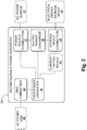
- the power system 20 includes a DC power source 22, an electrical energy storage device 24, a connection to an AC power grid or AC power grid connection 26, a first power converter 28, and an auxiliary or second power converter 29.
- the DC power source 22 may include any DC source, such as an intermittent or non-base load source.
- the DC power source may include at least one solar or photovoltaic (PV) cell.
- at least a portion of the DC source may include other intermittent power sources such as wind or tidal power.
- some possible intermittent power sources, such as wind and tidal power may need to be converted to DC before use with the reconfigurable power system 20.
- the electrical energy storage device 24 may include any suitable combination of devices or structures capable of storing electrical energy.
- Nonexclusive illustrative examples of such devices include, without limitation, electrochemical cells or batteries, capacitors, supercapacitors, flywheels, or the like.
- the first power converter 28 is configured to selectively couple two or more of the DC power source 22, the electrical energy storage device 24, the AC power grid connection 26, and the second power converter 29.
- the second power converter 29 is configured to selectively couple the electrical energy storage device 24 to at least one of the DC power source 22 and the first power converter 28.
- the second power converter 29 is configured as a DC-DC converter. As will be more fully set out below, the second power converter 29 may be used in some examples where the electrical energy storage device 24 is being charged and/or discharged.
- Either or both of the first power converter 28 and the second power converter 29 may include at least one switching element or device.
- the switching element or device may include at least one semiconductor switching device, such as a power transistor, a power MOSFET, an insulated gate bipolar transistor (IGBT), a gate turn-off thyristor (GTO), or the like.
- IGBT insulated gate bipolar transistor
- GTO gate turn-off thyristor
- the first power converter 28 may be configured to operate in a selected one of at least three modes.
- the first power converter 28 may be configured to selectively operate or function as a DC-AC inverter, a DC-DC converter, or an AC-DC converter.
- the first power converter 28 may be configured to function as a DC-AC inverter when coupling the DC power source 22 and/or the electrical energy storage device 24 to the AC power grid connection 26, such as to deliver power from the DC power source, the electrical energy storage device, or both to the AC power grid.
- the electrical energy storage device may be coupled to the DC power source and to the first power converter by way of the second power converter 29.
- the first power converter 28 may be configured to function as a DC-DC converter when coupling the DC power source 22 to the electrical energy storage device 24, such as to charge the electrical energy storage device.
- the first power converter 28 may be configured to function as an AC-DC converter when coupling the AC power grid connection 26 to the electrical energy storage device 24, such as to charge the electrical energy storage device from the AC power grid.
- the reconfigurable power converter 30 includes a power source connection 32, a storage device connection 34, a grid connection 36, a first power converter 38, and an auxiliary or second power converter 39.
- the power source connection 32 may be configured to couple with a DC power source 22
- the storage device connection 34 may be configured to couple with an electrical energy storage device 24
- the grid connection 36 may be configured to couple with an AC power grid 40.
- the first power converter 38 which may include at least one semiconductor switching device, is configured to selectively couple two or more of the power source connection 32, the storage device connection 34, the grid connection 36, and the second power converter 39.
- the first power converter 38 may be selectively configured as, for example, a DC-DC converter, a DC-AC inverter or an AC-DC converter.
- the first power converter 38 when coupling the power source connection 32 to the storage device connection 34, the first power converter 38 may be configured as a DC-DC converter.
- the first power converter 38 When coupling the grid connection 36 to at least one of the power source connection 32, the storage device connection 34 and the second power converter 39, the first power converter 38 may be configured as a DC-AC inverter.
- the power converter When coupling the grid connection 36 to the storage device connection 34, the power converter may be configured as an AC-DC converter.
- the second power converter 39 which is configured as a DC-DC converter and may include at least one semiconductor switching device, is configured to selectively couple the storage device connection 34 to at least one of the power source connection 32 and the first power converter 38.
- the reconfigurable power converter 30 may include a current-limiting structure or device 42, such as a resistor.
- the current-limiting structure or device 42 may be configured to selectively limit inrush current to an electrical energy storage device 24 that is coupled with the storage device connection 34.
- FIGs. 3-6 illustrate further nonexclusive illustrative examples of reconfigurable power systems.
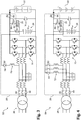
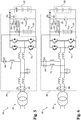
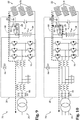
- a 3-phase asymmetric reconfigurable power system 52 is shown in Fig. 3
- a 3-phase symmetric reconfigurable power system 54 is shown in Fig. 4
- a single-phase asymmetric reconfigurable power system 56 is shown in Fig. 5
- a single-phase symmetric reconfigurable power system 58 is shown in Fig. 6 .
- each of the reconfigurable power systems 52, 54, 56, 58 includes a DC power source 22, an electrical energy storage device 24, an AC power grid connection 26, a first power converter 28 with a plurality of converter circuits 70, and a second power converter 29.
- the power converters 28 of the reconfigurable power systems 52 may include a plurality of switches 62, 64, 66, 68, 69.
- the power converters 28 may optionally include at least one inductor 72 on the circuit path used to charge the electrical energy storage device 24 from the DC power source 22, as will be set out below.
- the asymmetric configuration may permit a reduction in manufacturing cost and/or physical size of the power converter.
- the wiring would be simplified, the switch 64 would only need to include a single switch, and only a single inductor 72 would be needed.
- the symmetric configuration may permit more efficient utilization of the converter circuits 70 within the power converter and/or equalize the losses across all of the converter circuits 70, such as by equalizing the losses on the semiconductor switches in the power converter when using the DC power source to charge the battery, as will be set out below.
- the reconfigurable power system 76 includes a DC power source 22, an electrical energy storage device 24, an AC power grid connection 26, a first power converter 28, and a second power converter 29.
- the DC power source 22 of the reconfigurable power system 76 may include a plurality of photovoltaic cells 78, and the electrical energy storage device 24 may include a battery.
- the switches 64, 68 are closed, while the switches 62, 66, 69 are open, such that the first power converter 28 of the reconfigurable power system 76 is coupling the plurality of photovoltaic cells 78 of the DC power source 22 to the electrical energy storage device 24, with a power flow as generally suggested by the arrow 82.
- the first power converter 28 is configured to function as a DC-DC converter such that the photovoltaic cells 78 charge the electrical energy storage device 24.
- the first power converter 28 may perform maximum power point tracking (MPPT) with the photovoltaic cells 78. Under maximum power point tracking, the first power converter 28 attempts to function as a substantially optimal electrical load for the photovoltaic cells in order to extract a relatively high level of power from the photovoltaic cells. In some examples, the level of power extracted from the photovoltaic cells during maximum power point tracking may be near the maximum or even the maximum power available from the photovoltaic cells.
- MPPT maximum power point tracking
- the switches 66, 68, 69 are closed, while the switches 62, 64 are open, such that the first power converter 28 of the reconfigurable power system 76 is coupling the plurality of photovoltaic cells 78 of the DC power source 22 to the electrical energy storage device 24 and to the AC power grid connection 26, with the electrical energy storage device 24 being coupled to the plurality of photovoltaic cells 78 and to the first power converter 28 by way of the second power converter 29.
- the first power converter 28 is configured to function as a DC-AC inverter such that the photovoltaic cells 78 deliver power to the AC power grid through the first power converter 28 while charging the electrical energy storage device 24 through the second power converter 29, with a power flow as generally suggested by the arrows 84.
- the first power converter 28 and/or the second power converter 29 may perform maximum power point tracking with the photovoltaic cells 78.
- the first power converter 28 is able to perform maximum power point tracking for the photovoltaic cells when the reconfigurable power system 76 is operating in the mode illustrated in Fig. 8 because coupling the electrical energy storage device 24 to the plurality of photovoltaic cells 78 by way of the second power converter 29 means that the voltage of the photovoltaic cells 78, v pv , need not be governed by the voltage of the electrical energy storage device 24, v bat .
- a relatively lower power may flow through the second power converter 29 to charge and/or discharge the electrical energy storage device 24 as compared to a rated power for the reconfigurable power system 76.
- a second power converter 29 having a power rating that is only about 20% to about 30% of the rated power of the first power converter 28 and/or the reconfigurable power system 76 may be sufficient.
- inclusion of the second power converter 29 may permit more flexibility in selection and/or sizing of the electrical energy storage device 24 because Inclusion of the second power converter 29 may allow for avoiding operational modes in which the voltage of the photovoltaic cells 78, v pv , is governed by the voltage of the electrical energy storage device 24, v bat .
- the switches 66, 68 are closed, while the switches 62, 64, 69 are open, such that the first power converter 28 of the reconfigurable power system 76 is coupling the plurality of photovoltaic cells 78 to the AC power grid connection 26.
- the first power converter 28 is configured to function as a DC-AC inverter such that the photovoltaic cells 78 deliver power to the AC power grid, with a power flow as generally suggested by the arrow 86.
- the first power converter 28 may perform maximum power point tracking with the photovoltaic cells 78.
- the switches 66, 68, 69 are closed, while the switches 62, 64 are open, such that the first power converter 28 of the reconfigurable power system 76 is coupling the plurality of photovoltaic cells 78 and the electrical energy storage device 24 to the AC power grid connection 26, with the electrical energy storage device 24 being coupled to the plurality of photovoltaic cells 78 and to the first power converter 28 by way of the second power converter 29.
- the first power converter 28 is configured to function as a DC-AC inverter such that the photovoltaic cells 78 and the electrical energy storage device 24 both deliver power to the AC power grid, with a power flow as generally suggested by the arrows 88 and with the second power converter 29 discharging the electrical energy storage device 24.
- the first power converter 28 may perform maximum power point tracking with the photovoltaic cells 78.
- the first power converter 28 is able to perform maximum power point tracking for the photovoltaic cells when the reconfigurable power system 76 is operating in the mode illustrated in Fig. 10 because discharging the electrical energy storage device 24 through the second power converter 29 to deliver power to the AC power grid means that the voltage of the photovoltaic cells 78, v pv , need not be governed by the voltage of the electrical energy storage device 24, v bat .
- the switches 62, 66 are closed, while the switches 64, 68, 69 are open, such that the first power converter 28 of the reconfigurable power system 76 is coupling the electrical energy storage device 24 to the AC power grid connection 26.
- the first power converter 28 is configured to function as a DC-AC inverter such that the electrical energy storage device 24 delivers power to the AC power grid, with a power flow as generally suggested by the arrow 90.
- the switches 62, 66 are closed, while the switches 64, 68, 69 are open, such that the first power converter 28 of the reconfigurable power system 76 is coupling the electrical energy storage device 24 to the AC power grid connection 26.
- the first power converter 28 is configured to function as an AC-DC converter such that the electrical energy storage device 24 is charged from the AC power grid, with a power flow as generally suggested by the arrow 92.
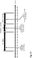
- peak hourly grid load demand and/or peak power consumption may generally occur, between about 4:00 PM (16:00) and about 8:00 PM (20:00).
- peak photovoltaic (PV) power generation may generally occur, for example, between about 11:00 AM (11:00) and about 3:00 PM (15:00).
- hourly grid load demand may not match well with purely photovoltaic power generation or photovoltaic power generation without electrical energy storage.
- photovoltaic power generation is combined with electrical energy storage, such as where a power system includes both photovoltaic cells and electrical energy storage devices, a better match to the grid load demand may be realized.
- photovoltaic energy generated before the hours of peak grid load demand can be stored in a suitable electrical energy storage device and then used during the hours of peak grid load demand.
- the reconfigurable power converters and reconfigurable power systems disclosed herein may be used and/or operated in any combination of modes suitable to supply power to the grid load demand at a given time of day.
- the reconfigurable power system 76 of Figs. 7-12 may be sequentially operated in the modes illustrated in respective ones of Figs. 7-12 over the course of a normal day.
- a nonexclusive illustrative example of a method of operating a reconfigurable power system may include three sequential modes of operation: MODE 1, MODE 2, and MODE 3.
- a first power converter may be configured as a DC-DC converter that couples a DC power source, which may include at least one photovoltaic or solar cell, to an electrical energy storage device to charge the electrical energy storage device, which may include a battery.
- the reconfigurable power system may be operated in MODE 1 between, for example, about 8:00 AM (08:00) and about 3:00 PM (15:00), which may include the times of day that provide relatively high and/or peak photovoltaic power generation, but are before the hours of peak grid load demand.
- the first power converter may be configured as a DC-AC inverter that couples the DC power source to an AC power grid connection
- a second power converter is configured as a DC-DC converter and couples the electrical energy storage device to the DC power source and the first power converter, such that power is delivered to the AC power grid connection from both the DC power source and the energy stored in the electrical energy storage device.
- the reconfigurable power system may be operated in MODE 2 between, for example, about 3:00 PM (15:00) and about 6:00 PM (18:00), which may include the times of day during which peak grid load demand occurs and during which photovoltaic power generation is still available.
- the first power converter may be configured as a DC-AC inverter that couples the electrical energy storage device to the AC power grid connection to deliver stored energy to the AC power grid.
- the reconfigurable power system may be operated in MODE 3 between, for example, about 6:00 PM (18:00) and about 10:00 PM (22:00), which may include the times of day where photovoltaic power generation may not be available but the grid load demand is still high enough to warrant delivering stored energy from the energy storage device to the AC power grid.
- the first power converter may perform maximum power point tracking for at least one solar or photovoltaic cell when the first power converter is configured as a DC-DC converter that couples the DC power source to the electrical energy storage device.
- the first power converter may perform maximum power point tracking while charging a battery from a photovoltaic cell.
- methods of operating reconfigurable power systems may include configuring the first power converter as a DC-AC inverter and coupling the DC power source and/or the electrical energy storage device to the AC power grid therewith, with the second power converter coupling the electrical energy storage device to the DC power source and to the first power converter.
- the first power converter may perform maximum power point tracking for at least one solar or photovoltaic cell when the first power converter is configured as a DC-AC inverter that couples the DC power source and/or the electrical energy storage device to the AC power grid.
- the first power converter may perform maximum power point tracking while delivering power to the AC power grid from both the DC power source and the electrical energy storage device.
- methods of operating reconfigurable power systems may include configuring the first power converter as an AC-DC converter and coupling the AC power grid to the electrical energy storage device therewith.
- power may be drawn from the AC power grid to charge the electrical energy storage device, such as during hours of low grid load demand.
- a capacitor may be connected in parallel with the electrical energy storage device.
- the methods of operating reconfigurable power systems may include uncoupling the DC power source from the electrical energy storage device, equalizing a voltage of the electrical energy storage device to a voltage of the capacitor, and then configuring the first power converter as a DC-AC inverter and coupling the DC power source and the electrical energy storage device to the AC power grid after equalizing the voltage of the electrical energy storage device to the voltage of the capacitor, with the electrical energy storage device being coupled to the DC power source and the first power converter by way of the second power converter.
- Equalizing the voltage of the electrical energy storage device to the voltage of the capacitor may reduce or prevent potentially large inrush currents that may otherwise flow into the electrical energy storage device from the capacitor when the DC power source is connected to the electrical energy storage device, such as during a transition or change from MODE 1 to MODE 2. Reducing or preventing large inrush currents into the electrical energy storage device may reduce or prevent damage to the electrical energy storage device and/or improve its lifetime.
- equalizing the voltage of the electrical energy storage device to the voltage of the capacitor may include connecting the electrical energy storage device to the capacitor through a current-limiting device, such as a resistor, which may limit the current flowing into the electrical energy storage device until the voltage levels are equalized.
- a current-limiting device such as a resistor
- the reconfigurable power system 96 includes a DC power source 22 having a plurality of photovoltaic cells 78, an electrical energy storage device 24 that includes a battery, an AC power grid connection 26, a first power converter 28, a second power converter 29, a capacitor 98 connected in parallel with the electrical energy storage device 24 and the DC power source 22, a resistor 100, and a plurality of switches 62, 64, 66, 68, 69, 102 and 104.
- the power system 96 would be configured similarly to Fig. 7 , with the switches 62, 66, 69 open and the switches 64, 68, 102 closed such that the first power converter 28 couples the DC power source 22 to the electrical energy storage device 24.
- the power system 96 would be configured similarly to Fig. 10 , with the switches 62, 64 open and the switches 66, 68, 69, 102 closed such that the first power converter 28 couples the DC power source 22 and the electrical energy storage device 24 to the AC power grid connection 26, with the electrical energy storage device 24 being coupled to the DC power source 22, the first power converter 28 and the AC power grid connection 26 by way of the second power converter 29.
- the switch 102 When transitioning the reconfigurable power system 96 from MODE 1 to MODE 2, the switch 102 may be opened and the switch 104 may then be closed to selectively series-couple the electrical energy storage device 24 to the capacitor 98 through the resistor 100 to equalize the voltage, v bat , of the electrical energy storage device 24 to the voltage, v pv , of the capacitor 98 prior to opening the switch 104 and closing the switches 66, 69, 102 to couple the DC power source 22 and the electrical energy storage device 24 to the AC power grid connection 26, with the switch 64 being opened before closing the switch 66.
- the switch 102 When transitioning the reconfigurable power system 96 from the MODE 2 to the MODE 3 discussed above, the switch 102 need only be opened. However, operation of the first power converter 28 and/or its converter circuits 70 may be discontinued while opening the switch 102, which may prevent or reduce transient performance.
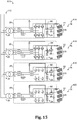
- a nonexclusive illustrative example of a power plant is shown generally at 110 in Fig. 18.
- the power plant 110 includes a plurality of reconfigurable power systems 76, which are connected together in parallel and assembled into the power plant 110, and an AC grid connection 112.
- the plurality of reconfigurable power systems 76 includes a first reconfigurable power system 114, a second reconfigurable power system 116, a third reconfigurable power system 118, and a fourth reconfigurable power system 120.
- a suitable number of suitable reconfigurable power systems 76 may be assembled into any suitably sized power plant 110.
- suitable sizes for power plant 110 may include 50 KW, 100 KW, 200 KW, 250 KW, 500 KW, or even 1000 KW or larger.
- the various reconfigurable power systems 76 within the power plant 110 may be configured into suitable combinations of modes, such as those illustrated in Figs. 7-12 , to more closely match the power delivered from the power plant 110 to the AC grid connection 112.
- the power plant 110 may be configured such that only the amount of the power requested by the AC power grid is delivered to the AC grid connection 112, with the rest of the power generated by or available from the DC power sources 22 being stored into one or more of the electrical energy storage devices 24.
- At least one of the reconfigurable power systems may be configured to deliver the power generated by its DC power source to the AC power grid
- at least one of the reconfigurable power systems may be configured to deliver a portion of the power generated by its DC power source to the AC power grid while storing the remainder of its generated power in its electrical energy storage device
- at least one of the reconfigurable power systems may be configured to store the power generated by its DC power source in its electrical energy storage device.
- Fig. 15 illustrates an example where the power plant 110 is configured to store generated power that is in excess of the grid load demand at a particular time.
- the first reconfigurable power system 114 is configured as in Fig. 9 , with its first power converter 28 configured as a DC-AC inverter that couples its DC power source 22 to its AC power grid connection 26 to deliver power from its DC power source to its AC power grid connection.
- the first power converter 28 of the first reconfigurable power system 114 may perform maximum power point tracking for the photovoltaic cells 78 of its DC power source.
- the second reconfigurable power system 116 is configured as in Fig.
- the first power converter 28 configured as a DC-AC inverter that couples its DC power source 22 to its electrical energy storage device 24 and to its AC power grid connection 26 to deliver power from its DC power source 22 to the AC power grid and to store energy in its electrical energy storage device.
- the electrical energy storage device 24 of the second reconfigurable power system 116 is coupled to the DC power source and the first power converter of the second reconfigurable power system 116 by way of the second power converter, which allows maximum power point tracking by the first power converter of the second reconfigurable power system 116.
- the third reconfigurable power system 118 and the fourth reconfigurable power system 120 are configured as in Fig.
- first power converters 28 configured as DC-DC converters that couple their DC power sources 22 to their electrical energy storage devices 24 to store energy therein.
- the first power converters of the third and fourth reconfigurable power system 118, 120 may perform maximum power point tracking for the photovoltaic cells 78 of their DC power sources.
- the following paragraphs present a nonexclusive list of examples of how the power plant 110 may be configured to supply power to and/or otherwise interact with an AC power grid.
- each of the power plant's reconfigurable power systems 76 may be configured as in Fig. 7 , with its first power converter 28 configured as a DC-DC converter that couples its DC power source 22 to its electrical energy storage device 24.
- the power plant 110 may be configured such that all power generated by the DC power sources 22 is delivered to the AC grid connection 112.
- each of the power plant's reconfigurable power systems 76 may be configured as in Fig. 9 , with the first power converter 28 configured as a DC-AC inverter that couples its DC power source 22 to its AC grid connection 26.
- the power plant 110 may be configured to deliver power to the AC grid connection 112 from at least some of the electrical energy storage devices 24 in addition to the power generated by the DC power sources 22.
- at least some of the power plant's reconfigurable power systems 76 may be configured as in Fig. 10 , with the first power converter 28 configured as a DC-AC inverter that couples its DC power source 22 and, by way of its second power converter 29, its electrical energy storage devices 24 to its AC grid connection 26.
- the power plant 110 may be configured such that the electrical energy storage devices 24 of at least some of the reconfigurable power systems 76 deliver power to the AC grid connection 112.
- the power plant's reconfigurable power systems 76 may be configured as in Fig. 11 , with the first power converter 28 configured as a DC-AC inverter that couples its electrical energy storage devices 24 to its AC power grid connection 26.
- At least some of the electrical energy storage devices 24 of the reconfigurable power systems 76 of the power plant 110 may be charged using power drawn from the AC grid connection 112.
- at least some of the power plant's reconfigurable power systems 76 may be configured as in Fig. 12 , with the first power converter 28 configured as an AC-DC converter that couples its AC power grid connection 26 to its electrical energy storage devices 24.
- the methods disclosed herein may at least partially be embodied as or take the form of the methods described herein, as well as of a transitory or non-transitory computer readable medium having a plurality of machine- or computer-readable instructions stored thereon that, when executed by a processor, carry out operations of the disclosed methods and systems.
- the computer-readable medium may be any medium that can contain, store, communicate, propagate, or transport program instruction for use by or in connection with the instruction execution system, apparatus, or device and may, by way of example but without limitation, be an electronic, magnetic, optical, electromagnetic, infrared, or semiconductor system, apparatus, device, or propagation medium or other suitable medium upon which the program is recorded.
- Such a computer-readable medium may include: a portable computer diskette, a hard disk, a random access memory (RAM), a read-only memory (ROM), an erasable programmable read-only memory (EPROM or Flash memory), an optical fiber, a portable compact disc read-only memory (CD-ROM), an optical storage device, a transmission media such as those supporting the Internet or an intranet, or a magnetic storage device.
- Computer program code or instructions for carrying out operations of the disclosed methods and systems may be written in any suitable programming language provided it allows achieving the previously described technical results. The instructions may be configured for execution on any system, apparatus or device having sufficient processing power and access to any required data.
Landscapes
- Engineering & Computer Science (AREA)
- Power Engineering (AREA)
- Supply And Distribution Of Alternating Current (AREA)
- Charge And Discharge Circuits For Batteries Or The Like (AREA)
Claims (11)
- Umkonfigurierbares Stromversorgungssystem (20), umfassend:eine Gleichstromquelle (22);eine elektrische Energiespeichervorrichtung (24);
eine Wechselstromnetzverbindung (26);einen ersten Stromwandler (28), der eine Mehrzahl von Wandlerschaltungen (70) umfasst und konfiguriert ist, um:die Gleichstromquelle (22) mit der elektrischen Energiespeichervorrichtung (24) selektiv zu koppeln,die Gleichstromquelle (22) mit der Wechselstromnetzverbindung (26) selektiv zu koppeln, unddie elektrische Energiespeichervorrichtung (24) mit der Wechselstromnetzverbindung (26) selektiv zu koppeln; undeinen zweiten Stromwandler (29), der konfiguriert ist, um die elektrische Energiespeichervorrichtung mit zumindest einem von der Gleichstromquelle und dem ersten Stromwandler selektiv zu koppeln, wobei der zweite Stromwandler als ein Gleichstrom-Gleichstrom-Wandler konfiguriert ist,dadurch gekennzeichnet, dass:der erste Stromwandler (28) in einem ersten Modus betreibbar ist, in dem ein erster Schalter (64) und ein zweiter Schalter (68) geschlossen sind, um einen ersten geschlossenen Schaltungspfad (82) zwischen der Gleichstromquelle (22) und der elektrischen Energiespeichervorrichtung (24) bereitzustellen, wobei der erste geschlossene Schaltungspfad eine Schaltvorrichtung von einer der Wandlerschaltungen (70) und einen mit der Schaltvorrichtung gekoppelten Induktor aufweist, undder erste Stromwandler in einem zweiten Modus betreibbar ist, in dem:der erste Schalter (64) offen ist, der zweite Schalter (68) und ein dritter Schalter (69) geschlossen sind, um einen zweiten geschlossenen Schaltungspfad (84) zwischen der Gleichstromquelle (22) und der elektrischen Energiespeichervorrichtung (24) bereitzustellen, wobei der zweite geschlossene Schaltungspfad die zweiten Stromwandler (29) aufweist. - Umkonfigurierbares Stromversorgungssystem (20) nach Anspruch 1, wobei die Gleichstromquelle zumindest eine photovoltaische Zelle (78) aufweist und der erste Stromwandler konfiguriert ist, um maximale Strompunktverfolgung für zumindest eine photovoltaische Zelle durchzuführen, wenn die Gleichstromquelle mit zumindest einem von der elektrischen Energiespeichervorrichtung und der Wechselstromnetzverbindung gekoppelt ist.
- Umkonfigurierbares Stromversorgungssystem (20) nach Anspruch 1, wobei die elektrische Energiespeichervorrichtung eine Batterie aufweist oder zumindest einer von dem ersten und dem zweiten Stromwandler zumindest eine Halbleiterschaltvorrichtung aufweist.
- Umkonfigurierbares Stromversorgungssystem (20) nach Anspruch 1, wobei der erste Stromwandler konfiguriert ist, um selektiv als ein Gleichstrom-Gleichstrom-Wandler, ein Gleichstrom-Wechselstrom-Inverter oder ein Wechselstrom-Gleichstrom-Wandler zu fungieren.
- Umkonfigurierbares Stromversorgungssystem (20) nach Anspruch 4, wobei:der erste Stromwandler konfiguriert ist, um als der Gleichstrom-Gleichstrom-Wandler zu fungieren, wenn die Gleichstromquelle mit der elektrischen Energiespeichervorrichtung gekoppelt ist, um die elektrische Energiespeichervorrichtung zu laden;wenn der erste Stromwandler die Gleichstromquelle und die elektrische Energiespeichervorrichtung mit der Wechselstromnetzverbindung koppelt, der erste Stromwandler konfiguriert ist, um als der Gleichstrom-Wechselstrom-Inverter zu fungieren, und der zweite Stromwandler die elektrische Energiespeichervorrichtung mit der Gleichstromquelle und dem ersten Stromwandler koppelt; undder erste Stromwandler konfiguriert ist, um als der Wechselstrom-Gleichstrom-Wandler zu fungieren, wenn die Wechselstromnetzverbindung mit der elektrischen Energiespeichervorrichtung gekoppelt ist, um die elektrische Energiespeichervorrichtung zu laden.
- Umkonfigurierbares Stromversorgungssystem (20) nach Anspruch 1, wobei:das umkonfigurierbare Stromversorgungssystem konfiguriert ist, um in einem ausgewählten von zumindest drei Modi zu arbeiten;in einem ersten der Modi, der erste Stromwandler als ein Gleichstrom-Gleichstrom-Wandler konfiguriert ist, der die Gleichstromquelle mit der elektrischen Energiespeichervorrichtung koppelt;in einem zweiten der Modi, der erste Stromwandler als ein Gleichstrom-Wechselstrom-Inverter konfiguriert ist, der die Gleichstromquelle und die elektrische Energiespeichervorrichtung mit der Wechselstromnetzverbindung koppelt, und der zweite Stromwandler die elektrische Energiespeichervorrichtung mit der Gleichstromquelle und dem ersten Stromwandler koppelt; undin einem dritten der Modi, der erste Stromwandler als ein Wechselstrom-Gleichstrom-Wandler konfiguriert ist, der die Wechselstromnetzverbindung mit der elektrischen Energiespeichervorrichtung koppelt.
- Umkonfigurierbares Stromversorgungssystem (20) nach Anspruch 1, wobei:das umkonfigurierbare Stromversorgungssystem konfiguriert ist, um in einem ausgewählten von zumindest drei Modi zu arbeiten;in einem ersten der Modi, der erste Stromwandler als ein Gleichstrom-Gleichstrom-Wandler konfiguriert ist, der die Gleichstromquelle mit der elektrischen Energiespeichervorrichtung koppelt;in einem zweiten der Modi, der erste Stromwandler als ein Gleichstrom-Wechselstrom-Inverter konfiguriert ist, der die die Gleichstromquelle und die elektrische Energiespeichervorrichtung mit der Wechselstromnetzverbindung koppelt, und wobei der zweite Stromwandler die elektrische Energiespeichervorrichtung mit der Gleichstromquelle und dem ersten Stromwandler koppelt; undin einem dritten der Modi, der erste Stromwandler als ein Gleichstrom-Wechselstrom-Inverter konfiguriert ist, der die elektrische Energiespeichervorrichtung mit der Wechselstromnetzverbindung koppelt.
- Umkonfigurierbares Stromversorgungssystem (20) nach Anspruch 7, wobei in einem vierten der zumindest drei Modi der erste Stromwandler als ein Gleichstrom-Wechselstrom-Inverter konfiguriert ist, der die Gleichstromquelle mit der Wechselstromnetzverbindung koppelt.
- Umkonfigurierbares Stromversorgungssystem (20) nach Anspruch 7, umfassend:einen Kondensator (98), der parallel zu der elektrischen Energiespeichervorrichtung (24) und der Gleichstromquelle (22) verbunden ist; undeinen Widerstand (100), der konfiguriert ist, um selektiv die elektrische Energiespeichervorrichtung mit dem Kondensator in Reihe zu koppeln.
- Kraftwerk (110), umfassend eine Mehrzahl von umkonfigurierbaren Stromversorgungssystemen (20) nach Anspruch 1, die miteinander verbunden sind.
- Kraftwerk (110) nach Anspruch 10, wobei:die Mehrzahl von umkonfigurierbaren Stromversorgungssystemen (20) ein erstes umkonfigurierbares Stromversorgungssystem (114) und ein zweites umkonfigurierbares Stromversorgungssystem (116) umfasst;in dem ersten umkonfigurierbaren Stromversorgungssystem (114) der erste Stromwandler des ersten umkonfigurierbaren Stromversorgungssystems selektiv als ein Gleichstrom-Gleichstrom-Wandler konfiguriert ist, der die Gleichstromquelle des ersten umkonfigurierbaren Stromversorgungssystems mit der elektrischen Energiespeichervorrichtung des ersten umkonfigurierbaren Stromversorgungssystems koppelt; undin dem zweiten umkonfigurierbaren Stromversorgungssystem (116) der zweite Stromwandler des zweiten umkonfigurierbaren Stromversorgungssystems selektiv als ein Gleichstrom-Wechselstrom-Inverter konfiguriert ist, der die Wechselstromnetzverbindung des zweiten umkonfigurierbaren Stromversorgungssystems mit zumindest einem von der Gleichstromquelle des zweiten umkonfigurierbaren Stromversorgungssystems und der elektrischen Energiespeichervorrichtung des zweiten umkonfigurierbaren Stromversorgungssystems koppelt, und der zweite Stromwandler des zweiten umkonfigurierbaren Stromversorgungssystems die elektrische Energiespeichervorrichtung des zweiten umkonfigurierbaren Stromversorgungssystems mit zumindest einem von der Gleichstromquelle des zweiten umkonfigurierbaren Stromversorgungssystems und dem ersten Stromwandler des zweiten umkonfigurierbaren Stromversorgungssystems koppelt.
Applications Claiming Priority (1)
| Application Number | Priority Date | Filing Date | Title |
|---|---|---|---|
| US201161476021P | 2011-04-15 | 2011-04-15 |
Publications (2)
| Publication Number | Publication Date |
|---|---|
| EP2511999A1 EP2511999A1 (de) | 2012-10-17 |
| EP2511999B1 true EP2511999B1 (de) | 2017-07-12 |
Family
ID=45930575
Family Applications (1)
| Application Number | Title | Priority Date | Filing Date |
|---|---|---|---|
| EP12159377.6A Active EP2511999B1 (de) | 2011-04-15 | 2012-03-14 | Umkonfigurierbare Leistungswandler, Systeme und Anlagen |
Country Status (3)
| Country | Link |
|---|---|
| US (1) | US20130062953A1 (de) |
| EP (1) | EP2511999B1 (de) |
| CN (1) | CN102738824B (de) |
Families Citing this family (15)
| Publication number | Priority date | Publication date | Assignee | Title |
|---|---|---|---|---|
| EP2512000B1 (de) | 2011-04-15 | 2022-03-02 | ABB Schweiz AG | Umkonfigurierbare Stromsysteme und -wandler |
| US9312699B2 (en) | 2012-10-11 | 2016-04-12 | Flexgen Power Systems, Inc. | Island grid power supply apparatus and methods using energy storage for transient stabilization |
| US10289080B2 (en) | 2012-10-11 | 2019-05-14 | Flexgen Power Systems, Inc. | Multi-generator applications using variable speed and solid state generators for efficiency and frequency stabilization |
| US9553517B2 (en) * | 2013-03-01 | 2017-01-24 | Fllexgen Power Systems, Inc. | Hybrid energy storage system and methods |
| EP2827467A3 (de) * | 2013-07-18 | 2015-04-22 | Solantro Semiconductor Corp. | Stabilisierte Stromerzeugung |
| WO2015122994A1 (en) * | 2014-02-13 | 2015-08-20 | Nextronex, Inc. | Grid tie solar inverter system with storage |
| US9923487B2 (en) * | 2014-04-14 | 2018-03-20 | Tmeic Corporation | Hybrid power converter for renewable energy power plant |
| EP3241262B1 (de) | 2014-12-30 | 2020-08-19 | Flexgen Power Systems, Inc. | Transiente leistungsstabilisierungsvorrichtung mit aktiver und reaktiver leistungsregelung |
| JP2016187292A (ja) * | 2015-03-27 | 2016-10-27 | パナソニックIpマネジメント株式会社 | 蓄電システム及び管理装置 |
| EP3398245A4 (de) * | 2015-12-31 | 2019-08-21 | EnSync, Inc. | Verfahren und vorrichtung zur verwaltung des stromflusses zwischen einer alternativen energiequelle und einer speichervorrichtung |
| WO2019113771A1 (en) * | 2017-12-12 | 2019-06-20 | Abb Schweiz Ag | Reconfigurable electric vehicle charging system |
| AU2019435207B2 (en) * | 2019-03-15 | 2024-12-19 | Ge Grid Solutions Llc | Customizable power converter and customizable power conversion system |
| ES3041288T3 (en) | 2019-10-16 | 2025-11-11 | Vestas Wind Sys As | Auxiliary power system control in hybrid power plants |
| JP7583694B2 (ja) * | 2021-09-15 | 2024-11-14 | 株式会社東芝 | バイパス回路、電力システムの制御方法、及びプログラム |
| CN117175895B (zh) * | 2023-08-30 | 2026-04-14 | 武汉森木磊石科技有限公司 | 一种多功能功率变换器平台 |
Citations (1)
| Publication number | Priority date | Publication date | Assignee | Title |
|---|---|---|---|---|
| WO2009155445A2 (en) * | 2008-06-18 | 2009-12-23 | Premium Power Corporation | Integrated renewable energy generation and storage systems and associated methods |
Family Cites Families (19)
| Publication number | Priority date | Publication date | Assignee | Title |
|---|---|---|---|---|
| US3686867A (en) * | 1971-03-08 | 1972-08-29 | Francis R Hull | Regenerative ranking cycle power plant |
| JP3571860B2 (ja) | 1996-08-23 | 2004-09-29 | キヤノン株式会社 | 非安定電源を電源とする電動機運転装置 |
| US6057665A (en) | 1998-09-18 | 2000-05-02 | Fire Wind & Rain Technologies Llc | Battery charger with maximum power tracking |
| AUPS143902A0 (en) | 2002-03-28 | 2002-05-09 | Curtin University Of Technology | Power conversion system and method of converting power |
| JP2005526363A (ja) * | 2002-05-16 | 2005-09-02 | バラード パワー システムズ インコーポレイティド | 調節可能な燃料電池システムのアレイを備える電源設備 |
| US6914418B2 (en) | 2003-04-21 | 2005-07-05 | Phoenixtec Power Co., Ltd. | Multi-mode renewable power converter system |
| US6949843B2 (en) * | 2003-07-11 | 2005-09-27 | Morningstar, Inc. | Grid-connected power systems having back-up power sources and methods of providing back-up power in grid-connected power systems |
| JP2005151662A (ja) * | 2003-11-13 | 2005-06-09 | Sharp Corp | インバータ装置および分散電源システム |
| US7684222B2 (en) * | 2004-03-24 | 2010-03-23 | Eaton Corporation | Power conversion apparatus with DC bus precharge circuits and methods of operation thereof |
| US7248946B2 (en) * | 2004-05-11 | 2007-07-24 | Advanced Energy Conversion, Llc | Inverter control methodology for distributed generation sources connected to a utility grid |
| JP4506353B2 (ja) * | 2004-08-25 | 2010-07-21 | 株式会社日立製作所 | 発電プラントにおける蒸気発生器への給水制御装置 |
| CN101765959B (zh) * | 2007-05-08 | 2015-04-15 | 美国电力转换有限公司 | 交流电源能量管理 |
| US7834580B2 (en) * | 2007-07-27 | 2010-11-16 | American Power Conversion Corporation | Solar powered apparatus |
| US8373312B2 (en) | 2008-01-31 | 2013-02-12 | General Electric Company | Solar power generation stabilization system and method |
| FI122046B (fi) * | 2009-01-12 | 2011-07-29 | Abb Oy | Aurinkovoimala |
| CN101710716A (zh) * | 2009-11-13 | 2010-05-19 | 南京航空航天大学 | 能减小电解电容的并网逆变器 |
| KR101084216B1 (ko) * | 2009-12-23 | 2011-11-17 | 삼성에스디아이 주식회사 | 에너지 저장 시스템 및 이의 제어 방법 |
| JP5627264B2 (ja) * | 2010-03-27 | 2014-11-19 | 三洋電機株式会社 | 車両用の電源装置及びこの電源装置を搭載する車両 |
| KR101410000B1 (ko) * | 2012-05-16 | 2014-07-02 | 엘지전자 주식회사 | 에너지 저장장치 및 그 동작방법 |
-
2012
- 2012-03-12 US US13/417,435 patent/US20130062953A1/en not_active Abandoned
- 2012-03-14 EP EP12159377.6A patent/EP2511999B1/de active Active
- 2012-04-13 CN CN201210112402.1A patent/CN102738824B/zh active Active
Patent Citations (1)
| Publication number | Priority date | Publication date | Assignee | Title |
|---|---|---|---|---|
| WO2009155445A2 (en) * | 2008-06-18 | 2009-12-23 | Premium Power Corporation | Integrated renewable energy generation and storage systems and associated methods |
Also Published As
| Publication number | Publication date |
|---|---|
| EP2511999A1 (de) | 2012-10-17 |
| CN102738824B (zh) | 2016-10-19 |
| US20130062953A1 (en) | 2013-03-14 |
| CN102738824A (zh) | 2012-10-17 |
Similar Documents
| Publication | Publication Date | Title |
|---|---|---|
| EP2511999B1 (de) | Umkonfigurierbare Leistungswandler, Systeme und Anlagen | |
| EP2512000B1 (de) | Umkonfigurierbare Stromsysteme und -wandler | |
| Khan et al. | A new isolated multi-port converter with multi-directional power flow capabilities for smart electric vehicle charging stations | |
| She et al. | On integration of solid-state transformer with zonal DC microgrid | |
| US9762055B2 (en) | Electric energy storage system comprising an inverter | |
| US6369461B1 (en) | High efficiency power conditioner employing low voltage DC bus and buck and boost converters | |
| JP5342598B2 (ja) | 電力変換器 | |
| CN201312133Y (zh) | 一种充电设备、储能装置及充电站 | |
| JP5290349B2 (ja) | 直流給電システムおよびその制御方法 | |
| US9257859B2 (en) | Dynamic battery control based on demand | |
| CN106877368A (zh) | 一种光伏发电微网系统混合储能控制方法 | |
| CN104779645A (zh) | 一种光伏发电系统及其控制方法 | |
| Ryu et al. | Test bed implementation of 380V DC distribution system using isolated bidirectional power converters | |
| US9748796B2 (en) | Multi-port energy storage system and control method thereof | |
| CN102969742A (zh) | 多功能光伏发电实验系统及其控制方法 | |
| Bozchalui et al. | Optimal operation of energy storage in distribution systems with renewable energy resources | |
| Bharathidasan et al. | Intelligent Fuzzy Based High Gain Non-Isolated Converter for DC Micro-Grids. | |
| Chiu et al. | Design and implementation of a high‐efficiency bidirectional DC‐DC Converter for DC micro‐grid system applications | |
| Shojaie et al. | A multi-input DC-DC converter with AC-DC PFC buck-boost stage for hybrid energy storage systems | |
| CN209896700U (zh) | 统一电能质量控制器 | |
| CN105281401A (zh) | 一种新型蓄电池化成充放电系统 | |
| Chen et al. | A family of bidirectional DC/DC converters suitable for asymmetrical power flow requirement | |
| CN204046191U (zh) | 110千伏变电站微网的交直流一体化电源系统 | |
| Yu et al. | Power management strategy for DC microgrid interfaced to distribution system based on solid state transformer | |
| JP2012222973A (ja) | 無停電電源システム |
Legal Events
| Date | Code | Title | Description |
|---|---|---|---|
| PUAI | Public reference made under article 153(3) epc to a published international application that has entered the european phase |
Free format text: ORIGINAL CODE: 0009012 |
|
| AK | Designated contracting states |
Kind code of ref document: A1 Designated state(s): AL AT BE BG CH CY CZ DE DK EE ES FI FR GB GR HR HU IE IS IT LI LT LU LV MC MK MT NL NO PL PT RO RS SE SI SK SM TR |
|
| AX | Request for extension of the european patent |
Extension state: BA ME |
|
| 17P | Request for examination filed |
Effective date: 20130405 |
|
| RIC1 | Information provided on ipc code assigned before grant |
Ipc: H02J 3/38 20060101ALI20131104BHEP Ipc: H02J 3/32 20060101AFI20131104BHEP |
|
| 17Q | First examination report despatched |
Effective date: 20140211 |
|
| REG | Reference to a national code |
Ref country code: DE Ref legal event code: R079 Ref document number: 602012034341 Country of ref document: DE Free format text: PREVIOUS MAIN CLASS: H02J0003320000 Ipc: H02J0003380000 |
|
| GRAP | Despatch of communication of intention to grant a patent |
Free format text: ORIGINAL CODE: EPIDOSNIGR1 |
|
| RIC1 | Information provided on ipc code assigned before grant |
Ipc: H02J 3/32 20060101ALI20170110BHEP Ipc: H02J 3/38 20060101AFI20170110BHEP Ipc: H02S 40/38 20140101ALI20170110BHEP |
|
| INTG | Intention to grant announced |
Effective date: 20170206 |
|
| RIN1 | Information on inventor provided before grant (corrected) |
Inventor name: NURMI , JUKKA Inventor name: KIM, HONGRAE Inventor name: ARSHAD, WAQAS |
|
| GRAS | Grant fee paid |
Free format text: ORIGINAL CODE: EPIDOSNIGR3 |
|
| GRAA | (expected) grant |
Free format text: ORIGINAL CODE: 0009210 |
|
| AK | Designated contracting states |
Kind code of ref document: B1 Designated state(s): AL AT BE BG CH CY CZ DE DK EE ES FI FR GB GR HR HU IE IS IT LI LT LU LV MC MK MT NL NO PL PT RO RS SE SI SK SM TR |
|
| REG | Reference to a national code |
Ref country code: GB Ref legal event code: FG4D |
|
| REG | Reference to a national code |
Ref country code: CH Ref legal event code: EP |
|
| REG | Reference to a national code |
Ref country code: AT Ref legal event code: REF Ref document number: 909172 Country of ref document: AT Kind code of ref document: T Effective date: 20170715 |
|
| REG | Reference to a national code |
Ref country code: IE Ref legal event code: FG4D |
|
| REG | Reference to a national code |
Ref country code: DE Ref legal event code: R096 Ref document number: 602012034341 Country of ref document: DE |
|
| REG | Reference to a national code |
Ref country code: NL Ref legal event code: MP Effective date: 20170712 |
|
| REG | Reference to a national code |
Ref country code: LT Ref legal event code: MG4D |
|
| REG | Reference to a national code |
Ref country code: AT Ref legal event code: MK05 Ref document number: 909172 Country of ref document: AT Kind code of ref document: T Effective date: 20170712 |
|
| PG25 | Lapsed in a contracting state [announced via postgrant information from national office to epo] |
Ref country code: LT Free format text: LAPSE BECAUSE OF FAILURE TO SUBMIT A TRANSLATION OF THE DESCRIPTION OR TO PAY THE FEE WITHIN THE PRESCRIBED TIME-LIMIT Effective date: 20170712 Ref country code: AT Free format text: LAPSE BECAUSE OF FAILURE TO SUBMIT A TRANSLATION OF THE DESCRIPTION OR TO PAY THE FEE WITHIN THE PRESCRIBED TIME-LIMIT Effective date: 20170712 Ref country code: NL Free format text: LAPSE BECAUSE OF FAILURE TO SUBMIT A TRANSLATION OF THE DESCRIPTION OR TO PAY THE FEE WITHIN THE PRESCRIBED TIME-LIMIT Effective date: 20170712 Ref country code: FI Free format text: LAPSE BECAUSE OF FAILURE TO SUBMIT A TRANSLATION OF THE DESCRIPTION OR TO PAY THE FEE WITHIN THE PRESCRIBED TIME-LIMIT Effective date: 20170712 Ref country code: NO Free format text: LAPSE BECAUSE OF FAILURE TO SUBMIT A TRANSLATION OF THE DESCRIPTION OR TO PAY THE FEE WITHIN THE PRESCRIBED TIME-LIMIT Effective date: 20171012 Ref country code: SE Free format text: LAPSE BECAUSE OF FAILURE TO SUBMIT A TRANSLATION OF THE DESCRIPTION OR TO PAY THE FEE WITHIN THE PRESCRIBED TIME-LIMIT Effective date: 20170712 Ref country code: HR Free format text: LAPSE BECAUSE OF FAILURE TO SUBMIT A TRANSLATION OF THE DESCRIPTION OR TO PAY THE FEE WITHIN THE PRESCRIBED TIME-LIMIT Effective date: 20170712 |
|
| PG25 | Lapsed in a contracting state [announced via postgrant information from national office to epo] |
Ref country code: ES Free format text: LAPSE BECAUSE OF FAILURE TO SUBMIT A TRANSLATION OF THE DESCRIPTION OR TO PAY THE FEE WITHIN THE PRESCRIBED TIME-LIMIT Effective date: 20170712 Ref country code: BG Free format text: LAPSE BECAUSE OF FAILURE TO SUBMIT A TRANSLATION OF THE DESCRIPTION OR TO PAY THE FEE WITHIN THE PRESCRIBED TIME-LIMIT Effective date: 20171012 Ref country code: RS Free format text: LAPSE BECAUSE OF FAILURE TO SUBMIT A TRANSLATION OF THE DESCRIPTION OR TO PAY THE FEE WITHIN THE PRESCRIBED TIME-LIMIT Effective date: 20170712 Ref country code: IS Free format text: LAPSE BECAUSE OF FAILURE TO SUBMIT A TRANSLATION OF THE DESCRIPTION OR TO PAY THE FEE WITHIN THE PRESCRIBED TIME-LIMIT Effective date: 20171112 Ref country code: PL Free format text: LAPSE BECAUSE OF FAILURE TO SUBMIT A TRANSLATION OF THE DESCRIPTION OR TO PAY THE FEE WITHIN THE PRESCRIBED TIME-LIMIT Effective date: 20170712 Ref country code: LV Free format text: LAPSE BECAUSE OF FAILURE TO SUBMIT A TRANSLATION OF THE DESCRIPTION OR TO PAY THE FEE WITHIN THE PRESCRIBED TIME-LIMIT Effective date: 20170712 Ref country code: GR Free format text: LAPSE BECAUSE OF FAILURE TO SUBMIT A TRANSLATION OF THE DESCRIPTION OR TO PAY THE FEE WITHIN THE PRESCRIBED TIME-LIMIT Effective date: 20171013 |
|
| REG | Reference to a national code |
Ref country code: FR Ref legal event code: PLFP Year of fee payment: 7 |
|
| REG | Reference to a national code |
Ref country code: DE Ref legal event code: R097 Ref document number: 602012034341 Country of ref document: DE |
|
| PG25 | Lapsed in a contracting state [announced via postgrant information from national office to epo] |
Ref country code: CZ Free format text: LAPSE BECAUSE OF FAILURE TO SUBMIT A TRANSLATION OF THE DESCRIPTION OR TO PAY THE FEE WITHIN THE PRESCRIBED TIME-LIMIT Effective date: 20170712 Ref country code: DK Free format text: LAPSE BECAUSE OF FAILURE TO SUBMIT A TRANSLATION OF THE DESCRIPTION OR TO PAY THE FEE WITHIN THE PRESCRIBED TIME-LIMIT Effective date: 20170712 Ref country code: RO Free format text: LAPSE BECAUSE OF FAILURE TO SUBMIT A TRANSLATION OF THE DESCRIPTION OR TO PAY THE FEE WITHIN THE PRESCRIBED TIME-LIMIT Effective date: 20170712 |
|
| PLBE | No opposition filed within time limit |
Free format text: ORIGINAL CODE: 0009261 |
|
| STAA | Information on the status of an ep patent application or granted ep patent |
Free format text: STATUS: NO OPPOSITION FILED WITHIN TIME LIMIT |
|
| PG25 | Lapsed in a contracting state [announced via postgrant information from national office to epo] |
Ref country code: EE Free format text: LAPSE BECAUSE OF FAILURE TO SUBMIT A TRANSLATION OF THE DESCRIPTION OR TO PAY THE FEE WITHIN THE PRESCRIBED TIME-LIMIT Effective date: 20170712 Ref country code: SK Free format text: LAPSE BECAUSE OF FAILURE TO SUBMIT A TRANSLATION OF THE DESCRIPTION OR TO PAY THE FEE WITHIN THE PRESCRIBED TIME-LIMIT Effective date: 20170712 Ref country code: SM Free format text: LAPSE BECAUSE OF FAILURE TO SUBMIT A TRANSLATION OF THE DESCRIPTION OR TO PAY THE FEE WITHIN THE PRESCRIBED TIME-LIMIT Effective date: 20170712 |
|
| 26N | No opposition filed |
Effective date: 20180413 |
|
| PG25 | Lapsed in a contracting state [announced via postgrant information from national office to epo] |
Ref country code: SI Free format text: LAPSE BECAUSE OF FAILURE TO SUBMIT A TRANSLATION OF THE DESCRIPTION OR TO PAY THE FEE WITHIN THE PRESCRIBED TIME-LIMIT Effective date: 20170712 |
|
| REG | Reference to a national code |
Ref country code: CH Ref legal event code: PL |
|
| PG25 | Lapsed in a contracting state [announced via postgrant information from national office to epo] |
Ref country code: MC Free format text: LAPSE BECAUSE OF FAILURE TO SUBMIT A TRANSLATION OF THE DESCRIPTION OR TO PAY THE FEE WITHIN THE PRESCRIBED TIME-LIMIT Effective date: 20170712 |
|
| REG | Reference to a national code |
Ref country code: BE Ref legal event code: MM Effective date: 20180331 |
|
| REG | Reference to a national code |
Ref country code: IE Ref legal event code: MM4A |
|
| PG25 | Lapsed in a contracting state [announced via postgrant information from national office to epo] |
Ref country code: LU Free format text: LAPSE BECAUSE OF NON-PAYMENT OF DUE FEES Effective date: 20180314 |
|
| PG25 | Lapsed in a contracting state [announced via postgrant information from national office to epo] |
Ref country code: IE Free format text: LAPSE BECAUSE OF NON-PAYMENT OF DUE FEES Effective date: 20180314 |
|
| PG25 | Lapsed in a contracting state [announced via postgrant information from national office to epo] |
Ref country code: BE Free format text: LAPSE BECAUSE OF NON-PAYMENT OF DUE FEES Effective date: 20180331 Ref country code: LI Free format text: LAPSE BECAUSE OF NON-PAYMENT OF DUE FEES Effective date: 20180331 Ref country code: CH Free format text: LAPSE BECAUSE OF NON-PAYMENT OF DUE FEES Effective date: 20180331 |
|
| REG | Reference to a national code |
Ref country code: DE Ref legal event code: R082 Ref document number: 602012034341 Country of ref document: DE Representative=s name: STOLMAR & PARTNER PATENTANWAELTE PARTG MBB, DE Ref country code: DE Ref legal event code: R081 Ref document number: 602012034341 Country of ref document: DE Owner name: ABB SCHWEIZ AG, CH Free format text: FORMER OWNER: ABB RESEARCH LTD., ZUERICH, CH |
|
| PG25 | Lapsed in a contracting state [announced via postgrant information from national office to epo] |
Ref country code: MT Free format text: LAPSE BECAUSE OF NON-PAYMENT OF DUE FEES Effective date: 20180314 |
|
| REG | Reference to a national code |
Ref country code: GB Ref legal event code: 732E Free format text: REGISTERED BETWEEN 20200206 AND 20200212 |
|
| PG25 | Lapsed in a contracting state [announced via postgrant information from national office to epo] |
Ref country code: TR Free format text: LAPSE BECAUSE OF FAILURE TO SUBMIT A TRANSLATION OF THE DESCRIPTION OR TO PAY THE FEE WITHIN THE PRESCRIBED TIME-LIMIT Effective date: 20170712 |
|
| PG25 | Lapsed in a contracting state [announced via postgrant information from national office to epo] |
Ref country code: HU Free format text: LAPSE BECAUSE OF FAILURE TO SUBMIT A TRANSLATION OF THE DESCRIPTION OR TO PAY THE FEE WITHIN THE PRESCRIBED TIME-LIMIT; INVALID AB INITIO Effective date: 20120314 Ref country code: PT Free format text: LAPSE BECAUSE OF FAILURE TO SUBMIT A TRANSLATION OF THE DESCRIPTION OR TO PAY THE FEE WITHIN THE PRESCRIBED TIME-LIMIT Effective date: 20170712 |
|
| PG25 | Lapsed in a contracting state [announced via postgrant information from national office to epo] |
Ref country code: CY Free format text: LAPSE BECAUSE OF FAILURE TO SUBMIT A TRANSLATION OF THE DESCRIPTION OR TO PAY THE FEE WITHIN THE PRESCRIBED TIME-LIMIT Effective date: 20170712 Ref country code: MK Free format text: LAPSE BECAUSE OF NON-PAYMENT OF DUE FEES Effective date: 20170712 |
|
| PG25 | Lapsed in a contracting state [announced via postgrant information from national office to epo] |
Ref country code: AL Free format text: LAPSE BECAUSE OF FAILURE TO SUBMIT A TRANSLATION OF THE DESCRIPTION OR TO PAY THE FEE WITHIN THE PRESCRIBED TIME-LIMIT Effective date: 20170712 |
|
| PGFP | Annual fee paid to national office [announced via postgrant information from national office to epo] |
Ref country code: GB Payment date: 20260324 Year of fee payment: 15 |
|
| PGFP | Annual fee paid to national office [announced via postgrant information from national office to epo] |
Ref country code: DE Payment date: 20260319 Year of fee payment: 15 |
|
| PGFP | Annual fee paid to national office [announced via postgrant information from national office to epo] |
Ref country code: IT Payment date: 20260324 Year of fee payment: 15 |
|
| PGFP | Annual fee paid to national office [announced via postgrant information from national office to epo] |
Ref country code: FR Payment date: 20260320 Year of fee payment: 15 |