EP2511886B1 - Automatic teller machine - Google Patents
Automatic teller machine Download PDFInfo
- Publication number
- EP2511886B1 EP2511886B1 EP10841329.5A EP10841329A EP2511886B1 EP 2511886 B1 EP2511886 B1 EP 2511886B1 EP 10841329 A EP10841329 A EP 10841329A EP 2511886 B1 EP2511886 B1 EP 2511886B1
- Authority
- EP
- European Patent Office
- Prior art keywords
- carriage
- medium
- disposed
- paper
- rotor
- Prior art date
- Legal status (The legal status is an assumption and is not a legal conclusion. Google has not performed a legal analysis and makes no representation as to the accuracy of the status listed.)
- Active
Links
- 238000007689 inspection Methods 0.000 claims description 34
- 230000002159 abnormal effect Effects 0.000 claims description 31
- 238000009434 installation Methods 0.000 description 5
- 238000000034 method Methods 0.000 description 4
- 238000001514 detection method Methods 0.000 description 3
- 238000013459 approach Methods 0.000 description 2
- 239000013013 elastic material Substances 0.000 description 2
- 230000000694 effects Effects 0.000 description 1
- 230000003287 optical effect Effects 0.000 description 1
Images


Classifications
-
- B—PERFORMING OPERATIONS; TRANSPORTING
- B65—CONVEYING; PACKING; STORING; HANDLING THIN OR FILAMENTARY MATERIAL
- B65H—HANDLING THIN OR FILAMENTARY MATERIAL, e.g. SHEETS, WEBS, CABLES
- B65H29/00—Delivering or advancing articles from machines; Advancing articles to or into piles
- B65H29/58—Article switches or diverters
-
- B—PERFORMING OPERATIONS; TRANSPORTING
- B65—CONVEYING; PACKING; STORING; HANDLING THIN OR FILAMENTARY MATERIAL
- B65H—HANDLING THIN OR FILAMENTARY MATERIAL, e.g. SHEETS, WEBS, CABLES
- B65H31/00—Pile receivers
- B65H31/24—Pile receivers multiple or compartmented, e.d. for alternate, programmed, or selective filling
-
- B—PERFORMING OPERATIONS; TRANSPORTING
- B65—CONVEYING; PACKING; STORING; HANDLING THIN OR FILAMENTARY MATERIAL
- B65H—HANDLING THIN OR FILAMENTARY MATERIAL, e.g. SHEETS, WEBS, CABLES
- B65H31/00—Pile receivers
- B65H31/30—Arrangements for removing completed piles
- B65H31/3027—Arrangements for removing completed piles by the nip between moving belts or rollers
-
- B—PERFORMING OPERATIONS; TRANSPORTING
- B65—CONVEYING; PACKING; STORING; HANDLING THIN OR FILAMENTARY MATERIAL
- B65H—HANDLING THIN OR FILAMENTARY MATERIAL, e.g. SHEETS, WEBS, CABLES
- B65H31/00—Pile receivers
- B65H31/30—Arrangements for removing completed piles
- B65H31/3036—Arrangements for removing completed piles by gripping the pile
- B65H31/3045—Arrangements for removing completed piles by gripping the pile on the outermost articles of the pile for clamping the pile
-
- G—PHYSICS
- G07—CHECKING-DEVICES
- G07D—HANDLING OF COINS OR VALUABLE PAPERS, e.g. TESTING, SORTING BY DENOMINATIONS, COUNTING, DISPENSING, CHANGING OR DEPOSITING
- G07D11/00—Devices accepting coins; Devices accepting, dispensing, sorting or counting valuable papers
- G07D11/10—Mechanical details
-
- G—PHYSICS
- G07—CHECKING-DEVICES
- G07F—COIN-FREED OR LIKE APPARATUS
- G07F19/00—Complete banking systems; Coded card-freed arrangements adapted for dispensing or receiving monies or the like and posting such transactions to existing accounts, e.g. automatic teller machines
- G07F19/20—Automatic teller machines [ATMs]
-
- B—PERFORMING OPERATIONS; TRANSPORTING
- B65—CONVEYING; PACKING; STORING; HANDLING THIN OR FILAMENTARY MATERIAL
- B65H—HANDLING THIN OR FILAMENTARY MATERIAL, e.g. SHEETS, WEBS, CABLES
- B65H2301/00—Handling processes for sheets or webs
- B65H2301/40—Type of handling process
- B65H2301/42—Piling, depiling, handling piles
- B65H2301/421—Forming a pile
- B65H2301/4213—Forming a pile of a limited number of articles, e.g. buffering, forming bundles
-
- B—PERFORMING OPERATIONS; TRANSPORTING
- B65—CONVEYING; PACKING; STORING; HANDLING THIN OR FILAMENTARY MATERIAL
- B65H—HANDLING THIN OR FILAMENTARY MATERIAL, e.g. SHEETS, WEBS, CABLES
- B65H2301/00—Handling processes for sheets or webs
- B65H2301/40—Type of handling process
- B65H2301/44—Moving, forwarding, guiding material
- B65H2301/447—Moving, forwarding, guiding material transferring material between transport devices
- B65H2301/4474—Pair of cooperating moving elements as rollers, belts forming nip into which material is transported
-
- B—PERFORMING OPERATIONS; TRANSPORTING
- B65—CONVEYING; PACKING; STORING; HANDLING THIN OR FILAMENTARY MATERIAL
- B65H—HANDLING THIN OR FILAMENTARY MATERIAL, e.g. SHEETS, WEBS, CABLES
- B65H2402/00—Constructional details of the handling apparatus
- B65H2402/30—Supports; Subassemblies; Mountings thereof
- B65H2402/31—Pivoting support means
-
- B—PERFORMING OPERATIONS; TRANSPORTING
- B65—CONVEYING; PACKING; STORING; HANDLING THIN OR FILAMENTARY MATERIAL
- B65H—HANDLING THIN OR FILAMENTARY MATERIAL, e.g. SHEETS, WEBS, CABLES
- B65H2404/00—Parts for transporting or guiding the handled material
- B65H2404/20—Belts
- B65H2404/26—Particular arrangement of belt, or belts
- B65H2404/269—Particular arrangement of belt, or belts other arrangements
- B65H2404/2693—Arrangement of belts on movable frame
-
- B—PERFORMING OPERATIONS; TRANSPORTING
- B65—CONVEYING; PACKING; STORING; HANDLING THIN OR FILAMENTARY MATERIAL
- B65H—HANDLING THIN OR FILAMENTARY MATERIAL, e.g. SHEETS, WEBS, CABLES
- B65H2404/00—Parts for transporting or guiding the handled material
- B65H2404/60—Other elements in face contact with handled material
- B65H2404/69—Other means designated for special purpose
- B65H2404/693—Retractable guiding means, i.e. between guiding and non guiding position
-
- B—PERFORMING OPERATIONS; TRANSPORTING
- B65—CONVEYING; PACKING; STORING; HANDLING THIN OR FILAMENTARY MATERIAL
- B65H—HANDLING THIN OR FILAMENTARY MATERIAL, e.g. SHEETS, WEBS, CABLES
- B65H2405/00—Parts for holding the handled material
- B65H2405/30—Other features of supports for sheets
- B65H2405/35—Means for moving support
-
- B—PERFORMING OPERATIONS; TRANSPORTING
- B65—CONVEYING; PACKING; STORING; HANDLING THIN OR FILAMENTARY MATERIAL
- B65H—HANDLING THIN OR FILAMENTARY MATERIAL, e.g. SHEETS, WEBS, CABLES
- B65H2701/00—Handled material; Storage means
- B65H2701/10—Handled articles or webs
- B65H2701/19—Specific article or web
- B65H2701/1912—Banknotes, bills and cheques or the like
Definitions
- the present invention relates to an automatic teller machine (ATM), and more particularly, to an ATM capable of reducing a jam of paper mediums, simplifying an inner structure and a money withdrawal operation, and collecting a rejected paper medium and a retracted paper medium during transfer along a medium transfer unit in one space.
- ATM automatic teller machine
- an automatic teller machine refers to an automated apparatus providing fundamental monetary services, such as payment and withdrawal of cash and check, using a card or a bankbook regardless of time and places without a bank teller.
- ATM automatic teller machine
- use of the ATM is not limited to banking facilities such as banks but expanded to convenience stores, department stores, and other public places.
- the ATM may be classified into a cash dispenser, a cash receiver, and a cash dispenser and receiver. In these days, the ATM is used for not only payment and withdrawal of cash but also payment and withdrawal of check, bankbook arrangement, fee payment by giro, ticketing, and the like.
- a rejected paper medium is stored in a rejected medium storage unit and, separately, a paper medium not received by a dispenser portion but retracted is stored in a retracted medium storage unit.
- Another aspect of the present invention provides an ATM structured such that a storage portion to store the rejected paper medium and a storage portion to store the retracted paper medium are integrated, thereby reducing the entire size and also reducing cost.
- an automatic teller machine including a case in which a plurality of dispenser portions are disposed in different positions, a medium storage unit provided to the case to store paper mediums, a medium transfer unit to transfer the paper mediums sheet by sheet from the medium storage unit, a medium inspection unit provided to the medium transfer unit to detect the paper mediums being transferred by the medium transfer unit, a carriage in which paper mediums determined to be normal by the medium inspection unit are stacked, the carriage configured to be transferred along any one of movement paths connected to the plurality of dispenser portions to dispense the paper mediums through any one of the plurality of dispenser portions, a rotor in which the carriage is withdrawably inserted, the rotor rotatably mounted in the case and rotated along with the carriage in any position between a first position in which the paper mediums are stacked in the carriage and a second position in which the carriage is moved to the movement paths, and a medium collection unit disposed in the case such that paper mediums determined to be abnormal by the medium inspection
- the paper mediums determined to be abnormal may be collected in real time by the medium collection unit. Therefore, a dedicated operation mode for collecting the paper medium determined to be abnormal by the medium inspection unit is unnecessary. Also, an operation for stacking the paper mediums in the carriage may be continuously performed without interference with the abnormal paper mediums.
- a plurality of the medium storage units may be provided at the case.
- the medium transfer unit may selectively transfer the paper medium stored in any one of the medium storage units.
- the plurality of dispenser portions may include a front dispenser portion disposed on a front portion of the case, a rear dispenser disposed at a rear portion of the case, and an upper dispenser disposed at an upper surface of the case.
- the movement paths may include a front movement path disposed between the front dispenser and the rotor, a rear movement path disposed between the rear dispenser and the rotor, and an upper movement path disposed between the upper dispenser and the rotor.
- the number of the dispenser portions and the movement paths may be varied according to the design and conditions of the ATM.
- the movement paths each include guide rails disposed on opposite lateral sides of the case to guide a movement direction of the carriage, and rail gears arranged in a length direction of the guide rails
- the carriage may include guide rollers disposed on opposite lateral sides to be moved along the guide rails, respectively, and moving gears disposed on the opposite lateral sides of the carriage to be engaged with and moved along the rail gears, respectively. Accordingly, the carriage may be stably supported by the guide roller and the moving gear, and moved along the rail gears by the moving gear.
- the carriage may include a first carriage portion provided with the guide rollers and the moving gears disposed on the opposite lateral sides, and rotated along with the rotor when the rotor rotates, a second carriage portion disposed to face the first carriage portion such that the paper mediums are disposed between the first carriage portion and the second carriage portion, and a carriage driving portion to which the first carriage portion and the second carriage portion are foldably connected, the carriage driving portion configured to drive the moving gear.
- the first carriage portion may include a first transfer belt brought into tight contact with one surface of the paper mediums
- the second carriage portion may include a second transfer belt brought into tight contact with the other surface of the paper mediums
- the first transfer belt and the second transfer belt may be driven by the carriage driving portion. Therefore, when the first transfer belt and the second transfer belt are driven in a folded state by the carriage driving portion, the paper mediums disposed between the first carriage portion and the second carriage portion may be withdrawn out of the carriage.
- the carriage driving portion may include a first carriage driving portion connected to the moving gear to drive the moving gear, and a second carriage driving portion connected to the first transfer belt and the second transfer belt to drive the first transfer belt and the second transfer belt.
- the second carriage portion may include an opening projection configured to be interfered with the case or the medium transfer unit such that the first carriage portion and the second carriage portion are separated from each other when the rotor rotates to the first position, thereby restricting rotation of the second carriage portion.
- the rotor may include rotation portions rotatably disposed on opposite lateral sides of the case so as to support movement of opposite lateral sides of the carriage, and a connecting portion of which opposite sides are connected to the rotation portions and in which the carriage is mounted.
- the medium collection unit may include a reject box to receive the paper mediums determined to be abnormal by the medium inspection unit, and a reject transfer portion including a path bypassing the rotor and the carriage between the reject box and the medium transfer unit and transferring the paper mediums to the reject box. Accordingly, the paper mediums determined to be abnormal by the medium inspection unit may be not stacked in the carriage but collected in the reject box along the reject transfer portion. The operation of the medium transfer unit may not be stopped during this, and stacking of the paper mediums in the carriage may be continued.
- the ATM may further include a retract box to store paper mediums collected from the dispenser portions when the paper mediums dispensed to the dispenser portions are not received.
- An entrance of the retract box may be directed to the rotor. Therefore, when the rotor rotates the carriage toward the entrance of the retract box, the carriage may be moved to the entrance of the retract box and insert the paper mediums into the retract box.
- the ATM may further include a main driving portion disposed in the case to supply a driving force to the medium transfer unit and the medium collection unit.
- a paper medium detected to be abnormal during transfer along the medium transfer portion and determined to be rejected, and a paper medium not received by the dispenser portions but retracted may be collected in one space, thereby simplifying the overall structure.
- the direction guide portion may include a guide body and a rotational axis for axially rotating the guide body, and the guide body may be direction-converted by a pressing force of the paper mediums approaching the guide body.
- the carrier position adjustment portion may include a carrier guide disposed between an entrance of the collected medium storage portion and the carrier position adjustment portion so that the medium carrier approaches the entrance when the paper mediums are retracted.
- a rotation roller unit may be mounted at an entrance area of the collected medium storage portion to introduce the paper mediums to an inner space of the collected medium storage portion.
- the rotation roller unit may include an upper roller portion including a rotational axis axially rotated by a driving source and a plurality of rollers arranged in a length direction of the rotational axis, and a lower roller portion including a rotational axis rotated in an opposite direction to rotation of the rotational axis of the upper roller portion and a plurality of rollers arranged in a length direction of the rotational axis of the lower roller portion, and wherein the pluralities of rollers may be made of an elastic material elastically deformable in an inward direction. Accordingly, the plurality of paper mediums may be passed through the rotation roller unit and introduced into the collected medium storage portion.
- the entrance area of the collected medium storage portion may include a rotation guide freely rotated according to an advancing direction of the paper mediums to guide the paper mediums discharged from the rejected medium transfer portion or the medium carrier into the rotation roller unit. Therefore, the rejected or retracted paper medium may be stably transferred to the collected medium storage portion without escaping.
- a structure for transferring paper mediums may be simplified since the paper mediums are transferred in a bundle directly by a carriage to a dispenser portion.
- a jam of paper mediums generated during transfer of the paper mediums may be reduced, thereby preventing reduction in efficiency of the ATM.
- the ATM is structured in such a manner that a carriage in which paper mediums are stacked is directly transferred to a plurality of dispenser portions along movement paths of a case. Therefore, control of a dispensing operation of the ATM may be simplified, and a dispensing time for the paper mediums may be reduced. That is, the dispensing operation for the paper mediums may be quickly performed.
- the paper mediums may be dispensed to several positions of the ATM.
- the ATM may be applied in various environments.
- an advancing direction of a carriage is conveniently adjusted by a rotor. Therefore, the carriage may be conveniently disposed at any one of a medium transfer unit, dispenser portions, and a retract box.
- the movement paths of the carriage are conveniently selected and converted by rotation of the rotor, operation of the ATM may be simplified, consequently facilitating control of the ATM.
- paper mediums are transferred to the carriage or a medium collection unit according to a detection value of a medium inspection unit. That is, normal paper mediums may be transferred to the carriage while abnormal paper mediums are transferred to the medium collection unit.
- paper mediums determined to be abnormal by the medium inspection unit may be collected to the medium collection unit before being stacked in the carriage.
- a dedicated operation mode for collecting abnormal paper mediums is unnecessary.
- the operational efficiency of the ATM may be maximized.
- the ATM collects a paper medium detected to be abnormal during transfer and determined to be rejected and a paper medium not received by the dispenser portion but retracted, in one space. Accordingly, the overall structure of the ATM may be simplified.
- a storage unit to store the rejected paper medium and a storage unit to store the retracted paper medium are integrated, thereby reducing the entire size and also reducing cost.
- the ATM 100 includes a case 110, a medium storage unit 120, a medium transfer unit 130, a medium inspection unit 140, a carriage 150, a rotor 160, and a medium collection unit 170.
- the ATM 100 will be limitedly described as a cash dispenser. However, technical aspects of the present invention are applicable to a cash receiver and a combined cash receiver and dispenser.
- the medium storage unit 120 may be disposed at a lower part of the case 110.
- the medium transfer unit 130, the medium inspection unit 140, the carriage 150, the rotor 160, the medium collection unit 170, dispenser portions 111, 112, and 113, and movement paths 114, 115, and 116 may be disposed at an upper part of the case 110.
- the dispenser portions 111, 112, and 113 may be disposed in respectively different positions at the upper part of the case 110. That is, the dispenser portions 111, 112, and 113 may include a front dispenser 111 disposed at a front part of the case 110, a rear dispenser 112 disposed at a rear part of the case 110, and an upper dispenser 113 disposed at an upper surface of the case 110.
- the movement paths 114, 115, and 116 may respectively include guide rails 114a, 115a, and 116a disposed on opposite lateral sides of the case 110 to guide a movement direction of the carriage 150, and rail gears 114b, 115b, and 116b arranged in a length direction of the guide rails 114a, 115a, and 116a, respectively.
- a guide roller 157 of the carriage 150 may be movably inserted in the guide rails 114a, 115a, and 116a, which will be described later.
- the rail gears 114b, 115b, and 116b may be in the form of rack gears formed along the guide rails 114a, 115a, and 116a, and may be connected to a moving gear 158 of the carriage 150.
- the moving gear 158 will be described later.
- the medium storage unit 120 is adapted to store paper mediums P.
- the paper mediums P may include banknotes, checks, merchandise coupons, tickets, and the like.
- the paper mediums P will be described as banknotes for convenience of explanation.
- the medium storage unit 120 may be integrally formed with a lower part of the case 110. However, in the present embodiment, the medium storage unit 120 will be described to be removably mounted at the lower part of the case 110.
- the medium storage unit 120 may be provided in the form of a removable box such as a cassette.
- the paper mediums P may be stored in the medium storage unit 120.
- the medium transfer unit 130 is adapted to selectively transfer the paper mediums P stored in any one of the plurality of medium storage units 120 sheet by sheet.
- the medium transfer unit 130 may be disposed between the medium storage unit 120 and the rotor 160.
- the medium transfer unit 130 may supply the paper mediums P into the carriage 150 disposed at the rotor 160.
- the medium transfer unit 130 may include a plurality of rollers and belts.
- the medium inspection unit 140 detects a change in thickness of the paper mediums P being transferred by the medium transfer unit 130, thereby determining whether a single sheet of the paper mediums P is transferred.
- the medium inspection unit 140 may include two contact portions disposed in different positions, through which the paper mediums P are passed. A number of sheet of the paper mediums P may be detected by varying positions of the contact portions.
- the medium inspection unit 140 may include a plurality of contact portions disposed in respectively different positions to determine skew of the paper mediums P being transferred by the medium transfer unit 130.
- the carriage 150 may include a first carriage portion 152, a second carriage portion 154, and a carriage driving portion 156.
- the first carriage portion 152 may be provided in the form of a panel to tightly contact one surface of the paper medium P.
- the first carriage portion 152 may be rotated along with the rotor 160 as the rotor 160 is rotated.
- the paper mediums P may be stacked on one surface of the first carriage portion 152.
- the first carriage portion 152 may include a first transfer belt 152a and a first transfer pulley 152b disposed at one side of the first carriage portion 152.
- a guide roller 157 and a moving gear 158 may be disposed at opposite lateral sides of the first carriage portion 152, respectively.
- the guide roller 157 may be a roller member disposed in and moved along the guide rails 114a, 115a, and 116a.
- the moving gear 158 may be engaged with the rail gears 114b, 115b, and 116b and move along with the rail gears 114b, 115b, and 116b when rotated.
- the moving gear 158 may be a pinion gear rotated in engagement with the rail gears 114b, 115b, and 116b implemented by rack gears.
- the carriage 150 may be stably supported by the guide roller 157 and the moving gear 158.
- the carriage 150 may be moved along the rail gears 114b, 115b, and 116b by the moving gear 158.
- the second carriage portion 154 may include a second transfer belt 154a and a second transfer pulley 154b disposed at one side of the second carriage portion 154 to move the paper mediums P stacked on the one surface of the first carriage portion 152 in a bundle.
- the second transfer belt 154a and the first transfer belt 152a may be disposed to face each other.
- An opening projection 159 may be formed at one side of the second carriage portion 154.
- the opening projection 135 is a member to restrict rotation of the second carriage portion 154 by being interfered with the case 110 or the medium transfer unit 130 when the rotor 160 rotates. That is, when the rotor 160 rotates along with the carriage 150 in a direction toward the medium transfer unit 130, the opening projection 135 may be interfered with the case 110 or the medium transfer unit 130, thereby restricting rotation of the second carriage portion 154. Therefore, even while the second carriage portion 154 is stopped by the opening projection 135, since the first carriage portion 152 may continue rotating along with the rotor 160, a gap between the first carriage portion 152 and the second carriage portion 154 may be widened by a rotational force of the rotor 160.
- the carriage driving portion 156 may be connected with the first carriage portion 152 and the second carriage portion 154 to foldably support the first carriage portion 152 and the second carriage portion 154. That is, when the gap between the first carriage portion 152 and the second carriage portion 154 is widened, the paper mediums P transferred by the medium transfer unit 130 may be stacked on the one surface of the first carriage portion 152. Conversely, when the first carriage portion 152 and the second carriage portion 154 are folded to each other, the paper mediums P may be stably fixed in a bundle form between the one surface of the first carriage portion 152 and the one surface of the second carriage portion 154.
- the carriage driving portion 156 may supply a driving force to the moving gear 158, the first transfer belt 152a, and the second transfer belt 154a. That is, the carriage driving portion 156 may include a first carriage driving portion (not shown) to drive the moving gear 158 in connection with the moving gear 158, and a second carriage driving portion (not shown) to drive the first transfer belt 152a and the second transfer belt 154a in connection with the first transfer pulley 152b and the second transfer pulley 154b.
- the carriage driving portion 156 may be connected to a controller (not shown) of the ATM 100 in various manners. Operations of the first carriage portion 152 and the second carriage portion 154 may be properly controlled by the controller. Various methods may be used to connect the carriage driving portion 156 and the controller according to the design and conditions of the ATM 100. For example, the carriage driving portion 156 may be connected to the controller by an elongated cable or elastic cable, or using the guide rails 114a, 115a, and 116a and the guide roller 157.
- the rotor 160 may be disposed in the case 110 to be rotatable so as to convert a withdrawing direction of the carriage 150. That is, the carriage 150 may be withdrawably inserted in the rotor 160.
- the rotor 160 may change a position of the carriage 150 to be directed to any one of the medium transfer unit 130, the front movement path 114, the rear movement path 115, the upper movement path 116, or a retract box 180 that will be described later.
- the rotor 160 may be rotated to any one of a first position, second positions, and a third position. In the first position, the paper mediums P are stacked in the carriage 150 by the medium transfer unit 130. In the second positions, the paper mediums P may be withdrawn to any one of the front movement path 114, the rear movement path 115, and the upper movement path 116. In the third position, the paper mediums P may be inserted in an entrance of the retract box 180 by the carriage 150.
- the first carriage portion 152 and the second carriage portion 154 may be separated from each other. That is, when the rotor 160 is rotated toward the first position, the opening projection 159 is interfered with the case 110 or the medium transfer unit 130, thereby restricting rotation of the second carriage portion 154.
- the first rotor 160 is further rotated to the first position, the first carriage portion 152 continues rotating along with the rotor 160 while rotation of the second carriage portion 154 is restricted. Accordingly, the gap between the first carriage portion 152 and the second carriage portion 154 is widened, thereby forming a stacking space to stack the paper mediums P.
- the first carriage portion 152 and the second carriage portion 154 are folded to each other. That is, when the rotor 160 is rotated from the first position to other positions, the first carriage portion 152 may come into tight contact with the second carriage portion 154 and then the first carriage portion 152 and the second carriage portion 154 may be rotated in the folded state. As a result, the paper mediums stacked in the stacking space may be stably fixed.
- the rotor 160 may include rotation portions 162 and a connecting portion 164. However, the rotor 160 may be configured in various forms according to the design and conditions of the ATM 100.
- the reject transfer portion 174 guides the paper mediums P determined to be abnormal by the medium inspection unit 140 into the reject box 172 from the medium transfer unit 130.
- the reject transfer portion 174 may be formed as a path bypassing the rotor 160 and the movement paths 114, 115, and 116 so as not to interfere with the operation of the rotor 160 and the carriage 150.
- the reject transfer portion 174 may include a belt and a pulley, in the same manner as the medium transfer unit 130.
- the reject transfer portion 174 according to the embodiment will be described to be in a parabola shape concave down along a lower part of the rotor 160.
- the medium transfer unit 130 receives a sheet of paper medium P from any one of the medium storage units 120 and transfers the sheet to the rotor 160.
- the medium inspection unit 140 detects the paper medium P being transferred along the medium transfer unit 130 and determines whether the paper medium P is in a normal state. That is, the medium inspection unit 140 detects whether the paper medium P being transferred along the medium transfer unit 130 includes double sheets or is skewed. When the paper medium P includes double sheets or is skewed, the medium inspection unit 140 determines the paper medium P to be in an abnormal state.
- the rotor 160 rotates to the first position and disposes the carriage 150 to be directed to the exit of the medium transfer unit 130.
- the opening projection 159 formed at the second carriage portion 154 of the medium transfer unit 130 is interfered with the medium transfer unit 130 or the case 110, thereby restricting rotation of the second carriage portion 154.
- the first carriage portion 152 of the medium transfer unit 130 is still rotated along with the rotor 160, the first carriage portion 152 and the second carriage portion 154 are moved away from each other as the rotor 160 rotates, thereby forming a stacking space to stack the paper mediums.
- the gate member 134 When the paper medium P is determined to be normal by the medium inspection unit 140, the gate member 134 is operated in one direction, thereby guiding the paper medium P to the rotor 160. In this instance, the sheet roller 132 stacks the paper medium P in the stacking space of the carriage 150. Accordingly, a plurality of the paper mediums P may be vertically stacked in the carriage 150.
- the rotor 160 may be rotated from the first position to the second positions.
- the first carriage portion 152 rotated along with the rotor 160 may be folded to the second carriage portion 154. Accordingly, the paper mediums P in a bundle may be stably fixed by the first carriage portion 152 and the second carriage portion 154.
- the rotor 160 is rotated to one of the second positions according to positions of the dispenser portions 111, 112, and 113 through which the paper mediums P are to be dispensed.
- the carriage 150 in the rotor 160 may be moved to the front dispenser portion 111 along the carriage movement path 162a and the front movement path 114. Also, the first transfer belt 152a and the second transfer belt 154a of the carriage 150 moved to the front dispenser portion 111 may be driven. Therefore, the paper mediums P are withdrawn to a front portion of the case 110 through the front dispenser portion 111.
- the rotor 160 to which the carriage 150 returns is rotated to the third position. Accordingly, the carriage 150 may be disposed toward the entrance 162a of the reject box 172 of the medium collection unit 170.
- the first transfer belt 152a and the second transfer belt 154a of the carriage 150 are rotated forward, thereby inserting the paper mediums P in a bundle into the entrance 172a of the reject box 170.
- the retract box 180 may be rotated toward the entrance 172a of the reject box 172, and the reject roller 172b provided at the entrance 172a of the reject box 172 may be driven. Therefore, the reject roller 172b may collect the paper mediums P inserted in the entrance 172a of the reject box 172 and guide the paper mediums P to the entrance 180a of the retract box 180.
- the retract box 180 is returned to an initial position.
- the carriage 150 is returned into the rotor 160, and the rotor 160 is rotated to the first position.
- the gate member 134 When the paper mediums P are determined to be abnormal by the medium inspection unit 140, the gate member 134 is operated, thereby guiding the abnormal paper mediums P toward the reject transfer portion 174. Then, the reject transfer unit 174 transfers the abnormal paper mediums P to the entrance 172a of the reject box 172, and the reject roller 172b collects the paper mediums P transferred to the entrance 172a of the reject box 172 so that the paper mediums P are received in the reject box 172.
- the operation of collecting the paper mediums P determined to be abnormal into the reject box 172 may be independently performed from the operations of the carriage 150 and the rotor 160.
- the ATM 200 may include a medium storage portion 210 to store paper mediums P, a medium transfer portion 220 to transfer the paper mediums P supplied from the medium storage portion 210, a medium carrier 230 to carry the paper mediums P transferred by the medium transfer portion 220 to a dispenser portion (not shown), a carrier transfer portion 240 which forms a movement path for the medium carrier 230 to move to the dispenser portion, a carrier position adjustment portion 250 to adjust a position of the medium carrier 230, the rejected medium transfer portion 260 connected to a rear end of the medium transfer portion 220 to transfer a paper medium P detected to be abnormal during transfer along the medium transfer portion 220 and determined to be rejected, and the collected medium storage portion 270 disposed within a movement range of the medium carrier 230 to collect a paper medium P not received by the dispenser portion but retracted or collect the rejected paper medium P transferred along the rejected medium transfer portion 260.
- the medium storage portion 210 may store the paper mediums P.
- the paper mediums P may include banknotes, checks, merchandise coupons, tickets, and the like.
- the medium storage portion 210 may be provided in the form of a cassette removably connected to a plurality of receiving spaces 210S arranged in a height direction in the ATM 200. Therefore, the paper mediums P may be stored in the medium storage portion 210.
- the medium storage portion 210 is selectively connected to an inside of the ATM 200, the paper mediums P may be supplied to or withdrawn from the inside of the ATM 200.
- the medium transfer portion 220 is adapted to transfer the paper mediums P stored in the medium storage portion 210 sheet by sheet. As shown in FIGS. 9 and 10 , the medium transfer portion 220 may be disposed between the medium storage portion 210 and the carrier position adjustment portion 250, to feed the paper mediums P in the medium carrier 230 disposed at the carrier position adjustment portion 250.
- the medium transfer portion 220 may include a plurality of rollers and belts for transferring the paper mediums P. That is, as the rollers are rotated, the belts are circulated, thereby transferring the paper mediums P.
- the medium carrier 230 is adapted to stack and carry at least one sheet of the paper mediums P transferred by the medium transfer portion 220.
- a medium stacked in the medium carrier 230 may include a single sheet or plural sheets of the paper mediums P.
- the medium carrier 230 may include a first carrier portion 231 and a second carrier portion 232 capable of moving toward or away from the first carrier portion 231.
- the first carrier portion 231 and the second carrier portion 232 are provided in a panel form. Since the second carrier portion 232 may approach the first carrier portion 231, the paper mediums P may be fixed within the first carrier portion 231 and the second carrier portion 232.
- the above-structured medium carrier 230 may be transferred to the dispenser portion along the carrier transfer portion 240.
- the carrier transfer portion 240 may be formed between the dispenser portion and the carrier position adjustment portion 250 that will be described later.
- the carrier transfer portion 240 may include a rail structure to enable transfer of an entire part of the medium carrier 230.
- the ATM 200 will be described to include a plurality of the dispenser portions and accordingly include a plurality of the carrier transfer portions 240.
- the dispenser portions are disposed at a front part, a rear part, and an upper part of the ATM 200.
- the carrier transfer portions 240 may include a front carrier transfer portion 242 connected to the dispenser portion provided at the front part, a rear carrier transfer portion 244 connected to the dispenser portion provided at the rear part, and an upper carrier transfer portion 246 connected to the dispenser portion provided at the upper part.
- the carrier position adjustment 250 may change the position of the medium carrier 230 as shown in FIG. 9 . That is, the carrier position adjustment 250 may rotate the medium carrier 230, thereby changing the position of the medium carrier 230 so that an open portion of the medium carrier 230 is directed to any one of the exit of the medium transfer portion 220, an entrance of the front carrier transfer portion 242, an entrance of the rear carrier transfer portion 244, an entrance of the upper carrier transfer portion 246, and an entrance of the collected medium storage portion 270 that will be described later.
- the carrier position adjustment portion 250 may transfer the medium carrier 230 along the carrier transfer portions 240 as well as changing the position of the medium carrier 230 in a rotating manner. Therefore, the medium carrier 230 may be transferred to the respective dispenser portions and accordingly supply the paper mediums P in the medium carrier 230 to the dispenser portions.
- the carrier position adjustment portion 250 may include a plate 252 to which the medium carrier 230 may be mounted. Also, the carrier position adjustment portion 250 may include a rotor 251 rotatable along with the medium carrier 230 and a rotor driving portion (not shown) to drive the rotor 251. According to the foregoing structure, the carrier position adjustment portion 250 may adjust the position.
- a storage portion to store rejected paper medium and a storage portion to store retracted paper medium are separately formed, thereby complicating the structure and increasing the installation space and cost.
- the ATM 200 may include one collected medium storage portion 270, the rejected medium transfer portion 260 disposed between the medium transfer portion 220 and the collected medium storage portion 270 to transfer the paper mediums P detected to be abnormal during transfer along the medium transfer portion 220 and determined to be rejected, to the collected medium storage portion 270, and the direction guide portion 280 disposed at a rear end of the rejected medium transfer portion 260 to transfer the rejected paper medium P to a collected medium or the retracted paper medium P transferred by the medium carrier to the collected medium storage portion 270.
- a discharge path for the paper medium P being discharged from the rejected medium transfer portion 260 to the collected medium storage portion 270 and a discharge path for the paper medium P being discharged from the medium carrier 230 to the collected medium storage portion 270 are formed in a common discharge space S. Therefore, not only the rejected paper medium P but also the retracted paper medium P may be stored in one place, that is, the collected medium storage portion 270. Consequently, the structure may be simplified while the installation space and the cost are also reduced.
- the collected medium storage portion 270 is adapted to collect the paper mediums P dispensed by the dispenser portions but not received, and therefore retracted, or the paper mediums P determined to be rejected during transfer along the medium transfer portion 220.
- the collected medium storage portion 270 may be a cassette type to be easily connected to and detached from the ATM 200.
- the collected medium storage portion 270 may include a collecting case 271, a retracted medium storage box 272 disposed at a front end of the collecting case 271 to store the retracted paper medium P, a rejected medium storage box 273 disposed at a rear end of the retracted medium storage box 272 to store the rejected paper medium P, and a rotation roller unit 275 disposed at an entrance of the collecting case 271 to introduce the rejected or retracted paper medium P into the collecting case 271.
- the collecting case 271 may have a box shape and include the entrance in a position facing a rear end of the rejected medium transfer portion 260 and the carrier position adjustment portion 250.
- the collecting case 271 may have a locking structure so that only an authorized user may open and close.
- the retracted medium storage box 272 and the rejected medium storage box 273 may be separately provided within the collecting case 271. Therefore, the respective paper mediums P may be introduced and stored in the respective spaces.
- the retracted medium storage box 272 and the rejected medium storage box 273 may be integrally formed and commonly used.
- the rotation roller unit 275 is adapted to transfer the rejected or retracted paper medium P into the collecting case 271 by rotating.
- the rotation roller unit 275 may include an upper roller portion 276 which includes a driving gear (not shown) rotated by a driving force supplied from the outside and a plurality of rotation rollers 278 arranged in a length direction of a rotational axis 276S, and a lower roller portion 277 which includes a driven gear (not shown) meshed with the driving gear of the upper roller portion 276 and a plurality of rotation rollers 278 arranged in a length direction of a rotational axis 277S.
- an upper roller portion 276 which includes a driving gear (not shown) rotated by a driving force supplied from the outside and a plurality of rotation rollers 278 arranged in a length direction of a rotational axis 276S
- a driven gear not shown
- rotation rollers 278 of the upper roller portion 276 and the rotation rollers 278 of the lower roller portion 277 may be substantially the same.
- the rotation rollers 278 may be made of an elastic material contractible inward as the plurality of paper mediums P are introduced and deformable to press the paper mediums P.
- the rejected medium transfer portion 260 may be connected to the medium transfer portion 220 with one end and connected to the entrance of the collected medium storage portion 270 with a rear end, as shown in FIG. 9 . Accordingly, the paper mediums P transferred from the medium transfer portion 220 may be passed through the rejected medium transfer portion 260 and stored in the collected medium storage portion 270.
- the rejected medium transfer portion 260 may be disposed at a lower part of the carrier position adjustment portion 250. Therefore, although the paper mediums P are jammed in a transfer path of the rejected medium transfer portion 260, removal of the paper mediums P may be easily achieved.
- the rejected medium transfer portion 260 may include a lower conveying portion 261 in a conveyer form which is connected to the rear end of the medium transfer portion 220 with one end, and connected to a position adjacent to the collected medium storage portion 270 with the other end, and an upper conveying portion 262 disposed at an upper part of the lower conveying portion 261.
- the paper mediums P introduced between the upper conveying portion 262 and the lower conveying portion 261 may be smoothly moved and introduced into the collected medium storage portion 270.
- a jam of the paper mediums P may occur during transfer of the paper mediums P along the rejected medium transfer portion 260.
- the upper conveying portion 262 may have a width smaller than a width of the lower conveying portion 261. More specifically, the width of the upper conveying portion 262 is smaller than the width of the lower conveying portion 261 and also smaller than a width of the paper mediums P.
- the direction guide portion 280 may be disposed to be rotatable at the rear end of the rejected medium transfer portion 260, so as to guide an advancing direction of the paper mediums P.
- the direction guide portion 280 may include a guide body 281 rotatably connected at a rear end area of the rejected medium transfer portion 260 to guide the advancing direction of the paper mediums P, and a rotational axis 282 to enable axial rotation of the guide body 281.
- the guide body 281 may include a curve surface corresponding to a rear end of the lower conveying portion 261 of the rejected medium transfer portion 260, as shown in FIG. 11 .
- a lower surface of the guide body 281 may guide the paper mediums P in an arrowed direction A in FIG. 11 when the paper mediums P are transferred from the rejected medium transfer portion 260 to the collected medium storage portion 270.
- An upper surface of the guide body 281 guides the paper mediums P in an arrowed direction B in FIG. 12 when the paper mediums P are transferred from the medium carrier 230 to the collected medium storage portion 270.
- the guide body 281 adjusts its position between a reject discharge position forming a transfer path connecting the rejected medium transfer portion 260 to the entrance of the collected medium storage portion 270 (the position of the guide body 281 in FIG. 11 ) and a retract discharge position forming a transfer path connecting the medium carrier 230 to the entrance of the collected medium storage portion 270 (the position of the guide body 281 in FIG. 12 ).
- the guide body 281 is pressed by the paper mediums P, thereby forming the transfer path connecting the rejected medium transfer portion 260 to the collected medium storage portion 270 as shown in FIG. 11 . Therefore, the paper mediums P may be introduced into the collected medium storage portion 270 along the transfer path.
- the guide body 281 may be rotated to the retract discharge position as shown in FIG. 12 , accordingly forming the transfer path for the paper mediums P being transferred from the medium carrier 230 to the collected medium storage portion 270.
- the guide body 281 may prevent escape of the paper mediums P while guiding transfer of the paper mediums P.
- the carrier position adjustment portion 250 may further include a carrier guide 257 directed to the entrance of the collected medium storage portion 270 as shown in FIGS. 11 and 12 .
- the medium carrier 230 holding the retracted paper medium P may be rotated by operating the carrier position adjustment portion 250 and then moved toward the collected medium storage portion 270 along the carrier guide 257, thereby accessing the collected medium storage portion 270. Accordingly, the paper mediums P discharged from the medium carrier 230 may be smoothly introduced into the inner space of the collected medium storage portion 270 through the rotation roller unit 275 mounted at the entrance of the collected medium storage portion 270.
- rotation guides 290 rotating in respective original positions are arranged at the entrance area of the collected medium storage portion 270, more specifically, between the rotation rollers 278 of the upper roller portion 276.
- the rotation guides 290 may be operated in association with the guide body 281.
- the rotation guides 290 may be maintained in a state of being pivoted down as shown in FIG. 11 . Accordingly, the paper mediums P discharged from the rejected medium transfer portion 260 to the entrance of the collected medium storage portion 270 may be slightly collided with the rotation guide 290 and then introduced into the rotation roller unit 275. That is, the rotation guides 290 may prevent escape of the paper mediums P while guiding transfer of the rejected paper medium P being introduced into the collected medium storage portion 270.
- the rotation guides 290 may be maintained in a state of being pivoted up as shown in FIG. 12 , thereby guiding transfer of the paper mediums P from the medium carrier 230 to the entrance of the collected medium storage portion 270.
- the paper mediums P are fed sheet by sheet from the medium storage portion 210 to the medium transfer portion 220, and the medium transfer portion 220 transfers the paper mediums P to the medium carrier 230.
- the medium sensor 222 may detect whether the paper mediums P are in a normal or abnormal state.
- the paper medium P detected to be abnormal and determined to be rejected may be transferred to the collected medium storage portion 270 along the rejected medium transfer portion 260.
- the direction guide portion 280 mounted to the rear end of the rejected medium transfer portion 260 may be disposed in the reject discharge position, that is, the position of the guide body 281 as shown in FIG. 11 . Therefore, the rejected paper medium P may be smoothly introduced from the reject medium transfer portion 260 to the collected medium storage portion 270.
- the paper medium P detected to be normal by the medium sensor 222 may be carried to the medium carrier 230 and supplied to the dispenser portions by the carrier position adjustment portion 250.
- the paper medium P supplied to the dispenser portions may be not received but retracted.
- the retracted paper medium P may be carried by the medium carrier 230 and transferred to the collected medium storage portion 270.
- the direction guide portion 280 may be disposed in the retract discharge position, that is, the position of the guide body 281 as shown in FIG. 12 . Therefore, the retracted paper medium P may be smoothly introduced from the medium carrier 230 into the collected medium storage portion 270.
- the paper medium P detected to be abnormal during transfer along the medium transfer portion 220 and determined to be rejected and the paper medium P not received by the dispenser portion but retracted may be collected to one space, that is, the collected medium storage portion 270.
- the overall structure may be simplified, thereby reducing the size and cost of the apparatus.
Landscapes
- Engineering & Computer Science (AREA)
- Mechanical Engineering (AREA)
- Physics & Mathematics (AREA)
- General Physics & Mathematics (AREA)
- Business, Economics & Management (AREA)
- Accounting & Taxation (AREA)
- Finance (AREA)
- Pile Receivers (AREA)
- Delivering By Means Of Belts And Rollers (AREA)
- Financial Or Insurance-Related Operations Such As Payment And Settlement (AREA)
- Warehouses Or Storage Devices (AREA)
Description
- The present invention relates to an automatic teller machine (ATM), and more particularly, to an ATM capable of reducing a jam of paper mediums, simplifying an inner structure and a money withdrawal operation, and collecting a rejected paper medium and a retracted paper medium during transfer along a medium transfer unit in one space.
- Generally, an automatic teller machine (ATM) refers to an automated apparatus providing fundamental monetary services, such as payment and withdrawal of cash and check, using a card or a bankbook regardless of time and places without a bank teller. Recently, use of the ATM is not limited to banking facilities such as banks but expanded to convenience stores, department stores, and other public places.
- The ATM may be classified into a cash dispenser, a cash receiver, and a cash dispenser and receiver. In these days, the ATM is used for not only payment and withdrawal of cash but also payment and withdrawal of check, bankbook arrangement, fee payment by giro, ticketing, and the like.
-
EP 1 434 178 A2 discloses a collecting device for forming bundles of sheets, particularly of bank notes, wherein the device receives sheets from a feeder, feeds them to output stations and has a chassis, a stacking station and a carriage for transporting sheets or bundles from the stacking station to the output stations. - Inside the ATM, a medium transfer path is formed for transfer of a paper medium such as cash, checks, tickets, merchandise coupons, and the like. Generally, the medium transfer path includes combination of rollers and belts. The medium transfer path is very complicated in structure and control. Also, the entire size of the medium transfer path is large. Therefore, increase in the transfer path for the paper mediums is limited. In addition, a paper jam frequently occurs in a transfer unit.
- In a conventional ATM, when wrong transfer of a paper medium is detected, a rejected paper medium is stored in a rejected medium storage unit and, separately, a paper medium not received by a dispenser portion but retracted is stored in a retracted medium storage unit.
- However, when the rejected medium storage unit and the retracted medium storage unit are separated, the overall structure of the ATM becomes complicated and the entire size is increased, accordingly requiring a larger installation space.
Moreover, cost is increased. - Accordingly, there is a demand for an ATM simplified in structure to store the rejected paper medium and the retracted paper medium in one space, thereby reducing the cost and the installation space.
- An aspect of the present invention provides an automatic teller machine (ATM) capable of simplifying a medium transfer path for transferring a paper medium, and conveniently dispensing paper mediums in a bundle to a dispenser portion.
- Another aspect of the present invention provides an ATM capable of dispensing paper mediums quickly and easily by directly transferring a carriage, on which paper mediums are temporarily stacked, to the dispenser portion.
- Another aspect of the present invention provides an ATM capable of easily converting a carriage advancing direction by rotating a rotor in which the carriage is inserted, and conveniently transferring the carriage to any one of a plurality of dispenser portions.
- Another aspect of the present invention provides an ATM simplified in the structure by collecting, in one space, a paper medium detected to be abnormal during transfer and determined to be rejected and a paper medium not received by the dispenser portion but retracted.
- Another aspect of the present invention provides an ATM structured such that a storage portion to store the rejected paper medium and a storage portion to store the retracted paper medium are integrated, thereby reducing the entire size and also reducing cost.
- According to an aspect of the present invention, there is provided an automatic teller machine (ATM) including a case in which a plurality of dispenser portions are disposed in different positions, a medium storage unit provided to the case to store paper mediums, a medium transfer unit to transfer the paper mediums sheet by sheet from the medium storage unit, a medium inspection unit provided to the medium transfer unit to detect the paper mediums being transferred by the medium transfer unit, a carriage in which paper mediums determined to be normal by the medium inspection unit are stacked, the carriage configured to be transferred along any one of movement paths connected to the plurality of dispenser portions to dispense the paper mediums through any one of the plurality of dispenser portions, a rotor in which the carriage is withdrawably inserted, the rotor rotatably mounted in the case and rotated along with the carriage in any position between a first position in which the paper mediums are stacked in the carriage and a second position in which the carriage is moved to the movement paths, and a medium collection unit disposed in the case such that paper mediums determined to be abnormal by the medium inspection unit are collected along a path bypassing the carriage and the rotor.
- That is, paper mediums determined to be normal by the medium inspection unit may be stacked in the carriage. A withdrawal direction of the carriage may be adjusted to any one of the movement paths by the rotor. Along the movement paths, the carriage may be moved to any one of the dispenser portions. The paper mediums in the carriage may be dispensed through the dispenser portions.
- The paper mediums determined to be abnormal may be collected in real time by the medium collection unit. Therefore, a dedicated operation mode for collecting the paper medium determined to be abnormal by the medium inspection unit is unnecessary. Also, an operation for stacking the paper mediums in the carriage may be continuously performed without interference with the abnormal paper mediums.
- A plurality of the medium storage units may be provided at the case. The medium transfer unit may selectively transfer the paper medium stored in any one of the medium storage units.
- The plurality of dispenser portions may include a front dispenser portion disposed on a front portion of the case, a rear dispenser disposed at a rear portion of the case, and an upper dispenser disposed at an upper surface of the case. The movement paths may include a front movement path disposed between the front dispenser and the rotor, a rear movement path disposed between the rear dispenser and the rotor, and an upper movement path disposed between the upper dispenser and the rotor. However, not limited thereto, the number of the dispenser portions and the movement paths may be varied according to the design and conditions of the ATM.
- The movement paths each include guide rails disposed on opposite lateral sides of the case to guide a movement direction of the carriage, and rail gears arranged in a length direction of the guide rails, and the carriage may include guide rollers disposed on opposite lateral sides to be moved along the guide rails, respectively, and moving gears disposed on the opposite lateral sides of the carriage to be engaged with and moved along the rail gears, respectively. Accordingly, the carriage may be stably supported by the guide roller and the moving gear, and moved along the rail gears by the moving gear.
- The carriage may include a first carriage portion provided with the guide rollers and the moving gears disposed on the opposite lateral sides, and rotated along with the rotor when the rotor rotates, a second carriage portion disposed to face the first carriage portion such that the paper mediums are disposed between the first carriage portion and the second carriage portion, and a carriage driving portion to which the first carriage portion and the second carriage portion are foldably connected, the carriage driving portion configured to drive the moving gear.
- The first carriage portion may include a first transfer belt brought into tight contact with one surface of the paper mediums, the second carriage portion may include a second transfer belt brought into tight contact with the other surface of the paper mediums, and the first transfer belt and the second transfer belt may be driven by the carriage driving portion. Therefore, when the first transfer belt and the second transfer belt are driven in a folded state by the carriage driving portion, the paper mediums disposed between the first carriage portion and the second carriage portion may be withdrawn out of the carriage.
- The carriage driving portion may include a first carriage driving portion connected to the moving gear to drive the moving gear, and a second carriage driving portion connected to the first transfer belt and the second transfer belt to drive the first transfer belt and the second transfer belt.
- The carriage driving portion may be connected to a controller of the ATM in various manners. Operations of the first carriage portion and the second carriage portion may be properly controlled by the controller. Various methods may be used to connect the carriage driving portion and the controller according to the design and conditions. For example, the carriage driving portion may be connected to the controller by an elongated cable or elastic cable, or by electrifiable contact parts between the guide rails and the guide roller.
- The first carriage portion and the second carriage portion may be moved away from each other, thereby forming a stacking space to stack the paper mediums, when the rotor is disposed in the first position. The first carriage portion and the second carriage portion may be folded to each other, thereby fixing the paper mediums stacked in the stacking space, when the rotor is disposed in other than the first position. That is, when the first carriage portion and the second carriage portion are separated, the paper mediums may be stacked in the stacking space. When the first carriage portion and the second carriage portion are folded, the paper mediums stacked in the stacking space may be stably supported.
- The second carriage portion may include an opening projection configured to be interfered with the case or the medium transfer unit such that the first carriage portion and the second carriage portion are separated from each other when the rotor rotates to the first position, thereby restricting rotation of the second carriage portion.
- The rotor may include rotation portions rotatably disposed on opposite lateral sides of the case so as to support movement of opposite lateral sides of the carriage, and a connecting portion of which opposite sides are connected to the rotation portions and in which the carriage is mounted.
- The medium collection unit may include a reject box to receive the paper mediums determined to be abnormal by the medium inspection unit, and a reject transfer portion including a path bypassing the rotor and the carriage between the reject box and the medium transfer unit and transferring the paper mediums to the reject box. Accordingly, the paper mediums determined to be abnormal by the medium inspection unit may be not stacked in the carriage but collected in the reject box along the reject transfer portion. The operation of the medium transfer unit may not be stopped during this, and stacking of the paper mediums in the carriage may be continued.
- The ATM may further include a retract box to store paper mediums collected from the dispenser portions when the paper mediums dispensed to the dispenser portions are not received.
- An entrance of the retract box may be directed to the rotor. Therefore, when the rotor rotates the carriage toward the entrance of the retract box, the carriage may be moved to the entrance of the retract box and insert the paper mediums into the retract box.
- The ATM may further include a main driving portion disposed in the case to supply a driving force to the medium transfer unit and the medium collection unit.
- According to another aspect not forming part of the present invention, there is provided an ATM including a rejected medium transfer portion connected to a medium transfer unit that transfers paper mediums from a medium storage unit that stores the paper mediums, so as to transfer a rejected paper medium which is detected to be abnormal during transfer of the paper mediums along the medium transfer unit and determined to be rejected, a carrier position adjustment portion to adjust a position of a medium carrier that carries a retracted paper medium which is not received but retracted during dispensing of the paper mediums, and a collected medium storage portion disposed at a rear end of the rejected medium transfer portion to store the rejected paper medium or disposed within a movement range of the medium carrier to store the retracted paper medium, wherein a discharge path for a paper medium discharged from the rejected medium transfer portion to the collected medium storage portion and a discharge path for a paper medium discharged from the medium carrier to the collected medium storage portion are disposed in a common discharge space.
- According to the above structure, a paper medium detected to be abnormal during transfer along the medium transfer portion and determined to be rejected, and a paper medium not received by the dispenser portions but retracted may be collected in one space, thereby simplifying the overall structure.
- The ATM may further include a direction guide portion disposed at a rear end of the rejected medium transfer portion disposed adjacent to the common discharge space to be rotatable in an up and down direction, so as to selectively guide an advancing direction of the paper mediums. The direction guide portion may transfer the paper mediums transferred by the rejected medium transfer portion to the collected medium storage portion, or transfer the paper mediums transferred by the medium carrier to the collected medium storage portion. Accordingly, the rejected or retracted paper mediums may be transferred to the collected medium storage portion without escaping.
- The direction guide portion may include a guide body and a rotational axis for axially rotating the guide body, and the guide body may be direction-converted by a pressing force of the paper mediums approaching the guide body.
- The carrier position adjustment portion may include a carrier guide disposed between an entrance of the collected medium storage portion and the carrier position adjustment portion so that the medium carrier approaches the entrance when the paper mediums are retracted.
- A rotation roller unit may be mounted at an entrance area of the collected medium storage portion to introduce the paper mediums to an inner space of the collected medium storage portion.
- The rotation roller unit may include an upper roller portion including a rotational axis axially rotated by a driving source and a plurality of rollers arranged in a length direction of the rotational axis, and a lower roller portion including a rotational axis rotated in an opposite direction to rotation of the rotational axis of the upper roller portion and a plurality of rollers arranged in a length direction of the rotational axis of the lower roller portion, and wherein the pluralities of rollers may be made of an elastic material elastically deformable in an inward direction. Accordingly, the plurality of paper mediums may be passed through the rotation roller unit and introduced into the collected medium storage portion.
- The entrance area of the collected medium storage portion may include a rotation guide freely rotated according to an advancing direction of the paper mediums to guide the paper mediums discharged from the rejected medium transfer portion or the medium carrier into the rotation roller unit. Therefore, the rejected or retracted paper medium may be stably transferred to the collected medium storage portion without escaping.
- In an automatic teller machine (ATM) according to an embodiment of the present invention, a structure for transferring paper mediums may be simplified since the paper mediums are transferred in a bundle directly by a carriage to a dispenser portion. In addition, a jam of paper mediums generated during transfer of the paper mediums may be reduced, thereby preventing reduction in efficiency of the ATM.
- According to an embodiment of the present invention, the ATM is structured in such a manner that a carriage in which paper mediums are stacked is directly transferred to a plurality of dispenser portions along movement paths of a case. Therefore, control of a dispensing operation of the ATM may be simplified, and a dispensing time for the paper mediums may be reduced. That is, the dispensing operation for the paper mediums may be quickly performed.
- In the ATM according to an embodiment of the present invention, since the carriage is transferred to a plurality of dispenser portions along the movement paths, the paper mediums may be dispensed to several positions of the ATM. Also, the ATM may be applied in various environments.
- In the ATM according to an embodiment of the present invention, an advancing direction of a carriage is conveniently adjusted by a rotor. Therefore, the carriage may be conveniently disposed at any one of a medium transfer unit, dispenser portions, and a retract box. Thus, since the movement paths of the carriage are conveniently selected and converted by rotation of the rotor, operation of the ATM may be simplified, consequently facilitating control of the ATM.
- In the ATM according to an embodiment of the present invention, paper mediums are transferred to the carriage or a medium collection unit according to a detection value of a medium inspection unit. That is, normal paper mediums may be transferred to the carriage while abnormal paper mediums are transferred to the medium collection unit.
- Therefore, while the paper mediums are being normally stacked in the carriage by the medium transfer unit, paper mediums determined to be abnormal by the medium inspection unit may be collected to the medium collection unit before being stacked in the carriage. Thus, a dedicated operation mode for collecting abnormal paper mediums is unnecessary. As a result, the operational efficiency of the ATM may be maximized.
- In addition, the ATM according to an embodiment of the present invention collects a paper medium detected to be abnormal during transfer and determined to be rejected and a paper medium not received by the dispenser portion but retracted, in one space. Accordingly, the overall structure of the ATM may be simplified.
- In the ATM according to an embodiment of the present invention, a storage unit to store the rejected paper medium and a storage unit to store the retracted paper medium are integrated, thereby reducing the entire size and also reducing cost.
-
-
FIG. 1 is a structure view schematically illustrating an automatic teller machine (ATM) according to an embodiment of the present invention; -
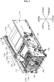
FIG. 2 is a perspective view illustrating main parts of the ATM ofFIG. 1 ; -
FIG. 3 is a plan view illustrating main parts of the ATM ofFIG. 2 ; -
FIGS. 4 to 8 are views illustrating operational states of main parts of the ATM shown inFIG. 2 ; -
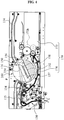
FIG. 9 is a view schematically illustrating an ATM not forming part of the present invention; -
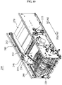
FIG. 10 is a perspective view partially illustrating an upper part ofFIG. 9 ; -
FIG. 11 is a view illustrating a state of a direction guide portion when a rejected paper medium is transferred from a rejected medium transfer portion to a collected medium storage portion shown inFIG. 9 ; and -
FIG. 12 is a view illustrating a state of the direction guide portion when a retracted paper medium is transferred from a carriage to the collected medium storage portion shown inFIG. 9 . - Reference will now be made in detail to embodiments of the present invention, examples of which are illustrated in the accompanying drawings, wherein like reference numerals refer to the like elements throughout. However, the scope of the present invention is not limited to the embodiments.
-
FIG. 1 is a structure view schematically illustrating an automatic teller machine (ATM) 100 according to an embodiment of the present invention.FIG. 2 is a perspective view illustrating main parts of theATM 100 ofFIG. 1 .FIG. 3 is a plan view illustrating main parts of theATM 100 ofFIG. 2 .FIGS. 4 to 8 are views illustrating operational states of main parts of theATM 100 shown inFIG. 2 . - Referring to
FIG. 1 , theATM 100 includes acase 110, amedium storage unit 120, amedium transfer unit 130, amedium inspection unit 140, acarriage 150, arotor 160, and amedium collection unit 170. In the following description, theATM 100 will be limitedly described as a cash dispenser. However, technical aspects of the present invention are applicable to a cash receiver and a combined cash receiver and dispenser. - The
medium storage unit 120 may be disposed at a lower part of thecase 110. Themedium transfer unit 130, themedium inspection unit 140, thecarriage 150, therotor 160, themedium collection unit 170,dispenser portions movement paths case 110. - The
dispenser portions case 110. That is, thedispenser portions front dispenser 111 disposed at a front part of thecase 110, arear dispenser 112 disposed at a rear part of thecase 110, and anupper dispenser 113 disposed at an upper surface of thecase 110. - The
movement paths front movement path 114 disposed between thefront dispenser 111 and therotor 160, arear movement path 115 disposed between therear dispenser 112 and therotor 160, and anupper movement path 116 disposed between theupper dispenser 113 and therotor 160. However, the numbers and the positions of thedispenser portions movement paths ATM 100. - Referring to
FIG. 2 , themovement paths guide rails case 110 to guide a movement direction of thecarriage 150, and rail gears 114b, 115b, and 116b arranged in a length direction of theguide rails guide roller 157 of thecarriage 150 may be movably inserted in theguide rails guide rails gear 158 of thecarriage 150. The movinggear 158 will be described later. - Referring to
FIG. 1 , themedium storage unit 120 is adapted to store paper mediums P. Typically, the paper mediums P may include banknotes, checks, merchandise coupons, tickets, and the like. Hereinafter, the paper mediums P will be described as banknotes for convenience of explanation. - The
medium storage unit 120 may be integrally formed with a lower part of thecase 110. However, in the present embodiment, themedium storage unit 120 will be described to be removably mounted at the lower part of thecase 110. For example, themedium storage unit 120 may be provided in the form of a removable box such as a cassette. The paper mediums P may be stored in themedium storage unit 120. - A plurality of the
medium storage units 120 may be removably mounted at the lower part of thecase 110. The same type or different types of the paper mediums P may be stored in the respective plurality ofmedium storage units 120. - Referring to
FIGS. 1 and2 , themedium transfer unit 130 is adapted to selectively transfer the paper mediums P stored in any one of the plurality ofmedium storage units 120 sheet by sheet. Themedium transfer unit 130 may be disposed between themedium storage unit 120 and therotor 160. Themedium transfer unit 130 may supply the paper mediums P into thecarriage 150 disposed at therotor 160. Themedium transfer unit 130 may include a plurality of rollers and belts. - A
sheet roller 132 may be disposed at an exit of themedium transfer unit 130 to feed the paper mediums P transferred by themedium transfer unit 130 sheet by sheet into thecarriage 150. - Referring to
FIGS. 1 and2 , themedium inspection unit 140 is adapted to detect whether the paper mediums P being transferred by themedium transfer unit 130 are in a normal state, in various methods. For example, themedium inspection unit 140 may use an ultrasonic sensor or a plurality of optical sensors. - In the following description of the present embodiment, the
medium inspection unit 140 detects a change in thickness of the paper mediums P being transferred by themedium transfer unit 130, thereby determining whether a single sheet of the paper mediums P is transferred. For example, themedium inspection unit 140 may include two contact portions disposed in different positions, through which the paper mediums P are passed. A number of sheet of the paper mediums P may be detected by varying positions of the contact portions. In addition, themedium inspection unit 140 may include a plurality of contact portions disposed in respectively different positions to determine skew of the paper mediums P being transferred by themedium transfer unit 130. - Referring to
FIG. 1 , thecarriage 150 is adapted to carry paper mediums P determined to be normal by themedium inspection unit 140 to thedispenser portions medium inspection unit 140 among the paper mediums P being transferred by themedium transfer unit 130 may be temporarily stacked in thecarriage 150. When stacking of the paper mediums P in thecarriage 150 is completed, thecarriage 150 may be moved along any one of themovement paths dispenser portions carriage 150 are dispensed in a bundle. - The
carriage 150 may include afirst carriage portion 152, asecond carriage portion 154, and acarriage driving portion 156. - The
first carriage portion 152 may be provided in the form of a panel to tightly contact one surface of the paper medium P. When thecarriage 150 is disposed inside therotor 160, thefirst carriage portion 152 may be rotated along with therotor 160 as therotor 160 is rotated. During the operation of themedium transfer unit 130, the paper mediums P may be stacked on one surface of thefirst carriage portion 152. To move the stacked paper mediums P in a bundle, thefirst carriage portion 152 may include afirst transfer belt 152a and afirst transfer pulley 152b disposed at one side of thefirst carriage portion 152. - In addition, a
guide roller 157 and a movinggear 158 may be disposed at opposite lateral sides of thefirst carriage portion 152, respectively. Theguide roller 157 may be a roller member disposed in and moved along theguide rails gear 158 may be engaged with the rail gears 114b, 115b, and 116b and move along with the rail gears 114b, 115b, and 116b when rotated. The movinggear 158 may be a pinion gear rotated in engagement with the rail gears 114b, 115b, and 116b implemented by rack gears. Since theguide roller 157 and the movinggear 158 are separated from each other, being disposed at the opposite lateral sides of thefirst carriage portion 152, thecarriage 150 may be stably supported by theguide roller 157 and the movinggear 158. In addition, thecarriage 150 may be moved along the rail gears 114b, 115b, and 116b by the movinggear 158. - The
second carriage portion 154 may be provided in the form of a panel to tightly contact the other surface of the paper mediums P. Thesecond carriage portion 154 may be foldably connected to thecarriage driving portion 156 to be in tight contact with the one surface of thefirst carriage portion 152. Therefore, one surface of thesecond carriage portion 154 may be brought into tight contact with the other surface of the paper mediums P stacked on the one surface of thefirst carriage portion 152. Here, thefirst carriage portion 152 and thesecond carriage portion 154 may include an elastic member (not shown) applying an elastic force in a direction for bringing thesecond carriage portion 154 into tight contact with thefirst carriage portion 152. Thesecond carriage portion 154 may include asecond transfer belt 154a and asecond transfer pulley 154b disposed at one side of thesecond carriage portion 154 to move the paper mediums P stacked on the one surface of thefirst carriage portion 152 in a bundle. Here, thesecond transfer belt 154a and thefirst transfer belt 152a may be disposed to face each other. - An
opening projection 159 may be formed at one side of thesecond carriage portion 154. The opening projection 135 is a member to restrict rotation of thesecond carriage portion 154 by being interfered with thecase 110 or themedium transfer unit 130 when therotor 160 rotates. That is, when therotor 160 rotates along with thecarriage 150 in a direction toward themedium transfer unit 130, the opening projection 135 may be interfered with thecase 110 or themedium transfer unit 130, thereby restricting rotation of thesecond carriage portion 154. Therefore, even while thesecond carriage portion 154 is stopped by the opening projection 135, since thefirst carriage portion 152 may continue rotating along with therotor 160, a gap between thefirst carriage portion 152 and thesecond carriage portion 154 may be widened by a rotational force of therotor 160. - The
carriage driving portion 156 may be connected with thefirst carriage portion 152 and thesecond carriage portion 154 to foldably support thefirst carriage portion 152 and thesecond carriage portion 154. That is, when the gap between thefirst carriage portion 152 and thesecond carriage portion 154 is widened, the paper mediums P transferred by themedium transfer unit 130 may be stacked on the one surface of thefirst carriage portion 152. Conversely, when thefirst carriage portion 152 and thesecond carriage portion 154 are folded to each other, the paper mediums P may be stably fixed in a bundle form between the one surface of thefirst carriage portion 152 and the one surface of thesecond carriage portion 154. - In addition, the
carriage driving portion 156 may supply a driving force to the movinggear 158, thefirst transfer belt 152a, and thesecond transfer belt 154a. That is, thecarriage driving portion 156 may include a first carriage driving portion (not shown) to drive the movinggear 158 in connection with the movinggear 158, and a second carriage driving portion (not shown) to drive thefirst transfer belt 152a and thesecond transfer belt 154a in connection with thefirst transfer pulley 152b and thesecond transfer pulley 154b. Therefore, when thefirst transfer belt 152a and thesecond transfer belt 154a are driven by thecarriage driving portion 156 in a state where thefirst carriage portion 152 and thesecond carriage unit 154 are folded, the paper mediums P disposed between thefirst carriage portion 152 and thesecond carriage portion 154 may be withdrawn out of thecarriage 150 by a predetermined length. - The
carriage driving portion 156 may be connected to a controller (not shown) of theATM 100 in various manners. Operations of thefirst carriage portion 152 and thesecond carriage portion 154 may be properly controlled by the controller. Various methods may be used to connect thecarriage driving portion 156 and the controller according to the design and conditions of theATM 100. For example, thecarriage driving portion 156 may be connected to the controller by an elongated cable or elastic cable, or using theguide rails guide roller 157. - The
rotor 160 may be disposed in thecase 110 to be rotatable so as to convert a withdrawing direction of thecarriage 150. That is, thecarriage 150 may be withdrawably inserted in therotor 160. - The
rotor 160 may change a position of thecarriage 150 to be directed to any one of themedium transfer unit 130, thefront movement path 114, therear movement path 115, theupper movement path 116, or a retractbox 180 that will be described later. Therotor 160 may be rotated to any one of a first position, second positions, and a third position. In the first position, the paper mediums P are stacked in thecarriage 150 by themedium transfer unit 130. In the second positions, the paper mediums P may be withdrawn to any one of thefront movement path 114, therear movement path 115, and theupper movement path 116. In the third position, the paper mediums P may be inserted in an entrance of the retractbox 180 by thecarriage 150. - Here, when the
rotor 160 is in the first position, thefirst carriage portion 152 and thesecond carriage portion 154 may be separated from each other. That is, when therotor 160 is rotated toward the first position, the openingprojection 159 is interfered with thecase 110 or themedium transfer unit 130, thereby restricting rotation of thesecond carriage portion 154. When thefirst rotor 160 is further rotated to the first position, thefirst carriage portion 152 continues rotating along with therotor 160 while rotation of thesecond carriage portion 154 is restricted. Accordingly, the gap between thefirst carriage portion 152 and thesecond carriage portion 154 is widened, thereby forming a stacking space to stack the paper mediums P. - When the
rotor 160 is disposed in other than the first position, thefirst carriage portion 152 and thesecond carriage portion 154 are folded to each other. That is, when therotor 160 is rotated from the first position to other positions, thefirst carriage portion 152 may come into tight contact with thesecond carriage portion 154 and then thefirst carriage portion 152 and thesecond carriage portion 154 may be rotated in the folded state. As a result, the paper mediums stacked in the stacking space may be stably fixed. - The
rotor 160 may includerotation portions 162 and a connectingportion 164. However, therotor 160 may be configured in various forms according to the design and conditions of theATM 100. - The
rotation portions 162 may be rotatably mounted at opposite lateral sides of thecase 110 and may be provided in a disc form. Acarriage movement path 162a may be formed on an inner surface of eachrotation portion 162 in the same shape as themovement paths carriage 150. Theguide roller 157 and the movinggear 158 formed at the opposite lateral sides of thecarriage 150 may be disposed on thecarriage movement path 162a. Also, thecarriage movement path 162a may be opened toward an outer circumference of therotation portion 162 so that thecarriage 150 may be withdrawn out of therotor 160. Therefore, when therotor 160 is disposed in the second positions, thecarriage movement path 162a is corresponded to any one of thefront movement path 114, theupper movement path 116, and therear movement path 115, thereby enabling movement of thecarriage 150. - The connecting
portion 164 is a plate member of which opposite sides are connected to therotation portions 162 disposed at the opposite lateral sides of thecase 110. Therefore, therotation portions 162 disposed at the opposite lateral sides of thecase 110 may be integrally rotated by the connectingportion 164. In addition, thecarriage 150 disposed in therotor 160 may be stably mounted. - Referring to
FIG. 1 , themedium collection unit 170 is adapted to collect paper mediums P determined to be abnormal by themedium inspection unit 140, along a path bypassing thecarriage 150 and therotor 160. Themedium collection unit 170 may be disposed in thecase 110. - The
medium collection unit 170 may include areject box 172 to receive the paper mediums P determined to be abnormal by themedium inspection unit 140, and areject transfer portion 174 including a path bypassing therotor 160 and thecarriage 150 between thereject box 172 and themedium transfer unit 130 and transferring the paper mediums P to thereject box 172. - Accordingly, the paper mediums P determined to be abnormal by the
medium inspection unit 140 may be not stacked in thecarriage 150 but collected in thereject box 172 along thereject transfer portion 174. Since the operation of themedium transfer unit 130 is not stopped during this, stacking of the paper mediums P in thecarriage 150 may be continued. - The
reject box 172 refers to a box member configured to store a plurality of the paper mediums P determined to be abnormal by themedium inspection unit 130. An entrance of thereject box 172 may be directed to therotor 160. Additionally,rotatable roller members 172b may be provided at theentrance 172a of thereject box 172 to guide the paper mediums P into thereject box 172. - The
reject transfer portion 174 guides the paper mediums P determined to be abnormal by themedium inspection unit 140 into thereject box 172 from themedium transfer unit 130. Thereject transfer portion 174 may be formed as a path bypassing therotor 160 and themovement paths rotor 160 and thecarriage 150. Thereject transfer portion 174 may include a belt and a pulley, in the same manner as themedium transfer unit 130. Hereinafter, thereject transfer portion 174 according to the embodiment will be described to be in a parabola shape concave down along a lower part of therotor 160. - Referring to
FIG. 1 , agate member 134 may be provided among an exit of themedium inspection unit 140, therotor 160, and an entrance of thereject transfer portion 174 to guide the paper medium transferred by themedium transfer unit 130 to thecarriage 150 disposed in therotor 160 or to the reject transfer portion according to a detection value of themedium inspection unit 140. Thegate member 134 may convert a transfer direction of the paper mediums P according to the detection value of themedium inspection unit 140. That is, when thegate member 134 is rotated in one direction, the paper mediums P transferred by themedium transfer unit 130 may be transferred to thecarriage 150 disposed in therotor 160. When thegate member 134 is rotated in another direction, the paper mediums P transferred by themedium transfer unit 130 may be transferred to the entrance of thereject transfer portion 174. - Referring to
FIG. 1 , theATM 100 may further include the retractbox 180 to store paper mediums P collected from thedispenser portions dispenser portions box 180 may be disposed in thecase 110 such that the entrance of the retractbox 180 is directed to therotor 160.. In the present embodiment, the retractedbox 180 is disposed in thereject box 172. Accordingly, space utilization of thecase 110 may be further improved. - When the
rotor 160 is rotated toward the entrance of the retractbox 180 and disposed in the third position, thecarriage 150 may be withdrawn to the entrance of the retractbox 180. In addition, the paper mediums P may be inserted in the retractbox 180 by thecarriage 150. - The retract
box 180 may be disposed in thereject box 172 to be movable or rotatable toward theentrance 172a of thereject box 172. That is, when the paper mediums P in a bundle not received by thedispenser portions entrance 172a of thereject box 172, theentrance 180a of the retractbox 180 may be moved or rotated to theentrance 172a of thereject box 172. Therefore, the paper mediums P introduced through theentrance 172a of thereject box 172 may be stacked in the retractbox 180. In the present embodiment, a lower part of the retractbox 180 will be described to be rotatably hinged to a lower part of thereject box 172 and to be rotated about a hinge shaft by a separate driving portion (not shown). - Referring to
FIG. 1 , theATM 100 may further include amain driving portion 190 disposed in thecase 110 to provide a driving force to themedium transfer unit 130 and themedium collection unit 170. That is, themedium transfer unit 130, thereject transfer portion 174, and thereject roller 172b of thereject roller 172 may be driven together by the driving force of themain driving portion 190. Meanwhile, therotor 160 may be controlled independently by aseparate driving portion 192. - Hereinafter, the operational process of the above-structured
ATM 100 will be described. - First, the
medium transfer unit 130 receives a sheet of paper medium P from any one of themedium storage units 120 and transfers the sheet to therotor 160. Here, themedium inspection unit 140 detects the paper medium P being transferred along themedium transfer unit 130 and determines whether the paper medium P is in a normal state. That is, themedium inspection unit 140 detects whether the paper medium P being transferred along themedium transfer unit 130 includes double sheets or is skewed. When the paper medium P includes double sheets or is skewed, themedium inspection unit 140 determines the paper medium P to be in an abnormal state. - Referring to
FIG. 4 , therotor 160 rotates to the first position and disposes thecarriage 150 to be directed to the exit of themedium transfer unit 130. When therotor 160 is thus rotated, the openingprojection 159 formed at thesecond carriage portion 154 of themedium transfer unit 130 is interfered with themedium transfer unit 130 or thecase 110, thereby restricting rotation of thesecond carriage portion 154. However, in this state, since thefirst carriage portion 152 of themedium transfer unit 130 is still rotated along with therotor 160, thefirst carriage portion 152 and thesecond carriage portion 154 are moved away from each other as therotor 160 rotates, thereby forming a stacking space to stack the paper mediums. - When the paper medium P is determined to be normal by the
medium inspection unit 140, thegate member 134 is operated in one direction, thereby guiding the paper medium P to therotor 160. In this instance, thesheet roller 132 stacks the paper medium P in the stacking space of thecarriage 150. Accordingly, a plurality of the paper mediums P may be vertically stacked in thecarriage 150. - Referring to
FIGS. 5 to 7 , when a desired number of sheets of the paper mediums P are stacked in thecarriage 150, therotor 160 may be rotated from the first position to the second positions. In addition, thefirst carriage portion 152 rotated along with therotor 160 may be folded to thesecond carriage portion 154. Accordingly, the paper mediums P in a bundle may be stably fixed by thefirst carriage portion 152 and thesecond carriage portion 154. - Next, the
rotor 160 is rotated to one of the second positions according to positions of thedispenser portions - As shown in
FIG. 5 , when therotor 160 is rotated to a position where thecarriage movement path 162a of therotor 160 and thefront movement path 114 fluidly communicate, thecarriage 150 in therotor 160 may be moved to thefront dispenser portion 111 along thecarriage movement path 162a and thefront movement path 114. Also, thefirst transfer belt 152a and thesecond transfer belt 154a of thecarriage 150 moved to thefront dispenser portion 111 may be driven. Therefore, the paper mediums P are withdrawn to a front portion of thecase 110 through thefront dispenser portion 111. - As shown in
FIG. 6 , when therotor 160 is rotated to a position where thecarriage movement path 162a of therotor 160 and theupper movement path 116 fluidly communicate, thecarriage 150 in therotor 160 is moved to theupper dispenser portion 113 along thecarriage movement path 162a and theupper movement path 116. Also, thefirst transfer belt 152a and thesecond transfer belt 154a of thecarriage 150 moved to theupper dispenser portion 113 may be driven. Therefore, the paper mediums P are withdrawn to an upper part of thecase 110 through theupper dispenser portion 113. - As shown in
FIG. 7 , when therotor 160 is rotated to a position where thecarriage movement path 162a of therotor 160 and therear movement path 115 fluidly communicate, thecarriage 150 in therotor 160 is moved to therear dispenser portion 112 along thecarriage movement path 162a and therear movement path 115. Also, thefirst transfer belt 152a and thesecond transfer belt 154a of thecarriage 150 moved to therear dispenser portion 112 may be driven. Therefore, the paper mediums P are withdrawn to a rear portion of thecase 110 through therear dispenser portion 112. - When the paper mediums P dispensed through the
dispenser portions first transfer belt 152a and thesecond transfer belt 154a of thecarriage 150 are rotated backward to thereby collect the paper mediums p in a bundle into thecarriage 150. In addition, thecarriage 150 may return to the inside of therotor 160 along themovement paths carriage movement path 162a. - Referring to
FIG. 8 , therotor 160 to which thecarriage 150 returns is rotated to the third position. Accordingly, thecarriage 150 may be disposed toward theentrance 162a of thereject box 172 of themedium collection unit 170. In addition, after thecarriage 150 is withdrawn along thecarriage movement path 162a, thefirst transfer belt 152a and thesecond transfer belt 154a of thecarriage 150 are rotated forward, thereby inserting the paper mediums P in a bundle into theentrance 172a of thereject box 170. - In this instance, the retract
box 180 may be rotated toward theentrance 172a of thereject box 172, and thereject roller 172b provided at theentrance 172a of thereject box 172 may be driven. Therefore, thereject roller 172b may collect the paper mediums P inserted in theentrance 172a of thereject box 172 and guide the paper mediums P to theentrance 180a of the retractbox 180. When the paper mediums P are put into the retractbox 180, the retractbox 180 is returned to an initial position. In addition, thecarriage 150 is returned into therotor 160, and therotor 160 is rotated to the first position. - When the paper mediums P are determined to be abnormal by the
medium inspection unit 140, thegate member 134 is operated, thereby guiding the abnormal paper mediums P toward thereject transfer portion 174. Then, thereject transfer unit 174 transfers the abnormal paper mediums P to theentrance 172a of thereject box 172, and thereject roller 172b collects the paper mediums P transferred to theentrance 172a of thereject box 172 so that the paper mediums P are received in thereject box 172. Thus, the operation of collecting the paper mediums P determined to be abnormal into thereject box 172 may be independently performed from the operations of thecarriage 150 and therotor 160. -
FIG. 9 is a view schematically illustrating anATM 200 not forming part of the present invention.FIG. 10 is a perspective view partially illustrating an upper part ofFIG. 9 .FIG. 11 is a view illustrating a state of adirection guide portion 280 when a rejected paper medium is transferred from a rejectedmedium transfer portion 260 to a collectedmedium storage portion 270 shown inFIG. 9 , andFIG. 12 is a view illustrating a state of thedirection guide portion 280 when a retracted paper medium is transferred from a carriage to the collectedmedium storage portion 270 shown inFIG. 9 . - Referring to
FIGS. 9 and10 , theATM 200 may include amedium storage portion 210 to store paper mediums P, amedium transfer portion 220 to transfer the paper mediums P supplied from themedium storage portion 210, amedium carrier 230 to carry the paper mediums P transferred by themedium transfer portion 220 to a dispenser portion (not shown), acarrier transfer portion 240 which forms a movement path for themedium carrier 230 to move to the dispenser portion, a carrierposition adjustment portion 250 to adjust a position of themedium carrier 230, the rejectedmedium transfer portion 260 connected to a rear end of themedium transfer portion 220 to transfer a paper medium P detected to be abnormal during transfer along themedium transfer portion 220 and determined to be rejected, and the collectedmedium storage portion 270 disposed within a movement range of themedium carrier 230 to collect a paper medium P not received by the dispenser portion but retracted or collect the rejected paper medium P transferred along the rejectedmedium transfer portion 260. - According to the aforementioned structure, a normal paper medium, that is, the paper medium P not detected to be abnormal, may be transferred to the dispenser portion from the
medium storage portion 210. Meanwhile, the paper medium P detected to be abnormal and rejected may be transferred to the collectedmedium storage portion 270 by the rejectedmedium transfer portion 260. Also, a paper medium P dispensed but not received, and therefore retracted, may be transferred to the collectedmedium storage portion 270. That is, the rejected paper medium P and the retracted paper medium P are transferred to and stored in the same storage place, that is, the collectedmedium storage portion 270. Therefore, the overall structure may be simplified while reducing an installation space and cost. - The respective parts will be described. The
medium storage portion 210 may store the paper mediums P. The paper mediums P may include banknotes, checks, merchandise coupons, tickets, and the like. Themedium storage portion 210 may be provided in the form of a cassette removably connected to a plurality of receivingspaces 210S arranged in a height direction in theATM 200. Therefore, the paper mediums P may be stored in themedium storage portion 210. As themedium storage portion 210 is selectively connected to an inside of theATM 200, the paper mediums P may be supplied to or withdrawn from the inside of theATM 200. - The
medium transfer portion 220 is adapted to transfer the paper mediums P stored in themedium storage portion 210 sheet by sheet. As shown inFIGS. 9 and10 , themedium transfer portion 220 may be disposed between themedium storage portion 210 and the carrierposition adjustment portion 250, to feed the paper mediums P in themedium carrier 230 disposed at the carrierposition adjustment portion 250. Themedium transfer portion 220 may include a plurality of rollers and belts for transferring the paper mediums P. That is, as the rollers are rotated, the belts are circulated, thereby transferring the paper mediums P. - In addition, the
medium transfer portion 220 may include amedium sensor 222 to detect whether the paper medium P being transferred from themedium storage portion 210 is a single sheet. That is, themedium sensor 222 may detect a thickness change of the paper mediums P being transferred by themedium transfer portion 220, thereby determining whether the paper medium P is a single sheet. In addition, a sheet roller (not shown) may be provided at an exit of themedium transfer portion 220 to feed the paper mediums P transferred by themedium transfer portion 220 sheet by sheet into themedium carrier 230. - The
medium carrier 230 is adapted to stack and carry at least one sheet of the paper mediums P transferred by themedium transfer portion 220. A medium stacked in themedium carrier 230 may include a single sheet or plural sheets of the paper mediums P. - The
medium carrier 230 may include afirst carrier portion 231 and asecond carrier portion 232 capable of moving toward or away from thefirst carrier portion 231. Thefirst carrier portion 231 and thesecond carrier portion 232 are provided in a panel form. Since thesecond carrier portion 232 may approach thefirst carrier portion 231, the paper mediums P may be fixed within thefirst carrier portion 231 and thesecond carrier portion 232. - The above-structured
medium carrier 230 may be transferred to the dispenser portion along thecarrier transfer portion 240. Thecarrier transfer portion 240 may be formed between the dispenser portion and the carrierposition adjustment portion 250 that will be described later. Thecarrier transfer portion 240 may include a rail structure to enable transfer of an entire part of themedium carrier 230. - Hereinafter, the
ATM 200 according to the present embodiment will be described to include a plurality of the dispenser portions and accordingly include a plurality of thecarrier transfer portions 240. For example, the dispenser portions are disposed at a front part, a rear part, and an upper part of theATM 200. Accordingly, thecarrier transfer portions 240 may include a frontcarrier transfer portion 242 connected to the dispenser portion provided at the front part, a rearcarrier transfer portion 244 connected to the dispenser portion provided at the rear part, and an uppercarrier transfer portion 246 connected to the dispenser portion provided at the upper part. - The
carrier position adjustment 250 may change the position of themedium carrier 230 as shown inFIG. 9 . That is, thecarrier position adjustment 250 may rotate themedium carrier 230, thereby changing the position of themedium carrier 230 so that an open portion of themedium carrier 230 is directed to any one of the exit of themedium transfer portion 220, an entrance of the frontcarrier transfer portion 242, an entrance of the rearcarrier transfer portion 244, an entrance of the uppercarrier transfer portion 246, and an entrance of the collectedmedium storage portion 270 that will be described later. - Furthermore, the carrier
position adjustment portion 250 may transfer themedium carrier 230 along thecarrier transfer portions 240 as well as changing the position of themedium carrier 230 in a rotating manner. Therefore, themedium carrier 230 may be transferred to the respective dispenser portions and accordingly supply the paper mediums P in themedium carrier 230 to the dispenser portions. - The structure of the carrier
position adjustment portion 250 will be further described. As shown inFIG. 9 , the carrierposition adjustment portion 250 may include aplate 252 to which themedium carrier 230 may be mounted. Also, the carrierposition adjustment portion 250 may include arotor 251 rotatable along with themedium carrier 230 and a rotor driving portion (not shown) to drive therotor 251. According to the foregoing structure, the carrierposition adjustment portion 250 may adjust the position. - As aforementioned, according to related arts, a storage portion to store rejected paper medium and a storage portion to store retracted paper medium are separately formed, thereby complicating the structure and increasing the installation space and cost.
- Therefore, to remove such limits of the related arts, the
ATM 200 may include one collectedmedium storage portion 270, the rejectedmedium transfer portion 260 disposed between themedium transfer portion 220 and the collectedmedium storage portion 270 to transfer the paper mediums P detected to be abnormal during transfer along themedium transfer portion 220 and determined to be rejected, to the collectedmedium storage portion 270, and thedirection guide portion 280 disposed at a rear end of the rejectedmedium transfer portion 260 to transfer the rejected paper medium P to a collected medium or the retracted paper medium P transferred by the medium carrier to the collectedmedium storage portion 270. - According to the foregoing structure, a discharge path for the paper medium P being discharged from the rejected
medium transfer portion 260 to the collectedmedium storage portion 270 and a discharge path for the paper medium P being discharged from themedium carrier 230 to the collectedmedium storage portion 270 are formed in a common discharge space S. Therefore, not only the rejected paper medium P but also the retracted paper medium P may be stored in one place, that is, the collectedmedium storage portion 270. Consequently, the structure may be simplified while the installation space and the cost are also reduced. - The respective parts will be described. First, the collected
medium storage portion 270 is adapted to collect the paper mediums P dispensed by the dispenser portions but not received, and therefore retracted, or the paper mediums P determined to be rejected during transfer along themedium transfer portion 220. The collectedmedium storage portion 270 may be a cassette type to be easily connected to and detached from theATM 200. - As schematically shown in
FIG. 9 , the collectedmedium storage portion 270 may include a collectingcase 271, a retractedmedium storage box 272 disposed at a front end of the collectingcase 271 to store the retracted paper medium P, a rejectedmedium storage box 273 disposed at a rear end of the retractedmedium storage box 272 to store the rejected paper medium P, and arotation roller unit 275 disposed at an entrance of the collectingcase 271 to introduce the rejected or retracted paper medium P into the collectingcase 271. - First, the collecting
case 271 may have a box shape and include the entrance in a position facing a rear end of the rejectedmedium transfer portion 260 and the carrierposition adjustment portion 250. The collectingcase 271 may have a locking structure so that only an authorized user may open and close. - In the present embodiment, the retracted
medium storage box 272 and the rejectedmedium storage box 273 may be separately provided within the collectingcase 271. Therefore, the respective paper mediums P may be introduced and stored in the respective spaces. However, not limited to the foregoing structure, the retractedmedium storage box 272 and the rejectedmedium storage box 273 may be integrally formed and commonly used. - The
rotation roller unit 275 is adapted to transfer the rejected or retracted paper medium P into the collectingcase 271 by rotating. - As shown in
FIG. 9 in detail, therotation roller unit 275 may include anupper roller portion 276 which includes a driving gear (not shown) rotated by a driving force supplied from the outside and a plurality ofrotation rollers 278 arranged in a length direction of arotational axis 276S, and alower roller portion 277 which includes a driven gear (not shown) meshed with the driving gear of theupper roller portion 276 and a plurality ofrotation rollers 278 arranged in a length direction of arotational axis 277S. - According to the foregoing structure, as shown in
FIGS. 11 and12 , when the driving gear of theupper roller portion 276 rotates counterclockwise, the driven gear of thelower roller portion 277 is rotated clockwise. Therefore, the rejected or retracted paper medium P may be passed through the entrance of the collectingcase 271 and introduced into the collectingcase 271. - Here, the
rotation rollers 278 of theupper roller portion 276 and therotation rollers 278 of thelower roller portion 277 may be substantially the same. Therotation rollers 278 may be made of an elastic material contractible inward as the plurality of paper mediums P are introduced and deformable to press the paper mediums P. - The rejected
medium transfer portion 260 may be connected to themedium transfer portion 220 with one end and connected to the entrance of the collectedmedium storage portion 270 with a rear end, as shown inFIG. 9 . Accordingly, the paper mediums P transferred from themedium transfer portion 220 may be passed through the rejectedmedium transfer portion 260 and stored in the collectedmedium storage portion 270. - In addition, the rejected
medium transfer portion 260 may be disposed at a lower part of the carrierposition adjustment portion 250. Therefore, although the paper mediums P are jammed in a transfer path of the rejectedmedium transfer portion 260, removal of the paper mediums P may be easily achieved. - The structure of the rejected
medium transfer portion 260 will be described in further detail. As shown inFIG. 9 , the rejectedmedium transfer portion 260 may include a lower conveyingportion 261 in a conveyer form which is connected to the rear end of themedium transfer portion 220 with one end, and connected to a position adjacent to the collectedmedium storage portion 270 with the other end, and an upper conveyingportion 262 disposed at an upper part of the lower conveyingportion 261. - By the aforementioned structure, the paper mediums P introduced between the upper conveying
portion 262 and the lower conveyingportion 261 may be smoothly moved and introduced into the collectedmedium storage portion 270. - However, as aforementioned, a jam of the paper mediums P may occur during transfer of the paper mediums P along the rejected
medium transfer portion 260. - To solve this, the upper conveying
portion 262 may have a width smaller than a width of the lower conveyingportion 261. More specifically, the width of the upper conveyingportion 262 is smaller than the width of the lower conveyingportion 261 and also smaller than a width of the paper mediums P. - Therefore, although the paper mediums P are jammed, access to the paper mediums P jammed in the upper conveying
portion 262 and the lower conveyingportion 261 may be enabled by adjusting the position of the carrierposition adjustment portion 250. Thus, the paper mediums P jammed in the upper conveyingportion 262 and the lower conveyingportion 261 may be easily removed. - As shown in
FIGS. 11 and12 , thedirection guide portion 280 may be disposed to be rotatable at the rear end of the rejectedmedium transfer portion 260, so as to guide an advancing direction of the paper mediums P. - As shown in
FIGS. 11 and12 , thedirection guide portion 280 may include aguide body 281 rotatably connected at a rear end area of the rejectedmedium transfer portion 260 to guide the advancing direction of the paper mediums P, and arotational axis 282 to enable axial rotation of theguide body 281. - The
guide body 281 may include a curve surface corresponding to a rear end of the lower conveyingportion 261 of the rejectedmedium transfer portion 260, as shown inFIG. 11 . A lower surface of theguide body 281 may guide the paper mediums P in an arrowed direction A inFIG. 11 when the paper mediums P are transferred from the rejectedmedium transfer portion 260 to the collectedmedium storage portion 270. An upper surface of theguide body 281 guides the paper mediums P in an arrowed direction B inFIG. 12 when the paper mediums P are transferred from themedium carrier 230 to the collectedmedium storage portion 270. - The
guide body 281 adjusts its position between a reject discharge position forming a transfer path connecting the rejectedmedium transfer portion 260 to the entrance of the collected medium storage portion 270 (the position of theguide body 281 inFIG. 11 ) and a retract discharge position forming a transfer path connecting themedium carrier 230 to the entrance of the collected medium storage portion 270 (the position of theguide body 281 inFIG. 12 ). - For example, when the paper mediums P are transferred along the rejected
medium transfer portion 260, theguide body 281 is pressed by the paper mediums P, thereby forming the transfer path connecting the rejectedmedium transfer portion 260 to the collectedmedium storage portion 270 as shown inFIG. 11 . Therefore, the paper mediums P may be introduced into the collectedmedium storage portion 270 along the transfer path. - Conversely, when the paper mediums P not received by the dispenser portions but retracted are discharged from the
medium carrier 230 and presses theguide body 281, theguide body 281 may be rotated to the retract discharge position as shown inFIG. 12 , accordingly forming the transfer path for the paper mediums P being transferred from themedium carrier 230 to the collectedmedium storage portion 270. Here, when theguide body 281 is disposed in the retract discharge position, theguide body 281 may prevent escape of the paper mediums P while guiding transfer of the paper mediums P. - In the present embodiment, to increase accessibility of the
medium carrier 230 with respect to the collectedmedium storage portion 270 when the paper mediums P are discharged from themedium carrier 230 to the collectedmedium storage portion 270, the carrierposition adjustment portion 250 may further include acarrier guide 257 directed to the entrance of the collectedmedium storage portion 270 as shown inFIGS. 11 and12 . - The
medium carrier 230 holding the retracted paper medium P may be rotated by operating the carrierposition adjustment portion 250 and then moved toward the collectedmedium storage portion 270 along thecarrier guide 257, thereby accessing the collectedmedium storage portion 270. Accordingly, the paper mediums P discharged from themedium carrier 230 may be smoothly introduced into the inner space of the collectedmedium storage portion 270 through therotation roller unit 275 mounted at the entrance of the collectedmedium storage portion 270. - In addition, referring to
FIGS. 11 and12 , rotation guides 290 rotating in respective original positions are arranged at the entrance area of the collectedmedium storage portion 270, more specifically, between therotation rollers 278 of theupper roller portion 276. - The rotation guides 290 may be operated in association with the
guide body 281. For example, when theguide body 281 is disposed in the reject discharge position so as to discharge the paper mediums P from the rejectedmedium transfer portion 260 to the collectedmedium storage portion 270, the rotation guides 290 may be maintained in a state of being pivoted down as shown inFIG. 11 . Accordingly, the paper mediums P discharged from the rejectedmedium transfer portion 260 to the entrance of the collectedmedium storage portion 270 may be slightly collided with therotation guide 290 and then introduced into therotation roller unit 275. That is, the rotation guides 290 may prevent escape of the paper mediums P while guiding transfer of the rejected paper medium P being introduced into the collectedmedium storage portion 270. - Conversely, when the
guide body 281 is disposed in the retract discharge position so as to discharge the paper mediums P from themedium carrier 230 to the collectedmedium storage portion 270, the rotation guides 290 may be maintained in a state of being pivoted up as shown inFIG. 12 , thereby guiding transfer of the paper mediums P from themedium carrier 230 to the entrance of the collectedmedium storage portion 270. - Hereinafter, the operation of the
ATM 200 structured as aforementioned will be described. - First, the paper mediums P are fed sheet by sheet from the
medium storage portion 210 to themedium transfer portion 220, and themedium transfer portion 220 transfers the paper mediums P to themedium carrier 230. In this instance, themedium sensor 222 may detect whether the paper mediums P are in a normal or abnormal state. The paper medium P detected to be abnormal and determined to be rejected may be transferred to the collectedmedium storage portion 270 along the rejectedmedium transfer portion 260. - Here, when the paper mediums P are transferred from the rejected
medium transfer portion 260 to the collectedmedium storage portion 270, thedirection guide portion 280 mounted to the rear end of the rejectedmedium transfer portion 260 may be disposed in the reject discharge position, that is, the position of theguide body 281 as shown inFIG. 11 . Therefore, the rejected paper medium P may be smoothly introduced from the rejectmedium transfer portion 260 to the collectedmedium storage portion 270. - The paper medium P detected to be normal by the
medium sensor 222 may be carried to themedium carrier 230 and supplied to the dispenser portions by the carrierposition adjustment portion 250. Here, the paper medium P supplied to the dispenser portions may be not received but retracted. In this case, the retracted paper medium P may be carried by themedium carrier 230 and transferred to the collectedmedium storage portion 270. - Here, when the paper mediums P are transferred from the
medium carrier 230 to the collectedmedium storage portion 270, thedirection guide portion 280 may be disposed in the retract discharge position, that is, the position of theguide body 281 as shown inFIG. 12 . Therefore, the retracted paper medium P may be smoothly introduced from themedium carrier 230 into the collectedmedium storage portion 270. - Thus, according to the present embodiment, the paper medium P detected to be abnormal during transfer along the
medium transfer portion 220 and determined to be rejected and the paper medium P not received by the dispenser portion but retracted may be collected to one space, that is, the collectedmedium storage portion 270. As a result, the overall structure may be simplified, thereby reducing the size and cost of the apparatus. - Although an embodiment of the present invention has been shown and described, the present invention is not limited to the described embodiment . Instead, it would be appreciated by those skilled in the art that changes may be made to this embodiment without departing from the scope of the invention, which is solely defined by the appended claims.
Claims (9)
- An automatic teller machine ATM (100) comprising:a case (110) in which a plurality of dispenser portions (111, 112. 113) are disposed in different positions;a medium storage unit (120) provided to the case (110) to store paper mediums;a medium transfer unit (130) to transfer the paper mediums sheet by sheet from the medium storage unit (120);a medium inspection unit (140) provide to the medium transfer unit (130) to detect the paper mediums being transferred by the medium transfer unit (13 0) ;a carriage (150) in which paper mediums determined to be normal by the medium inspection unit (140) are stacked, the carriage (150) configured to be transferred along any one of movement paths (114, 115, 116) connected to the plurality of dispenser portions (111, 112, 113) to dispense the paper mediums through any one of the plurality of dispenser portions (111, 112, 113);characterized bya rotor (160) in which the carriage (150) is withdrawably inserted, the rotor (160) rotatably mounted in the case (110) and rotated along with the carriage (150) in any position between a first position in which the paper mediums are stacked in the carriage (150) and a second position in which the carriage (150) is moved to the movement paths (114, 115, 116); anda medium collection unit (170) disposed in the case (110) such that paper mediums determined to be abnormal by the medium inspection unit (140) are collected along a path bypassing the carriage (150) and the rotor (160 ).
- The ATM (100) of claim 1, wherein
the plurality of dispenser portions (111, 112, 113) comprises a front dispenser portion (111) disposed on a front portion of the case (110), a rear dispenser disposed at a rear portion (112) of the case (110), and an upper dispenser (113) disposed at an upper surface of the (110) case, and
the movement paths (114, 115, 116) comprise a front movement path (114) disposed between the front dispenser (111) and the rotor (160), a rear movement path (115) disposed between the rear dispenser (112) and the rotor (160) and an upper movement path (116) disposed between the upper dispenser (113) and the rotor (160). - The ATM (100) of claim 1, wherein
the movement paths (114, 115, 116) each comprise guide rails (114a, 115a, 116a) disposed on opposite lateral sides of the case (110) to guide a movement direction of the carriage (150), and rail gears (114b, 115b, 116b) arranged in a length direction of the guide rails (114a, 115a, 116a), and
the carriage (150) comprises guide rollers (157) disposed on opposite lateral sides to be moved along the guide rails (114a, 115a, 116a), respectively, and moving gears (158) disposed on the opposite lateral sides to be engaged with and moved along the rail gears (114b, 115b, 116b), respectively. - The ATM (100) of claim 3, wherein the carriage (150) comprises:a first carriage portion (152) provided with the guide rollers (157) and the moving gears (158) disposed on the opposite lateral sides, and rotated along with the rotor (160) when the rotor (160) rotates;a second carriage portion (154) disposed to face the first carriage portion (152) such that the paper mediums are disposed between the first carriage portion (152) and the second carriage portion (154); anda carriage driving portion (156) to which the first carriage portion (152) and the second carriage portion (154) are foldably connected, the carriage driving portion (156) configured to drive the moving gears (158).
- The ATM (100) of claim 4, wherein
the first carriage portion (152) comprises a first transfer belt (152a) tightly contacting one surface of the paper mediums,
the second carriage portion (154) comprises a second transfer belt (154a) tightly contacting the other surface of the paper mediums, and
the first transfer belt (152a) and the second transfer belt (154a) are driven by the carriage driving portion (156). - The ATM (100)
of claim 5, wherein the carriage driving portion (156) comprises:a first carriage driving portion connected to the moving gear (158) to drive the moving gear (158); anda second carriage driving portion connected to the first transfer belt (152a) and the second transfer belt (154a) to drive the first transfer belt (152a) and the second transfer belt (154a). - The ATM (100) of claim 4 , wherein
the first carriage portion (152) and the second carriage portion (154) are moved away from each other, thereby forming a stacking space to stack the paper mediums, when the rotor (160) is disposed in the first position (152), and
the first carriage portion (152) and the second carriage portion (154) are folded to each other, thereby fixing the paper mediums stacked in the stacking space, when the rotor (160) is disposed in other than the first position. - The ATM (100) of claim 7, wherein the second carriage portion (154) comprises an opening projection (159) configured to be interfered with the case (110) or the medium transfer unit (130) such that the first carriage portion (152) and the second carriage portion (154) are separated from each other when the rotor (160) rotates to the first position, thereby restricting rotation of the second carriage portion (154).
- The ATM (100) of claim 1, wherein the rotor (160) comprises:rotation portions (162) rotatably disposed on opposite lateral sides of the case (110) so as to support movement of opposite lateral sides of the carriage (150 ) ; anda connecting portion (164) of which opposite sides are connected to the rotation portions (162) and in which the carriage (150) is mounted.
Applications Claiming Priority (3)
| Application Number | Priority Date | Filing Date | Title |
|---|---|---|---|
| KR1020090136052A KR101106794B1 (en) | 2009-12-31 | 2009-12-31 | Automatic teller machine |
| KR1020090136176A KR101628213B1 (en) | 2009-12-31 | 2009-12-31 | Automatic Teller Machine |
| PCT/KR2010/009617 WO2011081497A2 (en) | 2009-12-31 | 2010-12-31 | Automatic teller machine |
Publications (3)
| Publication Number | Publication Date |
|---|---|
| EP2511886A2 EP2511886A2 (en) | 2012-10-17 |
| EP2511886A4 EP2511886A4 (en) | 2015-12-30 |
| EP2511886B1 true EP2511886B1 (en) | 2017-05-10 |
Family
ID=44227077
Family Applications (1)
| Application Number | Title | Priority Date | Filing Date |
|---|---|---|---|
| EP10841329.5A Active EP2511886B1 (en) | 2009-12-31 | 2010-12-31 | Automatic teller machine |
Country Status (5)
| Country | Link |
|---|---|
| US (1) | US8807423B2 (en) |
| EP (1) | EP2511886B1 (en) |
| CN (1) | CN102713985B (en) |
| RU (1) | RU2510531C1 (en) |
| WO (1) | WO2011081497A2 (en) |
Families Citing this family (9)
| Publication number | Priority date | Publication date | Assignee | Title |
|---|---|---|---|---|
| US9159180B2 (en) * | 2011-12-20 | 2015-10-13 | Ncr Corporation | Media conveying |
| GB2517983B (en) * | 2013-09-09 | 2016-03-16 | Ibm | Security apparatus for an automated teller machine |
| ITMI20131901A1 (en) * | 2013-11-15 | 2015-05-16 | M I B S R L | AUTOMATIC BANKNOTE DISTRIBUTOR WITH BANKNOTE COLLECTION AREA CHECK |
| US9460370B2 (en) * | 2014-09-05 | 2016-10-04 | Nidec Sankyo Corporation | Card storage and ejection module |
| JP2016118889A (en) * | 2014-12-19 | 2016-06-30 | グローリー株式会社 | Bill processing device and bill processing method |
| JP2016169076A (en) * | 2015-03-12 | 2016-09-23 | グローリー株式会社 | Paper sheet processor and paper sheet processing method |
| US10621807B2 (en) * | 2015-06-14 | 2020-04-14 | Diebold Nixdorf, Incorporated | Core module for an automated transaction machine |
| CN106364965B (en) * | 2016-10-15 | 2018-10-19 | 广州明森科技股份有限公司 | A kind of card collection device of smart card production equipment |
| US10872506B2 (en) | 2018-12-19 | 2020-12-22 | Hyosung TNS Inc. | Automated teller machine |
Family Cites Families (19)
| Publication number | Priority date | Publication date | Assignee | Title |
|---|---|---|---|---|
| GB1549281A (en) * | 1976-06-25 | 1979-08-01 | Xerox Corp | Sheet handling apparatus |
| JPS5911491A (en) * | 1982-07-12 | 1984-01-21 | 株式会社東芝 | Teller's equipment |
| US4726474A (en) * | 1984-05-08 | 1988-02-23 | Laurel Bank Machines Co., Ltd. | Circulating-type bill depositing and disbursing machine |
| US5240368A (en) * | 1989-12-04 | 1993-08-31 | Diebold, Inc. | Sheet handling apparatus |
| US6607081B2 (en) * | 1996-11-15 | 2003-08-19 | Diebold, Incorporated | Automated transaction machine system |
| ZA200101330B (en) * | 1998-09-17 | 2001-09-12 | Diebold Inc | Media storage and recycling system for automated banking machine. |
| US6227446B1 (en) * | 1998-11-23 | 2001-05-08 | Diebold, Incorporated | Automated transaction machine note storage and delivery mechanism |
| AR031076A1 (en) * | 1999-09-21 | 2003-09-10 | Diebold Inc | MA QUICA AUTOMA TICA FOR TRANSACTIONS |
| DE10004109C2 (en) * | 2000-01-31 | 2001-11-29 | Infineon Technologies Ag | Memory module with short access time |
| DE10247473A1 (en) * | 2002-10-11 | 2004-04-22 | Wincor Nixdorf International Gmbh | Collection device for forming bundles of sheets, especially banknotes, has sheet/bundle guide path with output sections that can be optionally connected to base position section via circular diverter |
| US7213746B2 (en) * | 2005-03-09 | 2007-05-08 | Diebold Self-Service Systems Division Of Diebold, Incorporated | Check accepting and cash dispensing automated banking machine system and method |
| KR200392317Y1 (en) | 2005-05-30 | 2005-08-18 | 노틸러스효성 주식회사 | Apparatus of drawing bills in a cash transaction machine |
| KR101099900B1 (en) | 2005-11-16 | 2011-12-28 | 노틸러스효성 주식회사 | Device for drawing bills in cash transaction machine |
| KR101016460B1 (en) | 2005-11-25 | 2011-02-23 | 노틸러스효성 주식회사 | Cash transaction machine having a rejecting function and reject box for the cash transaction machine |
| KR20090072666A (en) | 2007-12-28 | 2009-07-02 | 노틸러스효성 주식회사 | Cash transaction machine |
| US8146804B2 (en) | 2007-12-21 | 2012-04-03 | Nautilus Hyosung Inc. | Cash transaction machine |
| KR100961577B1 (en) * | 2007-12-21 | 2010-06-04 | 노틸러스효성 주식회사 | Cash transaction machine |
| KR100966675B1 (en) * | 2007-12-28 | 2010-06-29 | 노틸러스효성 주식회사 | Cash transaction machine |
| KR100973873B1 (en) * | 2008-02-26 | 2010-08-03 | 노틸러스효성 주식회사 | Media deposit apparatus and method for controlliing the same |
-
2010
- 2010-12-31 RU RU2012131685/08A patent/RU2510531C1/en active
- 2010-12-31 EP EP10841329.5A patent/EP2511886B1/en active Active
- 2010-12-31 US US13/519,121 patent/US8807423B2/en active Active
- 2010-12-31 WO PCT/KR2010/009617 patent/WO2011081497A2/en active Application Filing
- 2010-12-31 CN CN201080059780.7A patent/CN102713985B/en active Active
Also Published As
| Publication number | Publication date |
|---|---|
| WO2011081497A3 (en) | 2011-12-01 |
| EP2511886A2 (en) | 2012-10-17 |
| US20120280034A1 (en) | 2012-11-08 |
| US8807423B2 (en) | 2014-08-19 |
| WO2011081497A2 (en) | 2011-07-07 |
| RU2510531C1 (en) | 2014-03-27 |
| CN102713985A (en) | 2012-10-03 |
| EP2511886A4 (en) | 2015-12-30 |
| CN102713985B (en) | 2015-07-01 |
Similar Documents
| Publication | Publication Date | Title |
|---|---|---|
| EP2511886B1 (en) | Automatic teller machine | |
| KR101089657B1 (en) | Paper sheet handling device | |
| US9033340B2 (en) | Device for disbursing value notes comprising a stationary support element | |
| KR20040038768A (en) | Accumulating device and circulating type bank note depositing and dispensing machine | |
| KR20140009487A (en) | Bill storage box and bill handling device | |
| KR100961578B1 (en) | Cash transaction machine and method for rejecting paper medium in cash transaction machine | |
| US20060244193A1 (en) | Apparatus of withdrawing cash from cash transaction machine | |
| EP2511884B1 (en) | Automatic financial automation equipment and control method thereof | |
| EP2511885B1 (en) | Automatic teller machine | |
| KR100596310B1 (en) | depositor and dispenser of the recycle box in auto teller machine | |
| GB2602854A (en) | Bundle module of medium deposit device | |
| KR100980438B1 (en) | Apparatus for discharging paper money | |
| KR101106794B1 (en) | Automatic teller machine | |
| KR101120867B1 (en) | Automatic teller machine | |
| KR101145052B1 (en) | Automatic Teller Machine | |
| KR101049321B1 (en) | Automatic teller machine | |
| KR101628213B1 (en) | Automatic Teller Machine | |
| KR101799393B1 (en) | Media process apparatus and financial device thereof | |
| KR101102676B1 (en) | Automatic teller machine and control method for the same | |
| KR101499738B1 (en) | Automatic Teller Machine | |
| KR20110079206A (en) | Automatic teller machine and method to control transfer of paper thereof | |
| KR20120043304A (en) | Cassette to store recovery paper | |
| KR20110079263A (en) | Automatic teller machine and operating method of the same | |
| KR20190011086A (en) | Financial Device | |
| KR20060125968A (en) | Apparatus of drawing bills in a cash transaction machine |
Legal Events
| Date | Code | Title | Description |
|---|---|---|---|
| PUAI | Public reference made under article 153(3) epc to a published international application that has entered the european phase |
Free format text: ORIGINAL CODE: 0009012 |
|
| 17P | Request for examination filed |
Effective date: 20120712 |
|
| AK | Designated contracting states |
Kind code of ref document: A2 Designated state(s): AL AT BE BG CH CY CZ DE DK EE ES FI FR GB GR HR HU IE IS IT LI LT LU LV MC MK MT NL NO PL PT RO RS SE SI SK SM TR |
|
| DAX | Request for extension of the european patent (deleted) | ||
| RIC1 | Information provided on ipc code assigned before grant |
Ipc: G07D 11/00 20060101ALI20150805BHEP Ipc: B65H 31/30 20060101ALI20150805BHEP Ipc: G07F 19/00 20060101AFI20150805BHEP Ipc: B65H 31/24 20060101ALI20150805BHEP Ipc: B65H 29/58 20060101ALI20150805BHEP |
|
| A4 | Supplementary search report drawn up and despatched |
Effective date: 20151127 |
|
| RIC1 | Information provided on ipc code assigned before grant |
Ipc: B65H 31/24 20060101ALI20151123BHEP Ipc: G07F 19/00 20060101AFI20151123BHEP Ipc: B65H 31/30 20060101ALI20151123BHEP Ipc: G07D 11/00 20060101ALI20151123BHEP Ipc: B65H 29/58 20060101ALI20151123BHEP |
|
| GRAP | Despatch of communication of intention to grant a patent |
Free format text: ORIGINAL CODE: EPIDOSNIGR1 |
|
| STAA | Information on the status of an ep patent application or granted ep patent |
Free format text: STATUS: GRANT OF PATENT IS INTENDED |
|
| INTG | Intention to grant announced |
Effective date: 20161201 |
|
| GRAS | Grant fee paid |
Free format text: ORIGINAL CODE: EPIDOSNIGR3 |
|
| GRAA | (expected) grant |
Free format text: ORIGINAL CODE: 0009210 |
|
| STAA | Information on the status of an ep patent application or granted ep patent |
Free format text: STATUS: THE PATENT HAS BEEN GRANTED |
|
| AK | Designated contracting states |
Kind code of ref document: B1 Designated state(s): AL AT BE BG CH CY CZ DE DK EE ES FI FR GB GR HR HU IE IS IT LI LT LU LV MC MK MT NL NO PL PT RO RS SE SI SK SM TR |
|
| REG | Reference to a national code |
Ref country code: GB Ref legal event code: FG4D |
|
| REG | Reference to a national code |
Ref country code: AT Ref legal event code: REF Ref document number: 893074 Country of ref document: AT Kind code of ref document: T Effective date: 20170515 Ref country code: CH Ref legal event code: EP |
|
| REG | Reference to a national code |
Ref country code: IE Ref legal event code: FG4D |
|
| REG | Reference to a national code |
Ref country code: DE Ref legal event code: R096 Ref document number: 602010042327 Country of ref document: DE |
|
| REG | Reference to a national code |
Ref country code: NL Ref legal event code: MP Effective date: 20170510 |
|
| REG | Reference to a national code |
Ref country code: LT Ref legal event code: MG4D |
|
| REG | Reference to a national code |
Ref country code: AT Ref legal event code: MK05 Ref document number: 893074 Country of ref document: AT Kind code of ref document: T Effective date: 20170510 |
|
| PG25 | Lapsed in a contracting state [announced via postgrant information from national office to epo] |
Ref country code: NO Free format text: LAPSE BECAUSE OF FAILURE TO SUBMIT A TRANSLATION OF THE DESCRIPTION OR TO PAY THE FEE WITHIN THE PRESCRIBED TIME-LIMIT Effective date: 20170810 Ref country code: AT Free format text: LAPSE BECAUSE OF FAILURE TO SUBMIT A TRANSLATION OF THE DESCRIPTION OR TO PAY THE FEE WITHIN THE PRESCRIBED TIME-LIMIT Effective date: 20170510 Ref country code: LT Free format text: LAPSE BECAUSE OF FAILURE TO SUBMIT A TRANSLATION OF THE DESCRIPTION OR TO PAY THE FEE WITHIN THE PRESCRIBED TIME-LIMIT Effective date: 20170510 Ref country code: ES Free format text: LAPSE BECAUSE OF FAILURE TO SUBMIT A TRANSLATION OF THE DESCRIPTION OR TO PAY THE FEE WITHIN THE PRESCRIBED TIME-LIMIT Effective date: 20170510 Ref country code: GR Free format text: LAPSE BECAUSE OF FAILURE TO SUBMIT A TRANSLATION OF THE DESCRIPTION OR TO PAY THE FEE WITHIN THE PRESCRIBED TIME-LIMIT Effective date: 20170811 Ref country code: HR Free format text: LAPSE BECAUSE OF FAILURE TO SUBMIT A TRANSLATION OF THE DESCRIPTION OR TO PAY THE FEE WITHIN THE PRESCRIBED TIME-LIMIT Effective date: 20170510 Ref country code: FI Free format text: LAPSE BECAUSE OF FAILURE TO SUBMIT A TRANSLATION OF THE DESCRIPTION OR TO PAY THE FEE WITHIN THE PRESCRIBED TIME-LIMIT Effective date: 20170510 |
|
| PG25 | Lapsed in a contracting state [announced via postgrant information from national office to epo] |
Ref country code: RS Free format text: LAPSE BECAUSE OF FAILURE TO SUBMIT A TRANSLATION OF THE DESCRIPTION OR TO PAY THE FEE WITHIN THE PRESCRIBED TIME-LIMIT Effective date: 20170510 Ref country code: BG Free format text: LAPSE BECAUSE OF FAILURE TO SUBMIT A TRANSLATION OF THE DESCRIPTION OR TO PAY THE FEE WITHIN THE PRESCRIBED TIME-LIMIT Effective date: 20170810 Ref country code: SE Free format text: LAPSE BECAUSE OF FAILURE TO SUBMIT A TRANSLATION OF THE DESCRIPTION OR TO PAY THE FEE WITHIN THE PRESCRIBED TIME-LIMIT Effective date: 20170510 Ref country code: LV Free format text: LAPSE BECAUSE OF FAILURE TO SUBMIT A TRANSLATION OF THE DESCRIPTION OR TO PAY THE FEE WITHIN THE PRESCRIBED TIME-LIMIT Effective date: 20170510 Ref country code: NL Free format text: LAPSE BECAUSE OF FAILURE TO SUBMIT A TRANSLATION OF THE DESCRIPTION OR TO PAY THE FEE WITHIN THE PRESCRIBED TIME-LIMIT Effective date: 20170510 Ref country code: IS Free format text: LAPSE BECAUSE OF FAILURE TO SUBMIT A TRANSLATION OF THE DESCRIPTION OR TO PAY THE FEE WITHIN THE PRESCRIBED TIME-LIMIT Effective date: 20170910 Ref country code: PL Free format text: LAPSE BECAUSE OF FAILURE TO SUBMIT A TRANSLATION OF THE DESCRIPTION OR TO PAY THE FEE WITHIN THE PRESCRIBED TIME-LIMIT Effective date: 20170510 |
|
| PG25 | Lapsed in a contracting state [announced via postgrant information from national office to epo] |
Ref country code: CZ Free format text: LAPSE BECAUSE OF FAILURE TO SUBMIT A TRANSLATION OF THE DESCRIPTION OR TO PAY THE FEE WITHIN THE PRESCRIBED TIME-LIMIT Effective date: 20170510 Ref country code: RO Free format text: LAPSE BECAUSE OF FAILURE TO SUBMIT A TRANSLATION OF THE DESCRIPTION OR TO PAY THE FEE WITHIN THE PRESCRIBED TIME-LIMIT Effective date: 20170510 Ref country code: EE Free format text: LAPSE BECAUSE OF FAILURE TO SUBMIT A TRANSLATION OF THE DESCRIPTION OR TO PAY THE FEE WITHIN THE PRESCRIBED TIME-LIMIT Effective date: 20170510 Ref country code: DK Free format text: LAPSE BECAUSE OF FAILURE TO SUBMIT A TRANSLATION OF THE DESCRIPTION OR TO PAY THE FEE WITHIN THE PRESCRIBED TIME-LIMIT Effective date: 20170510 Ref country code: SK Free format text: LAPSE BECAUSE OF FAILURE TO SUBMIT A TRANSLATION OF THE DESCRIPTION OR TO PAY THE FEE WITHIN THE PRESCRIBED TIME-LIMIT Effective date: 20170510 |
|
| REG | Reference to a national code |
Ref country code: DE Ref legal event code: R097 Ref document number: 602010042327 Country of ref document: DE |
|
| PG25 | Lapsed in a contracting state [announced via postgrant information from national office to epo] |
Ref country code: SM Free format text: LAPSE BECAUSE OF FAILURE TO SUBMIT A TRANSLATION OF THE DESCRIPTION OR TO PAY THE FEE WITHIN THE PRESCRIBED TIME-LIMIT Effective date: 20170510 Ref country code: IT Free format text: LAPSE BECAUSE OF FAILURE TO SUBMIT A TRANSLATION OF THE DESCRIPTION OR TO PAY THE FEE WITHIN THE PRESCRIBED TIME-LIMIT Effective date: 20170510 |
|
| PLBE | No opposition filed within time limit |
Free format text: ORIGINAL CODE: 0009261 |
|
| STAA | Information on the status of an ep patent application or granted ep patent |
Free format text: STATUS: NO OPPOSITION FILED WITHIN TIME LIMIT |
|
| 26N | No opposition filed |
Effective date: 20180213 |
|
| PG25 | Lapsed in a contracting state [announced via postgrant information from national office to epo] |
Ref country code: SI Free format text: LAPSE BECAUSE OF FAILURE TO SUBMIT A TRANSLATION OF THE DESCRIPTION OR TO PAY THE FEE WITHIN THE PRESCRIBED TIME-LIMIT Effective date: 20170510 |
|
| REG | Reference to a national code |
Ref country code: CH Ref legal event code: PL |
|
| GBPC | Gb: european patent ceased through non-payment of renewal fee |
Effective date: 20171231 |
|
| PG25 | Lapsed in a contracting state [announced via postgrant information from national office to epo] |
Ref country code: LU Free format text: LAPSE BECAUSE OF NON-PAYMENT OF DUE FEES Effective date: 20171231 Ref country code: MT Free format text: LAPSE BECAUSE OF NON-PAYMENT OF DUE FEES Effective date: 20171231 |
|
| REG | Reference to a national code |
Ref country code: FR Ref legal event code: ST Effective date: 20180831 |
|
| REG | Reference to a national code |
Ref country code: IE Ref legal event code: MM4A |
|
| REG | Reference to a national code |
Ref country code: BE Ref legal event code: MM Effective date: 20171231 |
|
| PG25 | Lapsed in a contracting state [announced via postgrant information from national office to epo] |
Ref country code: FR Free format text: LAPSE BECAUSE OF NON-PAYMENT OF DUE FEES Effective date: 20180102 Ref country code: IE Free format text: LAPSE BECAUSE OF NON-PAYMENT OF DUE FEES Effective date: 20171231 |
|
| PG25 | Lapsed in a contracting state [announced via postgrant information from national office to epo] |
Ref country code: CH Free format text: LAPSE BECAUSE OF NON-PAYMENT OF DUE FEES Effective date: 20171231 Ref country code: GB Free format text: LAPSE BECAUSE OF NON-PAYMENT OF DUE FEES Effective date: 20171231 Ref country code: LI Free format text: LAPSE BECAUSE OF NON-PAYMENT OF DUE FEES Effective date: 20171231 Ref country code: BE Free format text: LAPSE BECAUSE OF NON-PAYMENT OF DUE FEES Effective date: 20171231 |
|
| REG | Reference to a national code |
Ref country code: DE Ref legal event code: R082 Ref document number: 602010042327 Country of ref document: DE Representative=s name: PAGE, WHITE & FARRER GERMANY LLP, DE |
|
| PG25 | Lapsed in a contracting state [announced via postgrant information from national office to epo] |
Ref country code: HU Free format text: LAPSE BECAUSE OF FAILURE TO SUBMIT A TRANSLATION OF THE DESCRIPTION OR TO PAY THE FEE WITHIN THE PRESCRIBED TIME-LIMIT; INVALID AB INITIO Effective date: 20101231 Ref country code: MC Free format text: LAPSE BECAUSE OF FAILURE TO SUBMIT A TRANSLATION OF THE DESCRIPTION OR TO PAY THE FEE WITHIN THE PRESCRIBED TIME-LIMIT Effective date: 20170510 |
|
| PG25 | Lapsed in a contracting state [announced via postgrant information from national office to epo] |
Ref country code: CY Free format text: LAPSE BECAUSE OF NON-PAYMENT OF DUE FEES Effective date: 20170510 |
|
| PG25 | Lapsed in a contracting state [announced via postgrant information from national office to epo] |
Ref country code: MK Free format text: LAPSE BECAUSE OF FAILURE TO SUBMIT A TRANSLATION OF THE DESCRIPTION OR TO PAY THE FEE WITHIN THE PRESCRIBED TIME-LIMIT Effective date: 20170510 |
|
| PG25 | Lapsed in a contracting state [announced via postgrant information from national office to epo] |
Ref country code: TR Free format text: LAPSE BECAUSE OF FAILURE TO SUBMIT A TRANSLATION OF THE DESCRIPTION OR TO PAY THE FEE WITHIN THE PRESCRIBED TIME-LIMIT Effective date: 20170510 |
|
| PG25 | Lapsed in a contracting state [announced via postgrant information from national office to epo] |
Ref country code: PT Free format text: LAPSE BECAUSE OF FAILURE TO SUBMIT A TRANSLATION OF THE DESCRIPTION OR TO PAY THE FEE WITHIN THE PRESCRIBED TIME-LIMIT Effective date: 20170510 |
|
| PG25 | Lapsed in a contracting state [announced via postgrant information from national office to epo] |
Ref country code: AL Free format text: LAPSE BECAUSE OF FAILURE TO SUBMIT A TRANSLATION OF THE DESCRIPTION OR TO PAY THE FEE WITHIN THE PRESCRIBED TIME-LIMIT Effective date: 20170510 |
|
| PGFP | Annual fee paid to national office [announced via postgrant information from national office to epo] |
Ref country code: DE Payment date: 20230920 Year of fee payment: 14 |