EP2511701A2 - Überwachungssystem der strukurellen Integrität basierend auf einem Transducer - Google Patents
Überwachungssystem der strukurellen Integrität basierend auf einem Transducer Download PDFInfo
- Publication number
- EP2511701A2 EP2511701A2 EP12163753A EP12163753A EP2511701A2 EP 2511701 A2 EP2511701 A2 EP 2511701A2 EP 12163753 A EP12163753 A EP 12163753A EP 12163753 A EP12163753 A EP 12163753A EP 2511701 A2 EP2511701 A2 EP 2511701A2
- Authority
- EP
- European Patent Office
- Prior art keywords
- signal
- transducer unit
- transducer
- segments
- inconsistency
- Prior art date
- Legal status (The legal status is an assumption and is not a legal conclusion. Google has not performed a legal analysis and makes no representation as to the accuracy of the status listed.)
- Granted
Links
- 238000012544 monitoring process Methods 0.000 title description 39
- 230000036541 health Effects 0.000 title description 35
- 238000000034 method Methods 0.000 claims abstract description 44
- 239000000463 material Substances 0.000 claims description 10
- 235000019687 Lamb Nutrition 0.000 claims description 8
- 239000002131 composite material Substances 0.000 claims description 7
- 229910000831 Steel Inorganic materials 0.000 claims description 2
- RTAQQCXQSZGOHL-UHFFFAOYSA-N Titanium Chemical compound [Ti] RTAQQCXQSZGOHL-UHFFFAOYSA-N 0.000 claims description 2
- 229910052782 aluminium Inorganic materials 0.000 claims description 2
- XAGFODPZIPBFFR-UHFFFAOYSA-N aluminium Chemical compound [Al] XAGFODPZIPBFFR-UHFFFAOYSA-N 0.000 claims description 2
- 229910052751 metal Inorganic materials 0.000 claims description 2
- 239000002184 metal Substances 0.000 claims description 2
- 239000010959 steel Substances 0.000 claims description 2
- 229910052719 titanium Inorganic materials 0.000 claims description 2
- 239000010936 titanium Substances 0.000 claims description 2
- 238000004891 communication Methods 0.000 description 19
- 238000012545 processing Methods 0.000 description 18
- 230000008569 process Effects 0.000 description 15
- 238000004519 manufacturing process Methods 0.000 description 14
- 230000006870 function Effects 0.000 description 13
- 230000002085 persistent effect Effects 0.000 description 13
- 230000007613 environmental effect Effects 0.000 description 10
- 238000012423 maintenance Methods 0.000 description 5
- 230000008859 change Effects 0.000 description 4
- 238000010586 diagram Methods 0.000 description 4
- 239000004744 fabric Substances 0.000 description 4
- 230000004048 modification Effects 0.000 description 4
- 238000012986 modification Methods 0.000 description 4
- 238000012360 testing method Methods 0.000 description 4
- 230000008901 benefit Effects 0.000 description 3
- 230000032798 delamination Effects 0.000 description 3
- 230000003287 optical effect Effects 0.000 description 3
- 230000003111 delayed effect Effects 0.000 description 2
- 238000007689 inspection Methods 0.000 description 2
- 230000010354 integration Effects 0.000 description 2
- 230000004044 response Effects 0.000 description 2
- 238000012546 transfer Methods 0.000 description 2
- 230000000007 visual effect Effects 0.000 description 2
- 230000004913 activation Effects 0.000 description 1
- 238000004590 computer program Methods 0.000 description 1
- 238000013461 design Methods 0.000 description 1
- 230000001066 destructive effect Effects 0.000 description 1
- 238000001514 detection method Methods 0.000 description 1
- 230000005288 electromagnetic effect Effects 0.000 description 1
- 230000007246 mechanism Effects 0.000 description 1
- 239000013307 optical fiber Substances 0.000 description 1
- 230000008520 organization Effects 0.000 description 1
- 230000000737 periodic effect Effects 0.000 description 1
- 230000000644 propagated effect Effects 0.000 description 1
- 238000009419 refurbishment Methods 0.000 description 1
- 239000004065 semiconductor Substances 0.000 description 1
- 239000007787 solid Substances 0.000 description 1
- 210000003813 thumb Anatomy 0.000 description 1
Images


Classifications
-
- G—PHYSICS
- G01—MEASURING; TESTING
- G01N—INVESTIGATING OR ANALYSING MATERIALS BY DETERMINING THEIR CHEMICAL OR PHYSICAL PROPERTIES
- G01N29/00—Investigating or analysing materials by the use of ultrasonic, sonic or infrasonic waves; Visualisation of the interior of objects by transmitting ultrasonic or sonic waves through the object
- G01N29/04—Analysing solids
- G01N29/043—Analysing solids in the interior, e.g. by shear waves
-
- G—PHYSICS
- G01—MEASURING; TESTING
- G01N—INVESTIGATING OR ANALYSING MATERIALS BY DETERMINING THEIR CHEMICAL OR PHYSICAL PROPERTIES
- G01N29/00—Investigating or analysing materials by the use of ultrasonic, sonic or infrasonic waves; Visualisation of the interior of objects by transmitting ultrasonic or sonic waves through the object
- G01N29/04—Analysing solids
- G01N29/07—Analysing solids by measuring propagation velocity or propagation time of acoustic waves
-
- G—PHYSICS
- G01—MEASURING; TESTING
- G01N—INVESTIGATING OR ANALYSING MATERIALS BY DETERMINING THEIR CHEMICAL OR PHYSICAL PROPERTIES
- G01N29/00—Investigating or analysing materials by the use of ultrasonic, sonic or infrasonic waves; Visualisation of the interior of objects by transmitting ultrasonic or sonic waves through the object
- G01N29/22—Details, e.g. general constructional or apparatus details
- G01N29/24—Probes
- G01N29/2475—Embedded probes, i.e. probes incorporated in objects to be inspected
-
- G—PHYSICS
- G01—MEASURING; TESTING
- G01N—INVESTIGATING OR ANALYSING MATERIALS BY DETERMINING THEIR CHEMICAL OR PHYSICAL PROPERTIES
- G01N29/00—Investigating or analysing materials by the use of ultrasonic, sonic or infrasonic waves; Visualisation of the interior of objects by transmitting ultrasonic or sonic waves through the object
- G01N29/44—Processing the detected response signal, e.g. electronic circuits specially adapted therefor
- G01N29/4409—Processing the detected response signal, e.g. electronic circuits specially adapted therefor by comparison
- G01N29/4427—Processing the detected response signal, e.g. electronic circuits specially adapted therefor by comparison with stored values, e.g. threshold values
-
- G—PHYSICS
- G01—MEASURING; TESTING
- G01N—INVESTIGATING OR ANALYSING MATERIALS BY DETERMINING THEIR CHEMICAL OR PHYSICAL PROPERTIES
- G01N2291/00—Indexing codes associated with group G01N29/00
- G01N2291/02—Indexing codes associated with the analysed material
- G01N2291/023—Solids
- G01N2291/0231—Composite or layered materials
-
- G—PHYSICS
- G01—MEASURING; TESTING
- G01N—INVESTIGATING OR ANALYSING MATERIALS BY DETERMINING THEIR CHEMICAL OR PHYSICAL PROPERTIES
- G01N2291/00—Indexing codes associated with group G01N29/00
- G01N2291/02—Indexing codes associated with the analysed material
- G01N2291/025—Change of phase or condition
- G01N2291/0258—Structural degradation, e.g. fatigue of composites, ageing of oils
-
- G—PHYSICS
- G01—MEASURING; TESTING
- G01N—INVESTIGATING OR ANALYSING MATERIALS BY DETERMINING THEIR CHEMICAL OR PHYSICAL PROPERTIES
- G01N2291/00—Indexing codes associated with group G01N29/00
- G01N2291/04—Wave modes and trajectories
- G01N2291/042—Wave modes
- G01N2291/0427—Flexural waves, plate waves, e.g. Lamb waves, tuning fork, cantilever
-
- G—PHYSICS
- G01—MEASURING; TESTING
- G01N—INVESTIGATING OR ANALYSING MATERIALS BY DETERMINING THEIR CHEMICAL OR PHYSICAL PROPERTIES
- G01N2291/00—Indexing codes associated with group G01N29/00
- G01N2291/04—Wave modes and trajectories
- G01N2291/048—Transmission, i.e. analysed material between transmitter and receiver
-
- G—PHYSICS
- G01—MEASURING; TESTING
- G01N—INVESTIGATING OR ANALYSING MATERIALS BY DETERMINING THEIR CHEMICAL OR PHYSICAL PROPERTIES
- G01N2291/00—Indexing codes associated with group G01N29/00
- G01N2291/26—Scanned objects
- G01N2291/269—Various geometry objects
- G01N2291/2694—Wings or other aircraft parts
Definitions
- the present disclosure relates generally to monitoring aircraft structures and, in particular, to monitoring aircraft structures for inconsistencies. Still more particularly, the present disclosure relates to a method and apparatus for detecting inconsistencies in aircraft structures using signals sent through the aircraft structures.
- Composite and metallic aircraft structures may be susceptible to internal changes that may occur from fatigue, impacts, and/or other events or conditions.
- Composite materials typically have a minimal visual indication of these types of changes.
- an aircraft may be inspected to access the integrity of the structure on a periodic basis, or after visual indications of surface inconsistencies, such as a dent or a scratch.
- impacts to a structure may occur during cargo loading and unloading. Inspections of the structure of an aircraft may be time-consuming and costly in terms of the time and skill needed to perform the inspection. Further, an airline may incur a loss of revenue from the aircraft being out of service.
- Structural health monitoring techniques have been developed and used to monitor materials and structures. These techniques often build the health monitoring systems into the structures. These health monitoring systems may be used to determine whether changes have occurred to these materials and structures over time.
- the monitoring of structures may include various non-destructive elevation methods, such as ultrasonic testing or x-ray testing.
- Ultrasonic testing uses contact-based transducers to mechanically scan a structure. These transducers may be surface-mounted on the structure or may be embedded in the structure to generate and propagate signals into the structure being monitored.
- a structural health monitoring system uses transducers to transmit waveforms at various frequency ranges and acquire data from the responses.
- structural health monitoring systems may provide an automated onboard system for detecting and characterizing inconsistencies or changes that may require maintenance, these types of systems may require updates and adjustments when maintenance, modifications, and reconfigurations of an aircraft occur.
- a method for detecting an inconsistency in an object is provided.
- a signal sent from a first transducer unit is received at a second transducer unit.
- the signal is sent along a path through an object from the first transducer unit to the second transducer unit.
- the second transducer unit has segments.
- a velocity is identified at each segment in the segments for a number of modes for the signal to form identified velocities.
- a determination is made as to whether the inconsistency is present along the path through the object using the identified velocities for the number of modes for the signal.
- an apparatus comprises a signal analysis module.
- the signal analysis module is configured to identify velocities for a number of modes for a signal sent from a first transducer unit and received at segments for a second transducer unit.
- the signal is sent along a path through an object from the first transducer unit to the second transducer unit.
- the signal analysis module is configured to determine whether an inconsistency is present along the path through the object using the identified velocities for the number of modes for the signal.
- a health monitoring system of an aircraft comprises a transducer system and a signal analysis module.
- the transducer system is associated with a number of structures in the aircraft.
- the signal analysis module is configured to cause a first transducer unit in the transducer system to send a signal along a path in an object to a second transducer unit in the transducer system.
- the second transducer unit has segments. A velocity for each segment for a number of modes for the signal is identified to form identified velocities for the number of modes for the signal.
- the signal analysis module is configured to determine whether an inconsistency is present along the path through the object using the identified velocities for the number of modes for the signal.
- aircraft manufacturing and service method 100 may be described in the context of aircraft manufacturing and service method 100 as shown in Figure 1 and aircraft 200 as shown in Figure 2 .
- Figure 1 an illustration of an aircraft manufacturing and service method is depicted in accordance with an advantageous embodiment.
- aircraft manufacturing and service method 100 may include specification and design 102 of aircraft 200 in Figure 2 and material procurement 104.
- aircraft 200 in Figure 2 During production, component and subassembly manufacturing 106 and system integration 108 of aircraft 200 in Figure 2 takes place. Thereafter, aircraft 200 in Figure 2 may go through certification and delivery 110 in order to be placed in service 112. While in service 112 by a customer, aircraft 200 in Figure 2 is scheduled for routine maintenance and service 114, which may include modification, reconfiguration, refurbishment, and other maintenance or service.
- Each of the processes of aircraft manufacturing and service method 100 may be performed or carried out by a system integrator, a third party, and/or an operator.
- the operator may be a customer.
- a system integrator may include, without limitation, any number of aircraft manufacturers and major-system subcontractors
- a third party may include, without limitation, any number of vendors, subcontractors, and suppliers
- an operator may be an airline, a leasing company, a military entity, a service organization, and so on.
- aircraft 200 is produced by aircraft manufacturing and service method 100 in Figure 1 and may include airframe 202 with a plurality of systems 204 and interior 206.
- systems in plurality of systems 204 include one or more of propulsion system 208, electrical system 210, hydraulic system 212, environmental system 214, and health monitoring system 216. Any number of other systems may be included.
- propulsion system 208 electrical system 210
- hydraulic system 212 hydraulic system 212
- environmental system 214 environmental system
- health monitoring system 216 Any number of other systems may be included.
- Any number of other systems may be included.
- an aerospace example is shown, different advantageous embodiments may be applied to other industries, such as the automotive industry.
- Apparatuses and methods embodied herein may be employed during at least one of the stages of aircraft manufacturing and service method 100 in Figure 1 .
- the phrase "at least one of”, when used with a list of items, means that different combinations of one or more of the listed items may be used and only one of each item in the list may be needed.
- "at least one of item A, item B, and item C" may include, for example, without limitation, item A or item A and item B. This example may also include item A, item B, and item C or item B and item C.
- components or subassemblies produced in component and subassembly manufacturing 106 in Figure 1 for health monitoring system 216 may be fabricated or manufactured in a manner similar to components or subassemblies produced for health monitoring system 216 while aircraft 200 is in service 112 in Figure 1 .
- a number of apparatus embodiments, method embodiments, or a combination thereof may be utilized during production stages, such as component and subassembly manufacturing 106 and system integration 108 in Figure 1 .
- a number when referring to items, means one or more items.
- a number of apparatus embodiments is one or more apparatus embodiments.
- a number of apparatus embodiments, method embodiments, or a combination thereof may be utilized while aircraft 200 is in service 112 and/or during maintenance and service 114 in Figure 1 .
- the use of a number of the different advantageous embodiments may substantially expedite the assembly of and/or reduce the cost of aircraft 200.
- the different advantageous embodiments recognize and take into account a number of different considerations. For example, the different advantageous embodiments recognize and take into account that many currently used health monitoring systems that use baseline data may have a higher rate of false positive indications of inconsistencies than desired. These false indications may occur from different environmental and operational variations.
- Baseline data is data generated from sending signals through structures in the aircraft during a time at which the structures are considered to have no inconsistencies.
- this baseline data is typically generated under conditions that may vary from those present during operating conditions.
- the data may be generated using the temperature, pressure, and other environmental factors that are present, while the aircraft or parts are on the ground or not installed. These parameters may change when the aircraft is operating.
- the parameters may also change between various phases of flight such as taxiing, takeoff, en route, landing, and other phases. Temperature, pressure, and other changes in the environment around an aircraft during operation of the aircraft may result in false indications of the presence of inconsistencies when compared to baseline data taken during generation of the baseline data when the aircraft is not in operation.
- the different advantageous embodiments recognize and take into account that currently used health monitoring systems may attempt to compensate for changes in the environment.
- the different advantageous embodiments recognize and take into account that currently used systems may attempt to obtain data for the structures without inconsistencies under the different operating conditions that may occur to take into account changes that may occur in the environment. This information may then be used as a comparison to data generated during the operation of the aircraft to determine whether inconsistencies are present.
- the different advantageous embodiments recognize and take into account, however, that this type of compensation for operating conditions may require recording more data than desired.
- the amount of data obtained for different environmental conditions may use more storage space than desirable in a health monitoring system.
- the different advantageous embodiments also recognize and take into account that it may not be possible to record data from all possible types of operating conditions that may be encountered during the operation of the aircraft.
- the different advantageous embodiments also recognize and take into account that this type of health monitoring system may also require re-recording of data when sensors are replaced.
- the different advantageous embodiments recognize and take into account that it would be desirable to detect inconsistencies without requiring the use of baseline data.
- the different advantageous embodiments provide a method and apparatus for detecting an inconsistency in an object.
- a signal sent from a first transducer unit is received at a second transducer unit.
- the signal is sent on a path through an object from the first transducer unit to the second transducer unit.
- the second transducer unit has segments.
- a velocity is identified at each segment in the segments for a number of modes for the signal to form identified velocities.
- a determination is made as to whether the inconsistency is present along the path through the object using the identified velocities for the number of modes for the signal.
- Health monitoring environment 300 is an example of an environment that may be implemented in aircraft 200 in Figure 2 . As depicted, health monitoring environment 300 includes object 302 and health monitoring system 304 in this illustrative example.
- object 302 is an example of an object that may be monitored using health monitoring system 304.
- object 302 may take various forms.
- object 302 takes the form of aircraft 200 or a structure or system within aircraft 200 in Figure 2 .
- Health monitoring system 304 is associated with object 302.
- a first component may be considered to be associated with a second component by being secured to the second component, bonded to the second component, fastened to the second component, and/or connected to the second component in some other suitable manner.
- the first component may also be connected to the second component using a third component.
- the first component may also be considered to be associated with the second component by being formed as part of and/or an extension of the second component.
- health monitoring system 304 is configured to detect a presence of inconsistency 306 in object 302.
- Inconsistency 306 may be any element or portion of object 302 that does not have a desired or expected state. Inconsistency 306 may be, for example, at least one of a delamination, a number of voids, and/or some other suitable type of inconsistency.
- health monitoring system 304 comprises transducer system 308 and signal analysis module 310.
- Transducer system 308 comprises group of transducer units 312.
- a transducer unit within group of transducer units 312 may function as a transmitter, a sensor, or both, depending on the particular implementation.
- Transducers within group of transducer units 312 may be implemented using any known transducer configured to generate signals that may be sent through object 302. Additionally, transducers within group of transducer units 312 may also include transducers configured to receive signal 324 sent through object 302.
- group of transducer units 312 includes first transducer unit 316 and second transducer unit 318.
- First transducer unit 316 may be configured to function as transmitter 321.
- Second transducer unit 318 may be configured to function as sensor 322.
- second transducer unit 318 has segments 326. Segments 326 may be transducers in second transducer unit 318 in these examples. In other examples, segments 326 may be in a transducer in second transducer unit 318.
- First transducer unit 316 has plurality of distances 328 from first transducer unit 316 to segments 326 in second transducer unit 318.
- each distance in plurality of distances 328 is from first transducer unit 316 to a particular segment in segments 326.
- transducer system 308 is connected to signal analysis module 310.
- Signal analysis module 310 is configured to control transducer system 308 in monitoring or testing of object 302 for inconsistency 306.
- signal analysis module 310 is comprised of hardware, software, or a combination of the two.
- signal analysis module 310 may be comprised of number of computers 314 with software 315.
- Signal analysis module 310 is configured to cause first transducer unit 316 to send signal 324 along path 320 through object 302 from first transducer unit 316 to second transducer unit 318.
- Path 320 may also be referred to as a wave propagation path.
- signal 324 takes the form of Lamb wave 332.
- a Lamb wave is a wave that propagates in solid media.
- a Lamb wave may propagate within the thickness of an object, such as a plate or other type of object.
- signal 324 has plurality of modes 334.
- a mode as used herein, is a component of a waveform that makes up a signal.
- a mode is one type of physical propagation of waveforms in these illustrative examples.
- Plurality of modes 334 includes symmetric mode 335 and asymmetric mode 341.
- Asymmetric mode 341 may be affected more by certain types of inconsistencies in object 302 as compared to symmetric mode 335.
- asymmetric mode 341 may be affected more by inconsistencies in the form of delaminations as compared to symmetric mode 335.
- object 302 may be a composite object comprising composite materials. With delamination of composite materials, asymmetric mode 341 is affected more than symmetric mode 335. Of course, for other types of materials for other types of object 302, other modes may be more affected by inconsistencies.
- object 302 may comprise a material selected from at least one of a metal, titanium, aluminum, steel, and some other suitable material. Path 320 for signal 324 passes through the material in object 302.
- segments 326 for second transducer unit 318 are substantially aligned with path 320 for signal 324.
- signal 324 travels along path 320 to second transducer unit 318, signal 324 reaches segments 326 at times 338.
- Times 338 are identified by signal analysis module 310. In these examples, times 338 may be referred to as times of flight or times of travel for signal 324.
- different modes within plurality of modes 334 for signal 324 may arrive at different segments in segments 326 for second transducer unit 318 at different times within times 338.
- signal analysis module 310 identifies times 336 within times 338 for number of modes 340 for signal 324. Times 336 are the times at which number of modes 340 for signal 324 reaches segments 326 for second transducer unit 318.
- signal analysis module 310 includes mode selection unit 337.
- Mode selection unit 337 identifies number of modes 340 in plurality of modes 334 for which times 336 are identified. Number of modes 340 is selected for use in determining whether inconsistency 306 is present. Number of modes 340 is selected as ones that may provide a greatest desired ability to identify inconsistency 306 in object 302.
- one mode is selected for number of modes 340.
- number of modes 340 takes the form of asymmetric mode 341 in these examples.
- additional modes may also be identified.
- Signal analysis module 310 identifies times 336 for asymmetric mode 341 for signal 324 at which signal 324 is detected by segments 326 for second transducer unit 318. In some illustrative examples, signal analysis module 310 identifies velocities 342 for asymmetric mode 341 for signal 324 at each of segments 326. In other words, signal analysis module 310 identifies velocities 342 for asymmetric mode 341 for signal 324 when signal 324 reaches segments 326.
- signal analysis module 310 identifies times 336 and velocities 342. In other examples, signal analysis module 310 uses times 336 and plurality of distances 328 to identify velocities 342. In still other examples, signal analysis module 310 uses plurality of distances 328 and velocities 342 to identify times 336.
- velocities 342 for signal 324 at each of segments 326 may be substantially equal. However, when inconsistency 306 is present along path 320 in object 302, velocities 342 may be different.
- signal analysis module 310 identifies the velocity for a mode in number of modes 340 for signal 324 at the time of detection at each of segments 326. Further, signal analysis module 310 is configured to determine whether difference 344 between velocities 342 is greater than threshold 350. Difference 344 may be greater than threshold 350 when inconsistency 306 is present along path 320 for signal 324.
- Alert 352 is an indication that inconsistency 306 is present in object 302.
- alert 352 may be a signal, a message, or some other suitable type of alert.
- Alert 352 may include other information.
- alert 352 may include the particular path, the transmitting and receiving transducer, the time at which the inconsistency was detected, operating conditions, state of the aircraft, and other suitable information.
- inconsistency 306 may be identified without using velocities 342. For example, when inconsistency 306 is not present, signal 324 may be detected by segments 326 at expected relative times 348 based on known values for plurality of distances 328 and the assumption that signal 324 may reach each of segments 326 at substantially the same velocity when inconsistency 306 is not present.
- a difference between times 336 identified for number of modes 340 for signal 324 and expected relative times 348 greater than a selected threshold indicates the presence of inconsistency 306 along path 320.
- signal analysis module 310 may compare the inverses of velocities 342 to identify whether inconsistency 306 is present along path 320.
- the different advantageous embodiments in health monitoring environment 300 identify a presence of inconsistency 306 without needing or using baseline data.
- object 302 may take other forms.
- object 302 may be selected from one of a mobile platform, a stationary platform, a land-based structure, an aquatic-based structure, a space-based structure, an aircraft, an airplane, a helicopter, a surface ship, a tank, a personnel carrier, a train, a spacecraft, a space station, a satellite, a submarine, an automobile, a power plant, a bridge, a dam, a manufacturing facility, a building, a composite structure for the aircraft, a skin panel, an engine, a fuselage, a wing, a rib, and a stringer.
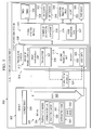
- transducer system 400 is an example of one implementation for transducer system 308 in Figure 3 .
- transducer system 400 includes first transducer unit 402 and second transducer unit 404.
- First transducer unit 402 functions as a transmitter.
- Second transducer unit 404 functions as a sensor.
- first transducer unit 402 has segment 403 and segment 405.
- Second transducer unit 404 has segments 406, 408, and 410. All of these segments are transducers in this depicted example.
- distance 412, d 1 is the distance between the center of first transducer unit 402 and segment 406.
- Distance 414, d 2 is the distance between the center of first transducer unit 402 and segment 408.
- Distance 416, d 3 is the distance between the center of first transducer unit 402 and segment 410.
- First transducer unit 402 is configured to transmit a signal along path 418 through object 420. Segments 406, 408, and 410 are substantially aligned with path 418 in this example. A signal transmitted from first transducer unit 402 and traveling along path 418 reaches the segments for second transducer unit 404 in the order of segment 406, segment 408, and segment 410.
- the signal is detected at segments 406, 408, and 410 having substantially the same velocity.
- the velocities for the signal detected at the different segments may be different.
- the time it takes for a signal transmitted by first transducer unit 402 to reach each of segments 406, 408, and 410 of second transducer unit 404 may be delayed as compared to the time it takes for the signal to reach the segments when inconsistency 422 is not present. This delay may be substantially equal for the time it takes to reach segment 406, the time it takes to reach segment 408, and the time it takes to reach segment 410.
- times 500 are the times at which a signal transmitted by first transducer unit 402 reaches a segment of second transducer unit 404 when inconsistency 422 is present and when inconsistency 422 is not present in object 420 in Figure 4 .
- These times may also be referred to as times of flight.
- time 502, t 1 is the time it takes for the signal to reach segment 406 of second transducer unit 404 when inconsistency 422 is not present.
- Time 504, t 2 is the time it takes for the signal to reach segment 408 of second transducer unit 404 when inconsistency 422 is not present.
- time 506, t 3 is the time it takes for the signal to reach segment 410 of second transducer unit 404 when inconsistency 422 is not present.
- V 1 is the velocity of the signal detected at segment 406
- V 2 is the velocity of the signal detected at segment 408
- V 3 is the velocity of the signal detected at segment 410 .
- times 502, 504, and 506 may be delayed by substantially the same time delay, ⁇ t.
- the signal takes time 508 to reach segment 406, time 510 to reach segment 408, and time 512 to reach segment 410.
- Time 508, time 510, and time 512 are longer time periods than time 502, time 504, and time 506, respectively, by substantially the same amount, ⁇ t.
- the velocities of the signal detected at segments 406, 408, and 410 are different as indicated by the following: d 1 ⁇ ⁇ t + t 1 ⁇ d 2 ⁇ ⁇ t + t 2 ⁇ d 3 ⁇ ⁇ t + t 3 , V 1 ⁇ V 2 ⁇ V 3 .
- Identification of inconsistencies may be performed by comparing velocities. These velocities are identified from signals detected by transducers in which the signals are sent at substantially the same time through an object. The identification of the inconsistencies does not use prior baseline data. This process may be performed to identify inconsistencies even under changing operational and environmental conditions of the object.
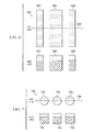
- transducer unit 600 is shown in a top view and a side view.
- Transducer unit 600 is an example of one implementation for second transducer unit 318 in Figure 3 .
- transducer unit 600 comprises transducers 602, 604, and 606. These three transducers are examples of segments 326 in Figure 3 . As can be seen, transducer unit 600 is symmetric along axis 608.
- transducer unit 700 comprises transducer 702, transducer 704, and transducer 706.
- Transducer unit 700 is symmetric about axis 708.
- transducer unit 800 comprises plurality of transducers 802 and transducer 804.
- Plurality of transducers 802 are arranged in the form of a ring around transducer 804 in this illustrative example.
- Transducer unit 800 is symmetric about axis 806 in these examples.
- transducer unit 900 functions as a transmitter, while transducer unit 902 functions as a sensor.
- Transducer unit 900 has ring segment 904 and circular segment 906.
- Transducer unit 902 has circular segment 908, circular segment 909, and circular segment 910.
- path 912 is formed between transducer unit 900 and transducer unit 902. Activation of different segments for the transducer units allows six different Lamb wave signals to be obtained.
- two different Lamb wave signals may be detected by circular segment 909 and circular segment 910 of transducer unit 902 when circular segment 906 of transducer unit 900 is activated.
- two different Lamb wave signals may be detected by circular segment 909 and circular segment 910 of transducer unit 902 when ring segment 904 of transducer unit 900 is activated.
- the modes for signal 914 and signal 916 may have substantially identical arrival times at circular segment 908, respectively, but different amplitudes. Further, the amplitudes of the symmetric (S 0 ) modes and the asymmetric (A 0 ) modes change at different rates as the size of the segment in the transmitting transducer unit that transmits the signal varies.
- the amplitudes of the symmetric modes and the asymmetric modes change depending on which segment is activated to transmit in transducer unit 900. Additionally, the rate at which the amplitude of each mode in the modes for the signal changes, with respect to the size of the particular segment transmitting in transducer unit 900, is not based on the distance between transducer unit 900 and transducer unit 902.
- Signal 914 and signal 916 may be used by, for example, signal analysis module 310 in Figure 3 , to identify a number of modes for use in identifying inconsistencies in an object.
- signal 914 and signal 916 may be excited at ring segment 904 and circular segment 906 for transducer unit 900.
- the amplitudes of the symmetric modes in signal 914 and signal 916 are normalized such that the amplitudes of the symmetric modes are substantially equal.
- the symmetric modes may then be removed by subtracting signal 914, V r1 , from signal 916, V c1 .
- the symmetric modes are subtracted from each other such that only the asymmetric mode remains.
- the signal formed by the subtraction does not preserve the amplitude information.
- This signal does, however, retain arrival time information for the asymmetric mode. In this manner, time information may be identified using the asymmetric mode.
- the asymmetric mode signal or waveform formed contains information for the time of travel between transducer unit 900 and transducer unit 902. In this manner, time information may be identified using the asymmetric mode waveform.
- FIG. 10 an illustration of a flowchart of a process for detecting an inconsistency in an object is depicted in accordance with an advantageous embodiment.
- the process illustrated in Figure 10 may be implemented in health monitoring environment 300 in Figure 3 .
- this process may be implemented within signal analysis module 310 in
- the process begins by sending a signal along a path through an object using a first transducer unit (operation 1000 ).
- This first transducer unit functions as a transmitter.
- the signal sent from the first transducer unit is received at a second transducer unit (operation 1002 ).
- the second transducer unit functions as a sensor.
- the second transducer unit has segments.
- the process then identifies a velocity at each segment in the segments for a number of modes for the signal to form identified velocities (operation 1004 ).
- the number of modes includes one type of mode.
- the mode is an asymmetric mode.
- the determination is made by determining whether a difference between the identified velocities is greater than a threshold. An inconsistency is present along the path when the difference is greater than the threshold.
- the process terminates. Otherwise, if an inconsistency is present, the process generates an alert (operation 1008 ), with the process terminating thereafter.
- each block in the flowchart or block diagrams may represent a module, segment, function, and/or a portion of an operation or step.
- one or more of the blocks may be implemented as program code, in hardware, or a combination of the program code and hardware.
- the hardware may, for example, take the form of integrated circuits that are manufactured or configured to perform one or more operations in the flowcharts or block diagrams.
- the function or functions noted in the block may occur out of the order noted in the figures.
- two blocks shown in succession may be executed substantially concurrently, or the blocks may sometimes be executed in the reverse order, depending upon the functionality involved.
- other blocks may be added in addition to the illustrated blocks in a flowchart or block diagram.
- data processing system 1100 includes communications fabric 1102, which provides communications between processor unit 1104, memory 1106, persistent storage 1108, communications unit 1110, input/output (I/O) unit 1112, and display 1114.
- communications fabric 1102 provides communications between processor unit 1104, memory 1106, persistent storage 1108, communications unit 1110, input/output (I/O) unit 1112, and display 1114.
- Processor unit 1104 serves to execute instructions for software that may be loaded into memory 1106.
- Processor unit 1104 may be a number of processors, a multi-processor core, or some other type of processor, depending on the particular implementation.
- a number, as used herein with reference to an item, means one or more items.
- processor unit 1104 may be implemented using a number of heterogeneous processor systems in which a main processor is present with secondary processors on a single chip.
- processor unit 1104 may be a symmetric multi-processor system containing multiple processors of the same type.
- Memory 1106 and persistent storage 1108 are examples of storage devices 1116.
- a storage device is any piece of hardware that is capable of storing information, such as, for example, without limitation, data, program code in functional form, and/or other suitable information either on a temporary basis and/or a permanent basis.
- Storage devices 1116 may also be referred to as computer readable storage devices in these examples.
- Memory 1106, in these examples, may be, for example, a random access memory or any other suitable volatile or non-volatile storage device.
- Persistent storage 1108 may take various forms, depending on the particular implementation.
- persistent storage 1108 may contain one or more components or devices.
- persistent storage 1108 may be a hard drive, a flash memory, a rewritable optical disk, a rewritable magnetic tape, or some combination of the above.
- the media used by persistent storage 1108 may also be removable.
- a removable hard drive may be used for persistent storage 1108.
- Communications unit 1110 in these examples, provides for communications with other data processing systems or devices.
- communications unit 1110 is a network interface card.
- Communications unit 1110 may provide communications through the use of either or both physical and wireless communications links.
- Input/output unit 1112 allows for input and output of data with other devices that may be connected to data processing system 1100.
- input/output unit 1112 may provide a connection for user input through a keyboard, a mouse, and/or some other suitable input device. Further, input/output unit 1112 may send output to a printer.
- Display 1114 provides a mechanism to display information to a user.
- Instructions for the operating system, applications, and/or programs may be located in storage devices 1116, which are in communication with processor unit 1104 through communications fabric 1102. In these illustrative examples, the instructions are in a functional form on persistent storage 1108. These instructions may be loaded into memory 1106 for execution by processor unit 1104. The processes of the different advantageous embodiments may be performed by processor unit 1104 using computer implemented instructions, which may be located in a memory, such as memory 1106.
- program code computer usable program code
- computer readable program code that may be read and executed by a processor in processor unit 1104.
- the program code in the different embodiments may be embodied on different physical or computer readable storage media, such as memory 1106 or persistent storage 1108.
- Program code 1118 is located in a functional form on computer readable media 1120 that is selectively removable and may be loaded onto or transferred to data processing system 1100 for execution by processor unit 1104.
- Program code 1118 and computer readable media 1120 form computer program product 1122 in these examples.
- computer readable media 1120 may be computer readable storage media 1124 or computer readable signal media 1126.
- Computer readable storage media 1124 may include, for example, an optical or magnetic disk that is inserted or placed into a drive or other device that is part of persistent storage 1108 for transfer onto a storage device, such as a hard drive, that is part of persistent storage 1108.
- Computer readable storage media 1124 may also take the form of a persistent storage, such as a hard drive, a thumb drive, or a flash memory, that is connected to data processing system 1100. In some instances, computer readable storage media 1124 may not be removable from data processing system 1100. In these examples, computer readable storage media 1124 is a physical or tangible storage device used to store program code 1118 rather than a medium that propagates or transmits program code 1118. Computer readable storage media 1124 is also referred to as a computer readable tangible storage device or a computer readable physical storage device. In other words, computer readable storage media 1124 is a media that can be touched by a person.
- program code 1118 may be transferred to data processing system 1100 using computer readable signal media 1126.
- Computer readable signal media 1126 may be, for example, a propagated data signal containing program code 1118.
- Computer readable signal media 1126 may be an electromagnetic signal, an optical signal, and/or any other suitable type of signal. These signals may be transmitted over communications links, such as wireless communications links, optical fiber cable, coaxial cable, a wire, and/or any other suitable type of communications link.
- the communications link and/or the connection may be physical or wireless in the illustrative examples.
- program code 1118 may be downloaded over a network to persistent storage 1108 from another device or data processing system through computer readable signal media 1126 for use within data processing system 1100.
- program code stored in a computer readable storage medium in a server data processing system may be downloaded over a network from the server to data processing system 1100.
- the data processing system providing program code 1118 may be a server computer, a client computer, or some other device capable of storing and transmitting program code 1118.
- the different components illustrated for data processing system 1100 are not meant to provide architectural limitations to the manner in which different embodiments may be implemented.
- the different advantageous embodiments may be implemented in a data processing system including components in addition to or in place of those illustrated for data processing system 1100.
- Other components shown in Figure 11 can be varied from the illustrative examples shown.
- the different advantageous embodiments may be implemented using any hardware device or system capable of running program code.
- the data processing system may include organic components integrated with inorganic components and/or may be comprised entirely of organic components excluding a human being.
- a storage device may be comprised of an organic semiconductor.
- processor unit 1104 may take the form of a hardware unit that has circuits that are manufactured or configured for a particular use. This type of hardware may perform operations without needing program code to be loaded into a memory from a storage device to be configured to perform the operations.
- processor unit 1104 when processor unit 1104 takes the form of a hardware unit, processor unit 1104 may be a circuit system, an application specific integrated circuit (ASIC), a programmable logic device, or some other suitable type of hardware configured to perform a number of operations.
- ASIC application specific integrated circuit
- a programmable logic device the device is configured to perform the number of operations. The device may be reconfigured at a later time or may be permanently configured to perform the number of operations.
- Examples of programmable logic devices include, for example, a programmable logic array, a programmable array logic, a field programmable logic array, a field programmable gate array, and other suitable hardware devices.
- program code 1118 may be omitted because the processes for the different embodiments are implemented in a hardware unit.
- processor unit 1104 may be implemented using a combination of processors found in computers and hardware units.
- Processor unit 1104 may have a number of hardware units and a number of processors that are configured to run program code 1118. With this depicted example, some of the processes may be implemented in the number of hardware units, while other processes may be implemented in the number of processors.
- a bus system may be used to implement communications fabric 1102 and may be comprised of one or more buses, such as a system bus or an input/output bus.
- the bus system may be implemented using any suitable type of architecture that provides for a transfer of data between different components or devices attached to the bus system.
- a communications unit may include a number of one or more devices that are configured to transmit data, receive data, or transmit and receive data.
- a communications unit may be, for example, a modem or a network adapter, two network adapters, or some combination thereof.
- a memory may be, for example, memory 1106, or a cache, such as found in an interface and memory controller hub that may be present in communications fabric 1102.
- the different advantageous embodiments provide a method and apparatus for detecting an inconsistency in an object.
- a signal sent from a first transducer unit is received at a second transducer unit.
- the signal is sent on a path through an object from the first transducer unit to the second transducer unit.
- the second transducer unit has segments.
- a velocity is identified at each segment in the segments for a number of modes for the signal to form identified velocities.
- a determination is made as to whether the inconsistency is present along the path through the object using the identified velocities for the number of modes for the signal.
- inconsistencies are detected without any comparison with previously obtained baseline data. This type of identification of inconsistencies may be performed even in the presence of environmental variations, such as, for example, without limitation, temperature, pressure, and/or other environmental changes.
- velocities are identified from signals sent through an object during a current state for a structure. These velocities are used to determine whether an inconsistency is present in the object. Baseline or other comparisons formed at prior times based on different environmental conditions are not used. As a result, the identification of an inconsistency is not affected by environmental conditions.
- a health monitoring system of an aircraft comprising:
- the health monitoring system wherein the determining step comprises:
Landscapes
- Physics & Mathematics (AREA)
- Biochemistry (AREA)
- General Physics & Mathematics (AREA)
- Life Sciences & Earth Sciences (AREA)
- Chemical & Material Sciences (AREA)
- Analytical Chemistry (AREA)
- Pathology (AREA)
- General Health & Medical Sciences (AREA)
- Health & Medical Sciences (AREA)
- Immunology (AREA)
- Acoustics & Sound (AREA)
- Engineering & Computer Science (AREA)
- Signal Processing (AREA)
- Arrangements For Transmission Of Measured Signals (AREA)
- Geophysics And Detection Of Objects (AREA)
Applications Claiming Priority (1)
| Application Number | Priority Date | Filing Date | Title |
|---|---|---|---|
| US13/083,957 US8544328B2 (en) | 2011-04-11 | 2011-04-11 | Transducer based health monitoring system |
Publications (3)
| Publication Number | Publication Date |
|---|---|
| EP2511701A2 true EP2511701A2 (de) | 2012-10-17 |
| EP2511701A3 EP2511701A3 (de) | 2016-04-20 |
| EP2511701B1 EP2511701B1 (de) | 2020-12-30 |
Family
ID=45977246
Family Applications (1)
| Application Number | Title | Priority Date | Filing Date |
|---|---|---|---|
| EP12163753.2A Active EP2511701B1 (de) | 2011-04-11 | 2012-04-11 | Transducerbasiertes Überwachungssystem der strukurellen Integrität |
Country Status (3)
| Country | Link |
|---|---|
| US (1) | US8544328B2 (de) |
| EP (1) | EP2511701B1 (de) |
| AU (1) | AU2012200897B2 (de) |
Cited By (1)
| Publication number | Priority date | Publication date | Assignee | Title |
|---|---|---|---|---|
| FR3075381A1 (fr) * | 2017-12-19 | 2019-06-21 | Psa Automobiles Sa | Controle de pieces en composite par vibrothermographie detection |
Families Citing this family (10)
| Publication number | Priority date | Publication date | Assignee | Title |
|---|---|---|---|---|
| US8707787B1 (en) | 2011-03-04 | 2014-04-29 | The Boeing Company | Time delay based health monitoring system using a sensor network |
| US9417213B1 (en) * | 2011-07-11 | 2016-08-16 | The Boeing Company | Non-destructive evaluation system for aircraft |
| US9038469B2 (en) | 2011-12-06 | 2015-05-26 | The Boeing Company | Reference free inconsistency detection system |
| US8960005B2 (en) * | 2011-12-12 | 2015-02-24 | Georgia Tech Research Corporation | Frequency-steered acoustic transducer (FSAT) using a spiral array |
| US9470660B2 (en) * | 2014-05-20 | 2016-10-18 | The Boeing Company | Piezoelectric sensor configuration for detecting damage in a structure |
| WO2017175692A1 (ja) * | 2016-04-06 | 2017-10-12 | 株式会社Subaru | 超音波検査システム、超音波検査方法及び航空機構造体 |
| CN108116693B (zh) * | 2016-11-28 | 2022-05-06 | 成都飞机工业(集团)有限责任公司 | 机群与单机状态综合疲劳延寿方法 |
| US11169118B2 (en) * | 2017-06-11 | 2021-11-09 | Broadsens Corp. | Method for extending detection range of a structural health monitoring system |
| CN108152375B (zh) * | 2017-12-19 | 2020-06-02 | 大连理工大学 | 基于超声导波的t型桁条缺陷定位方法 |
| US11519816B2 (en) | 2019-02-18 | 2022-12-06 | The Boeing Company | Composite ply-by-ply damage assessment using correlation factors between finite element models (FEMs) and non-destructive evaluations (NDEs) |
Family Cites Families (14)
| Publication number | Priority date | Publication date | Assignee | Title |
|---|---|---|---|---|
| DE4405504B4 (de) | 1994-02-21 | 2008-10-16 | Siemens Ag | Verfahren und Vorrichtung zum Abbilden eines Objekts mit einem 2-D-Ultraschallarray |
| US5431054A (en) | 1994-04-07 | 1995-07-11 | Reeves; R. Dale | Ultrasonic flaw detection device |
| WO2003106958A2 (en) * | 2002-06-14 | 2003-12-24 | University Of South Carolina | Structural health monitoring system utilizing guided lamb waves embedded ultrasonic structural radar |
| US7325456B2 (en) * | 2003-09-22 | 2008-02-05 | Hyeung-Yun Kim | Interrogation network patches for active monitoring of structural health conditions |
| CN101014938A (zh) * | 2003-09-22 | 2007-08-08 | 金炯胤 | 用于监视结构健康状态的方法 |
| US7921727B2 (en) * | 2004-06-25 | 2011-04-12 | University Of Dayton | Sensing system for monitoring the structural health of composite structures |
| US7333898B2 (en) * | 2006-06-05 | 2008-02-19 | The Boeing Company | Passive structural assessment and monitoring system and associated method |
| US7743659B2 (en) | 2007-05-25 | 2010-06-29 | The Boeing Company | Structural health monitoring (SHM) transducer assembly and system |
| US7917311B2 (en) | 2007-06-04 | 2011-03-29 | Drexel University | Method for structural health monitoring using a smart sensor system |
| US7822573B2 (en) * | 2007-08-17 | 2010-10-26 | The Boeing Company | Method and apparatus for modeling responses for a material to various inputs |
| GB0723526D0 (en) * | 2007-12-03 | 2008-01-09 | Airbus Uk Ltd | Acoustic transducer |
| US7881881B2 (en) | 2008-08-12 | 2011-02-01 | University Of South Carolina | Structural health monitoring apparatus and methodology |
| US8286490B2 (en) | 2008-12-16 | 2012-10-16 | Georgia Tech Research Corporation | Array systems and related methods for structural health monitoring |
| US8286492B2 (en) * | 2009-12-09 | 2012-10-16 | The Boeing Company | Mode decomposition of sound waves using amplitude matching |
-
2011
- 2011-04-11 US US13/083,957 patent/US8544328B2/en active Active
-
2012
- 2012-02-16 AU AU2012200897A patent/AU2012200897B2/en active Active
- 2012-04-11 EP EP12163753.2A patent/EP2511701B1/de active Active
Non-Patent Citations (1)
| Title |
|---|
| None |
Cited By (1)
| Publication number | Priority date | Publication date | Assignee | Title |
|---|---|---|---|---|
| FR3075381A1 (fr) * | 2017-12-19 | 2019-06-21 | Psa Automobiles Sa | Controle de pieces en composite par vibrothermographie detection |
Also Published As
| Publication number | Publication date |
|---|---|
| US20120255359A1 (en) | 2012-10-11 |
| EP2511701A3 (de) | 2016-04-20 |
| EP2511701B1 (de) | 2020-12-30 |
| AU2012200897A1 (en) | 2012-10-25 |
| US8544328B2 (en) | 2013-10-01 |
| AU2012200897B2 (en) | 2015-05-07 |
Similar Documents
| Publication | Publication Date | Title |
|---|---|---|
| US8544328B2 (en) | Transducer based health monitoring system | |
| US8707787B1 (en) | Time delay based health monitoring system using a sensor network | |
| US10124901B2 (en) | Icing condition detection method | |
| US8930042B2 (en) | Mobilized sensor network for structural health monitoring | |
| JP6869042B2 (ja) | 構造物の検査 | |
| EP2602615B1 (de) | Referenzfreie Inkonsistenzdetektion mittels propagierender Wellen in einer Struktur | |
| US10444195B2 (en) | Detection of near surface inconsistencies in structures | |
| US8694269B2 (en) | Reducing the ringing of actuator elements in ultrasound based health monitoring systems | |
| Chang | Structural health monitoring 2013: a roadmap to intelligent structures: proceedings of the ninth international workshop on structural health monitoring, september 10–12, 2013 | |
| US8290719B2 (en) | Mode identification and decomposition for ultrasonic signals | |
| US9038470B1 (en) | Porosity inspection system for composite structures | |
| US9304114B2 (en) | Ultrasonic inspection using incidence angles | |
| JP2015017970A (ja) | 非平面状表面のための超音波検査システム | |
| Pant et al. | Monitoring Tasks in Aerospace | |
| US9417213B1 (en) | Non-destructive evaluation system for aircraft | |
| Wheatley et al. | Comparative vacuum monitoring as an alternate means of compliance | |
| US20100031749A1 (en) | Compensating for temperature effects in a health monitoring system | |
| Dong et al. | Reviews of structural health monitoring technologies in airplane fuselage maintenance perspective |
Legal Events
| Date | Code | Title | Description |
|---|---|---|---|
| PUAI | Public reference made under article 153(3) epc to a published international application that has entered the european phase |
Free format text: ORIGINAL CODE: 0009012 |
|
| 17P | Request for examination filed |
Effective date: 20120411 |
|
| AK | Designated contracting states |
Kind code of ref document: A2 Designated state(s): AL AT BE BG CH CY CZ DE DK EE ES FI FR GB GR HR HU IE IS IT LI LT LU LV MC MK MT NL NO PL PT RO RS SE SI SK SM TR |
|
| AX | Request for extension of the european patent |
Extension state: BA ME |
|
| PUAL | Search report despatched |
Free format text: ORIGINAL CODE: 0009013 |
|
| AK | Designated contracting states |
Kind code of ref document: A3 Designated state(s): AL AT BE BG CH CY CZ DE DK EE ES FI FR GB GR HR HU IE IS IT LI LT LU LV MC MK MT NL NO PL PT RO RS SE SI SK SM TR |
|
| AX | Request for extension of the european patent |
Extension state: BA ME |
|
| RIC1 | Information provided on ipc code assigned before grant |
Ipc: G01N 29/24 20060101ALI20160317BHEP Ipc: G01N 29/07 20060101ALI20160317BHEP Ipc: G01N 29/44 20060101ALI20160317BHEP Ipc: G01N 29/04 20060101AFI20160317BHEP |
|
| STAA | Information on the status of an ep patent application or granted ep patent |
Free format text: STATUS: EXAMINATION IS IN PROGRESS |
|
| 17Q | First examination report despatched |
Effective date: 20170912 |
|
| GRAP | Despatch of communication of intention to grant a patent |
Free format text: ORIGINAL CODE: EPIDOSNIGR1 |
|
| STAA | Information on the status of an ep patent application or granted ep patent |
Free format text: STATUS: GRANT OF PATENT IS INTENDED |
|
| INTG | Intention to grant announced |
Effective date: 20200330 |
|
| GRAJ | Information related to disapproval of communication of intention to grant by the applicant or resumption of examination proceedings by the epo deleted |
Free format text: ORIGINAL CODE: EPIDOSDIGR1 |
|
| STAA | Information on the status of an ep patent application or granted ep patent |
Free format text: STATUS: EXAMINATION IS IN PROGRESS |
|
| INTC | Intention to grant announced (deleted) | ||
| GRAS | Grant fee paid |
Free format text: ORIGINAL CODE: EPIDOSNIGR3 |
|
| STAA | Information on the status of an ep patent application or granted ep patent |
Free format text: STATUS: GRANT OF PATENT IS INTENDED |
|
| GRAP | Despatch of communication of intention to grant a patent |
Free format text: ORIGINAL CODE: EPIDOSNIGR1 |
|
| INTG | Intention to grant announced |
Effective date: 20200922 |
|
| GRAA | (expected) grant |
Free format text: ORIGINAL CODE: 0009210 |
|
| STAA | Information on the status of an ep patent application or granted ep patent |
Free format text: STATUS: THE PATENT HAS BEEN GRANTED |
|
| AK | Designated contracting states |
Kind code of ref document: B1 Designated state(s): AL AT BE BG CH CY CZ DE DK EE ES FI FR GB GR HR HU IE IS IT LI LT LU LV MC MK MT NL NO PL PT RO RS SE SI SK SM TR |
|
| REG | Reference to a national code |
Ref country code: GB Ref legal event code: FG4D |
|
| REG | Reference to a national code |
Ref country code: AT Ref legal event code: REF Ref document number: 1350426 Country of ref document: AT Kind code of ref document: T Effective date: 20210115 |
|
| REG | Reference to a national code |
Ref country code: DE Ref legal event code: R096 Ref document number: 602012073914 Country of ref document: DE |
|
| REG | Reference to a national code |
Ref country code: IE Ref legal event code: FG4D |
|
| PG25 | Lapsed in a contracting state [announced via postgrant information from national office to epo] |
Ref country code: NO Free format text: LAPSE BECAUSE OF FAILURE TO SUBMIT A TRANSLATION OF THE DESCRIPTION OR TO PAY THE FEE WITHIN THE PRESCRIBED TIME-LIMIT Effective date: 20210330 Ref country code: RS Free format text: LAPSE BECAUSE OF FAILURE TO SUBMIT A TRANSLATION OF THE DESCRIPTION OR TO PAY THE FEE WITHIN THE PRESCRIBED TIME-LIMIT Effective date: 20201230 Ref country code: FI Free format text: LAPSE BECAUSE OF FAILURE TO SUBMIT A TRANSLATION OF THE DESCRIPTION OR TO PAY THE FEE WITHIN THE PRESCRIBED TIME-LIMIT Effective date: 20201230 Ref country code: GR Free format text: LAPSE BECAUSE OF FAILURE TO SUBMIT A TRANSLATION OF THE DESCRIPTION OR TO PAY THE FEE WITHIN THE PRESCRIBED TIME-LIMIT Effective date: 20210331 |
|
| REG | Reference to a national code |
Ref country code: AT Ref legal event code: MK05 Ref document number: 1350426 Country of ref document: AT Kind code of ref document: T Effective date: 20201230 |
|
| PG25 | Lapsed in a contracting state [announced via postgrant information from national office to epo] |
Ref country code: BG Free format text: LAPSE BECAUSE OF FAILURE TO SUBMIT A TRANSLATION OF THE DESCRIPTION OR TO PAY THE FEE WITHIN THE PRESCRIBED TIME-LIMIT Effective date: 20210330 Ref country code: SE Free format text: LAPSE BECAUSE OF FAILURE TO SUBMIT A TRANSLATION OF THE DESCRIPTION OR TO PAY THE FEE WITHIN THE PRESCRIBED TIME-LIMIT Effective date: 20201230 Ref country code: LV Free format text: LAPSE BECAUSE OF FAILURE TO SUBMIT A TRANSLATION OF THE DESCRIPTION OR TO PAY THE FEE WITHIN THE PRESCRIBED TIME-LIMIT Effective date: 20201230 |
|
| REG | Reference to a national code |
Ref country code: NL Ref legal event code: MP Effective date: 20201230 |
|
| PG25 | Lapsed in a contracting state [announced via postgrant information from national office to epo] |
Ref country code: HR Free format text: LAPSE BECAUSE OF FAILURE TO SUBMIT A TRANSLATION OF THE DESCRIPTION OR TO PAY THE FEE WITHIN THE PRESCRIBED TIME-LIMIT Effective date: 20201230 |
|
| REG | Reference to a national code |
Ref country code: LT Ref legal event code: MG9D |
|
| PG25 | Lapsed in a contracting state [announced via postgrant information from national office to epo] |
Ref country code: LT Free format text: LAPSE BECAUSE OF FAILURE TO SUBMIT A TRANSLATION OF THE DESCRIPTION OR TO PAY THE FEE WITHIN THE PRESCRIBED TIME-LIMIT Effective date: 20201230 Ref country code: PT Free format text: LAPSE BECAUSE OF FAILURE TO SUBMIT A TRANSLATION OF THE DESCRIPTION OR TO PAY THE FEE WITHIN THE PRESCRIBED TIME-LIMIT Effective date: 20210430 Ref country code: SK Free format text: LAPSE BECAUSE OF FAILURE TO SUBMIT A TRANSLATION OF THE DESCRIPTION OR TO PAY THE FEE WITHIN THE PRESCRIBED TIME-LIMIT Effective date: 20201230 Ref country code: RO Free format text: LAPSE BECAUSE OF FAILURE TO SUBMIT A TRANSLATION OF THE DESCRIPTION OR TO PAY THE FEE WITHIN THE PRESCRIBED TIME-LIMIT Effective date: 20201230 Ref country code: NL Free format text: LAPSE BECAUSE OF FAILURE TO SUBMIT A TRANSLATION OF THE DESCRIPTION OR TO PAY THE FEE WITHIN THE PRESCRIBED TIME-LIMIT Effective date: 20201230 Ref country code: CZ Free format text: LAPSE BECAUSE OF FAILURE TO SUBMIT A TRANSLATION OF THE DESCRIPTION OR TO PAY THE FEE WITHIN THE PRESCRIBED TIME-LIMIT Effective date: 20201230 Ref country code: EE Free format text: LAPSE BECAUSE OF FAILURE TO SUBMIT A TRANSLATION OF THE DESCRIPTION OR TO PAY THE FEE WITHIN THE PRESCRIBED TIME-LIMIT Effective date: 20201230 |
|
| PG25 | Lapsed in a contracting state [announced via postgrant information from national office to epo] |
Ref country code: AT Free format text: LAPSE BECAUSE OF FAILURE TO SUBMIT A TRANSLATION OF THE DESCRIPTION OR TO PAY THE FEE WITHIN THE PRESCRIBED TIME-LIMIT Effective date: 20201230 Ref country code: PL Free format text: LAPSE BECAUSE OF FAILURE TO SUBMIT A TRANSLATION OF THE DESCRIPTION OR TO PAY THE FEE WITHIN THE PRESCRIBED TIME-LIMIT Effective date: 20201230 |
|
| PG25 | Lapsed in a contracting state [announced via postgrant information from national office to epo] |
Ref country code: IS Free format text: LAPSE BECAUSE OF FAILURE TO SUBMIT A TRANSLATION OF THE DESCRIPTION OR TO PAY THE FEE WITHIN THE PRESCRIBED TIME-LIMIT Effective date: 20210430 |
|
| REG | Reference to a national code |
Ref country code: DE Ref legal event code: R097 Ref document number: 602012073914 Country of ref document: DE |
|
| PG25 | Lapsed in a contracting state [announced via postgrant information from national office to epo] |
Ref country code: AL Free format text: LAPSE BECAUSE OF FAILURE TO SUBMIT A TRANSLATION OF THE DESCRIPTION OR TO PAY THE FEE WITHIN THE PRESCRIBED TIME-LIMIT Effective date: 20201230 Ref country code: IT Free format text: LAPSE BECAUSE OF FAILURE TO SUBMIT A TRANSLATION OF THE DESCRIPTION OR TO PAY THE FEE WITHIN THE PRESCRIBED TIME-LIMIT Effective date: 20201230 |
|
| PLBE | No opposition filed within time limit |
Free format text: ORIGINAL CODE: 0009261 |
|
| STAA | Information on the status of an ep patent application or granted ep patent |
Free format text: STATUS: NO OPPOSITION FILED WITHIN TIME LIMIT |
|
| PG25 | Lapsed in a contracting state [announced via postgrant information from national office to epo] |
Ref country code: MC Free format text: LAPSE BECAUSE OF FAILURE TO SUBMIT A TRANSLATION OF THE DESCRIPTION OR TO PAY THE FEE WITHIN THE PRESCRIBED TIME-LIMIT Effective date: 20201230 Ref country code: DK Free format text: LAPSE BECAUSE OF FAILURE TO SUBMIT A TRANSLATION OF THE DESCRIPTION OR TO PAY THE FEE WITHIN THE PRESCRIBED TIME-LIMIT Effective date: 20201230 Ref country code: ES Free format text: LAPSE BECAUSE OF FAILURE TO SUBMIT A TRANSLATION OF THE DESCRIPTION OR TO PAY THE FEE WITHIN THE PRESCRIBED TIME-LIMIT Effective date: 20201230 |
|
| 26N | No opposition filed |
Effective date: 20211001 |
|
| PG25 | Lapsed in a contracting state [announced via postgrant information from national office to epo] |
Ref country code: LU Free format text: LAPSE BECAUSE OF NON-PAYMENT OF DUE FEES Effective date: 20210411 |
|
| REG | Reference to a national code |
Ref country code: BE Ref legal event code: MM Effective date: 20210430 |
|
| PG25 | Lapsed in a contracting state [announced via postgrant information from national office to epo] |
Ref country code: CH Free format text: LAPSE BECAUSE OF NON-PAYMENT OF DUE FEES Effective date: 20210430 Ref country code: LI Free format text: LAPSE BECAUSE OF NON-PAYMENT OF DUE FEES Effective date: 20210430 |
|
| PG25 | Lapsed in a contracting state [announced via postgrant information from national office to epo] |
Ref country code: SI Free format text: LAPSE BECAUSE OF FAILURE TO SUBMIT A TRANSLATION OF THE DESCRIPTION OR TO PAY THE FEE WITHIN THE PRESCRIBED TIME-LIMIT Effective date: 20201230 |
|
| PG25 | Lapsed in a contracting state [announced via postgrant information from national office to epo] |
Ref country code: IE Free format text: LAPSE BECAUSE OF NON-PAYMENT OF DUE FEES Effective date: 20210411 |
|
| PG25 | Lapsed in a contracting state [announced via postgrant information from national office to epo] |
Ref country code: IS Free format text: LAPSE BECAUSE OF FAILURE TO SUBMIT A TRANSLATION OF THE DESCRIPTION OR TO PAY THE FEE WITHIN THE PRESCRIBED TIME-LIMIT Effective date: 20210430 |
|
| PG25 | Lapsed in a contracting state [announced via postgrant information from national office to epo] |
Ref country code: BE Free format text: LAPSE BECAUSE OF NON-PAYMENT OF DUE FEES Effective date: 20210430 |
|
| PG25 | Lapsed in a contracting state [announced via postgrant information from national office to epo] |
Ref country code: HU Free format text: LAPSE BECAUSE OF FAILURE TO SUBMIT A TRANSLATION OF THE DESCRIPTION OR TO PAY THE FEE WITHIN THE PRESCRIBED TIME-LIMIT; INVALID AB INITIO Effective date: 20120411 Ref country code: CY Free format text: LAPSE BECAUSE OF FAILURE TO SUBMIT A TRANSLATION OF THE DESCRIPTION OR TO PAY THE FEE WITHIN THE PRESCRIBED TIME-LIMIT Effective date: 20201230 |
|
| P01 | Opt-out of the competence of the unified patent court (upc) registered |
Effective date: 20230516 |
|
| PG25 | Lapsed in a contracting state [announced via postgrant information from national office to epo] |
Ref country code: SM Free format text: LAPSE BECAUSE OF FAILURE TO SUBMIT A TRANSLATION OF THE DESCRIPTION OR TO PAY THE FEE WITHIN THE PRESCRIBED TIME-LIMIT Effective date: 20201230 |
|
| PGFP | Annual fee paid to national office [announced via postgrant information from national office to epo] |
Ref country code: FR Payment date: 20230425 Year of fee payment: 12 Ref country code: DE Payment date: 20230427 Year of fee payment: 12 |
|
| PGFP | Annual fee paid to national office [announced via postgrant information from national office to epo] |
Ref country code: GB Payment date: 20230427 Year of fee payment: 12 |
|
| PG25 | Lapsed in a contracting state [announced via postgrant information from national office to epo] |
Ref country code: MK Free format text: LAPSE BECAUSE OF FAILURE TO SUBMIT A TRANSLATION OF THE DESCRIPTION OR TO PAY THE FEE WITHIN THE PRESCRIBED TIME-LIMIT Effective date: 20201230 |