EP2511488A1 - Variable valve gear for internal combustion engine - Google Patents
Variable valve gear for internal combustion engine Download PDFInfo
- Publication number
- EP2511488A1 EP2511488A1 EP10835897A EP10835897A EP2511488A1 EP 2511488 A1 EP2511488 A1 EP 2511488A1 EP 10835897 A EP10835897 A EP 10835897A EP 10835897 A EP10835897 A EP 10835897A EP 2511488 A1 EP2511488 A1 EP 2511488A1
- Authority
- EP
- European Patent Office
- Prior art keywords
- cam
- camshaft
- boss
- variable valve
- valve actuation
- Prior art date
- Legal status (The legal status is an assumption and is not a legal conclusion. Google has not performed a legal analysis and makes no representation as to the accuracy of the status listed.)
- Granted
Links
Images


Classifications
-
- F—MECHANICAL ENGINEERING; LIGHTING; HEATING; WEAPONS; BLASTING
- F01—MACHINES OR ENGINES IN GENERAL; ENGINE PLANTS IN GENERAL; STEAM ENGINES
- F01L—CYCLICALLY OPERATING VALVES FOR MACHINES OR ENGINES
- F01L1/00—Valve-gear or valve arrangements, e.g. lift-valve gear
- F01L1/34—Valve-gear or valve arrangements, e.g. lift-valve gear characterised by the provision of means for changing the timing of the valves without changing the duration of opening and without affecting the magnitude of the valve lift
-
- F—MECHANICAL ENGINEERING; LIGHTING; HEATING; WEAPONS; BLASTING
- F01—MACHINES OR ENGINES IN GENERAL; ENGINE PLANTS IN GENERAL; STEAM ENGINES
- F01L—CYCLICALLY OPERATING VALVES FOR MACHINES OR ENGINES
- F01L1/00—Valve-gear or valve arrangements, e.g. lift-valve gear
- F01L1/34—Valve-gear or valve arrangements, e.g. lift-valve gear characterised by the provision of means for changing the timing of the valves without changing the duration of opening and without affecting the magnitude of the valve lift
- F01L1/344—Valve-gear or valve arrangements, e.g. lift-valve gear characterised by the provision of means for changing the timing of the valves without changing the duration of opening and without affecting the magnitude of the valve lift changing the angular relationship between crankshaft and camshaft, e.g. using helicoidal gear
- F01L1/3442—Valve-gear or valve arrangements, e.g. lift-valve gear characterised by the provision of means for changing the timing of the valves without changing the duration of opening and without affecting the magnitude of the valve lift changing the angular relationship between crankshaft and camshaft, e.g. using helicoidal gear using hydraulic chambers with variable volume to transmit the rotating force
-
- F—MECHANICAL ENGINEERING; LIGHTING; HEATING; WEAPONS; BLASTING
- F01—MACHINES OR ENGINES IN GENERAL; ENGINE PLANTS IN GENERAL; STEAM ENGINES
- F01L—CYCLICALLY OPERATING VALVES FOR MACHINES OR ENGINES
- F01L1/00—Valve-gear or valve arrangements, e.g. lift-valve gear
- F01L1/02—Valve drive
- F01L1/04—Valve drive by means of cams, camshafts, cam discs, eccentrics or the like
- F01L1/047—Camshafts
- F01L1/053—Camshafts overhead type
-
- F—MECHANICAL ENGINEERING; LIGHTING; HEATING; WEAPONS; BLASTING
- F01—MACHINES OR ENGINES IN GENERAL; ENGINE PLANTS IN GENERAL; STEAM ENGINES
- F01L—CYCLICALLY OPERATING VALVES FOR MACHINES OR ENGINES
- F01L1/00—Valve-gear or valve arrangements, e.g. lift-valve gear
- F01L1/12—Transmitting gear between valve drive and valve
- F01L1/14—Tappets; Push rods
- F01L1/143—Tappets; Push rods for use with overhead camshafts
-
- F—MECHANICAL ENGINEERING; LIGHTING; HEATING; WEAPONS; BLASTING
- F01—MACHINES OR ENGINES IN GENERAL; ENGINE PLANTS IN GENERAL; STEAM ENGINES
- F01L—CYCLICALLY OPERATING VALVES FOR MACHINES OR ENGINES
- F01L13/00—Modifications of valve-gear to facilitate reversing, braking, starting, changing compression ratio, or other specific operations
-
- F—MECHANICAL ENGINEERING; LIGHTING; HEATING; WEAPONS; BLASTING
- F01—MACHINES OR ENGINES IN GENERAL; ENGINE PLANTS IN GENERAL; STEAM ENGINES
- F01L—CYCLICALLY OPERATING VALVES FOR MACHINES OR ENGINES
- F01L1/00—Valve-gear or valve arrangements, e.g. lift-valve gear
- F01L1/02—Valve drive
- F01L1/04—Valve drive by means of cams, camshafts, cam discs, eccentrics or the like
- F01L1/047—Camshafts
- F01L2001/0471—Assembled camshafts
- F01L2001/0473—Composite camshafts, e.g. with cams or cam sleeve being able to move relative to the inner camshaft or a cam adjusting rod
-
- F—MECHANICAL ENGINEERING; LIGHTING; HEATING; WEAPONS; BLASTING
- F01—MACHINES OR ENGINES IN GENERAL; ENGINE PLANTS IN GENERAL; STEAM ENGINES
- F01L—CYCLICALLY OPERATING VALVES FOR MACHINES OR ENGINES
- F01L1/00—Valve-gear or valve arrangements, e.g. lift-valve gear
- F01L1/02—Valve drive
- F01L1/04—Valve drive by means of cams, camshafts, cam discs, eccentrics or the like
- F01L1/047—Camshafts
- F01L2001/0476—Camshaft bearings
-
- F—MECHANICAL ENGINEERING; LIGHTING; HEATING; WEAPONS; BLASTING
- F01—MACHINES OR ENGINES IN GENERAL; ENGINE PLANTS IN GENERAL; STEAM ENGINES
- F01L—CYCLICALLY OPERATING VALVES FOR MACHINES OR ENGINES
- F01L1/00—Valve-gear or valve arrangements, e.g. lift-valve gear
- F01L1/34—Valve-gear or valve arrangements, e.g. lift-valve gear characterised by the provision of means for changing the timing of the valves without changing the duration of opening and without affecting the magnitude of the valve lift
- F01L1/344—Valve-gear or valve arrangements, e.g. lift-valve gear characterised by the provision of means for changing the timing of the valves without changing the duration of opening and without affecting the magnitude of the valve lift changing the angular relationship between crankshaft and camshaft, e.g. using helicoidal gear
- F01L1/3442—Valve-gear or valve arrangements, e.g. lift-valve gear characterised by the provision of means for changing the timing of the valves without changing the duration of opening and without affecting the magnitude of the valve lift changing the angular relationship between crankshaft and camshaft, e.g. using helicoidal gear using hydraulic chambers with variable volume to transmit the rotating force
- F01L2001/3445—Details relating to the hydraulic means for changing the angular relationship
- F01L2001/34483—Phaser return springs
-
- F—MECHANICAL ENGINEERING; LIGHTING; HEATING; WEAPONS; BLASTING
- F01—MACHINES OR ENGINES IN GENERAL; ENGINE PLANTS IN GENERAL; STEAM ENGINES
- F01L—CYCLICALLY OPERATING VALVES FOR MACHINES OR ENGINES
- F01L2303/00—Manufacturing of components used in valve arrangements
- F01L2303/02—Initial camshaft settings
Definitions
- the present invention relates to a variable valve actuation device for an internal combustion engine, whereby the phase of one of a pair of cams for actuating a pair of intake or exhaust valves is varied relative to the other of the pair of cams by a cam phase change unit.
- a variable valve actuation device is often mounted to the cylinder head of the engine, with a view to improving exhaust gas emission characteristics or pumping loss of the engine.
- variable valve actuation devices are constructed such that a phase difference between multiple valves (a pair of intake valves or exhaust valves) used in many engines is varied to change the period of time over which the multiple valves are opened. For example, out of a pair of cams for actuating a pair of intake or exhaust valves, respectively, the phase of one cam is varied relative to the other cam.
- variable valve actuation devices employ a configuration wherein a shaft member driven by crank output is fitted externally with a fixed first cam and a movable second cam rotatable about the axis of the shaft member such that the first and second cams correspond in position to a pair of intake or exhaust valves, and the phase of the movable second cam is varied relative to the fixed first cam as a reference cam by a cam phase change unit such as a movable vane mechanism, as disclosed in Patent Documents 1 and 2. That is, as the phase of the second cam is varied with reference to the first cam by the cam phase change unit, the period over which the pair of intake or exhaust valves are opened varies greatly.
- the support stability of the second cam fitted around the shaft member depends upon the width dimension of the second cam, and because of a small clearance provided between the second cam and the shaft member to allow the second cam to rotate relative to the shaft member, the second cam is liable to misalignment due to load applied thereto.
- a component part having a hollow boss for example, a cam lobe, is used as the second cam and is fitted at the boss around the shaft member so that the orientation of the second cam may be kept stable.
- a space above a cylinder of the cylinder head where the first and second cams can be arranged is limited.
- the second cam has a one-sided structure such that the boss protrudes not on both sides of the second cam in the width direction of the second cam, but on only one side of the second cam close to the first cam, as disclosed in Patent Documents 1 and 2, in order to maintain stability of the second cam.
- the second cam having the boss is a component part separate from the shaft member, however, dimensional variation can arise because of tolerance of the second cam when the second cam is fitted around the shaft member. Thus, depending on the magnitude of the dimensional variation attributable to tolerance, a situation can possibly occur where the second cam is misaligned exceeding the allowable range. If such misalignment occurs, then local contact takes place. For example, the second cam locally contacts at its edge with the abutting surface of a follower member such as a tappet, or the supporting surface of the second cam or the boss locally contacts at its edge with the outer peripheral surface of the camshaft member. If this occurs, pressure acting upon the surfaces of the contacting component parts excessively increases, causing increased friction or local abrasion of the component parts. If friction increases or local abrasion of the component parts occurs, the variable valve actuation device fails to ensure predetermined engine performance. Also, excessively increased friction or excessive local abrasion may possibly lead to damage to the engine.
- the overall length of the boss is increased to reduce misalignment.
- first and second cams are arranged so as to correspond in position to the pair of intake or exhaust valves mounted on the head of the cylinder, dimensions available between the first and second cams are limited, making it difficult to lengthen the boss to such an extent that stability of the boss is ensured.
- the overall length of the boss is restricted to a length smaller than or equal to the width of the second cam, and it cannot be said that the stability of the boss is sufficiently high. If the overall length of the boss is increased in disregard of the dimensional restrictions, then the lengthened boss influences the first or second cam or with the intake valves (or exhaust valves).
- a camshaft with an assembled structure or what is called an assembled camshaft, is used which includes a shaft member having an inner camshaft rotatably fitted through an outer camshaft, which is a pipe member, as disclosed in Patent Documents 1 and 2, a fixed first cam formed on the outer periphery of the outer camshaft, a movable second cam arranged so as to be rotatable about the axis of the outer camshaft, and a connecting member configured to connect the second cam and the inner camshaft to each other while permitting relative displacement of the outer and inner camshafts.
- a cam phase change unit such as a rotary vane-type cam phase change unit is coupled to an end portion of the shaft member so that the phase of the second cam can be varied relative to the first cam, as a reference cam, in accordance with the relative displacement of the outer and inner camshafts.
- the operation of coupling the cam phase change unit to the assembled camshaft should preferably be simplified and executed by means of as simple equipment as possible.
- the assembled camshaft needs to be held in an orientation when the cam phase change unit is coupled to the assembled camshaft.
- variable valve actuation device for an internal combustion engine, for varying a phase difference between a pair of intake valves provided per cylinder of the engine or a phase difference between a pair of exhaust valves provided per cylinder of the engine.
- the variable valve actuation device comprises: an assembled camshaft including a shaft member which is driven by an output from a crankshaft of the engine and which has a first cam formed thereon for actuating one of the pair of intake or exhaust valves, and a cam lobe having a second cam for actuating the other of the pair of intake or exhaust valves and fitted around the shaft member so as to be displaceable relative to the shaft member in a circumferential direction of the shaft member; and a cam phase change unit configured to vary a phase of the second cam relative to that of the first cam, wherein the cam lobe has a hollow boss fitted around the shaft member, and the boss protrudes from one side of the second cam located opposite the first cam in a width direction of the second cam over a distance greater than the width of the second cam.
- the boss of the cam lobe has a connecting member connected to a control member for transmitting a variable cam phase, and the connecting member is arranged at an end portion of the boss remote from the second cam.
- the connecting member is arranged in a position spaced in an axial direction of the second cam from a member which is configured to actuate the corresponding valve while following movement of the second cam.
- the shaft member is constructed by rotatably fitting an inner camshaft as the control member through an outer camshaft
- the assembled camshaft is configured such that the first cam is formed on an outer periphery of the outer camshaft, that the cam lobe having the second cam is rotatably fitted around the outer periphery of the outer camshaft, and that the connecting member connects the second cam and the inner camshaft to each other while allowing relative displacement of the outer and inner camshafts
- the cam phase change unit is coupled to an end portion of the shaft member and causes the relative displacement of the outer and inner camshafts
- the cam lobe is provided with a hold section permitting the assembled camshaft to be held in an orientation, and when the assembled camshaft is held in the orientation by using the hold section in order to couple the cam phase change unit to the end portion of the shaft member, the connecting member performs a function to prevent rotation of the inner camshaft.
- the hold section is provided on the boss.
- the hold section is constituted by at least one pair of flat surfaces formed on an outer periphery of the boss and permitting the boss to be clamped.
- the connecting member is a pin member inserted diametrically into the shaft member and penetrating through the boss and the outer and inner camshafts to connect the cam lobe and the inner camshaft to each other, diametrically opposite portions of the outer periphery of the boss where a through hole for the pin member opens have flat seating surfaces respectively surrounding open ends of the through hole through which the pin member is inserted, and the hold section is constituted by the seating surfaces of the boss.
- the shaft member is rotatably arranged above the cylinder, the first and second cams are arranged adjacent to each other above the cylinder, and at least part of a shaft section located between the adjacent first and second cams is used as a journal rotatably supported above the cylinder.
- the boss protrudes sideways from the second cam over a distance greater than the width of the second cam without influencing with the first or second cam, whereby misalignment of the boss is satisfactorily suppressed. Since misalignment of the second cam can be suppressed as a result, stability of the second cam fitted on the shaft member increases.
- misalignment of the second cam can be suppressed just by means of the boss protruding sideways from the second cam, without affecting the layout of the first and second cams. Accordingly, misalignment of the second cam can be made to always fall within an allowable range, whereby increased friction or local abrasion of component parts in the variable valve actuation device is suppressed, making it possible to reduce variation in engine performance.
- variable valve actuation device In the variable valve actuation device according to claim 2, the control member for transmitting a variable cam phase and the boss of the cam lobe are connected to each other by the connecting member. Also in this case, misalignment of the second cam can be satisfactorily suppressed.
- the connecting member is arranged outward of the member which actuates the corresponding valve while following the movement of the second cam.
- the cam phase change unit and the inner camshaft can be coupled together by a simple operation using a simple rotation prevention structure for preventing rotation of the inner camshaft, which structure is constituted by the hold section also used for holding the assembled camshaft in the orientation.
- This coupling operation does not require the use of a special holding device, which can be burdensome, or the formation of a holding section on the inner camshaft, thus improving workability during the assembling of the camshaft as well as maintainability on the market.
- the outer camshaft is applied with no external force during the coupling operation, so that deformation or warp of the outer camshaft does not occur.
- the cam lobe having the second cam can be more easily provided with the hold section.
- the assembled camshaft having the hold section with simpler construction can be held by general-purpose equipment.
- the hold section is constituted by a pair of seating surfaces of the boss forming part of the structure for connecting the cam lobe and the inner camshaft to each other by the pin member.
- the second cam is supported in its close vicinity by making use of the space between the first and second cams. It is therefore possible to suppress misalignment of the second cam attributable to warp of the shaft member, whereby sufficient stability of the second cam is secured by making full use of the limited space above the cylinder.
- FIGS. 1 through 9 One embodiment of the present invention will be hereinafter described with reference to FIGS. 1 through 9 .
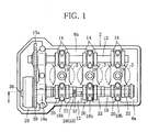
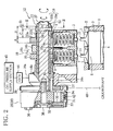
- FIG. 1 is a plan view of an internal combustion engine, for example, a reciprocating engine (hereinafter merely referred to as engine) with three cylinders (multiple cylinders), and FIG. 2 is a sectional view taken along line I-I in FIG. 1 .
- reference numeral 1 denotes a cylinder block of the engine
- 2 denotes a cylinder head mounted to the head of the cylinder block 1.
- FIGS. 1 and 2 three cylinders 3 (in the figures, only partly shown) are formed in the cylinder block 1 and arranged along the longitudinal direction of the engine.
- a piston 4 (illustrated in FIG. 2 only) connected to a crankshaft (not shown) by a connecting rod (not shown) is received in each cylinder 3 for reciprocating motion.
- Combustion chambers 5 associated with the respective cylinders 3 are formed so as to face the lower surface of the cylinder head 2.
- a pair of intake ports 7 (two in number) for admitting air and a pair of exhaust ports (not shown) for discharging air open into each of the combustion chambers 5.
- the intake ports 7 are fitted with a pair of intake valves 10 (two in number but not limited to two), respectively, each having a tappet 9 (follower member) attached to an end of its stem.
- Each tappet 9 has a valve abutting surface 9a facing upward and located at the top of the cylinder head 2.
- the exhaust ports (not shown) are also fitted with a pair of exhaust valves (two in number but not limited to two, not shown), respectively, each having a tappet, like the intake valve.
- the intake ports 7 are opened and closed by the respective intake valves 10, and the exhaust ports (not shown) are opened and closed by the respective exhaust valves (not shown).
- each combustion chamber 5 is provided with a spark plug, although not illustrated.
- an intake-side valve actuation device 6a and an exhaust-side valve actuation device 6b are arranged on the right and left sides of the upper part of the cylinder head 2 so that a predetermined combustion cycle (four-stroke cycle including an intake stroke, a compression stroke, an expansion stroke and an exhaust cycle) may repeatedly take place in each cylinder 3.
- a predetermined combustion cycle four-stroke cycle including an intake stroke, a compression stroke, an expansion stroke and an exhaust cycle
- the exhaust-side valve actuation device 6b uses an ordinary camshaft 13 having pairs of exhaust cams 14 integrally formed thereon (e.g., by cutting).
- the camshaft 13 is rotatably mounted so as to extend in a direction in which the cylinders 3 are lined up, and the cam face of each exhaust cam 14 is disposed in contact with the proximal end of the corresponding exhaust valve (not shown). Consequently, the movement of each exhaust cam 14 is transmitted to the corresponding exhaust valve (not shown).
- the intake-side valve actuation device 6a uses a camshaft 15 (shaft member) constituted by separate members combined together as shown in FIGS. 2 to 4 , unlike the exhaust-side camshaft 13.
- the camshaft 15 forms part of a split-type variable valve actuation device 12.
- FIGS. 2 to 4 illustrate a variable structure of the variable valve actuation device 12 associated with one cylinder.
- the camshaft 15 has one end portion rotatably supported by a bearing 18a arranged at a corresponding end portion of the cylinder head 2, and has an intermediate portion rotatably supported by bearings 18b arranged at respective appropriate portions of the cylinder head 2.
- the bearings 18a and 18b are each constituted by a bearing support 16a and a bearing cap 16b combined with the bearing support 16a, both provided at the cylinder head side.
- the camshaft 15 is provided with intake cams 19 such that each pair of intake cams 19 (two in number but not limited to two) is associated with a corresponding pair of intake valves 10 of one cylinder 3.
- Each pair of intake cams 19 comprises the combination of a fixed cam 20 (first cam) determining a reference phase and a cam lobe 22 serving as a movable cam.
- a double shaft is used for the camshaft 15.
- a cam phase change unit 25 is attached to one end of the double shaft. Inner and outer shafts of the double shaft are rotationally displaced relative to each other by the cam phase change unit 25, in order to vary the phase of the cam lobe 22 relative to that of the fixed cam 20 (assembled camshaft).
- the camshaft 15 is constituted, for example, by an outer camshaft 15a, which is a hollow pipe member, and an inner camshaft 15b (control member), which is a solid shaft member rotatably fitted through the outer camshaft 15a and serves as a control member, as illustrated in FIGS. 2 to 4 .
- a clearance is provided between the outer and inner camshafts 15a and 15b to permit relative displacement of the camshafts 15a and 15b.
- one end portion of the outer camshaft 15a is rotatably supported by the bearing 18a at the one end of the cylinder head 2 through the agency of a bracket 37 attached to the corresponding end of the outer camshaft 15a.
- the outer camshaft 15a is rotatably supported at its intermediate portion by the bearings 18b each situated between the corresponding pair of tappets 9, 9.
- the paired intake cams 19 are provided on the outer camshaft 15a such that each pair (two in number) is associated with the corresponding cylinder.
- the fixed cam 20 associated with each of the cylinders 3 is constituted by a plate cam, as illustrated in FIGS. 2 to 4 .
- the plate cam is attached, for example, fixed by press fitting, to the outer periphery of the outer camshaft 15a.
- the fixed cam 20 is located immediately above the corresponding left-hand tappet 9.
- a cam nose formed on the outer periphery of the fixed cam 20 is disposed in contact with the valve abutting surface 9a of the left-hand tappet 9, so that radial cam displacement of the cam nose is transmitted to the left-hand intake valve 10 to actuate same.
- the cam lobe 22 associated with each of the cylinders 3 has a cam nose 22a (second cam) constituted by a plate cam.
- the cam nose 22a has a hollow boss, for example, a cylindrical boss 22b combined therewith, and the cam nose 22a and the boss 22b constitute the whole cam lobe 22.
- the cam nose 22a is fitted, together with the boss 22b, around the outer camshaft 15a so as to be displaceable in the circumferential direction, and is arranged in a position adjacent to the fixed cam 20 associated therewith, that is, immediately above the right-hand tappet 9.
- FIG. 5 is a sectional view taken along line II-II in FIG. 2 .
- the boss 22b has an outer diameter D1 smaller than a base circle D2 of the cam nose 22a (D1 ⁇ D2) so that the boss 22b may not come into contact with the tappet 9. The boss 22b will be described in detail later.
- each boss 22b and that portion of the inner camshaft 15b which is located radially inward of the boss 22b are coupled together by a pin member penetrating through the boss 22b and the inner camshaft 15b, for example, by a press fitting pin 27 (connecting member).
- Reference sign 27a ( FIG. 4 ) denotes a press fitting hole formed through the inner camshaft 15b and the peripheral wall of the boss 22b to allow the press fitting pin 27 to be press-fitted.
- each boss 22b has flat seats formed on portions (diametrically opposite portions) of the outer peripheral surface thereof where the through hole 27a for the press fitting pin 27 opens, that is, a pair of flat seating surfaces 29 surrounding the respective opposite open ends of the press fitting hole 27a, as illustrated in FIGS. 3 and 4 .
- a hydraulic rotary vane mechanism 26 is used, for example, which is attached to one end of the camshaft 15, as shown in FIGS. 2 to 4 , to drive the outer and inner camshafts 15a and 15b relative to each other.
- the rotary vane mechanism 26 includes, for example, a cylindrical housing 31 having a plurality of retardation chambers 30 formed therein and arranged in a circumferential direction thereof, and a vane section 34 rotatably received in the housing 31 and having a plurality of vanes 33 radially protruding from the outer periphery of a shaft portion 32, each retardation chamber 30 being partitioned by the corresponding vanes 33.
- a timing sprocket 39 is formed on the outer periphery of the housing 31. The sprocket 39 is connected to the crankshaft (not shown) by a timing chain 40.
- the housing 31 is coupled by means of fixing bolts 36 to the bracket 37 attached to the one end of the outer camshaft 15a, and the shaft portion 32 of the vane section 34 is coupled by means of a fixing bolt 38 to the one end of the inner camshaft 15b.
- the vanes 33 revolve within the retardation chambers 30, the inner camshaft 15b rotates relative to the outer camshaft 15a.
- the cam phase of the cam nose 22a is made to coincide with that of the fixed cam 20 as the reference cam by the urging force of a return spring member 42 (shown in FIG. 2 only) connecting the housing 31 and the vane section 34 to each other.
- the retardation chambers 30 are individually connected to an oil control valve 44 (hereinafter referred to as OCV 44) and an oil pressure supply section 44 (constituted, e.g., by an oil pump for supplying oil) via an oil passage 43 (only partly shown in FIG. 2 ) formed in various component parts such as the housing 31, the bracket 37, and the bearing 18a.
- split variable control can be performed by using the cam nose 22a, as illustrated in FIG. 6 .
- the shaft output of the crankshaft is transmitted to the outer camshaft 15a through the timing chain 40, the timing sprocket 39, the housing 31 and the bracket 37 to rotate the fixed cam 20, so that the left-hand intake valve 10a is opened and closed by means of the tappet 9.
- the cam phase of the cam nose 22a is caused to coincide with that of the fixed cam 20 by the urging force of the return spring member 42, as indicated by state A in FIG. 6 .
- the right-hand intake valve 10b is opened and closed in phase with the fixed cam 20.
- the vanes 33 are displaced within the retardation chambers 30 in the retarding direction from their initial position in accordance with the oil pressure applied thereto.
- the vanes 33 are moved to an intermediate position within the retardation chambers 30, for example, by oil pressure output control, the inner camshaft 15b is displaced in the retarding direction up to an intermediate position. This displacement is transmitted to the cam lobe 22 through the press fitting pin 27, displacing the cam lobe 22 in the retarding direction. Consequently, the open/close timing of the right-hand intake valve 10b alone varies while the reference open/close timing of the left-hand intake valve 10a remains unchanged, as indicated by state B in FIG. 6 .
- the reference open/close timing of the left-hand intake valve 10a remains unchanged, but the right-hand intake valve 10b is opened and closed at the times most retarded from the opening and closing times of the left-hand intake valve 10a with the open/close timing thereof shifted from that of the left-hand intake valve 10a, as indicated by state C in FIG. 6 .
- the overall valve open period of the left- and right-hand intake valves 10a and 10b varies within a range from the shortest valve open period a to the longest valve open period ⁇ , as shown in FIG. 6 .
- the boss 22b can be configured to protrude from the cam nose 22a not toward the fixed cam 20, but to the side opposite the fixed cam 20, and thus can be lengthened (extended) without influencing with the fixed cam 20 and the cam nose 22a laid out in a predetermined manner.
- the overall length B of the boss 22b is set to such a dimension that the boss 22b protrudes over a distance longer than the cam width A of the cam nose 22a that receives load, whereby misalignment (tilting) of the boss 22b is suppressed, enhancing the stability of the cam lobe 22 fitted on the outer camshaft 15a.
- the boss 22b is unstable and may possibly be tilted beyond an allowable range ( ⁇ 1 in FIG. 7 ) due to tolerances such as component tolerance and assembling tolerance, with the result that the cam nose 22a locally contacts at its edge with the abutting surface 9a of the tappet 9 due to misalignment attributable to the tilting of the cam lobe 22.
- the misalignment of the cam nose 22a can be satisfactorily suppressed by merely arranging the press fitting pin 27 in such a manner that the press fitting pin 27 is located at the end portion of the boss 22b remote from the cam nose 22a, more specifically, in a position close to the end portion of the boss 22b opposite the cam nose 22a as indicated by C > D in FIGS. 2 to 4 , and also that the press fitting pin 27 is located outward of the tappet 9 (driven member), which actuates the valve.
- the press fitting pin 27 itself may actuate the tappet 9 with timing different from that determined by the cam nose 22a or may drop off into the space between the tappet 9 and the outer camshaft, possibly leading to serious failure such as interference between the valve and the piston.
- the press fitting pin 27 so as to be located outward of the tappet 9 (driven member) for actuating the valve, it is possible to significantly reduce the possibility of the press fitting pin 27 causing serious failure.
- the valve actuating member is constituted by a rocker arm having a roller incorporated therein, instead of the tappet 9.
- the cam nose 22a is supported by the bearing 18b located in its close vicinity. Accordingly, misalignment of the cam nose 22a attributable to warp of the outer camshaft 15a can also be suppressed. Moreover, since the outer camshaft 15a is supported by making use of the space above the cylinder 3, a space can be secured on one side of the cam lobe 22, allowing the boss 22b to protrude into that space. It is therefore possible to ensure sufficient stability of the cam nose 22a while making efficient use of the limited space above the cylinder 3.
- the camshaft 15 of the variable valve actuation device 12 is configured such that the inner camshaft 15b is rotatably fitted through the outer camshaft 15a. Because of this specific configuration, the inner camshaft 15b is subject to rotational displacement. With the camshaft 15, therefore, difficulty arises in the operation of coupling the cam phase change unit 25 to the end of the inner camshaft 15b.
- each cam lobe 22 is provided with a hold section 52 which can be held by general-purpose equipment to keep the whole camshaft 15 in an orientation when the cam phase change unit 25 is coupled to the end of the camshaft 15, which is a double shaft.
- the hold section 52 per se serves to prevent rotation of the inner camshaft 15b.
- the hold section 52 is provided on the boss 22b that is formed to suppress misalignment of the cam nose 22a.
- the hold section 52 is constituted by a pair of parallel flat surfaces 53 (two parallel flats) formed on diametrically opposite portions of the outer periphery of the boss 22b.
- the boss 22b with the pair of flat surfaces 53 can be clamped by a clamping device, which is general-purpose equipment.
- the camshaft 15 as a whole can be held in an orientation. It is therefore possible to improve workability at the time of assembling as well as maintainability on the market.
- the hold section 52 is formed at a distance from the cam nose 22a, it is also possible to significantly reduce the possibility of the cam nose or tappets being accidentally damaged during the maintenance on the market.
- the press fitting pin 27 is inserted up to a predetermined position by using general-purpose equipment.
- a pair of seating surfaces 29 surrounding the open ends (in communication with the press fitting hole 27a) through which the press fitting pin 27 is inserted are formed on diametrically opposite portions of the outer periphery of the boss 22b where the press fitting hole 27a for the press fitting pin 27 opens.
- the flat surfaces 53 need not be separately formed and the seating surfaces 29 may be directly used as the flat surfaces 53 (hold section 52).
- the press fitting pin 27 serves to prevent deformation of the clamped boss 22b.
- This embodiment exemplifies the case where the flat surfaces 53 are constituted by a pair of seating surfaces 29.
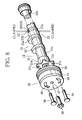
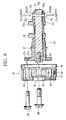
- the use of the hold section 52 makes it easy to couple the end portion of the camshaft 15 and the output section of the cam phase change unit 25 to each other, as shown in FIGS. 8 and 9 .
- each cam lobe 22 fitted around the outer periphery of the outer camshaft 15a is clamped at its paired flat surfaces 53, as illustrated in FIGS. 8 and 9 , by general-purpose equipment, not shown, and the camshaft 15 as a whole is held in an orientation suited for the coupling operation.
- the cam phase change unit 25 is positioned close to that end portion of the camshaft 15 which is provided with a cam piece 37, and the bolt hole 47 formed axially through the housing 31 of the cam phase change unit 25 is aligned with a threaded hole 15c formed axially in the end portion of the inner camshaft 15b. Then, the multiple bolt holes 48 formed through the outer peripheral portion of the housing 31 are aligned with respective threaded holes 37c formed through arms 37a protruding radially outward from the cam piece 37. Subsequently, the fixing bolts 36 are screwed into the respective bolt holes 48, whereupon the cam phase change unit 25 is coupled to the end of the outer camshaft 15a. Further, the fixing bolt 38 is inserted through the bolt hole 47 in the center of the housing 31 and screwed into the threaded hole 15c of the inner camshaft 15b.
- the press fitting pin 27 Since, at this time, the press fitting pin 27 is connected to the boss 22b and also the cam lobe 22 is held at the flat surfaces 53, movement of the press fitting pin 27 is restricted. Also, the press fitting pin 27 is connected to the inner camshaft 15b rotatably fitted through the outer camshaft 15a, and therefore, rotation of the inner camshaft 15b is prevented by the press fitting pin 27. Since rotation of the inner camshaft 15b is prevented, the fixing bolt 38 can be screwed into the threaded hole 15c of the inner camshaft 15b, as illustrated in FIG. 3 , whereby the vane section 34 of the cam phase change unit 25 is coupled to the end portion of the inner camshaft 15b.
- the hold section 52 is used not only to hold the camshaft 15 in the orientation but to prevent rotation of the inner camshaft 15b, and therefore, the inner camshaft 15b and the cam phase change unit 25 can be coupled together without the need to use a special holding device. Since no separate operation is required to prevent rotation of the inner camshaft 15b, the coupling operation can be performed with ease. During the coupling operation, moreover, the outer camshaft 15a is applied with no external force. Accordingly, deformation or warp of the outer camshaft 15a does not occur, making it possible to suppress increased friction between the outer camshaft 15a and the journal bearing 18b of the cylinder head 2 and between the cam (cam nose 22a) and the tappet. As a result, abnormal abrasion of the individual component parts due to increased friction, damage to the component parts attributable to abnormal abrasion and thus damage to the engine can be prevented.
- the hold section 52 has a simple construction because, in the case of the cam lobe 22 provided with the boss 22b, the hold section 52 can be formed on the boss 22b. Further, where the hold section 52 is constituted by a pair of flat surfaces 53 formed on the outer periphery of the boss 22b, the camshaft can be easily held by general-purpose equipment. Each of the multiple cam lobes 22 of the multi-cylinder engine may be provided with the hold section 52. In this case, the hold section 52 corresponding to any one of the cylinders may be held by general-purpose equipment in order to prevent rotation of the inner camshaft, whereby maintenance and assembling are facilitated.
- the seating surfaces 29 per se can be used as the flat surfaces 53, providing the advantage that the hold section 52 can be constituted by using existing elements without the need for any additional machining or the like.
- the cam nose 22a may be formed by using, as a reference position, the pair of flat surfaces 53 formed on the outer periphery of the boss 22b of the cam lobe 22 or the press fitting hole 27a for the press fitting pin 27. In this case, the positional accuracy of the cam nose 22a in the direction of assembling can be checked and confirmed by means of the flat surfaces 53 or the press fitting hole 27a when the cams are assembled, enhancing the productivity of the camshaft 15.
- variable valve actuation device for an internal combustion engine has been described above, it is to be noted that the present invention is not limited to the foregoing embodiment.
- the present invention is applied to the variable valve actuation device configured to vary the phases of a pair of intake cams for actuating a pair of intake valves, respectively.
- the device to which the present invention is applicable is not limited to such a variable valve actuation device, and the present invention may be applied to a variable valve actuation device which is configured to vary the phases of a pair of exhaust cams for actuating a pair of exhaust valves, respectively.
- the intake valves are replaced by the exhaust valves, and the intake cams by the exhaust cams.
- variable valve actuation device may be configured such that the variable phase change mechanism is used in combination with a conventional variable phase change mechanism (mechanism capable of varying the phases of both valves at the same time).
- the timing sprocket may be attached to either of the two variable phase change mechanisms.
- a pair of flat surfaces is exemplified as the hold section.
- the hold section to be used is, however, not limited to the one explained with reference to the embodiment and may be constituted by two or three pairs of flat surfaces or some other suitable structural means insofar as the hold section permits the cam lobe to be held in position and can prevent rotation of the inner camshaft.
Landscapes
- Engineering & Computer Science (AREA)
- Mechanical Engineering (AREA)
- General Engineering & Computer Science (AREA)
- Valve Device For Special Equipments (AREA)
- Valve-Gear Or Valve Arrangements (AREA)
Abstract
Description
- The present invention relates to a variable valve actuation device for an internal combustion engine, whereby the phase of one of a pair of cams for actuating a pair of intake or exhaust valves is varied relative to the other of the pair of cams by a cam phase change unit.
- In reciprocating engines (internal combustion engines) mounted on automobiles, a variable valve actuation device is often mounted to the cylinder head of the engine, with a view to improving exhaust gas emission characteristics or pumping loss of the engine.
- Such variable valve actuation devices are constructed such that a phase difference between multiple valves (a pair of intake valves or exhaust valves) used in many engines is varied to change the period of time over which the multiple valves are opened. For example, out of a pair of cams for actuating a pair of intake or exhaust valves, respectively, the phase of one cam is varied relative to the other cam.
- Many of variable valve actuation devices employ a configuration wherein a shaft member driven by crank output is fitted externally with a fixed first cam and a movable second cam rotatable about the axis of the shaft member such that the first and second cams correspond in position to a pair of intake or exhaust valves, and the phase of the movable second cam is varied relative to the fixed first cam as a reference cam by a cam phase change unit such as a movable vane mechanism, as disclosed in
Patent Documents - In order to maintain stability of the second cam, a component part having a hollow boss, for example, a cam lobe, is used as the second cam and is fitted at the boss around the shaft member so that the orientation of the second cam may be kept stable.
- However, a space above a cylinder of the cylinder head where the first and second cams can be arranged is limited.
- Accordingly, in the variable valve actuation devices for varying the phase of one cam relative to the other, the second cam has a one-sided structure such that the boss protrudes not on both sides of the second cam in the width direction of the second cam, but on only one side of the second cam close to the first cam, as disclosed in
Patent Documents -
- Patent Document 1: Japanese Laid-open Patent Publication No.
2009-144521 - Patent Document 2: Japanese Laid-open Patent Publication No.
2009-144522 - However, even the boss configured in the aforementioned manner is liable to misalignment due to load applied thereto from one side thereof, and tilting of the second cam to one side in the width direction thereof is unavoidable. Such misalignment poses no particular problem if the amount of misalignment is within a predetermined allowable range.
- Since the second cam having the boss is a component part separate from the shaft member, however, dimensional variation can arise because of tolerance of the second cam when the second cam is fitted around the shaft member. Thus, depending on the magnitude of the dimensional variation attributable to tolerance, a situation can possibly occur where the second cam is misaligned exceeding the allowable range. If such misalignment occurs, then local contact takes place. For example, the second cam locally contacts at its edge with the abutting surface of a follower member such as a tappet, or the supporting surface of the second cam or the boss locally contacts at its edge with the outer peripheral surface of the camshaft member. If this occurs, pressure acting upon the surfaces of the contacting component parts excessively increases, causing increased friction or local abrasion of the component parts. If friction increases or local abrasion of the component parts occurs, the variable valve actuation device fails to ensure predetermined engine performance. Also, excessively increased friction or excessive local abrasion may possibly lead to damage to the engine.
- It is conceivable that the overall length of the boss is increased to reduce misalignment. However, since the first and second cams are arranged so as to correspond in position to the pair of intake or exhaust valves mounted on the head of the cylinder, dimensions available between the first and second cams are limited, making it difficult to lengthen the boss to such an extent that stability of the boss is ensured. In
Patent Documents - Meanwhile, as the camshaft, a camshaft with an assembled structure, or what is called an assembled camshaft, is used which includes a shaft member having an inner camshaft rotatably fitted through an outer camshaft, which is a pipe member, as disclosed in
Patent Documents - In constructing this type of variable valve actuation device, the operation of coupling the cam phase change unit to the assembled camshaft should preferably be simplified and executed by means of as simple equipment as possible. To that end, the assembled camshaft needs to be held in an orientation when the cam phase change unit is coupled to the assembled camshaft.
- It is an object of the present invention to provide a variable valve actuation device for an internal combustion engine in which misalignment of a second cam can be satisfactorily suppressed by a boss protruding sideways from the second cam, without influence with a first or second cam, and which can be easily assembled by a simple operation using simple equipment.
- To achieve the above object, there is provided in accordance with claim 1 a variable valve actuation device for an internal combustion engine, for varying a phase difference between a pair of intake valves provided per cylinder of the engine or a phase difference between a pair of exhaust valves provided per cylinder of the engine. The variable valve actuation device comprises: an assembled camshaft including a shaft member which is driven by an output from a crankshaft of the engine and which has a first cam formed thereon for actuating one of the pair of intake or exhaust valves, and a cam lobe having a second cam for actuating the other of the pair of intake or exhaust valves and fitted around the shaft member so as to be displaceable relative to the shaft member in a circumferential direction of the shaft member; and a cam phase change unit configured to vary a phase of the second cam relative to that of the first cam, wherein the cam lobe has a hollow boss fitted around the shaft member, and the boss protrudes from one side of the second cam located opposite the first cam in a width direction of the second cam over a distance greater than the width of the second cam.
- According to
claim 2, in the variable valve actuation device ofclaim 1, the boss of the cam lobe has a connecting member connected to a control member for transmitting a variable cam phase, and the connecting member is arranged at an end portion of the boss remote from the second cam. - According to
claim 3, in the variable valve actuation device ofclaim 2, the connecting member is arranged in a position spaced in an axial direction of the second cam from a member which is configured to actuate the corresponding valve while following movement of the second cam. - According to
claim 4, in the variable valve actuation device ofclaim - According to
claim 5, in the variable valve actuation device ofclaim 4, the hold section is provided on the boss. - According to claim 6, in the variable valve actuation device of
claim 5, the hold section is constituted by at least one pair of flat surfaces formed on an outer periphery of the boss and permitting the boss to be clamped. - According to claim 7, in the variable valve actuation device of
claim 5, the connecting member is a pin member inserted diametrically into the shaft member and penetrating through the boss and the outer and inner camshafts to connect the cam lobe and the inner camshaft to each other, diametrically opposite portions of the outer periphery of the boss where a through hole for the pin member opens have flat seating surfaces respectively surrounding open ends of the through hole through which the pin member is inserted, and the hold section is constituted by the seating surfaces of the boss. - According to claim 8, in the variable valve actuation device of any one of
claims 1 to 7, the shaft member is rotatably arranged above the cylinder, the first and second cams are arranged adjacent to each other above the cylinder, and at least part of a shaft section located between the adjacent first and second cams is used as a journal rotatably supported above the cylinder. - According to
claim 1, the boss protrudes sideways from the second cam over a distance greater than the width of the second cam without influencing with the first or second cam, whereby misalignment of the boss is satisfactorily suppressed. Since misalignment of the second cam can be suppressed as a result, stability of the second cam fitted on the shaft member increases. - That is, excessive misalignment of the second cam can be suppressed just by means of the boss protruding sideways from the second cam, without affecting the layout of the first and second cams. Accordingly, misalignment of the second cam can be made to always fall within an allowable range, whereby increased friction or local abrasion of component parts in the variable valve actuation device is suppressed, making it possible to reduce variation in engine performance.
- In the variable valve actuation device according to
claim 2, the control member for transmitting a variable cam phase and the boss of the cam lobe are connected to each other by the connecting member. Also in this case, misalignment of the second cam can be satisfactorily suppressed. - According to
claim 3, the connecting member is arranged outward of the member which actuates the corresponding valve while following the movement of the second cam. Thus, in the event that the connecting member projects to one side or drops off, for example, it is possible to avoid a situation where the connecting member engages with the valve actuation member, whereby serious damage to the engine can be prevented. - According to
claim 4, when the assembled camshaft is held in the orientation by using the hold section provided on the cam lobe with the second cam in order to couple the cam phase change unit to the assembled camshaft, movement of the connecting member is restricted because the connecting member is connected to the second cam, whereby rotation of the inner camshaft connected to the second cam is prevented. - Thus, the cam phase change unit and the inner camshaft can be coupled together by a simple operation using a simple rotation prevention structure for preventing rotation of the inner camshaft, which structure is constituted by the hold section also used for holding the assembled camshaft in the orientation. This coupling operation does not require the use of a special holding device, which can be burdensome, or the formation of a holding section on the inner camshaft, thus improving workability during the assembling of the camshaft as well as maintainability on the market. Further, the outer camshaft is applied with no external force during the coupling operation, so that deformation or warp of the outer camshaft does not occur.
- According to
claim 5, the cam lobe having the second cam can be more easily provided with the hold section. - According to claim 6, the assembled camshaft having the hold section with simpler construction can be held by general-purpose equipment.
- According to claim 7, the hold section is constituted by a pair of seating surfaces of the boss forming part of the structure for connecting the cam lobe and the inner camshaft to each other by the pin member. Thus, existing elements can be directly used as the hold section, making the hold section simpler in construction.
- According to claim 8, the second cam is supported in its close vicinity by making use of the space between the first and second cams. It is therefore possible to suppress misalignment of the second cam attributable to warp of the shaft member, whereby sufficient stability of the second cam is secured by making full use of the limited space above the cylinder.
-
-
FIG. 1 is a plan view illustrating a variable valve actuation device according to the present invention, along with a cylinder head of an internal combustion engine to which the variable valve actuation device is mounted. -
FIG. 2 is a sectional view of the variable valve actuation device, taken along line I-I inFIG. 1 . -
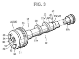
FIG. 3 is a perspective view illustrating a configuration of the variable valve actuation device. -
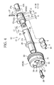
FIG. 4 is an exploded perspective view of the variable valve actuation device. -
FIG. 5 is a sectional view taken along line II-II inFIG. 2 . -
FIG. 6 is a diagram illustrating variable characteristics of the variable valve actuation device. -
FIG. 7 is a sectional view illustrating misalignment of the variable valve actuation device, in comparison with misalignment of a conventional device. -
FIG. 8 is a perspective view illustrating the manner of how a camshaft and a cam phase change unit are coupled together. -
FIG. 9 is a sectional view illustrating the manner of how the camshaft and the cam phase change unit are coupled together. - One embodiment of the present invention will be hereinafter described with reference to
FIGS. 1 through 9 . -
FIG. 1 is a plan view of an internal combustion engine, for example, a reciprocating engine (hereinafter merely referred to as engine) with three cylinders (multiple cylinders), andFIG. 2 is a sectional view taken along line I-I inFIG. 1 . In the figures,reference numeral 1 denotes a cylinder block of the engine, and 2 denotes a cylinder head mounted to the head of thecylinder block 1. - As illustrated in
FIGS. 1 and2 , three cylinders 3 (in the figures, only partly shown) are formed in thecylinder block 1 and arranged along the longitudinal direction of the engine. A piston 4 (illustrated inFIG. 2 only) connected to a crankshaft (not shown) by a connecting rod (not shown) is received in eachcylinder 3 for reciprocating motion. -
Combustion chambers 5 associated with therespective cylinders 3 are formed so as to face the lower surface of thecylinder head 2. A pair of intake ports 7 (two in number) for admitting air and a pair of exhaust ports (not shown) for discharging air open into each of thecombustion chambers 5. The intake ports 7 are fitted with a pair of intake valves 10 (two in number but not limited to two), respectively, each having a tappet 9 (follower member) attached to an end of its stem. Eachtappet 9 has avalve abutting surface 9a facing upward and located at the top of thecylinder head 2. The exhaust ports (not shown) are also fitted with a pair of exhaust valves (two in number but not limited to two, not shown), respectively, each having a tappet, like the intake valve. The intake ports 7 are opened and closed by therespective intake valves 10, and the exhaust ports (not shown) are opened and closed by the respective exhaust valves (not shown). Further, eachcombustion chamber 5 is provided with a spark plug, although not illustrated. - As illustrated in
FIG. 1 , an intake-sidevalve actuation device 6a and an exhaust-sidevalve actuation device 6b, each driven by the shaft output of the crankshaft, are arranged on the right and left sides of the upper part of thecylinder head 2 so that a predetermined combustion cycle (four-stroke cycle including an intake stroke, a compression stroke, an expansion stroke and an exhaust cycle) may repeatedly take place in eachcylinder 3. Out of thevalve actuation devices valve actuation device 6b uses anordinary camshaft 13 having pairs ofexhaust cams 14 integrally formed thereon (e.g., by cutting). Thecamshaft 13 is rotatably mounted so as to extend in a direction in which thecylinders 3 are lined up, and the cam face of eachexhaust cam 14 is disposed in contact with the proximal end of the corresponding exhaust valve (not shown). Consequently, the movement of eachexhaust cam 14 is transmitted to the corresponding exhaust valve (not shown). - The intake-side
valve actuation device 6a, on the other hand, uses a camshaft 15 (shaft member) constituted by separate members combined together as shown inFIGS. 2 to 4 , unlike the exhaust-side camshaft 13. Thecamshaft 15 forms part of a split-type variablevalve actuation device 12. -
FIGS. 2 to 4 illustrate a variable structure of the variablevalve actuation device 12 associated with one cylinder. Referring to the figures, the structure of the variablevalve actuation device 12 will be explained. Thecamshaft 15 has one end portion rotatably supported by abearing 18a arranged at a corresponding end portion of thecylinder head 2, and has an intermediate portion rotatably supported bybearings 18b arranged at respective appropriate portions of thecylinder head 2. Thebearings bearing support 16a and abearing cap 16b combined with thebearing support 16a, both provided at the cylinder head side. Thecamshaft 15 is provided withintake cams 19 such that each pair of intake cams 19 (two in number but not limited to two) is associated with a corresponding pair ofintake valves 10 of onecylinder 3. Each pair ofintake cams 19 comprises the combination of a fixed cam 20 (first cam) determining a reference phase and acam lobe 22 serving as a movable cam. - A double shaft is used for the
camshaft 15. A camphase change unit 25 is attached to one end of the double shaft. Inner and outer shafts of the double shaft are rotationally displaced relative to each other by the camphase change unit 25, in order to vary the phase of thecam lobe 22 relative to that of the fixed cam 20 (assembled camshaft). - Specifically, the
camshaft 15 is constituted, for example, by anouter camshaft 15a, which is a hollow pipe member, and aninner camshaft 15b (control member), which is a solid shaft member rotatably fitted through theouter camshaft 15a and serves as a control member, as illustrated inFIGS. 2 to 4 . A clearance is provided between the outer andinner camshafts camshafts inner camshafts outer camshaft 15a is rotatably supported by thebearing 18a at the one end of thecylinder head 2 through the agency of abracket 37 attached to the corresponding end of theouter camshaft 15a. Theouter camshaft 15a is rotatably supported at its intermediate portion by thebearings 18b each situated between the corresponding pair oftappets camshafts intake cams 19 are provided on theouter camshaft 15a such that each pair (two in number) is associated with the corresponding cylinder. - The fixed
cam 20 associated with each of thecylinders 3 is constituted by a plate cam, as illustrated inFIGS. 2 to 4 . The plate cam is attached, for example, fixed by press fitting, to the outer periphery of theouter camshaft 15a. The fixedcam 20 is located immediately above the corresponding left-hand tappet 9. A cam nose formed on the outer periphery of the fixedcam 20 is disposed in contact with thevalve abutting surface 9a of the left-hand tappet 9, so that radial cam displacement of the cam nose is transmitted to the left-hand intake valve 10 to actuate same. - The
cam lobe 22 associated with each of thecylinders 3 has acam nose 22a (second cam) constituted by a plate cam. In order to ensure stability of thecam nose 22a, thecam nose 22a has a hollow boss, for example, acylindrical boss 22b combined therewith, and thecam nose 22a and theboss 22b constitute thewhole cam lobe 22. Thecam nose 22a is fitted, together with theboss 22b, around theouter camshaft 15a so as to be displaceable in the circumferential direction, and is arranged in a position adjacent to the fixedcam 20 associated therewith, that is, immediately above the right-hand tappet 9. Thecam nose 22a is disposed in contact with thevalve abutting surface 9a of the right-hand tappet 9, and thus radial cam displacement of thecam nose 22a is transmitted to the right-hand intake valve 10, so that theintake valve 10 is actuated.FIG. 5 is a sectional view taken along line II-II inFIG. 2 . As illustrated in the figure, theboss 22b has an outer diameter D1 smaller than a base circle D2 of thecam nose 22a (D1 < D2) so that theboss 22b may not come into contact with thetappet 9. Theboss 22b will be described in detail later. - Also, as shown in
FIG. 5 , eachboss 22b and that portion of theinner camshaft 15b which is located radially inward of theboss 22b are coupled together by a pin member penetrating through theboss 22b and theinner camshaft 15b, for example, by a press fitting pin 27 (connecting member). Further, an elongate hole permitting movement of the pressfitting pin 27, for example, anelongate hole 28 extending in a retarding direction, is formed in a portion of the peripheral wall of theouter camshaft 15a where the pressfitting pin 27 passes, so that as theinner camshaft 15b is rotationally displaced relative to theouter camshaft 15a, the phase of eachcam nose 22a can be significantly retarded with respect to the phase of the corresponding fixedcam 20 as a reference cam.Reference sign 27a (FIG. 4 ) denotes a press fitting hole formed through theinner camshaft 15b and the peripheral wall of theboss 22b to allow the pressfitting pin 27 to be press-fitted. - In order that the press
fitting pin 27 may be press-fitted without entailing deformation of components parts, eachboss 22b has flat seats formed on portions (diametrically opposite portions) of the outer peripheral surface thereof where the throughhole 27a for the pressfitting pin 27 opens, that is, a pair of flat seating surfaces 29 surrounding the respective opposite open ends of the pressfitting hole 27a, as illustrated inFIGS. 3 and4 . - For the cam
phase change unit 25, a hydraulicrotary vane mechanism 26 is used, for example, which is attached to one end of thecamshaft 15, as shown inFIGS. 2 to 4 , to drive the outer andinner camshafts rotary vane mechanism 26 includes, for example, acylindrical housing 31 having a plurality ofretardation chambers 30 formed therein and arranged in a circumferential direction thereof, and avane section 34 rotatably received in thehousing 31 and having a plurality ofvanes 33 radially protruding from the outer periphery of ashaft portion 32, eachretardation chamber 30 being partitioned by the correspondingvanes 33. Atiming sprocket 39 is formed on the outer periphery of thehousing 31. Thesprocket 39 is connected to the crankshaft (not shown) by atiming chain 40. - The
housing 31 is coupled by means of fixingbolts 36 to thebracket 37 attached to the one end of theouter camshaft 15a, and theshaft portion 32 of thevane section 34 is coupled by means of a fixingbolt 38 to the one end of theinner camshaft 15b. Thus, as thevanes 33 revolve within theretardation chambers 30, theinner camshaft 15b rotates relative to theouter camshaft 15a. - Specifically, the cam phase of the
cam nose 22a is made to coincide with that of the fixedcam 20 as the reference cam by the urging force of a return spring member 42 (shown inFIG. 2 only) connecting thehousing 31 and thevane section 34 to each other. On the other hand, theretardation chambers 30 are individually connected to an oil control valve 44 (hereinafter referred to as OCV 44) and an oil pressure supply section 44 (constituted, e.g., by an oil pump for supplying oil) via an oil passage 43 (only partly shown inFIG. 2 ) formed in various component parts such as thehousing 31, thebracket 37, and thebearing 18a. When the oil is supplied to the interior of theindividual retardation chambers 30, theinner camshaft 15b is driven, with the result that thecam lobe 22 is displaced in the retarding direction from the fixedcam 20. - Because of the aforementioned configuration, split variable control can be performed by using the
cam nose 22a, as illustrated inFIG. 6 . Specifically, the shaft output of the crankshaft is transmitted to theouter camshaft 15a through thetiming chain 40, thetiming sprocket 39, thehousing 31 and thebracket 37 to rotate the fixedcam 20, so that the left-hand intake valve 10a is opened and closed by means of thetappet 9. If, at this time, no oil pressure is output from theOCV 44, the cam phase of thecam nose 22a is caused to coincide with that of the fixedcam 20 by the urging force of thereturn spring member 42, as indicated by state A inFIG. 6 . Accordingly, the right-hand intake valve 10b is opened and closed in phase with the fixedcam 20. - On the other hand, when the oil pressure is supplied from the oil
pressure supply section 45 to the interior of theindividual retardation chambers 30 through theOCV 44, thevanes 33 are displaced within theretardation chambers 30 in the retarding direction from their initial position in accordance with the oil pressure applied thereto. When thevanes 33 are moved to an intermediate position within theretardation chambers 30, for example, by oil pressure output control, theinner camshaft 15b is displaced in the retarding direction up to an intermediate position. This displacement is transmitted to thecam lobe 22 through the pressfitting pin 27, displacing thecam lobe 22 in the retarding direction. Consequently, the open/close timing of the right-hand intake valve 10b alone varies while the reference open/close timing of the left-hand intake valve 10a remains unchanged, as indicated by state B inFIG. 6 . - When the
vanes 33 are moved to the most retarded position by the oil pressure output control, the reference open/close timing of the left-hand intake valve 10a remains unchanged, but the right-hand intake valve 10b is opened and closed at the times most retarded from the opening and closing times of the left-hand intake valve 10a with the open/close timing thereof shifted from that of the left-hand intake valve 10a, as indicated by state C inFIG. 6 . Namely, depending on the phase of thecam nose 22a with respect to that of the fixedcam 20 as the reference cam, the overall valve open period of the left- and right-hand intake valves 10a and 10b varies within a range from the shortest valve open period a to the longest valve open period β, as shown inFIG. 6 . - In order to ensure stability of the
cam nose 22a of the variablevalve actuation device 12, the means explained below are adopted in conjunction with the formation of theboss 22b. - Configuration is employed wherein at least part of the camshaft section located between the fixed
cam 20 and thecam nose 22a is used as acam journal 17a (journal). That is, the space above the cylinder is utilized to support theouter camshaft 15a such that the intermediate portion of theouter camshaft 15a is rotatably supported by thebearings 18b each arranged between the corresponding pair oftappets 9, whereby space can be secured on one side of the cylinder while at the same time warp of theouter camshaft 15a above the cylinder can be suppressed. - Configuration is employed wherein the
boss 22b protrudes on the side opposite the fixedcam 20. That is, theboss 22b is configured to protrude from the side of thecam nose 22a located opposite the fixedcam 20, so that theboss 22b may protrude into the space secured on the side of the cylinder thanks to the above structural feature. - Configuration is employed wherein, as illustrated in
FIGS. 2 and4 , the overall length B of theboss 22b is extended to an extent such that stability is secured. Specifically, theboss 22b is configured to protrude on the side opposite the fixedcam 20 over a distance longer than the cam width A of thecam nose 22a. - Configuration is employed wherein the press
fitting pin 27 is arranged at the end portion of theboss 22b remote from thecam nose 22a. - Configuration is employed wherein the press
fitting pin 27 is located outward of the tappet 9 (driven member) for actuating the valve (i.e., located in a position spaced from thetappet 9 in the axial direction of the cam). - Because of the structural features stated above, the
boss 22b can be configured to protrude from thecam nose 22a not toward the fixedcam 20, but to the side opposite the fixedcam 20, and thus can be lengthened (extended) without influencing with the fixedcam 20 and thecam nose 22a laid out in a predetermined manner. Especially, the overall length B of theboss 22b is set to such a dimension that theboss 22b protrudes over a distance longer than the cam width A of thecam nose 22a that receives load, whereby misalignment (tilting) of theboss 22b is suppressed, enhancing the stability of thecam lobe 22 fitted on theouter camshaft 15a. Specifically, if thecam lobe 22 is configured such that the length of theboss 22b is shorter than (or equal to) the cam width of thecam nose 22a as illustrated inFIG. 7(a) , theboss 22b is unstable and may possibly be tilted beyond an allowable range (θ1 inFIG. 7 ) due to tolerances such as component tolerance and assembling tolerance, with the result that thecam nose 22a locally contacts at its edge with theabutting surface 9a of thetappet 9 due to misalignment attributable to the tilting of thecam lobe 22. On the other hand, where the overall length B of theboss 22b is longer than the cam width A of thecam nose 22a (A < B), the misalignment is suppressed and the stability of theboss 22b is greatly enhanced. Even under the influence of similar tolerances, the misalignment (tilting) of thecam nose 22a can be satisfactorily suppressed as illustrated inFIG. 7(b) (inFIG. 7 , θ2 < θ1). - Thus, excessive misalignment (tilting) of the
cam nose 22a can be suppressed by merely causing theboss 22b to protrude from one side of thecam nose 22a, without affecting the layout of the fixedcam 20 and thecam nose 22a. Misalignment of thecam nose 22 can therefore be made to always fall within the allowable range, thereby preventing increased friction or local abrasion attributable to the misalignment of thecam nose 22a and suppressing variation in the variable control performance. - Also, in the case of the configuration wherein the
boss 22b and theinner camshaft 15b (control member) are connected to each other by the press fitting pin 27 (connecting member) in order to transmit the variable cam phase to thecam lobe 22, the misalignment of thecam nose 22a can be satisfactorily suppressed by merely arranging the pressfitting pin 27 in such a manner that the pressfitting pin 27 is located at the end portion of theboss 22b remote from thecam nose 22a, more specifically, in a position close to the end portion of theboss 22b opposite thecam nose 22a as indicated by C > D inFIGS. 2 to 4 , and also that the pressfitting pin 27 is located outward of the tappet 9 (driven member), which actuates the valve. - Especially, if the press
fitting pin 27 is located just above thetappet 9 and comes out of the insertion hole for some reason or other, the pressfitting pin 27 itself may actuate thetappet 9 with timing different from that determined by thecam nose 22a or may drop off into the space between thetappet 9 and the outer camshaft, possibly leading to serious failure such as interference between the valve and the piston. By arranging the pressfitting pin 27 so as to be located outward of the tappet 9 (driven member) for actuating the valve, it is possible to significantly reduce the possibility of the pressfitting pin 27 causing serious failure. The same effect can be achieved also in the case where the valve actuating member is constituted by a rocker arm having a roller incorporated therein, instead of thetappet 9. - Also, especially in the case of the configuration wherein the portion of the
outer camshaft 15a between the fixedcam 20 and thecam nose 22a adjacent to each other is used as thecam journal 17a and thecam journal 17a is rotatably supported by thebearing 18b located above thecylinder 3, thecam nose 22a is supported by thebearing 18b located in its close vicinity. Accordingly, misalignment of thecam nose 22a attributable to warp of theouter camshaft 15a can also be suppressed. Moreover, since theouter camshaft 15a is supported by making use of the space above thecylinder 3, a space can be secured on one side of thecam lobe 22, allowing theboss 22b to protrude into that space. It is therefore possible to ensure sufficient stability of thecam nose 22a while making efficient use of the limited space above thecylinder 3. - The
camshaft 15 of the variablevalve actuation device 12 is configured such that theinner camshaft 15b is rotatably fitted through theouter camshaft 15a. Because of this specific configuration, theinner camshaft 15b is subject to rotational displacement. With thecamshaft 15, therefore, difficulty arises in the operation of coupling the camphase change unit 25 to the end of theinner camshaft 15b. - Thus, the
camshaft 15 is provided with a means for preventing rotation of theinner camshaft 15b to facilitate the coupling operation. Specifically, as illustrated inFIGS. 3 and4 , eachcam lobe 22 is provided with ahold section 52 which can be held by general-purpose equipment to keep thewhole camshaft 15 in an orientation when the camphase change unit 25 is coupled to the end of thecamshaft 15, which is a double shaft. When thecamshaft 15 is held at thehold section 52, thehold section 52 per se serves to prevent rotation of theinner camshaft 15b. - Specifically, the
hold section 52 is provided on theboss 22b that is formed to suppress misalignment of thecam nose 22a. Thehold section 52 is constituted by a pair of parallel flat surfaces 53 (two parallel flats) formed on diametrically opposite portions of the outer periphery of theboss 22b. Thus, theboss 22b with the pair offlat surfaces 53 can be clamped by a clamping device, which is general-purpose equipment. As theboss 22b is clamped, thecamshaft 15 as a whole can be held in an orientation. It is therefore possible to improve workability at the time of assembling as well as maintainability on the market. Also, since thehold section 52 is formed at a distance from thecam nose 22a, it is also possible to significantly reduce the possibility of the cam nose or tappets being accidentally damaged during the maintenance on the market. - In the case of the configuration wherein the
boss 22b and theinner camshaft 15b are coupled together by press-fitting or inserting the pressfitting pin 27 as illustrated inFIG. 2 , the pressfitting pin 27 is inserted up to a predetermined position by using general-purpose equipment. Usually, therefore, a pair of seating surfaces 29 surrounding the open ends (in communication with the pressfitting hole 27a) through which the pressfitting pin 27 is inserted are formed on diametrically opposite portions of the outer periphery of theboss 22b where the pressfitting hole 27a for the pressfitting pin 27 opens. In such cases, theflat surfaces 53 need not be separately formed and the seating surfaces 29 may be directly used as the flat surfaces 53 (hold section 52). This eliminates the need to separately form the pairedflat surfaces 53, and also since the length of theboss 22b can be set to a smaller length, weight and space can advantageously be saved. Further, the pressfitting pin 27 serves to prevent deformation of the clampedboss 22b. This embodiment exemplifies the case where theflat surfaces 53 are constituted by a pair of seating surfaces 29. - The use of the
hold section 52 makes it easy to couple the end portion of thecamshaft 15 and the output section of the camphase change unit 25 to each other, as shown inFIGS. 8 and9 . - Specifically, when the end portion of the
camshaft 15 and the output section of the camphase change unit 25 are to be coupled together to construct the variable valve actuation assembly illustrated inFIG. 3 , eachcam lobe 22 fitted around the outer periphery of theouter camshaft 15a is clamped at its pairedflat surfaces 53, as illustrated inFIGS. 8 and9 , by general-purpose equipment, not shown, and thecamshaft 15 as a whole is held in an orientation suited for the coupling operation. The camphase change unit 25 is positioned close to that end portion of thecamshaft 15 which is provided with acam piece 37, and thebolt hole 47 formed axially through thehousing 31 of the camphase change unit 25 is aligned with a threadedhole 15c formed axially in the end portion of theinner camshaft 15b. Then, the multiple bolt holes 48 formed through the outer peripheral portion of thehousing 31 are aligned with respective threadedholes 37c formed througharms 37a protruding radially outward from thecam piece 37. Subsequently, the fixingbolts 36 are screwed into the respective bolt holes 48, whereupon the camphase change unit 25 is coupled to the end of theouter camshaft 15a. Further, the fixingbolt 38 is inserted through thebolt hole 47 in the center of thehousing 31 and screwed into the threadedhole 15c of theinner camshaft 15b. - Since, at this time, the press
fitting pin 27 is connected to theboss 22b and also thecam lobe 22 is held at theflat surfaces 53, movement of the pressfitting pin 27 is restricted. Also, the pressfitting pin 27 is connected to theinner camshaft 15b rotatably fitted through theouter camshaft 15a, and therefore, rotation of theinner camshaft 15b is prevented by the pressfitting pin 27. Since rotation of theinner camshaft 15b is prevented, the fixingbolt 38 can be screwed into the threadedhole 15c of theinner camshaft 15b, as illustrated inFIG. 3 , whereby thevane section 34 of the camphase change unit 25 is coupled to the end portion of theinner camshaft 15b. - In this manner, the
hold section 52 is used not only to hold thecamshaft 15 in the orientation but to prevent rotation of theinner camshaft 15b, and therefore, theinner camshaft 15b and the camphase change unit 25 can be coupled together without the need to use a special holding device. Since no separate operation is required to prevent rotation of theinner camshaft 15b, the coupling operation can be performed with ease. During the coupling operation, moreover, theouter camshaft 15a is applied with no external force. Accordingly, deformation or warp of theouter camshaft 15a does not occur, making it possible to suppress increased friction between theouter camshaft 15a and the journal bearing 18b of thecylinder head 2 and between the cam (cam nose 22a) and the tappet. As a result, abnormal abrasion of the individual component parts due to increased friction, damage to the component parts attributable to abnormal abrasion and thus damage to the engine can be prevented. - The
hold section 52 has a simple construction because, in the case of thecam lobe 22 provided with theboss 22b, thehold section 52 can be formed on theboss 22b. Further, where thehold section 52 is constituted by a pair offlat surfaces 53 formed on the outer periphery of theboss 22b, the camshaft can be easily held by general-purpose equipment. Each of themultiple cam lobes 22 of the multi-cylinder engine may be provided with thehold section 52. In this case, thehold section 52 corresponding to any one of the cylinders may be held by general-purpose equipment in order to prevent rotation of the inner camshaft, whereby maintenance and assembling are facilitated. - Especially in the case where a pair of seating surfaces 29 are already formed on the outer periphery of the
boss 22b, the seating surfaces 29 per se can be used as theflat surfaces 53, providing the advantage that thehold section 52 can be constituted by using existing elements without the need for any additional machining or the like. - Further, the
cam nose 22a may be formed by using, as a reference position, the pair offlat surfaces 53 formed on the outer periphery of theboss 22b of thecam lobe 22 or the pressfitting hole 27a for the pressfitting pin 27. In this case, the positional accuracy of thecam nose 22a in the direction of assembling can be checked and confirmed by means of theflat surfaces 53 or the pressfitting hole 27a when the cams are assembled, enhancing the productivity of thecamshaft 15. - While the variable valve actuation device for an internal combustion engine according to the present invention has been described above, it is to be noted that the present invention is not limited to the foregoing embodiment.
- For example, in the above embodiment, the present invention is applied to the variable valve actuation device configured to vary the phases of a pair of intake cams for actuating a pair of intake valves, respectively. The device to which the present invention is applicable is not limited to such a variable valve actuation device, and the present invention may be applied to a variable valve actuation device which is configured to vary the phases of a pair of exhaust cams for actuating a pair of exhaust valves, respectively. In this case, the intake valves are replaced by the exhaust valves, and the intake cams by the exhaust cams. Also, the variable valve actuation device may be configured such that the variable phase change mechanism is used in combination with a conventional variable phase change mechanism (mechanism capable of varying the phases of both valves at the same time). In this case, the timing sprocket may be attached to either of the two variable phase change mechanisms.
- Further, in the foregoing embodiment, a pair of flat surfaces is exemplified as the hold section. The hold section to be used is, however, not limited to the one explained with reference to the embodiment and may be constituted by two or three pairs of flat surfaces or some other suitable structural means insofar as the hold section permits the cam lobe to be held in position and can prevent rotation of the inner camshaft.
-
- 3:
- cylinder
- 12:
- variable valve actuation device
- 15:
- camshaft (shaft member)
- 15a:
- outer camshaft
- 15b:
- inner camshaft (control member)
- 17a:
- cam journal (journal)
- 19:
- pair of intake cams
- 20:
- fixed cam (first cam)
- 22:
- cam lobe
- 22a:
- cam nose (second cam)
- 22b:
- boss
- 25:
- cam phase change unit
- 27:
- press fitting pin (connecting member)
- 29:
- seating surface
- 52:
- hold section
- 53:
- flat surface
Claims (8)
- A variable valve actuation device for an internal combustion engine, for varying a phase difference between a pair of intake valves provided per cylinder of the engine or a phase difference between a pair of exhaust valves provided per cylinder of the engine, comprising:an assembled camshaft including a shaft member which is driven by an output from a crankshaft of the engine and which has a first cam formed thereon for actuating one of the pair of intake or exhaust valves, and a cam lobe having a second cam for actuating the other of the pair of intake or exhaust valves and fitted around the shaft member so as to be displaceable relative to the shaft member in a circumferential direction of the shaft member; anda cam phase change unit configured to vary a phase of the second cam relative to that of the first cam,wherein the cam lobe has a hollow boss fitted around the shaft member, andthe boss protrudes from one side of the second cam located opposite the first cam in a width direction of the second cam over a distance greater than the width of the second cam.
- The variable valve actuation device according to claim 1, wherein:the boss of the cam lobe has a connecting member connected to a control member for transmitting a variable cam phase, andthe connecting member is arranged at an end portion of the boss remote from the second cam.
- The variable valve actuation device according to claim 2, wherein the connecting member is arranged in a position spaced in an axial direction of the second cam from a member which is configured to actuate the corresponding valve while following movement of the second cam.
- The variable valve actuation device according to claim 2 or 3, wherein:the shaft member is constructed by rotatably fitting an inner camshaft as the control member through an outer camshaft, the assembled camshaft is configured such that the first cam is formed on an outer periphery of the outer camshaft, that the cam lobe having the second cam is rotatably fitted around the outer periphery of the outer camshaft, and that the connecting member connects the second cam and the inner camshaft to each other while allowing relative displacement of the outer and inner camshafts, the cam phase change unit is coupled to an end portion of the shaft member and causes the relative displacement of the outer and inner camshafts,the cam lobe is provided with a hold section permitting the assembled camshaft to be held in an orientation, andwhen the assembled camshaft is held in the orientation by using the hold section in order to couple the cam phase change unit to the end portion of the shaft member, the connecting member performs a function to prevent rotation of the inner camshaft.
- The variable valve actuation device according to claim 4, wherein the hold section is provided on the boss.
- The variable valve actuation device according to claim 5, wherein the hold section is constituted by at least one pair of flat surfaces formed on an outer periphery of the boss and permitting the boss to be clamped.
- The variable valve actuation device according to claim 5, wherein:the connecting member is a pin member inserted diametrically into the shaft member and penetrating through the boss and the outer and inner camshafts to connect the cam lobe and the inner camshaft to each other,diametrically opposite portions of the outer periphery of the boss where a through hole for the pin member opens have flat seating surfaces respectively surrounding open ends of the through hole through which the pin member is inserted, andthe hold section is constituted by the seating surfaces of the boss.
- The variable valve actuation device according to any one of claims 1 to 7, wherein:the shaft member is rotatably arranged above the cylinder,the first and second cams are arranged adjacent to each other above the cylinder, andat least part of a shaft section located between the adjacent first and second cams is used as a journal rotatably supported above the cylinder.
Applications Claiming Priority (2)
| Application Number | Priority Date | Filing Date | Title |
|---|---|---|---|
| JP2009277607 | 2009-12-07 | ||
| PCT/JP2010/071666 WO2011070976A1 (en) | 2009-12-07 | 2010-12-03 | Variable valve gear for internal combustion engine |
Publications (3)
| Publication Number | Publication Date |
|---|---|
| EP2511488A1 true EP2511488A1 (en) | 2012-10-17 |
| EP2511488A4 EP2511488A4 (en) | 2013-04-10 |
| EP2511488B1 EP2511488B1 (en) | 2014-05-14 |
Family
ID=44145521
Family Applications (1)
| Application Number | Title | Priority Date | Filing Date |
|---|---|---|---|
| EP10835897.9A Not-in-force EP2511488B1 (en) | 2009-12-07 | 2010-12-03 | Variable valve gear for internal combustion engine |
Country Status (9)
| Country | Link |
|---|---|
| US (1) | US8939117B2 (en) |
| EP (1) | EP2511488B1 (en) |
| JP (1) | JP5105130B2 (en) |
| KR (1) | KR101222229B1 (en) |
| CN (1) | CN102695852B (en) |
| BR (1) | BR112012004592A2 (en) |
| IN (1) | IN2012DN01814A (en) |
| RU (1) | RU2500897C2 (en) |
| WO (1) | WO2011070976A1 (en) |
Families Citing this family (9)
| Publication number | Priority date | Publication date | Assignee | Title |
|---|---|---|---|---|
| CN103732869B (en) * | 2011-08-30 | 2017-03-29 | 博格华纳公司 | For the oily passage design of single-phase device or quarter-phase device |
| DE102012202823B4 (en) * | 2012-02-24 | 2014-03-06 | Schaeffler Technologies AG & Co. KG | Phaser |
| JP5660405B2 (en) * | 2012-09-28 | 2015-01-28 | 株式会社デンソー | Valve timing adjustment device |
| CN104956038B (en) * | 2012-12-20 | 2017-12-22 | 标致·雪铁龙汽车公司 | Internal combustion engines of motor vehicles |
| CN103061846B (en) * | 2013-01-25 | 2015-02-25 | 唐山学院 | Variable air intake valve different lift device of motor |
| US8904987B2 (en) * | 2013-04-26 | 2014-12-09 | Gary G. Gebeau | Supercharged engine design |
| DE102013113255A1 (en) | 2013-11-29 | 2015-06-03 | Thyssenkrupp Presta Teccenter Ag | Adjustable camshaft |
| KR101542966B1 (en) | 2013-12-20 | 2015-08-07 | 현대자동차 주식회사 | Valve Train Layout Structure Including Cam Phaser and Camshaft-In-Camshaft |
| DE102021116598A1 (en) | 2021-06-28 | 2022-12-29 | Schaeffler Technologies AG & Co. KG | camshaft adjuster |
Family Cites Families (25)
| Publication number | Priority date | Publication date | Assignee | Title |
|---|---|---|---|---|
| IN155023B (en) | 1980-01-02 | 1984-12-22 | Nat Res Dev | |
| FR2681376A1 (en) * | 1991-09-13 | 1993-03-19 | Renault | DEVICE FOR POSITIONING A CAMSHAFT OF AN INTERNAL COMBUSTION ENGINE AND CAMSHAFT USING THE SAME. |
| KR950013324B1 (en) | 1992-09-05 | 1995-11-02 | 현대자동차주식회사 | Shaft-type valve apparatus |
| US5235939A (en) | 1992-11-05 | 1993-08-17 | Ford Motor Company | Automotive engine torsional pulse enhancer |
| DE4404708C2 (en) * | 1993-02-15 | 2000-04-13 | Unisia Jecs Corp | Valve control device for an internal combustion engine |
| JPH09170462A (en) | 1995-12-19 | 1997-06-30 | Isuzu Motors Ltd | Output control device for internal combustion engine |
| RU2126892C1 (en) | 1997-06-02 | 1999-02-27 | Щетинин Михаил Николаевич | Method of active control of gas distribution in internal combustion engine and camshaft for its realization |
| JP3876087B2 (en) * | 1999-01-21 | 2007-01-31 | 株式会社日立製作所 | Variable valve operating device for internal combustion engine |
| DE10138832C1 (en) | 2001-08-14 | 2003-01-02 | Porsche Ag | Device for fixing a camshaft adjusting device on a camshaft of an internal combustion engine comprises an intermediate piece on which a sleeve of a holding tool is placed during tightening of a fixing screw |
| US7156059B2 (en) | 2003-11-06 | 2007-01-02 | Mitsubishi Jidosha Kogyo Kabushiki Kaisha | Variable valve train apparatus for an internal combustion engine |
| DE102005062207A1 (en) * | 2005-12-24 | 2007-06-28 | Mahle International Gmbh | Camshaft especially for motor vehicle engines has coaxial inner and outer camshafts with inner shaft being secured on inner surface of outer shaft |
| DE102006041918A1 (en) * | 2006-09-07 | 2008-03-27 | Mahle International Gmbh | Adjustable camshaft |
| EP2171222B1 (en) * | 2007-07-02 | 2017-11-29 | BorgWarner Inc. | Concentric cam with check valves in the spool for a phaser |
| JP4747158B2 (en) | 2007-12-11 | 2011-08-17 | 本田技研工業株式会社 | Valve operating apparatus provided with phase control means |
| JP4747159B2 (en) * | 2007-12-11 | 2011-08-17 | 本田技研工業株式会社 | Valve operating apparatus provided with phase control means |
| GB2456792A (en) * | 2008-01-24 | 2009-07-29 | Mechadyne Plc | Single cam phaser camshaft assembly |
| KR100920870B1 (en) | 2008-03-28 | 2009-10-09 | 미쯔비시 지도샤 고교 가부시끼가이샤 | Variable valve drive of an internal combustion engine |
| JP2009293567A (en) | 2008-06-06 | 2009-12-17 | Nippon Soken Inc | Valve control device for internal combustion engine |
| GB2467333A (en) * | 2009-01-30 | 2010-08-04 | Mechadyne Plc | Single camshaft phaser and camshaft for i.c. engines |
| JP4831373B2 (en) * | 2009-02-23 | 2011-12-07 | 三菱自動車工業株式会社 | Engine with variable valve system |
| US8096275B2 (en) * | 2009-09-15 | 2012-01-17 | GM Global Technology Operations LLC | Camshaft having a tuned mass damper |
| JP4883330B2 (en) | 2009-11-25 | 2012-02-22 | 三菱自動車工業株式会社 | Variable valve operating device for internal combustion engine |
| US8397686B2 (en) * | 2009-12-16 | 2013-03-19 | GM Global Technology Operations LLC | Engine intake port arrangement for camshaft with differential valve lift |
| DE102012203145A1 (en) * | 2012-02-29 | 2013-08-29 | Mahle International Gmbh | Adjustable camshaft |
| GB2504100A (en) * | 2012-07-17 | 2014-01-22 | Mechadyne Internat Ltd | A concentric camshaft supported by roller bearings |
-
2010
- 2010-12-03 EP EP10835897.9A patent/EP2511488B1/en not_active Not-in-force
- 2010-12-03 KR KR1020127005388A patent/KR101222229B1/en not_active Expired - Fee Related
- 2010-12-03 RU RU2012107557/06A patent/RU2500897C2/en not_active IP Right Cessation
- 2010-12-03 JP JP2011545192A patent/JP5105130B2/en not_active Expired - Fee Related
- 2010-12-03 IN IN1814DEN2012 patent/IN2012DN01814A/en unknown
- 2010-12-03 US US13/393,011 patent/US8939117B2/en not_active Expired - Fee Related
- 2010-12-03 WO PCT/JP2010/071666 patent/WO2011070976A1/en not_active Ceased
- 2010-12-03 BR BR112012004592A patent/BR112012004592A2/en not_active IP Right Cessation
- 2010-12-03 CN CN201080038723.0A patent/CN102695852B/en not_active Expired - Fee Related
Also Published As
| Publication number | Publication date |
|---|---|
| IN2012DN01814A (en) | 2015-06-05 |
| CN102695852B (en) | 2014-11-26 |
| US8939117B2 (en) | 2015-01-27 |
| KR101222229B1 (en) | 2013-01-15 |
| RU2500897C2 (en) | 2013-12-10 |
| KR20120034820A (en) | 2012-04-12 |
| EP2511488B1 (en) | 2014-05-14 |
| RU2012107557A (en) | 2013-09-10 |
| JPWO2011070976A1 (en) | 2013-04-22 |
| EP2511488A4 (en) | 2013-04-10 |
| JP5105130B2 (en) | 2012-12-19 |
| WO2011070976A1 (en) | 2011-06-16 |
| CN102695852A (en) | 2012-09-26 |
| US20120152191A1 (en) | 2012-06-21 |
| BR112012004592A2 (en) | 2016-04-05 |
Similar Documents
| Publication | Publication Date | Title |
|---|---|---|
| EP2511488B1 (en) | Variable valve gear for internal combustion engine | |
| EP2505795B1 (en) | Variable valve device of an internal combustion engine | |
| EP2530259B1 (en) | Variable valve gear for internal combustion engine | |
| US8627795B2 (en) | Camshaft arrangement | |
| US8127739B2 (en) | Variable stroke engine | |
| EP2655814B1 (en) | Anti-rotation roller valve lifter | |
| US9188030B2 (en) | Internal combustion engine with variable valve opening characteristics | |
| JP5494943B2 (en) | Variable valve operating device for internal combustion engine | |
| US20090241873A1 (en) | Variable valve-operating system for internal combustion engine | |
| JP4573217B2 (en) | Variable valve gear for engine | |
| JP2011117414A (en) | Variable valve gear of internal combustion engine | |
| JP5278702B2 (en) | Variable valve operating device for internal combustion engine | |
| JP5288134B2 (en) | Variable valve operating device for internal combustion engine | |
| JP3358960B2 (en) | SOHC type internal combustion engine | |
| EP1987234B1 (en) | Tappet carrier for barrel engine | |
| KR20090103688A (en) | Variable valve-operating system for internal combustion engine | |
| JP2007278079A (en) | Variable valve mechanism for internal combustion engine | |
| JP2007205329A (en) | Variable valve mechanism for internal combustion engine | |
| JP2011149321A (en) | Variable valve gear for internal combustion engine | |
| JP2007192044A (en) | Variable valve mechanism for internal combustion engine | |
| JP2007138843A (en) | Variable valve mechanism | |
| JP2007205277A (en) | Variable valve mechanism for internal combustion engine | |
| JP2007278089A (en) | Variable valve mechanism for internal combustion engine | |
| JP2007132248A (en) | Variable valve mechanism |
Legal Events
| Date | Code | Title | Description |
|---|---|---|---|
| PUAI | Public reference made under article 153(3) epc to a published international application that has entered the european phase |
Free format text: ORIGINAL CODE: 0009012 |
|
| 17P | Request for examination filed |
Effective date: 20120315 |
|
| AK | Designated contracting states |
Kind code of ref document: A1 Designated state(s): AL AT BE BG CH CY CZ DE DK EE ES FI FR GB GR HR HU IE IS IT LI LT LU LV MC MK MT NL NO PL PT RO RS SE SI SK SM TR |
|
| DAX | Request for extension of the european patent (deleted) | ||
| A4 | Supplementary search report drawn up and despatched |
Effective date: 20130307 |
|
| RIC1 | Information provided on ipc code assigned before grant |
Ipc: F01L 1/34 20060101AFI20130301BHEP Ipc: F01L 1/14 20060101ALI20130301BHEP Ipc: F01L 1/344 20060101ALI20130301BHEP Ipc: F01L 1/053 20060101ALI20130301BHEP |
|
| RIC1 | Information provided on ipc code assigned before grant |
Ipc: F01L 1/053 20060101ALI20131113BHEP Ipc: F01L 1/047 20060101ALI20131113BHEP Ipc: F01L 1/14 20060101ALI20131113BHEP Ipc: F01L 1/344 20060101ALI20131113BHEP Ipc: F01L 1/34 20060101AFI20131113BHEP |
|
| GRAP | Despatch of communication of intention to grant a patent |
Free format text: ORIGINAL CODE: EPIDOSNIGR1 |
|
| INTG | Intention to grant announced |
Effective date: 20140103 |
|
| GRAS | Grant fee paid |
Free format text: ORIGINAL CODE: EPIDOSNIGR3 |
|
| GRAA | (expected) grant |
Free format text: ORIGINAL CODE: 0009210 |
|
| AK | Designated contracting states |
Kind code of ref document: B1 Designated state(s): AL AT BE BG CH CY CZ DE DK EE ES FI FR GB GR HR HU IE IS IT LI LT LU LV MC MK MT NL NO PL PT RO RS SE SI SK SM TR |
|
| REG | Reference to a national code |
Ref country code: GB Ref legal event code: FG4D |
|
| REG | Reference to a national code |
Ref country code: AT Ref legal event code: REF Ref document number: 668459 Country of ref document: AT Kind code of ref document: T Effective date: 20140615 |
|
| REG | Reference to a national code |
Ref country code: IE Ref legal event code: FG4D |
|
| REG | Reference to a national code |
Ref country code: DE Ref legal event code: R096 Ref document number: 602010016167 Country of ref document: DE Effective date: 20140703 |
|
| REG | Reference to a national code |
Ref country code: NL Ref legal event code: VDEP Effective date: 20140514 Ref country code: AT Ref legal event code: MK05 Ref document number: 668459 Country of ref document: AT Kind code of ref document: T Effective date: 20140514 |
|
| REG | Reference to a national code |
Ref country code: LT Ref legal event code: MG4D |
|
| PG25 | Lapsed in a contracting state [announced via postgrant information from national office to epo] |
Ref country code: NO Free format text: LAPSE BECAUSE OF FAILURE TO SUBMIT A TRANSLATION OF THE DESCRIPTION OR TO PAY THE FEE WITHIN THE PRESCRIBED TIME-LIMIT Effective date: 20140814 Ref country code: FI Free format text: LAPSE BECAUSE OF FAILURE TO SUBMIT A TRANSLATION OF THE DESCRIPTION OR TO PAY THE FEE WITHIN THE PRESCRIBED TIME-LIMIT Effective date: 20140514 Ref country code: LT Free format text: LAPSE BECAUSE OF FAILURE TO SUBMIT A TRANSLATION OF THE DESCRIPTION OR TO PAY THE FEE WITHIN THE PRESCRIBED TIME-LIMIT Effective date: 20140514 Ref country code: IS Free format text: LAPSE BECAUSE OF FAILURE TO SUBMIT A TRANSLATION OF THE DESCRIPTION OR TO PAY THE FEE WITHIN THE PRESCRIBED TIME-LIMIT Effective date: 20140914 Ref country code: GR Free format text: LAPSE BECAUSE OF FAILURE TO SUBMIT A TRANSLATION OF THE DESCRIPTION OR TO PAY THE FEE WITHIN THE PRESCRIBED TIME-LIMIT Effective date: 20140815 Ref country code: CY Free format text: LAPSE BECAUSE OF FAILURE TO SUBMIT A TRANSLATION OF THE DESCRIPTION OR TO PAY THE FEE WITHIN THE PRESCRIBED TIME-LIMIT Effective date: 20140514 |
|
| PG25 | Lapsed in a contracting state [announced via postgrant information from national office to epo] |
Ref country code: PL Free format text: LAPSE BECAUSE OF FAILURE TO SUBMIT A TRANSLATION OF THE DESCRIPTION OR TO PAY THE FEE WITHIN THE PRESCRIBED TIME-LIMIT Effective date: 20140514 Ref country code: SE Free format text: LAPSE BECAUSE OF FAILURE TO SUBMIT A TRANSLATION OF THE DESCRIPTION OR TO PAY THE FEE WITHIN THE PRESCRIBED TIME-LIMIT Effective date: 20140514 Ref country code: LV Free format text: LAPSE BECAUSE OF FAILURE TO SUBMIT A TRANSLATION OF THE DESCRIPTION OR TO PAY THE FEE WITHIN THE PRESCRIBED TIME-LIMIT Effective date: 20140514 Ref country code: RS Free format text: LAPSE BECAUSE OF FAILURE TO SUBMIT A TRANSLATION OF THE DESCRIPTION OR TO PAY THE FEE WITHIN THE PRESCRIBED TIME-LIMIT Effective date: 20140514 Ref country code: AT Free format text: LAPSE BECAUSE OF FAILURE TO SUBMIT A TRANSLATION OF THE DESCRIPTION OR TO PAY THE FEE WITHIN THE PRESCRIBED TIME-LIMIT Effective date: 20140514 Ref country code: ES Free format text: LAPSE BECAUSE OF FAILURE TO SUBMIT A TRANSLATION OF THE DESCRIPTION OR TO PAY THE FEE WITHIN THE PRESCRIBED TIME-LIMIT Effective date: 20140514 Ref country code: HR Free format text: LAPSE BECAUSE OF FAILURE TO SUBMIT A TRANSLATION OF THE DESCRIPTION OR TO PAY THE FEE WITHIN THE PRESCRIBED TIME-LIMIT Effective date: 20140514 |
|
| PG25 | Lapsed in a contracting state [announced via postgrant information from national office to epo] |
Ref country code: PT Free format text: LAPSE BECAUSE OF FAILURE TO SUBMIT A TRANSLATION OF THE DESCRIPTION OR TO PAY THE FEE WITHIN THE PRESCRIBED TIME-LIMIT Effective date: 20140915 |
|
| PG25 | Lapsed in a contracting state [announced via postgrant information from national office to epo] |
Ref country code: EE Free format text: LAPSE BECAUSE OF FAILURE TO SUBMIT A TRANSLATION OF THE DESCRIPTION OR TO PAY THE FEE WITHIN THE PRESCRIBED TIME-LIMIT Effective date: 20140514 Ref country code: RO Free format text: LAPSE BECAUSE OF FAILURE TO SUBMIT A TRANSLATION OF THE DESCRIPTION OR TO PAY THE FEE WITHIN THE PRESCRIBED TIME-LIMIT Effective date: 20140514 Ref country code: DK Free format text: LAPSE BECAUSE OF FAILURE TO SUBMIT A TRANSLATION OF THE DESCRIPTION OR TO PAY THE FEE WITHIN THE PRESCRIBED TIME-LIMIT Effective date: 20140514 Ref country code: BE Free format text: LAPSE BECAUSE OF FAILURE TO SUBMIT A TRANSLATION OF THE DESCRIPTION OR TO PAY THE FEE WITHIN THE PRESCRIBED TIME-LIMIT Effective date: 20140514 Ref country code: CZ Free format text: LAPSE BECAUSE OF FAILURE TO SUBMIT A TRANSLATION OF THE DESCRIPTION OR TO PAY THE FEE WITHIN THE PRESCRIBED TIME-LIMIT Effective date: 20140514 Ref country code: SK Free format text: LAPSE BECAUSE OF FAILURE TO SUBMIT A TRANSLATION OF THE DESCRIPTION OR TO PAY THE FEE WITHIN THE PRESCRIBED TIME-LIMIT Effective date: 20140514 |
|
| REG | Reference to a national code |
Ref country code: DE Ref legal event code: R097 Ref document number: 602010016167 Country of ref document: DE |
|
| PG25 | Lapsed in a contracting state [announced via postgrant information from national office to epo] |
Ref country code: NL Free format text: LAPSE BECAUSE OF FAILURE TO SUBMIT A TRANSLATION OF THE DESCRIPTION OR TO PAY THE FEE WITHIN THE PRESCRIBED TIME-LIMIT Effective date: 20140514 |
|
| PLBE | No opposition filed within time limit |
Free format text: ORIGINAL CODE: 0009261 |
|
| STAA | Information on the status of an ep patent application or granted ep patent |
Free format text: STATUS: NO OPPOSITION FILED WITHIN TIME LIMIT |
|
| 26N | No opposition filed |
Effective date: 20150217 |
|
| PG25 | Lapsed in a contracting state [announced via postgrant information from national office to epo] |
Ref country code: IT Free format text: LAPSE BECAUSE OF FAILURE TO SUBMIT A TRANSLATION OF THE DESCRIPTION OR TO PAY THE FEE WITHIN THE PRESCRIBED TIME-LIMIT Effective date: 20140514 |
|
| REG | Reference to a national code |
Ref country code: DE Ref legal event code: R097 Ref document number: 602010016167 Country of ref document: DE Effective date: 20150217 |
|
| PG25 | Lapsed in a contracting state [announced via postgrant information from national office to epo] |
Ref country code: LU Free format text: LAPSE BECAUSE OF FAILURE TO SUBMIT A TRANSLATION OF THE DESCRIPTION OR TO PAY THE FEE WITHIN THE PRESCRIBED TIME-LIMIT Effective date: 20141203 Ref country code: SI Free format text: LAPSE BECAUSE OF FAILURE TO SUBMIT A TRANSLATION OF THE DESCRIPTION OR TO PAY THE FEE WITHIN THE PRESCRIBED TIME-LIMIT Effective date: 20140514 |
|
| REG | Reference to a national code |
Ref country code: CH Ref legal event code: PL |
|
| GBPC | Gb: european patent ceased through non-payment of renewal fee |
Effective date: 20141203 |
|
| REG | Reference to a national code |
Ref country code: IE Ref legal event code: MM4A |
|
| PG25 | Lapsed in a contracting state [announced via postgrant information from national office to epo] |
Ref country code: GB Free format text: LAPSE BECAUSE OF NON-PAYMENT OF DUE FEES Effective date: 20141203 Ref country code: CH Free format text: LAPSE BECAUSE OF NON-PAYMENT OF DUE FEES Effective date: 20141231 Ref country code: LI Free format text: LAPSE BECAUSE OF NON-PAYMENT OF DUE FEES Effective date: 20141231 Ref country code: IE Free format text: LAPSE BECAUSE OF NON-PAYMENT OF DUE FEES Effective date: 20141203 |
|
| REG | Reference to a national code |
Ref country code: FR Ref legal event code: PLFP Year of fee payment: 6 |
|
| PG25 | Lapsed in a contracting state [announced via postgrant information from national office to epo] |
Ref country code: SM Free format text: LAPSE BECAUSE OF FAILURE TO SUBMIT A TRANSLATION OF THE DESCRIPTION OR TO PAY THE FEE WITHIN THE PRESCRIBED TIME-LIMIT Effective date: 20140514 |
|
| PG25 | Lapsed in a contracting state [announced via postgrant information from national office to epo] |
Ref country code: MC Free format text: LAPSE BECAUSE OF FAILURE TO SUBMIT A TRANSLATION OF THE DESCRIPTION OR TO PAY THE FEE WITHIN THE PRESCRIBED TIME-LIMIT Effective date: 20140514 |
|
| PG25 | Lapsed in a contracting state [announced via postgrant information from national office to epo] |
Ref country code: BG Free format text: LAPSE BECAUSE OF FAILURE TO SUBMIT A TRANSLATION OF THE DESCRIPTION OR TO PAY THE FEE WITHIN THE PRESCRIBED TIME-LIMIT Effective date: 20140514 |
|
| PG25 | Lapsed in a contracting state [announced via postgrant information from national office to epo] |
Ref country code: HU Free format text: LAPSE BECAUSE OF FAILURE TO SUBMIT A TRANSLATION OF THE DESCRIPTION OR TO PAY THE FEE WITHIN THE PRESCRIBED TIME-LIMIT; INVALID AB INITIO Effective date: 20101203 Ref country code: MT Free format text: LAPSE BECAUSE OF FAILURE TO SUBMIT A TRANSLATION OF THE DESCRIPTION OR TO PAY THE FEE WITHIN THE PRESCRIBED TIME-LIMIT Effective date: 20140514 Ref country code: TR Free format text: LAPSE BECAUSE OF FAILURE TO SUBMIT A TRANSLATION OF THE DESCRIPTION OR TO PAY THE FEE WITHIN THE PRESCRIBED TIME-LIMIT Effective date: 20140514 |
|
| REG | Reference to a national code |
Ref country code: FR Ref legal event code: PLFP Year of fee payment: 7 |
|
| REG | Reference to a national code |
Ref country code: FR Ref legal event code: PLFP Year of fee payment: 8 |
|
| PG25 | Lapsed in a contracting state [announced via postgrant information from national office to epo] |
Ref country code: MK Free format text: LAPSE BECAUSE OF FAILURE TO SUBMIT A TRANSLATION OF THE DESCRIPTION OR TO PAY THE FEE WITHIN THE PRESCRIBED TIME-LIMIT Effective date: 20140514 |
|
| PG25 | Lapsed in a contracting state [announced via postgrant information from national office to epo] |
Ref country code: AL Free format text: LAPSE BECAUSE OF FAILURE TO SUBMIT A TRANSLATION OF THE DESCRIPTION OR TO PAY THE FEE WITHIN THE PRESCRIBED TIME-LIMIT Effective date: 20140514 |
|
| PGFP | Annual fee paid to national office [announced via postgrant information from national office to epo] |
Ref country code: DE Payment date: 20191119 Year of fee payment: 10 |
|
| PGFP | Annual fee paid to national office [announced via postgrant information from national office to epo] |
Ref country code: FR Payment date: 20191115 Year of fee payment: 10 |
|
| REG | Reference to a national code |
Ref country code: DE Ref legal event code: R119 Ref document number: 602010016167 Country of ref document: DE |
|
| PG25 | Lapsed in a contracting state [announced via postgrant information from national office to epo] |
Ref country code: FR Free format text: LAPSE BECAUSE OF NON-PAYMENT OF DUE FEES Effective date: 20201231 |
|
| PG25 | Lapsed in a contracting state [announced via postgrant information from national office to epo] |
Ref country code: DE Free format text: LAPSE BECAUSE OF NON-PAYMENT OF DUE FEES Effective date: 20210701 |