EP2511482B1 - Turbine shroud segment cooling system and method - Google Patents
Turbine shroud segment cooling system and method Download PDFInfo
- Publication number
- EP2511482B1 EP2511482B1 EP12163429.9A EP12163429A EP2511482B1 EP 2511482 B1 EP2511482 B1 EP 2511482B1 EP 12163429 A EP12163429 A EP 12163429A EP 2511482 B1 EP2511482 B1 EP 2511482B1
- Authority
- EP
- European Patent Office
- Prior art keywords
- shroud segment
- microchannel
- recess
- fluid
- orifices
- Prior art date
- Legal status (The legal status is an assumption and is not a legal conclusion. Google has not performed a legal analysis and makes no representation as to the accuracy of the status listed.)
- Active
Links
- 238000000034 method Methods 0.000 title claims description 15
- 238000001816 cooling Methods 0.000 title description 42
- 239000012530 fluid Substances 0.000 claims description 78
- 239000012809 cooling fluid Substances 0.000 claims description 43
- 239000011248 coating agent Substances 0.000 claims description 2
- 238000000576 coating method Methods 0.000 claims description 2
- 239000007789 gas Substances 0.000 description 31
- 239000000567 combustion gas Substances 0.000 description 30
- 239000000463 material Substances 0.000 description 12
- 239000000945 filler Substances 0.000 description 9
- 230000009286 beneficial effect Effects 0.000 description 7
- 239000000446 fuel Substances 0.000 description 5
- 238000005266 casting Methods 0.000 description 3
- 238000013461 design Methods 0.000 description 3
- 230000007704 transition Effects 0.000 description 3
- PXHVJJICTQNCMI-UHFFFAOYSA-N Nickel Chemical compound [Ni] PXHVJJICTQNCMI-UHFFFAOYSA-N 0.000 description 2
- 230000001154 acute effect Effects 0.000 description 2
- 238000013459 approach Methods 0.000 description 2
- 239000002826 coolant Substances 0.000 description 2
- 238000005530 etching Methods 0.000 description 2
- 238000010438 heat treatment Methods 0.000 description 2
- 238000005304 joining Methods 0.000 description 2
- 238000004519 manufacturing process Methods 0.000 description 2
- 239000000203 mixture Substances 0.000 description 2
- 239000000758 substrate Substances 0.000 description 2
- 239000012720 thermal barrier coating Substances 0.000 description 2
- RYGMFSIKBFXOCR-UHFFFAOYSA-N Copper Chemical compound [Cu] RYGMFSIKBFXOCR-UHFFFAOYSA-N 0.000 description 1
- 229910045601 alloy Inorganic materials 0.000 description 1
- 239000000956 alloy Substances 0.000 description 1
- 239000003125 aqueous solvent Substances 0.000 description 1
- 230000000712 assembly Effects 0.000 description 1
- 238000000429 assembly Methods 0.000 description 1
- QVGXLLKOCUKJST-UHFFFAOYSA-N atomic oxygen Chemical compound [O] QVGXLLKOCUKJST-UHFFFAOYSA-N 0.000 description 1
- 230000008901 benefit Effects 0.000 description 1
- 230000005465 channeling Effects 0.000 description 1
- 229910017052 cobalt Inorganic materials 0.000 description 1
- 239000010941 cobalt Substances 0.000 description 1
- GUTLYIVDDKVIGB-UHFFFAOYSA-N cobalt atom Chemical compound [Co] GUTLYIVDDKVIGB-UHFFFAOYSA-N 0.000 description 1
- 150000001875 compounds Chemical class 0.000 description 1
- 229910052802 copper Inorganic materials 0.000 description 1
- 239000010949 copper Substances 0.000 description 1
- 230000008878 coupling Effects 0.000 description 1
- 238000010168 coupling process Methods 0.000 description 1
- 238000005859 coupling reaction Methods 0.000 description 1
- 238000010586 diagram Methods 0.000 description 1
- 230000009977 dual effect Effects 0.000 description 1
- 238000000227 grinding Methods 0.000 description 1
- 230000003137 locomotive effect Effects 0.000 description 1
- 239000002184 metal Substances 0.000 description 1
- 229910052751 metal Inorganic materials 0.000 description 1
- 239000007769 metal material Substances 0.000 description 1
- 229910052759 nickel Inorganic materials 0.000 description 1
- 239000003960 organic solvent Substances 0.000 description 1
- 239000001301 oxygen Substances 0.000 description 1
- 229910052760 oxygen Inorganic materials 0.000 description 1
- 238000010248 power generation Methods 0.000 description 1
- 230000008569 process Effects 0.000 description 1
- 229910000601 superalloy Inorganic materials 0.000 description 1
- 230000008646 thermal stress Effects 0.000 description 1
Images


Classifications
-
- F—MECHANICAL ENGINEERING; LIGHTING; HEATING; WEAPONS; BLASTING
- F01—MACHINES OR ENGINES IN GENERAL; ENGINE PLANTS IN GENERAL; STEAM ENGINES
- F01D—NON-POSITIVE DISPLACEMENT MACHINES OR ENGINES, e.g. STEAM TURBINES
- F01D25/00—Component parts, details, or accessories, not provided for in, or of interest apart from, other groups
- F01D25/08—Cooling; Heating; Heat-insulation
- F01D25/12—Cooling
-
- F—MECHANICAL ENGINEERING; LIGHTING; HEATING; WEAPONS; BLASTING
- F05—INDEXING SCHEMES RELATING TO ENGINES OR PUMPS IN VARIOUS SUBCLASSES OF CLASSES F01-F04
- F05D—INDEXING SCHEME FOR ASPECTS RELATING TO NON-POSITIVE-DISPLACEMENT MACHINES OR ENGINES, GAS-TURBINES OR JET-PROPULSION PLANTS
- F05D2230/00—Manufacture
- F05D2230/90—Coating; Surface treatment
-
- F—MECHANICAL ENGINEERING; LIGHTING; HEATING; WEAPONS; BLASTING
- F05—INDEXING SCHEMES RELATING TO ENGINES OR PUMPS IN VARIOUS SUBCLASSES OF CLASSES F01-F04
- F05D—INDEXING SCHEME FOR ASPECTS RELATING TO NON-POSITIVE-DISPLACEMENT MACHINES OR ENGINES, GAS-TURBINES OR JET-PROPULSION PLANTS
- F05D2240/00—Components
- F05D2240/10—Stators
- F05D2240/14—Casings or housings protecting or supporting assemblies within
-
- F—MECHANICAL ENGINEERING; LIGHTING; HEATING; WEAPONS; BLASTING
- F05—INDEXING SCHEMES RELATING TO ENGINES OR PUMPS IN VARIOUS SUBCLASSES OF CLASSES F01-F04
- F05D—INDEXING SCHEME FOR ASPECTS RELATING TO NON-POSITIVE-DISPLACEMENT MACHINES OR ENGINES, GAS-TURBINES OR JET-PROPULSION PLANTS
- F05D2250/00—Geometry
- F05D2250/10—Two-dimensional
- F05D2250/18—Two-dimensional patterned
- F05D2250/185—Two-dimensional patterned serpentine-like
-
- F—MECHANICAL ENGINEERING; LIGHTING; HEATING; WEAPONS; BLASTING
- F05—INDEXING SCHEMES RELATING TO ENGINES OR PUMPS IN VARIOUS SUBCLASSES OF CLASSES F01-F04
- F05D—INDEXING SCHEME FOR ASPECTS RELATING TO NON-POSITIVE-DISPLACEMENT MACHINES OR ENGINES, GAS-TURBINES OR JET-PROPULSION PLANTS
- F05D2260/00—Function
- F05D2260/20—Heat transfer, e.g. cooling
- F05D2260/204—Heat transfer, e.g. cooling by the use of microcircuits
-
- Y—GENERAL TAGGING OF NEW TECHNOLOGICAL DEVELOPMENTS; GENERAL TAGGING OF CROSS-SECTIONAL TECHNOLOGIES SPANNING OVER SEVERAL SECTIONS OF THE IPC; TECHNICAL SUBJECTS COVERED BY FORMER USPC CROSS-REFERENCE ART COLLECTIONS [XRACs] AND DIGESTS
- Y02—TECHNOLOGIES OR APPLICATIONS FOR MITIGATION OR ADAPTATION AGAINST CLIMATE CHANGE
- Y02T—CLIMATE CHANGE MITIGATION TECHNOLOGIES RELATED TO TRANSPORTATION
- Y02T50/00—Aeronautics or air transport
- Y02T50/60—Efficient propulsion technologies, e.g. for aircraft
-
- Y—GENERAL TAGGING OF NEW TECHNOLOGICAL DEVELOPMENTS; GENERAL TAGGING OF CROSS-SECTIONAL TECHNOLOGIES SPANNING OVER SEVERAL SECTIONS OF THE IPC; TECHNICAL SUBJECTS COVERED BY FORMER USPC CROSS-REFERENCE ART COLLECTIONS [XRACs] AND DIGESTS
- Y10—TECHNICAL SUBJECTS COVERED BY FORMER USPC
- Y10T—TECHNICAL SUBJECTS COVERED BY FORMER US CLASSIFICATION
- Y10T29/00—Metal working
- Y10T29/49—Method of mechanical manufacture
- Y10T29/49229—Prime mover or fluid pump making
Definitions
- the subject matter disclosed herein relates to cooling parts of a turbine engine, and, more specifically, to cooling shroud segments of the gas turbine engine.
- gas turbines combust a mixture of compressed air and fuel to produce hot combustion gases.
- the combustion gases may flow through one or more turbines to generate power to drive a load, such as an electrical generator and/or a compressor.
- the combustion gases may flow through one or more stages of nozzles and blades.
- the turbine nozzles may include circumferential rings of vanes that direct the combustion gases to the blades.
- the hot combustion gases may be contained using circumferential shrouds surrounding the blades, which also aid in directing a flow of the hot combustion gases through the gas turbine engine.
- a blade outer air seal casting core that has first and second end portions and a plurality of legs.
- first legs each have: a proximal end joining the first end portion; a main body portion; and a free distal portion.
- Second legs each have: a proximal end joining the second end portion; a main body portion; and a free distal portion.
- Diverging branches are provided for forming diverging outlet passages in a blade outer air seal segment cast from the core.
- a turbine wall in US 2005/058534 includes a metal substrate having front and back surfaces.
- a thermal barrier coating is bonded atop the front surface.
- a network of flow channels is laminated between the substrate and the coating for carrying an air coolant therebetween for cooling the thermal barrier coating.
- the invention resides in a system according to claim 1.
- the invention resides in a method according to claim 9.
- circumferential segments which may form one or more annular shrouds, may surround turbine blades of the turbine engine.
- the shrouds in a general sense, contain the hot combustion gases produced at the combustors of the gas turbine engine and also direct a flow of the combustion gases through a turbine section of the turbine engine. Therefore, during operation, the segments that form the annular shrouds, referred to herein as shroud segments, may heat to temperatures approaching those of the hot combustion gases. Unfortunately, in situations where such heating is not mitigated or controlled, the shroud may deteriorate, which can result in a decrease in performance or engine downtime.
- the shrouds may be cooled using cooling fluids that flow against a surface of the shroud segments that are opposite the surfaces that face the turbine blades.
- cooling may not be sufficient to cool all portions of the shroud segments.
- the present disclosure provides embodiments where cooling channels, such as microchannels, are used to direct one or more flows of cooling fluid through a body of the shroud segments. Such channeling may allow cooling fluid to flow to portions of shroud segments that may otherwise be difficult to cool, such as areas proximate seal slots, trailing and/or leading edges, and so forth.
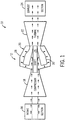
- FIG. 1 depicts an embodiment of a system 10 including a gas turbine engine 12 that may employ the microchannels noted above for cooling one or more shroud segments.
- the system 10 may include an aircraft, a watercraft, a locomotive, a power generation system, or combinations thereof.
- the illustrated gas turbine engine 12 includes an air intake section 16, a compressor 18, a combustor section 20, a turbine 22, and an exhaust section 24.
- the turbine 22 is coupled to the compressor 18 via a shaft 26.
- air may enter the gas turbine engine 12 through the intake section 16 and flow into the compressor 18, which compresses the air prior to entry into the combustor section 20.
- the illustrated combustor section 20 includes a combustor housing 28 disposed concentrically or annularly about the shaft 26 between the compressor 18 and the turbine 22.
- the compressed air from the compressor 18 enters combustors 30 where the compressed air may mix and combust with fuel within the combustors 30 to drive the turbine 22.
- multiple combustors 30 may be disposed in an annular arrangement within the combustor housing 28.
- the hot combustion gases flow through the turbine 22, driving the compressor 18 via the shaft 26.
- the combustion gases may apply motive forces to turbine rotor blades within the turbine 22 to rotate the shaft 26.
- the turbine 22 may include a plurality of shroud segments that contain and guide the combustion gases through the turbine 22.
- embodiments of the shroud segments include microchannels to cool various regions of the shroud segments, as will be discussed in detail below.
- the hot combustion gases may exit the gas turbine engine 12 through the exhaust section 24.
- FIG. 2 is a cross-sectional side view of an embodiment of the gas turbine engine 12 of FIG. 1 taken along a longitudinal axis 32.
- air enters the gas turbine engine 12 through the air intake section 16 and is compressed by the compressor 18.
- the compressed air from the compressor 18 is then directed to the combustors 30 to mix with a fluid fuel which combusts to generate hot combustion gases.
- multiple combustors 30 may be annularly disposed within the combustor section 20.
- Each combustor 30 may include a transition piece 33 that directs the hot combustion gases from the combustor 30 to the gas turbine 22.
- each transition piece 33 may generally lead to a hot gas path from the combustor 30 to the turbine 22.
- the gas turbine 22 includes three separate stages 34.
- Each stage 34 includes a set of blades 36 coupled to a rotor wheel 38 that are rotatably attached to the shaft 26 ( FIG. 1 ).
- Each set of blades 36 is disposed within a shroud 37, which contains the hot combustion gases to allow a motive force to be applied to the blades 36.
- the shroud 37 may include an annular arrangement of individual segments, each segment having one or more microchannels to allow a cooling fluid to pass through their respective bodies to provide beneficial cooling.
- the hot combustion gases are directed toward the blades 36 where the hot combustion gases may apply motive forces to the blades 36 to rotate the blades 36, thereby turning the shaft 26.
- the hot combustion gases may then exit the gas turbine 22 through the exhaust section 24.
- the microchannel-equipped shroud segments described herein may be employed in any suitable type of turbine with any number of stages and shafts.
- the microchannel-equipped shroud segments may be included in a single stage turbine, in a dual turbine that includes a low-pressure turbine and a high-pressure turbine, or in a multi-stage turbine with three or more stages.
- the microchannel-equipped shroud segments may be included in a gas turbine, a steam turbine, a hydroturbine, or any other turbine.
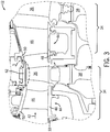
- FIG. 3 is a detailed view of an embodiment of the turbine 22 taken within line 3-3 of FIG. 2 .
- the hot combustion gases may flow from the combustors 30 ( FIG. 1 ) through the transition pieces 33 into the turbine 22 in a downstream direction 42.
- the turbine 22 includes nozzle assemblies 44 within each stage 34 to direct the hot combustion gases toward the blades 36.
- Each nozzle assembly 44 may include circumferentially spaced vanes 46 that extend between inner and outer band segments 48 and 50.
- band segments 48 and 50 may also be cooled using the microchannel cooling approaches described herein.
- Adjacent outer band segments 50 may be coupled together to form an outer annular ring extending around an inner annular ring of adjacent inner band segments 48.
- the vanes 46 may generally extend between the two annular rings formed by the inner and outer band segments 48 and 50.
- Shroud segments 52 that form the shroud 37 of FIG. 2 may be disposed downstream of the outer band segments 50 to direct hot combustion gases flowing past the vanes 46 to the blades 36.
- shroud segments 52 may be coupled together to form an outer annular ring (i.e., a shroud) that generally aligns with the outer annular ring formed by outer band segments 50.
- Discharge air from the compressor 18 ( FIG. 2 ) which may act as a cooling fluid, may be directed through the vanes 46, the inner and outer band segments 48 and 50, and the shroud segments 52 to provide cooling of the vanes 46, the inner and outer band segments 48 and 50, and the shroud segments 52.
- other cooling fluids may be used in addition to or in lieu of the discharge air, such as steam, recirculated exhaust gas, or fuel.
- the shroud segments 52 may be arranged circumferentially about the blades 36 to allow the hot combustion gases to provide motive forces to the blades 36. Accordingly, the discharge air from the compressor 18 ( FIG. 2 ) is provided as a cooling fluid to mitigate or control the buildup of thermal energy on the hot side of the shroud segments 52 facing the blades 36.
- the annular arrangement of the shroud segments 52 may be further appreciated with respect to FIG. 4 , which is a cross sectional view of the gas turbine engine 12 of FIG. 2 taken within section 4-4.
- each shroud segment 52 includes a main body 60 having a first surface 62 (e.g., a radially inner surface), a second surface 64 (e.g., a radially outer surface), and third surfaces 66 (e.g., lateral or circumferential interface surfaces).
- first surface 62 e.g., a radially inner surface
- second surface 64 e.g., a radially outer surface
- third surfaces 66 e.g., lateral or circumferential interface surfaces.
- the first surface 62 faces the blades 36 of FIG. 3 and, therefore, is the hot surface exposed to the hot combustion gases flowing through the turbine 22 ( FIG. 2 ).
- the second surface 64 faces away from the blades 36 and toward a flow of cooling fluid (e.g., the compressed air mentioned above), which facilitates cooling of the body 60 of the shroud segments 52.
- the third surfaces 66 connect the first surface 62 and the second surface 64, and face adjacent shroud segments 52 when the shroud ( FIG
- Each third surface 66 includes a seal slot 68, which is a recess in the third surface 66 that allows the body 60 of the shroud segment 52 to receive a portion of a seal 70.
- the seals 70 connect each shroud segment 52 with adjacent shroud segments 52, and provide a seal between adjacent shroud segments 52 to block the hot combustion gases from escaping.
- the body 60 may also include one or more flats, grooves, or recesses disposed in the body 60 proximate the seal slot 68, each of which may be used to form a cooling channel to cool the shroud segment 52.
- the shroud segment 52 includes a first channel 72 (e.g., a microchannel) disposed proximate the seal slot 68 between the seal slot 68 and the second surface 64.
- the first channel 72 may be formed by forming a flat, slot, groove, or recess 74 in the third surface 66, followed by covering the recess 74 with a layer 76, such as a cover layer. The process for forming the channels is discussed in further detail below with respect to FIGS. 19-26 .
- the shroud segments 52 may have channels disposed between the seal slot 68 and the first surface 62.
- the shroud segments 52 include second channels 78 (e.g., microchannels) formed by forming a recess 80 in the first surface 62 of the body 60, followed by covering the recess 80 with a layer 82.
- Layer 82 may be the same or different than the layer 76.
- the size of the second channels 78 may be the same or different than the size of the first channels 72.
- the first and second channels 72 and 78 may be microchannels having the same or different dimensions.
- the channels 72 and 78 may be microchannels having widths between approximately 50 microns ( ⁇ m) and 4 millimeters (mm) and depths between approximately 50 ⁇ m and 4 mm, as will be discussed below.
- the microchannels may have widths and/or depths between approximately 100 ⁇ m and 3.75 mm, between approximately 200 ⁇ m and 3.5 mm, or between approximately 300 ⁇ m and 2 mm.
- the microchannels may have widths and/or depths less than approximately 50, 100, 150, 200, 250, 300, 350, 400, 450, 500, 600, 700, or 750 ⁇ m.
- the microchannels may be any shape that may be formed using grooving, etching, or similar techniques. Indeed, the microchannels may have circular, semicircular, curved, or triangular, rhomboidal cross-sections in addition to or in lieu of the square or rectangular cross-sections as illustrated. The width and depth of the channel could vary throughout its length. Therefore, the disclosed flats, slots, grooves, or recesses may have straight or curved geometries consistent with such cross-sections. Moreover, in certain embodiments, the microchannels may have varying cross-sectional areas.
- forming microchannels from any one or a combination of the first surface 62 or the third surface 66 may allow such channels to be formed on the shroud segments 52 without substantially changing certain design considerations with regard to the shroud segments 52.
- the dimensions noted above may allow the first and second channels 72, 78 to be placed on the surfaces 62, 66 of the body 60 without substantially changing the position of certain features of the shroud segments 52, such as the seal slots 68.
- forming such microchannels from recesses in the various surfaces of the body 60 may allow the channels to be formed on existing or as-formed shroud segments, rather than using coring to form new shroud segments having larger channels deeper within the body 60.
- casting processes may be utilized to form one or more channels disposed within the body 60, for example to connect one or more of the second channels 78 with one or more first channels 72.
- connecting one of the first channels 72 with at least one of the second channels 78 may provide beneficial cooling of the shroud segment 52 proximate the seal slot 68.
- the placement of the channels 72, 78 may allow cooling of the shroud segments 52 in areas that may be otherwise difficult to cool.
- the second surface 64 may include one or more fluid orifices fluidly coupling the channels 72, 78 with the second surface 64. Therefore, cooling fluid flowing along and/or proximate the second surface 64 may flow through the fluid orifices and through the channels 72, 78.
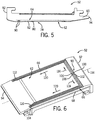
- FIG. 5 is a cross sectional view of the shroud segment 52 of FIG. 3 taken within section 5-5. Specifically, FIG. 5 depicts the pair of second channels 78 illustrated in FIG. 4 as fluidly coupled to the second surface 64 by two fluid orifices 90.
- the shroud segment 52 may include only one second channel 78 coupled to one or more fluid orifices 90, or the shroud segment 90 may include a plurality (e.g., 2 or more) second channels 78, with each second channel 78 being fluidly coupled to one or more fluid orifices 90.
- the number of first channels 72 ( FIG. 4 ) in each shroud segment 52 may be 1, 2, 3, 4, 5, 6, 7, 8, 9, 10 or more, with each first channel 72 being connected to one or more fluid orifices.
- the fluid orifices 90 may be approximately the same size or smaller than the channels 72, 78.
- the fluid orifices disclosed herein may have a diameter of between approximately 100 microns ( ⁇ m) and 4 millimeters (mm).
- the fluid orifices 90 may have diameters between approximately 50 ⁇ m and 4 mm, between approximately 250 ⁇ m and 3.25 mm, or between approximately 300 ⁇ m and 2 mm.
- the fluid orifices 90 could be larger than the channel, for example overlapping one or more channels. Additionally or alternatively, multiple small supply orifices could run along the channels.
- hot combustion gases may contact the first surface 62, which can increase the temperature of the first surface 62 and other features of the shroud segment 52 in contact with the first surface 62.
- compressed air flows as a cooling fluid along the second surface 64, through the fluid orifices 90, and to the second channels 78. More specifically, the hot combustion gases may first contact a leading end 92 of the shroud segment 52, flow along the first surface 62 and the layer 82, and past a trailing end 94 of the shroud segment 52.
- cooling fluid e.g., compressed air
- fluid orifices 90 flows along the second surface 64, through the fluid orifices 90, which are disposed closer to the leading end 92 than the trailing end 94, and into the channels 78.
- the placement of the fluid orifices 90 closer to the leading end 92 may cause the cooling fluid to flow within the channel 78 from the fluid orifices 90 in a path toward the trailing end 94.
- the cooling fluid may flow from the fluid orifices 90 through the channels 78 in a path toward the leading end 92.
- the flow paths that are formed from the recesses in the first surface 62 and the third surface 66 are discussed in further detail below.
- some or all of the channels disclosed herein and below with respect to FIGS. 9-16 may be configured to form channels that flow cooling fluid in opposite or alternating directions, which is not part of the present invention.
- FIG. 6 is a perspective view of an embodiment of the shroud segment 52 having the layer 82 removed to expose the recesses 80 (e.g., prior to placement of the layer 82).
- the shroud segment 52 may include one or more flow paths originating at the fluid orifices 90.
- the shroud segment 52 includes a first fluid orifice 100 and a second fluid orifice 102, disposed within an outer recess 104.
- the shroud segment 52 also includes a third fluid orifice 106 and a fourth fluid orifice 108 disposed within an inner recess 110.
- the outer recess 104 and the inner recess 110 are formed in a flat 112 that has been grooved into the first surface 62, as discussed below.
- the outer recess 104 and the inner recess 110 both extend in crosswise directions with respect to a longitudinal axis 114 of the shroud segment 52.
- the outer and inner recesses 104, 110 both extend in a first crosswise direction 116 and a second crosswise direction 118 toward the pair of third surfaces 66.
- the outer and inner recesses 104, 110 then turn to a first longitudinal direction 120 toward the trailing end 94 of the shroud segment 52.
- the outer and inner recesses 104, 110 both extend toward the pair of third surfaces 66, and are disposed on the first surface 62 proximate the seal slots 68.
- the outer and inner recesses 104, 110 may turn toward another direction, such as along an additional channel, before exiting (e.g., a channel running along the trailing end 94 of the shroud). Again, such a configuration may provide beneficial cooling to the areas proximate the seal slots 68, which may be difficult to accomplish in typical configurations not having channels.
- the fluid orifices 100, 102, 106, 108 may be angled with respect to the first surface 62. For example, angling any or a combination of the fluid orifices 100, 102, 106, 108 may facilitate the flow of cooling fluid through the outer and inner channels 104, 110 in both crosswise directions 116, 118.
- the first fluid orifice 100 and the third fluid orifice 106 may both be angled toward the third surface 66 along direction 116, while the second fluid orifice 102 and the fourth fluid orifice 108 may both be angled toward the third surface 66 along the direction 118.
- the angle of any or all of the fluid orifices 100, 102, 106, 108 may be between approximately 1 and 90 degrees, such as between approximately 10 and 75 degrees, approximately 15 and 60 degrees, or approximately 20 and 45 degrees from the first surface 62.
- FIG. 7 is a plan view of the shroud segment 52 illustrating an embodiment of the second surface 64.
- the illustrated embodiment depicts the second surface 64 as including the fluid orifices 100, 102, 106, 108, which lead to the outer and inner recesses 104, 110.
- cooling fluid flows along the second surface 64 and through the fluid orifices 100, 102, 106, 108, which lead to the channels that are formed from the recesses 104, 110.
- the manner in which the shroud segment 52 is cooled may depend on various factors including but not limited to the flow path defined by the recesses formed within the first surface 62 and/or the third surface 66, as well as the placement of the fluid orifices 100, 102, 106, 108. In certain embodiments, it may be desirable for the recesses 104, 110 to generally follow the seal slot 68 to provide beneficial cooling. Additionally, the placement of the fluid orifices 100, 102, 106, 108 may determine which areas of the shroud segment 52 receive the coolest air (i.e., the air that is entering the channels), and which areas may be designated as cooling fluid outlets.
- the coolest air i.e., the air that is entering the channels
- the fluid orifices 100, 102, 106, 108 may be placed closer to the leading end 92 or closer to the trailing end 94.
- a distance 130 between the first and second fluid orifices 100, 102 and the leading end 92 is smaller than a distance 132 between the first and second fluid orifices 100, 102 and the trailing end 94. Therefore, in the illustrated embodiment, the leading end 92, which may contact combustion gases having a higher temperature than those contacted at the trailing end 94, may receive fresh cooling fluid.
- the distance 130 may be greater than the distance 132. In such embodiments, the fluid orifices 100, 102, 106, 108 may be placed closer to the trailing end 94.
- the recesses 104, 110 may run longer or shorter along the first surface 62 and/or the third surface 66, with varying patterns, lengths, widths, and so on.
- one or more additional recesses may allow the flow to continue going along first surface 62, such as along the trailing end 94.
- FIG. 8 illustrates an embodiment of the recesses that are formed in the first surface 62
- FIGS: 9-16 illustrate various examples which do not belong to the invention.
- FIG. 8 illustrates a plan view of an embodiment of the shroud segment 52 having recesses 140 that extend from a forward area 142 proximate the leading edge 92 and toward the trailing edge 94. Therefore, the embodiment illustrated in FIG. 8 enables cooling channels to be formed through the trailing edge 94.
- fluid orifices 90 are illustrated as disposed at the forward area 142 proximate the leading edge 92, in other embodiments, the fluid orifices 90 may be positioned closer to the trailing edge 94, as noted above. In such embodiments, cooling fluid may flow from the trailing end 94 toward leading end 92. Moreover, as discussed below, the cooling channels may also run along both the trailing end 94 and the leading end 92, rather than only one end. In such a configuration, distance 132 of FIG.7 could be shorter than the distance 130 of FIG. 7 .
- FIG. 9 is a plan view illustrating an example of the shroud segment 52 having a single recess 150.
- Two fluid orifices 90 are disposed at the forward portion 142 of the shroud segment 52, each of which is configured to provide cooling fluid (e.g., air).
- the recess 150 may be formed into a channel that flows cooling fluid from a central portion 152 of the shroud segment 52 and outward toward each of the third surfaces 66 (i.e., the sides of the shroud segment 52) proximate the seal slot 68.
- the recess 150 extends toward the third surfaces 66 in this manner and then bends or turns to extend toward the trailing edge 94.
- the recess 150 may extend toward the trailing edge 94 substantially directly between the seal slot 68 ( FIG. 4 ) and the first surface 62 such that cooling fluid cools the seal slot.
- FIG. 10 is a plan view illustrating an example of the shroud segment 52 having a plurality of recesses 160 that converge and diverge. To provide a concise description of varying recess examples, only a portion of the shroud segment 52 is illustrated in FIGS. 10-16 .
- the plurality of recesses 160 may include 2, 3, 4, 5 ,6, 10, or more recesses
- the illustrated embodiment depicts three recesses 162, 164, 166 that each extend from fluid orifices 90 toward the third surface 66.
- the recesses 162, 164, 166 converge into a common recess 170.
- the common recess 170 extends toward the trailing edge 94 to a rear portion 172. While a portion of the common recess 170 extends to the trailing edge 94, a first diverging recess 174 and a second diverging recess 176 extend toward a center of the first surface 62, which is represented as a center line 178. The first and second diverging recesses 174, 176 then re-converge to form a second common recess 180 that extends to the trailing edge 94. It will be appreciated that such a configuration may provide beneficial cooling along a length 182 of the trailing edge 94, as opposed to only at a portion of the trailing edge 94 proximate the seal slot 68 ( FIG. 4 ).
- FIG. 11 illustrates a plan view of an example of the shroud segment 52 that is similar to the example illustrated in FIG. 10 .
- the recesses 162, 164, 166 converge in to the common recess 170 as in FIG. 10 , but the common recess 170 diverges into a first diverging path 184 and a second diverging path 186 that extend to the third surface 66.
- Such a configuration may enable a cooling channel to be formed that flows cooling fluid along a length proximate the seal slot 68 ( FIG. 4 ), and then outward to the third surface 66. This may provide beneficial cooling to the shroud segment 52 in areas between adjacent shroud segments 52 in addition to the areas proximate the seal slot 68.
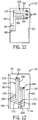
- FIG. 12 illustrates a plan view of such an example of the shroud segment 52.
- the illustrated example includes first and second recesses 190, 192 formed in the first surface 62.
- the first and second recesses 190, 192 each extend toward the trailing edge 94 from respective first and second fluid orifices 194, 196 disposed at different lengths 198, 200 from the trailing edge 94, and then bend or turn toward the third surface 66.
- the lengths 198, 200 may be the same or different.
- the lengths may differ by between 10% and 90%, such as between approximately 20% and 80%, approximately 30% and 70%, or approximately 40% and 60%. Additionally, the lengths 198, 200 may span between 10% and 90% of a length 199 of the first surface 62, such as between approximately 20% and 80%, approximately 30% and 70%, or approximately 40% and 60%.
- the first recess 190 includes a first portion 202 extending toward the trailing edge 94 and a second portion 204 extending from the first portion 202 at an angle 206.
- the first portion 202 may span substantially the entire length 199, or may span between approximately 20% and 90% of the length 199 prior to extending into the second portion 202.
- the first portion may span between approximately 30% and 80%, approximately 40% and 70%, or approximately 50% and 60% of the entire length 199.
- the angle 206 may be an acute or an obtuse angle.
- the angle 206 may be between approximately 1 and 180 degrees, such as between approximately 10 and 170 degrees, approximately 20 and 160 degrees, approximately 30 and 150 degrees, approximately 40 and 150 degrees, approximately 50 and 140 degrees, approximately 60 and 130 degrees, approximately 70 and 120 degrees, approximately 80 and 110 degrees, or approximately 90 and 100 degrees. Therefore, the first and second recesses 190, 192 may allow channels to be formed that are able, during operation, to direct the cooling fluid first toward the trailing edge 94 and then toward the third surface 66 (i.e., the sides of the shroud segment 52). This may enable portions of the shroud segment 52 having higher temperatures, such as the leading and trailing edges 92, 94 and side surfaces 66, to receive the coolest cooling fluid.
- the second recess 192 includes a first portion 208 and a second portion 210 extending from the first portion 208 at an angle 212. It will be appreciated that the geometrical relationships between the first portion 208 and the second portion 210 of the second recess 192 may include ranges that are similar or the same as those described above with respect to the first recess 190. Thus, the first portion 208 of the second recess 192 may span substantially the entire length 199, or may span between approximately 20% and 90% of the length 199 prior to extending into the second portion 210. For example, the first portion 208 may span between approximately 30% and 80%, approximately 40% and 70%, or approximately 50% and 60% of the entire length 199.
- the angle 212 may be an acute or an obtuse angle, such as the angles described above for angle 206.
- the fluid orifice 196 of the second recess 192 may be disposed closer to the third surface 66, which could provide counterflow of the cooling fluid.
- FIG. 13 is a plan view of an example of the shroud segment 52 having first and second recesses 220, 222 that extend from respective fluid orifices 224, 226 in zig-zag patterns toward the trailing edge 94.
- the first and second fluid orifices 224, 226 are disposed at different lengths 228, 230 from the trailing edge 94.
- the lengths 228, 230 may be the same.
- the lengths 228, 230 may span between 10% and 90% of the length 199 of the first surface 62, such as between approximately 20% and 80%, approximately 30% and 70%, or approximately 40% and 60%.
- the first recess 220 extends from the fluid orifice 224 toward the trailing edge 94, and turns toward and ends at the third surface 66.
- two adjoining recesses, such as the first and second recesses 220, 222 could be connected proximate the third surface 66 such that flow runs down one recess then back up the other to exit. Additional recesses could similarly be connected allowing two, three, or more passes for coolant to flow up and down the surface or part of the surface.
- the first recess 220 may extend from the fluid orifice 224 toward the leading edge 92, and then turn toward the third surface 66.
- FIG. 14 is a plan view of an example of the shroud segment 52 having a plurality of recesses 232 extending in substantially straight lines from a plurality of fluid orifices 234 to the trailing edge 94.
- the plurality of recesses 232 are disposed in a substantially parallel fashion with respect to each other and the third surface 66.
- each of the fluid orifices 234 may be located at equal or different positions between approximately 1% and 99% of the length 199 of the shroud segment 52.
- the recesses 232 may extend equal or different lengths 233 between approximately 10% and 90%, approximately 20% and 80%, approximately 30% and 70%, or approximately 40% and 60% of the length 199. Again as noted above, it may be desirable in some embodiments to alternate the flow of cooling fluid along the first surface 62.
- some or all of the recesses 232 may extend toward the leading edge 92 rather than the trailing edge 94. In other embodiments, the recesses 232 may extend from side to side, i.e., from one third surface 66 to the other surface 66. In certain of these embodiments, some or all of the recesses 232 may be aligned substantially parallel to the trailing ends 92, 94.
- FIG. 15 is a plan view of an example of the shroud segment 52 having a first plurality of recesses 240 that converge to a common recess 242, and a second plurality of recesses 244 that converge to a second common recess 246.
- the first and second common recesses 242, 246 may enable cooling along the entire length, or at least substantially the entire length, of the trailing edge 94.
- the first plurality of recesses 240 extend toward the trailing edge 94 from first fluid orifices 248.
- the first plurality of recesses 240 then converge to the first common recess 242, which extends in a first direction 250 toward the third surface 66.
- the second plurality of recesses 244 extend toward the trailing edge 94 from second fluid orifices 252.
- the second plurality of recesses 244 then converge to the first common recess 246, which extends in a second direction 254 toward the third surface 66.
- Such a configuration allows cooling fluid to flow in the second direction 254 along the trailing edge 94 and exit the shroud segment 52 at the third surface 66.
- a similar configuration could be used around the leading end 92.
- FIG. 16 illustrates the shroud segment 52 having a recess 260 extending from a fluid orifice 262 toward the leading edge 92.
- the recess 260 then extends toward the third surface 66, followed by another bend toward the trailing edge 94 and generally following the positioning of the seal slot 68 ( FIG. 4 ).
- the recess 260 may extend fully or partially toward the trailing edge 94.
- the recess 260 may extend fully or partially toward the third surface 66. In the illustrated example, the recess 260 terminates at the third surface 66. Therefore, the recess 260 may allow beneficial cooling of the shroud segment 52 proximate the areas mentioned above.
- the channels used for cooling may be formed from one or more recesses within the first surface 62, the second surface 64, or the third surface 66, or a combination thereof.
- the recesses may be grooved out of these surfaces and covered with a layer to form the channels.
- the channels may be formed using any method capable of forming recesses in a surface, such as etching, grinding, grooving, waterjet, laser, or EDM. Accordingly, non-limiting examples of methods for forming the disclosed channels are discussed with respect to FIGS. 17-24 . Again, these channels may allow cooling fluid to be flowed through the body 60 ( FIG. 4 ) of the shroud segment 52 in which they are formed.
- FIG. 17 is a cutaway view of a portion of an as-formed shroud segment 270, such as a shroud segment produced as part of a casting or other shroud segment-forming procedure.
- the as-formed shroud segment 270 includes the first surface 62, the second surface 64, and the opposite third surfaces 66 as discussed above. Additionally, the as-formed shroud segment 270 includes the seal slot 68.
- the disclosed methods do not form the seal slot 68 prior to forming the disclosed channels (e.g., microchannels).
- the as-formed shroud segment 270 may be machined to generate a machined shroud segment 272.
- the machined shroud segment 272 includes one or more recesses 274, which may be used to form the channels described herein.
- each of the recesses 274 may have widths between approximately 50 microns ( ⁇ m) and 4 millimeters (mm) and depths between approximately 50 ⁇ m and 4 mm.
- the recesses 274 may have widths and/or depths between approximately 100 ⁇ m and 3.75 mm, between approximately 200 ⁇ m and 3.5 mm, or between approximately 300 ⁇ m and 2 mm.
- the recesses 274 may be covered with a covering layer. Prior to applying the layer, however, it may be desirable to fill the recesses 274 with a filler material to avoid layer material encroaching into the recesses 274.
- FIG. 19 illustrates an embodiment of the shroud segment 272 having filler material 276 disposed within the recesses 274.
- the filler material 276 may be a material that can be selectively withdrawn with respect to the layer that will be disposed over the recesses 274.
- the filler material 276 may include a metal-based material (e.g., a copper based compound) that can be leached out
- a topcoat 278, such as a bondcoat may be applied either to the entire first surface 62, or on top of an area encompassing the recesses 274. Due to the specific tolerances within the turbine 22 ( FIGS. 1-3 ), it may be desirable to apply the topcoat 278 in a thickness that may not substantially affect the performance of the shroud segment that results from the method disclosed herein.
- the thickness of the topcoat 278 may be between approximately 10 ⁇ m and 1 mm.
- the thickness of the topcoat 278 may be between approximately 50 ⁇ m and 1 mm, approximately 100 ⁇ m and 500 ⁇ m, approximately 200 ⁇ m and 400 ⁇ m, or approximately 250 ⁇ m and 350 ⁇ m.
- FIG. 21 illustrates a microchannel equipped shroud segment 280 having a pair of cooling channels 282 that are formed by removing the filler material 276 from the recesses 274 after applying the topcoat 278.
- the filler material 276 may be removed using an aqueous and/or organic solvent.
- the as-formed shroud segment 270 described with respect to FIG. 17 may be machined to form a machined shroud segment 290, which is illustrated in FIG. 22 .
- the machined shroud segment 290 includes a platform recess 292, which may be considered a support for a cover insert, as will be described below, having a width 294 that is sufficient to allow a desired number of recesses to be formed within the platform recess 292.
- the width 294 may allow 1, 2, 3, 4, 5, 6, 8, 9, 10 or more recesses to be formed.
- FIG. 23 illustrates an embodiment of a shroud segment 296 that has been machined or otherwise treated to form recesses 298 in the platform recess 292 at an offset distance 299 from the first surface 62.
- the distance 299 may be the depth of the platform recess 292, and may be between approximately 4 mm and 50 ⁇ m, 3.75 mm and 100 ⁇ m, or 3.5 mm and 200 ⁇ m.
- the recess 292 may be less than approximately 2 mm, 1.75 mm, 1.5 mm, 1 mm, 750 ⁇ m, 500 ⁇ m, 400 ⁇ m, 300 ⁇ m, 250 ⁇ m, 200 ⁇ m, 150 ⁇ m, or 100 ⁇ m.
- the recesses 298 may have widths between approximately 50 ⁇ m and 4 mm and depths between approximately 50 ⁇ m and 4 mm.
- the recesses 298 may have widths and/or depths between approximately 150 ⁇ m and 3.5 mm, between approximately 250 ⁇ m and 3.25 mm, or between approximately 300 ⁇ m and 2 mm.
- the recesses 298 may be covered with a cover layer 300 to generate a shroud segment 302 having a pair of cooling channels 304.
- the cooling channels 304 may be microchannels having the dimensions mentioned above with respect to the recesses 298.
- the layer 300 may be a metallic layer that is brazed, welded, or otherwise secured to the shroud segment 302.
- the metallic layer may be of similar material to the base shroud.
- the metallic layer may include alloys, such as nickel or cobalt base superalloys.
- the layer 300, after being secured to the shroud segment 302, may be ground, milled, or otherwise machined down to a desired tolerance.
- the cover layer 300 may have a thickness that is substantially the same as the depth described above for the offset distance 299, which is less than approximately 4 mm, such as between approximately 4 mm and 50 ⁇ m, 3.75 mm and 100 ⁇ m, or 3.5 mm and 200 ⁇ m.
Description
- The subject matter disclosed herein relates to cooling parts of a turbine engine, and, more specifically, to cooling shroud segments of the gas turbine engine.
- In general, gas turbines combust a mixture of compressed air and fuel to produce hot combustion gases. The combustion gases may flow through one or more turbines to generate power to drive a load, such as an electrical generator and/or a compressor. Within the gas turbines, the combustion gases may flow through one or more stages of nozzles and blades. The turbine nozzles may include circumferential rings of vanes that direct the combustion gases to the blades. As the combustion gases flow past the blades, the combustion gases drive the blades to rotate, thereby driving the load. The hot combustion gases may be contained using circumferential shrouds surrounding the blades, which also aid in directing a flow of the hot combustion gases through the gas turbine engine. Unfortunately, it is difficult to cool certain regions of the shrouds, such as intermediate seal regions between shroud segments. As a result, the shroud may be subject to hot spots and high thermal stresses in these regions.
- In
EP 2 045 445 a blade outer air seal casting core is disclosed that has first and second end portions and a plurality of legs. Of these legs, first legs each have: a proximal end joining the first end portion; a main body portion; and a free distal portion. Second legs each have: a proximal end joining the second end portion; a main body portion; and a free distal portion. Diverging branches are provided for forming diverging outlet passages in a blade outer air seal segment cast from the core. - In
US 2005/058534 a turbine wall is disclosed that includes a metal substrate having front and back surfaces. A thermal barrier coating is bonded atop the front surface. A network of flow channels is laminated between the substrate and the coating for carrying an air coolant therebetween for cooling the thermal barrier coating. - Certain embodiments commensurate in scope with the claimed subject matter are summarized below. These embodiments are not intended to limit the scope of the claims, but rather these embodiments are intended only to provide a brief summary of possible forms of the present disclosure. Indeed, the embodiments described herein may encompass a variety of forms that may be similar to or different from the embodiments set forth below.
- In a first aspect, the invention resides in a system according to claim 1.
- In a second aspect, the invention resides in a method according to claim 9.
- Embodiments of the present invention will now be described, by way of example only, with reference to the accompanying drawings in which:
-
FIG. 1 is a schematic flow diagram of an embodiment of a gas turbine engine that may employ shroud segments having cooling channels; -
FIG. 2 is a sectional view of the gas turbine engine ofFIG. 1 sectioned through a longitudinal axis of the engine; -
FIG. 3 is a partial sectional view of the gas turbine engine ofFIG. 2 taken within line 3-3 and showing an embodiment of a turbine stage having a plurality of shroud segments; -
FIG. 4 is a partial sectional view of the gas turbine engine ofFIG. 2 taken within line 4-4 and showing an embodiment of a plurality of shroud segments having cooling channels; -
FIG. 5 is a side cross-sectional view of the shroud segment ofFIG. 3 taken within line 5-5 and showing an embodiment of a plurality of fluid orifices leading to a plurality of cooling channels; -
FIG. 6 is a perspective view of an embodiment of a shroud segment having a plurality of recesses that may be used to form cooling channels on a turbine blade-facing surface of the shroud segment; -
FIG. 7 is a plan view of a front surface of the shroud segment ofFIG. 6 and showing an embodiment of a plurality of fluid orifices leading to the plurality of cooling channels; -
FIG. 8 is a plan view of another embodiment of a turbine blade-facing surface of a shroud segment having a plurality of recesses that may be used to form a plurality of cooling channels; -
FIG. 9 is a plan view of an example of a turbine blade-facing surface of a shroud segment having a recesses that may be used to form a cooling channel; -
FIG. 10 is a plan view of another example of a turbine blade-facing surface of a shroud segment having a plurality of recesses that converge to flow along a side of the shroud segment and then diverge at an end distal from the fluid orifices of the recesses; -
FIG. 11 is a plan view of another example of a turbine blade-facing surface of a shroud segment having recesses that converge to flow along a side of the shroud segment and then diverge toward a side of the shroud segment; -
FIG. 12 is a plan view of another example of a turbine blade-facing surface of a shroud segment having recesses that extend along a length of the shroud segment and then bend toward a side of the shroud segment; -
FIG. 13 is a plan view of another example of a turbine blade-facing surface of a shroud segment having recesses that zig-zag along a length of the shroud segment; -
FIG. 14 is a plan view of another example of a turbine blade-facing surface of a shroud segment having recesses that run substantially parallel along a length of the shroud segment; -
FIG. 15 is a plan view of another example of a turbine blade-facing surface of a shroud segment having recesses that converge at an end of the shroud segment and then diverge toward a side of the shroud segment; -
FIG. 16 is a plan view of another example of a turbine blade-facing surface of a shroud segment having recesses that extend toward a leading end of the shroud segment, then bend to extend toward a trailing end of the shroud segment, and then bend again to extend to a side of the shroud segment; -
FIG. 17 is a cutaway view of an embodiment of a shroud segment prior to forming cooling channels; -
FIG. 18 is a cutaway view of an embodiment of the shroud segment ofFIG. 17 after recesses have been formed; -
FIG. 19 is a cutaway view of an embodiment of the shroud segment ofFIG. 18 after the recesses have been filled with a filler material; -
FIG. 20 is a cutaway view of an embodiment of the shroud segment ofFIG. 19 after the recesses have been covered with a layer; -
FIG. 21 is a cutaway view of an embodiment of the shroud segment ofFIG. 20 after the filler material has been removed from the recesses to form the cooling channels; -
FIG. 22 is a cutaway view of an embodiment of a shroud segment having grooved flats prior to forming cooling channels; -
FIG. 23 is a cutaway view of an embodiment of the shroud segment ofFIG. 22 after recesses have been formed in the grooved flats; and -
FIG. 24 is a cutaway view of en embodiment of the shroud segment ofFIG. 23 after a braze layer has been applied in the grooved flats to cover the recesses to form the cooling channels. - The examples in
figures 9-16 do not belong the invention. - One or more specific embodiments of the present invention will be described below. In an effort to provide a concise description of these embodiments, all features of an actual implementation may not be described in the specification. It should be appreciated that in the development of any such actual implementation, as in any engineering or design project, numerous implementation-specific decisions must be made to achieve the developers' specific goals, such as compliance with system-related and business-related constraints, which may vary from one implementation to another. Moreover, it should be appreciated that such a development effort might be complex and time consuming, but would nevertheless be a routine undertaking of design, fabrication, and manufacture for those of ordinary skill having the benefit of this disclosure.
- As noted above, in certain gas turbine engine embodiments, circumferential segments, which may form one or more annular shrouds, may surround turbine blades of the turbine engine. The shrouds, in a general sense, contain the hot combustion gases produced at the combustors of the gas turbine engine and also direct a flow of the combustion gases through a turbine section of the turbine engine. Therefore, during operation, the segments that form the annular shrouds, referred to herein as shroud segments, may heat to temperatures approaching those of the hot combustion gases. Unfortunately, in situations where such heating is not mitigated or controlled, the shroud may deteriorate, which can result in a decrease in performance or engine downtime. In some configurations, the shrouds may be cooled using cooling fluids that flow against a surface of the shroud segments that are opposite the surfaces that face the turbine blades. However, such cooling may not be sufficient to cool all portions of the shroud segments. Accordingly, the present disclosure provides embodiments where cooling channels, such as microchannels, are used to direct one or more flows of cooling fluid through a body of the shroud segments. Such channeling may allow cooling fluid to flow to portions of shroud segments that may otherwise be difficult to cool, such as areas proximate seal slots, trailing and/or leading edges, and so forth.
- It should be noted that while the present embodiments are described in the context of a gas turbine engine, the embodiments disclosed herein may also be used in conjunction with other turbomachinery having heated fluids, such as steam turbine engines. Moreover, while the present embodiments are discussed in the context of shroud segments disposed downstream from combustors of a gas turbine engine, it should be noted that the approaches described herein are also applicable to other shrouds and/or airfoils, such as shrouds disposed proximate a nozzle region of the gas turbine engine. Keeping in mind that the present embodiments are also applicable in such contexts,
FIG. 1 depicts an embodiment of asystem 10 including agas turbine engine 12 that may employ the microchannels noted above for cooling one or more shroud segments. In certain embodiments, thesystem 10 may include an aircraft, a watercraft, a locomotive, a power generation system, or combinations thereof. The illustratedgas turbine engine 12 includes anair intake section 16, acompressor 18, acombustor section 20, aturbine 22, and anexhaust section 24. Theturbine 22 is coupled to thecompressor 18 via ashaft 26. - As indicated by the arrows, air may enter the
gas turbine engine 12 through theintake section 16 and flow into thecompressor 18, which compresses the air prior to entry into thecombustor section 20. The illustratedcombustor section 20 includes acombustor housing 28 disposed concentrically or annularly about theshaft 26 between thecompressor 18 and theturbine 22. The compressed air from thecompressor 18 enterscombustors 30 where the compressed air may mix and combust with fuel within thecombustors 30 to drive theturbine 22. According to certain embodiments,multiple combustors 30 may be disposed in an annular arrangement within thecombustor housing 28. - From the
combustor section 20, the hot combustion gases flow through theturbine 22, driving thecompressor 18 via theshaft 26. For example, the combustion gases may apply motive forces to turbine rotor blades within theturbine 22 to rotate theshaft 26. As noted above, theturbine 22 may include a plurality of shroud segments that contain and guide the combustion gases through theturbine 22. Furthermore, embodiments of the shroud segments include microchannels to cool various regions of the shroud segments, as will be discussed in detail below. After flowing through theturbine 22, the hot combustion gases may exit thegas turbine engine 12 through theexhaust section 24. -
FIG. 2 is a cross-sectional side view of an embodiment of thegas turbine engine 12 ofFIG. 1 taken along alongitudinal axis 32. As described above with respect toFIG. 1 , air enters thegas turbine engine 12 through theair intake section 16 and is compressed by thecompressor 18. The compressed air from thecompressor 18 is then directed to thecombustors 30 to mix with a fluid fuel which combusts to generate hot combustion gases. As noted above,multiple combustors 30 may be annularly disposed within thecombustor section 20. Eachcombustor 30 may include atransition piece 33 that directs the hot combustion gases from thecombustor 30 to thegas turbine 22. In particular, eachtransition piece 33 may generally lead to a hot gas path from thecombustor 30 to theturbine 22. - As depicted, the
gas turbine 22 includes threeseparate stages 34. Eachstage 34 includes a set ofblades 36 coupled to arotor wheel 38 that are rotatably attached to the shaft 26 (FIG. 1 ). Each set ofblades 36 is disposed within ashroud 37, which contains the hot combustion gases to allow a motive force to be applied to theblades 36. Again, as will be discussed below, theshroud 37 may include an annular arrangement of individual segments, each segment having one or more microchannels to allow a cooling fluid to pass through their respective bodies to provide beneficial cooling. The hot combustion gases are directed toward theblades 36 where the hot combustion gases may apply motive forces to theblades 36 to rotate theblades 36, thereby turning theshaft 26. The hot combustion gases may then exit thegas turbine 22 through theexhaust section 24. - Although the
turbine 22 is illustrated as a three-stage turbine, the microchannel-equipped shroud segments described herein may be employed in any suitable type of turbine with any number of stages and shafts. For example, the microchannel-equipped shroud segments may be included in a single stage turbine, in a dual turbine that includes a low-pressure turbine and a high-pressure turbine, or in a multi-stage turbine with three or more stages. Furthermore, the microchannel-equipped shroud segments may be included in a gas turbine, a steam turbine, a hydroturbine, or any other turbine. -
FIG. 3 is a detailed view of an embodiment of theturbine 22 taken within line 3-3 ofFIG. 2 . During operation, the hot combustion gases may flow from the combustors 30 (FIG. 1 ) through thetransition pieces 33 into theturbine 22 in adownstream direction 42. Theturbine 22 includesnozzle assemblies 44 within eachstage 34 to direct the hot combustion gases toward theblades 36. Eachnozzle assembly 44 may include circumferentially spacedvanes 46 that extend between inner andouter band segments band segments outer band segments 50 may be coupled together to form an outer annular ring extending around an inner annular ring of adjacentinner band segments 48. Thevanes 46 may generally extend between the two annular rings formed by the inner andouter band segments -
Shroud segments 52 that form theshroud 37 ofFIG. 2 may be disposed downstream of theouter band segments 50 to direct hot combustion gases flowing past thevanes 46 to theblades 36. In particular,shroud segments 52 may be coupled together to form an outer annular ring (i.e., a shroud) that generally aligns with the outer annular ring formed byouter band segments 50. Discharge air from the compressor 18 (FIG. 2 ), which may act as a cooling fluid, may be directed through thevanes 46, the inner andouter band segments shroud segments 52 to provide cooling of thevanes 46, the inner andouter band segments shroud segments 52. In some embodiments, other cooling fluids may be used in addition to or in lieu of the discharge air, such as steam, recirculated exhaust gas, or fuel. - Again, the
shroud segments 52 may be arranged circumferentially about theblades 36 to allow the hot combustion gases to provide motive forces to theblades 36. Accordingly, the discharge air from the compressor 18 (FIG. 2 ) is provided as a cooling fluid to mitigate or control the buildup of thermal energy on the hot side of theshroud segments 52 facing theblades 36. The annular arrangement of theshroud segments 52 may be further appreciated with respect toFIG. 4 , which is a cross sectional view of thegas turbine engine 12 ofFIG. 2 taken within section 4-4. In the illustrated embodiment, eachshroud segment 52 includes amain body 60 having a first surface 62 (e.g., a radially inner surface), a second surface 64 (e.g., a radially outer surface), and third surfaces 66 (e.g., lateral or circumferential interface surfaces). When assembled in thegas turbine engine 12, thefirst surface 62 faces theblades 36 ofFIG. 3 and, therefore, is the hot surface exposed to the hot combustion gases flowing through the turbine 22 (FIG. 2 ). Conversely, thesecond surface 64 faces away from theblades 36 and toward a flow of cooling fluid (e.g., the compressed air mentioned above), which facilitates cooling of thebody 60 of theshroud segments 52. The third surfaces 66 connect thefirst surface 62 and thesecond surface 64, and faceadjacent shroud segments 52 when the shroud (FIG. 2 ) is assembled. - Each
third surface 66 includes aseal slot 68, which is a recess in thethird surface 66 that allows thebody 60 of theshroud segment 52 to receive a portion of aseal 70. Theseals 70 connect eachshroud segment 52 withadjacent shroud segments 52, and provide a seal betweenadjacent shroud segments 52 to block the hot combustion gases from escaping. In some embodiments, thebody 60 may also include one or more flats, grooves, or recesses disposed in thebody 60 proximate theseal slot 68, each of which may be used to form a cooling channel to cool theshroud segment 52. For example, in the illustrated embodiment, theshroud segment 52 includes a first channel 72 (e.g., a microchannel) disposed proximate theseal slot 68 between theseal slot 68 and thesecond surface 64. In certain embodiments, thefirst channel 72 may be formed by forming a flat, slot, groove, orrecess 74 in thethird surface 66, followed by covering therecess 74 with alayer 76, such as a cover layer. The process for forming the channels is discussed in further detail below with respect toFIGS. 19-26 . - Additionally or alternatively, the
shroud segments 52 may have channels disposed between theseal slot 68 and thefirst surface 62. According to the invention, theshroud segments 52 include second channels 78 (e.g., microchannels) formed by forming arecess 80 in thefirst surface 62 of thebody 60, followed by covering therecess 80 with alayer 82.Layer 82 may be the same or different than thelayer 76. Moreover, the size of thesecond channels 78 may be the same or different than the size of thefirst channels 72. Indeed, in certain embodiments, the first andsecond channels channels - Advantageously, forming microchannels from any one or a combination of the
first surface 62 or thethird surface 66 may allow such channels to be formed on theshroud segments 52 without substantially changing certain design considerations with regard to theshroud segments 52. For example, the dimensions noted above may allow the first andsecond channels surfaces body 60 without substantially changing the position of certain features of theshroud segments 52, such as theseal slots 68. Moreover, forming such microchannels from recesses in the various surfaces of thebody 60 may allow the channels to be formed on existing or as-formed shroud segments, rather than using coring to form new shroud segments having larger channels deeper within thebody 60. That is, forming channels using coring techniques may require a larger thickness between the channel and thefirst surface 62 than is suitable using microchannels in accordance with the presently contemplated embodiments. However, in certain embodiments, casting processes may be utilized to form one or more channels disposed within thebody 60, for example to connect one or more of thesecond channels 78 with one or morefirst channels 72. For example, connecting one of thefirst channels 72 with at least one of thesecond channels 78 may provide beneficial cooling of theshroud segment 52 proximate theseal slot 68. Indeed, the placement of thechannels shroud segments 52 in areas that may be otherwise difficult to cool. - To allow cooling fluid (e.g., compressed air, oxygen enriched air, steam, recirculated exhaust gas, fuel) to flow through each of the
channels second surface 64 may include one or more fluid orifices fluidly coupling thechannels second surface 64. Therefore, cooling fluid flowing along and/or proximate thesecond surface 64 may flow through the fluid orifices and through thechannels FIG. 5 , which is a cross sectional view of theshroud segment 52 ofFIG. 3 taken within section 5-5. Specifically,FIG. 5 depicts the pair ofsecond channels 78 illustrated inFIG. 4 as fluidly coupled to thesecond surface 64 by twofluid orifices 90. However, while twosecond channels 78 and twofluid orifices 90 are presently depicted, it should be noted that theshroud segment 52 may include only onesecond channel 78 coupled to one or morefluid orifices 90, or theshroud segment 90 may include a plurality (e.g., 2 or more)second channels 78, with eachsecond channel 78 being fluidly coupled to one or morefluid orifices 90. Indeed, the number of first channels 72 (FIG. 4 ) in eachshroud segment 52 may be 1, 2, 3, 4, 5, 6, 7, 8, 9, 10 or more, with eachfirst channel 72 being connected to one or more fluid orifices. Additionally, thefluid orifices 90 may be approximately the same size or smaller than thechannels fluid orifices 90 may have diameters between approximately 50 µm and 4 mm, between approximately 250 µm and 3.25 mm, or between approximately 300 µm and 2 mm. In some embodiments, thefluid orifices 90 could be larger than the channel, for example overlapping one or more channels. Additionally or alternatively, multiple small supply orifices could run along the channels. - With regard to the
shroud segment 52 illustrated inFIG. 5 , during operation of the gas turbine engine 12 (FIGS. 1 and2 ), hot combustion gases may contact thefirst surface 62, which can increase the temperature of thefirst surface 62 and other features of theshroud segment 52 in contact with thefirst surface 62. To counteract such heating, compressed air flows as a cooling fluid along thesecond surface 64, through thefluid orifices 90, and to thesecond channels 78. More specifically, the hot combustion gases may first contact aleading end 92 of theshroud segment 52, flow along thefirst surface 62 and thelayer 82, and past a trailingend 94 of theshroud segment 52. Likewise, in the illustrated embodiment, cooling fluid (e.g., compressed air) flows along thesecond surface 64, through thefluid orifices 90, which are disposed closer to theleading end 92 than the trailingend 94, and into thechannels 78. The placement of thefluid orifices 90 closer to theleading end 92 may cause the cooling fluid to flow within thechannel 78 from thefluid orifices 90 in a path toward the trailingend 94. Additionally in some embodiments, the cooling fluid may flow from thefluid orifices 90 through thechannels 78 in a path toward the leadingend 92. The flow paths that are formed from the recesses in thefirst surface 62 and thethird surface 66 are discussed in further detail below. Moreover, it should be noted that some or all of the channels disclosed herein and below with respect toFIGS. 9-16 may be configured to form channels that flow cooling fluid in opposite or alternating directions, which is not part of the present invention. -
FIG. 6 is a perspective view of an embodiment of theshroud segment 52 having thelayer 82 removed to expose the recesses 80 (e.g., prior to placement of the layer 82). As noted above, theshroud segment 52 may include one or more flow paths originating at thefluid orifices 90. In the illustrated embodiment, theshroud segment 52 includes a firstfluid orifice 100 and a secondfluid orifice 102, disposed within anouter recess 104. Theshroud segment 52 also includes a thirdfluid orifice 106 and a fourthfluid orifice 108 disposed within aninner recess 110. In the illustrated embodiment, theouter recess 104 and theinner recess 110 are formed in a flat 112 that has been grooved into thefirst surface 62, as discussed below. Theouter recess 104 and theinner recess 110 both extend in crosswise directions with respect to a longitudinal axis 114 of theshroud segment 52. For example, the outer andinner recesses crosswise direction 116 and a secondcrosswise direction 118 toward the pair of third surfaces 66. The outer andinner recesses longitudinal direction 120 toward the trailingend 94 of theshroud segment 52. The outer andinner recesses third surfaces 66, and are disposed on thefirst surface 62 proximate theseal slots 68. In some embodiments, the outer andinner recesses end 94 of the shroud). Again, such a configuration may provide beneficial cooling to the areas proximate theseal slots 68, which may be difficult to accomplish in typical configurations not having channels. - To facilitate cooling of the
shroud segment 52 proximate the seal slots 68 (among other regions of the shroud segment 52), thefluid orifices first surface 62. For example, angling any or a combination of thefluid orifices inner channels directions fluid orifice 100 and the thirdfluid orifice 106 may both be angled toward thethird surface 66 alongdirection 116, while the secondfluid orifice 102 and the fourthfluid orifice 108 may both be angled toward thethird surface 66 along thedirection 118. As an example, the angle of any or all of thefluid orifices first surface 62. -
FIG. 7 is a plan view of theshroud segment 52 illustrating an embodiment of thesecond surface 64. Specifically, the illustrated embodiment depicts thesecond surface 64 as including thefluid orifices inner recesses second surface 64 and through thefluid orifices recesses shroud segment 52 is cooled may depend on various factors including but not limited to the flow path defined by the recesses formed within thefirst surface 62 and/or thethird surface 66, as well as the placement of thefluid orifices recesses seal slot 68 to provide beneficial cooling. Additionally, the placement of thefluid orifices shroud segment 52 receive the coolest air (i.e., the air that is entering the channels), and which areas may be designated as cooling fluid outlets. Again, thefluid orifices leading end 92 or closer to the trailingend 94. In the illustrated embodiment, adistance 130 between the first and secondfluid orifices leading end 92 is smaller than adistance 132 between the first and secondfluid orifices end 94. Therefore, in the illustrated embodiment, the leadingend 92, which may contact combustion gases having a higher temperature than those contacted at the trailingend 94, may receive fresh cooling fluid. However, in other embodiments, thedistance 130 may be greater than thedistance 132. In such embodiments, thefluid orifices end 94. Alternatively or additionally, therecesses first surface 62 and/or thethird surface 66, with varying patterns, lengths, widths, and so on. In some embodiments, one or more additional recesses may allow the flow to continue going alongfirst surface 62, such as along the trailingend 94. Keeping in mind that the recesses may be formed in thefirst surface 62 and/or thethird surface 66 in a variety of configurations,FIG. 8 illustrates an embodiment of the recesses that are formed in thefirst surface 62FIGS: 9-16 illustrate various examples which do not belong to the invention. - During operation of the
gas turbine engine 10 ofFIG. 1 , various edges, such as the trailingedge 94, among others, may experience an increased amount of exposure to hot gases compared to other surfaces. Therefore, as noted above, sides, corners, edges, and so forth may develop hot spots/regions.FIG. 8 illustrates a plan view of an embodiment of theshroud segment 52 havingrecesses 140 that extend from aforward area 142 proximate theleading edge 92 and toward the trailingedge 94. Therefore, the embodiment illustrated inFIG. 8 enables cooling channels to be formed through the trailingedge 94. Furthermore, while thefluid orifices 90 are illustrated as disposed at theforward area 142 proximate theleading edge 92, in other embodiments, thefluid orifices 90 may be positioned closer to the trailingedge 94, as noted above. In such embodiments, cooling fluid may flow from the trailingend 94 toward leadingend 92. Moreover, as discussed below, the cooling channels may also run along both the trailingend 94 and theleading end 92, rather than only one end. In such a configuration,distance 132 ofFIG.7 could be shorter than thedistance 130 ofFIG. 7 . -
FIG. 9 is a plan view illustrating an example of theshroud segment 52 having asingle recess 150. Twofluid orifices 90 are disposed at theforward portion 142 of theshroud segment 52, each of which is configured to provide cooling fluid (e.g., air). In the illustrated example therecess 150 may be formed into a channel that flows cooling fluid from acentral portion 152 of theshroud segment 52 and outward toward each of the third surfaces 66 (i.e., the sides of the shroud segment 52) proximate theseal slot 68. Therecess 150 extends toward thethird surfaces 66 in this manner and then bends or turns to extend toward the trailingedge 94. Specifically, in some embodiments, therecess 150 may extend toward the trailingedge 94 substantially directly between the seal slot 68 (FIG. 4 ) and thefirst surface 62 such that cooling fluid cools the seal slot. -
FIG. 10 is a plan view illustrating an example of theshroud segment 52 having a plurality ofrecesses 160 that converge and diverge. To provide a concise description of varying recess examples, only a portion of theshroud segment 52 is illustrated inFIGS. 10-16 . Keeping in mind that the plurality ofrecesses 160 may include 2, 3, 4, 5 ,6, 10, or more recesses, the illustrated embodiment depicts threerecesses fluid orifices 90 toward thethird surface 66. At anarea 168, which in some embodiments may be proximate the seal slot 68(FIG. 4 ), therecesses common recess 170. Thecommon recess 170 extends toward the trailingedge 94 to arear portion 172. While a portion of thecommon recess 170 extends to the trailingedge 94, a first divergingrecess 174 and a second divergingrecess 176 extend toward a center of thefirst surface 62, which is represented as acenter line 178. The first and second divergingrecesses common recess 180 that extends to the trailingedge 94. It will be appreciated that such a configuration may provide beneficial cooling along alength 182 of the trailingedge 94, as opposed to only at a portion of the trailingedge 94 proximate the seal slot 68 (FIG. 4 ). -
FIG. 11 illustrates a plan view of an example of theshroud segment 52 that is similar to the example illustrated inFIG. 10 . Specifically, therecesses common recess 170 as inFIG. 10 , but thecommon recess 170 diverges into a firstdiverging path 184 and a seconddiverging path 186 that extend to thethird surface 66. Such a configuration may enable a cooling channel to be formed that flows cooling fluid along a length proximate the seal slot 68 (FIG. 4 ), and then outward to thethird surface 66. This may provide beneficial cooling to theshroud segment 52 in areas betweenadjacent shroud segments 52 in addition to the areas proximate theseal slot 68. - In other examples and embodiments, it may be desirable to provide cooling along the
first surface 62 in a manner that directs cooling fluid along a length of thefirst surface 62 and outward toward the third surfaces 66.FIG. 12 illustrates a plan view of such an example of theshroud segment 52. Specifically, the illustrated example includes first andsecond recesses first surface 62. The first andsecond recesses edge 94 from respective first and secondfluid orifices different lengths edge 94, and then bend or turn toward thethird surface 66. In some embodiments, thelengths lengths length 199 of thefirst surface 62, such as between approximately 20% and 80%, approximately 30% and 70%, or approximately 40% and 60%. - The
first recess 190 includes afirst portion 202 extending toward the trailingedge 94 and asecond portion 204 extending from thefirst portion 202 at anangle 206. Thefirst portion 202 may span substantially theentire length 199, or may span between approximately 20% and 90% of thelength 199 prior to extending into thesecond portion 202. For example, the first portion may span between approximately 30% and 80%, approximately 40% and 70%, or approximately 50% and 60% of theentire length 199. Theangle 206 may be an acute or an obtuse angle. For example, theangle 206 may be between approximately 1 and 180 degrees, such as between approximately 10 and 170 degrees, approximately 20 and 160 degrees, approximately 30 and 150 degrees, approximately 40 and 150 degrees, approximately 50 and 140 degrees, approximately 60 and 130 degrees, approximately 70 and 120 degrees, approximately 80 and 110 degrees, or approximately 90 and 100 degrees. Therefore, the first andsecond recesses edge 94 and then toward the third surface 66 (i.e., the sides of the shroud segment 52). This may enable portions of theshroud segment 52 having higher temperatures, such as the leading and trailingedges - In a manner similar to the
first recess 190, thesecond recess 192 includes afirst portion 208 and asecond portion 210 extending from thefirst portion 208 at anangle 212. It will be appreciated that the geometrical relationships between thefirst portion 208 and thesecond portion 210 of thesecond recess 192 may include ranges that are similar or the same as those described above with respect to thefirst recess 190. Thus, thefirst portion 208 of thesecond recess 192 may span substantially theentire length 199, or may span between approximately 20% and 90% of thelength 199 prior to extending into thesecond portion 210. For example, thefirst portion 208 may span between approximately 30% and 80%, approximately 40% and 70%, or approximately 50% and 60% of theentire length 199. Theangle 212 may be an acute or an obtuse angle, such as the angles described above forangle 206. In some embodiments, thefluid orifice 196 of thesecond recess 192 may be disposed closer to thethird surface 66, which could provide counterflow of the cooling fluid. - In other embodiments, rather than having recesses with only a single bend, it may be desirable to increase the surface area coverage by each of the recesses.
FIG. 13 is a plan view of an example of theshroud segment 52 having first andsecond recesses fluid orifices edge 94. In the illustrated example, the first and secondfluid orifices different lengths edge 94. However, in other embodiments, thelengths lengths length 199 of thefirst surface 62, such as between approximately 20% and 80%, approximately 30% and 70%, or approximately 40% and 60%. In the illustrated example thefirst recess 220 extends from thefluid orifice 224 toward the trailingedge 94, and turns toward and ends at thethird surface 66. In other examples, two adjoining recesses, such as the first andsecond recesses third surface 66 such that flow runs down one recess then back up the other to exit. Additional recesses could similarly be connected allowing two, three, or more passes for coolant to flow up and down the surface or part of the surface. In still further embodiments, thefirst recess 220 may extend from thefluid orifice 224 toward the leadingedge 92, and then turn toward thethird surface 66. - While various of the examples and embodiments described above depict recesses having bends, angles, zig-zag patterns, and so forth, it may be desirable to cool the
first surface 62 using one or more substantially straight recesses.FIG. 14 is a plan view of an example of theshroud segment 52 having a plurality ofrecesses 232 extending in substantially straight lines from a plurality offluid orifices 234 to the trailingedge 94. In the illustrated example, the plurality ofrecesses 232 are disposed in a substantially parallel fashion with respect to each other and thethird surface 66. Further, while thefluid orifices 234 are depicted as being substantially aligned with one another with respect to thelength 199 of theshroud segment 52 in the illustrated example, thefluid orifices 234 may be staggered or otherwise not aligned in other embodiments. For example, each of thefluid orifices 234 may be located at equal or different positions between approximately 1% and 99% of thelength 199 of theshroud segment 52. By further example, therecesses 232 may extend equal ordifferent lengths 233 between approximately 10% and 90%, approximately 20% and 80%, approximately 30% and 70%, or approximately 40% and 60% of thelength 199. Again as noted above, it may be desirable in some embodiments to alternate the flow of cooling fluid along thefirst surface 62. Thus, some or all of therecesses 232 may extend toward the leadingedge 92 rather than the trailingedge 94. In other embodiments, therecesses 232 may extend from side to side, i.e., from onethird surface 66 to theother surface 66. In certain of these embodiments, some or all of therecesses 232 may be aligned substantially parallel to the trailing ends 92, 94. - In certain embodiments, it may be desirable to cool either or both of the
leading end 92 or the trailingend 94 along its entire length.FIG. 15 is a plan view of an example of theshroud segment 52 having a first plurality ofrecesses 240 that converge to acommon recess 242, and a second plurality ofrecesses 244 that converge to a secondcommon recess 246. The first and secondcommon recesses edge 94. In the illustrated example, the first plurality ofrecesses 240 extend toward the trailingedge 94 from firstfluid orifices 248. The first plurality ofrecesses 240 then converge to the firstcommon recess 242, which extends in afirst direction 250 toward thethird surface 66. Such a configuration allows cooling fluid to flow in thefirst direction 250 along the trailingedge 94 and exit theshroud segment 52 at thethird surface 66. The second plurality ofrecesses 244 extend toward the trailingedge 94 from secondfluid orifices 252. The second plurality ofrecesses 244 then converge to the firstcommon recess 246, which extends in asecond direction 254 toward thethird surface 66. Such a configuration allows cooling fluid to flow in thesecond direction 254 along the trailingedge 94 and exit theshroud segment 52 at thethird surface 66. In other embodiments, a similar configuration could be used around the leadingend 92. - To cool the
shroud segment 52 using the disclosed channels at areas proximate theleading edge 92, theseal slot 68, and/or the trailingedge 94, it may be desirable to have one or more channels that extend in a number of directions toward and away from such areas. Such an example is depicted inFIG. 16 , which illustrates theshroud segment 52 having arecess 260 extending from afluid orifice 262 toward the leadingedge 92. Therecess 260 then extends toward thethird surface 66, followed by another bend toward the trailingedge 94 and generally following the positioning of the seal slot 68 (FIG. 4 ). Therecess 260 may extend fully or partially toward the trailingedge 94. Alternatively or additionally, therecess 260 may extend fully or partially toward thethird surface 66. In the illustrated example, therecess 260 terminates at thethird surface 66. Therefore, therecess 260 may allow beneficial cooling of theshroud segment 52 proximate the areas mentioned above. - The channels used for cooling, as described herein, may be formed from one or more recesses within the
first surface 62, thesecond surface 64, or thethird surface 66, or a combination thereof. The recesses may be grooved out of these surfaces and covered with a layer to form the channels. In a general sense, the channels may be formed using any method capable of forming recesses in a surface, such as etching, grinding, grooving, waterjet, laser, or EDM. Accordingly, non-limiting examples of methods for forming the disclosed channels are discussed with respect toFIGS. 17-24 . Again, these channels may allow cooling fluid to be flowed through the body 60 (FIG. 4 ) of theshroud segment 52 in which they are formed. As noted above, it can be difficult to coolshroud segments 52 in areas proximate theseal slots 68 due to the limited space between theseal slots 68 and thefirst surface 62. Accordingly, it will be appreciated that the methods described herein may be applicable to new and/or existing shroud segments capable of harnessing cooling fluid for cooling purposes.FIG. 17 is a cutaway view of a portion of an as-formedshroud segment 270, such as a shroud segment produced as part of a casting or other shroud segment-forming procedure. The as-formedshroud segment 270 includes thefirst surface 62, thesecond surface 64, and the oppositethird surfaces 66 as discussed above. Additionally, the as-formedshroud segment 270 includes theseal slot 68. However, in some embodiments, the disclosed methods do not form theseal slot 68 prior to forming the disclosed channels (e.g., microchannels). - As illustrated in
FIG. 18 , the as-formedshroud segment 270 may be machined to generate amachined shroud segment 272. The machinedshroud segment 272 includes one ormore recesses 274, which may be used to form the channels described herein. As an example, each of therecesses 274 may have widths between approximately 50 microns (µm) and 4 millimeters (mm) and depths between approximately 50 µm and 4 mm. For example, therecesses 274 may have widths and/or depths between approximately 100 µm and 3.75 mm, between approximately 200 µm and 3.5 mm, or between approximately 300 µm and 2 mm. To form the channels, therecesses 274 may be covered with a covering layer. Prior to applying the layer, however, it may be desirable to fill therecesses 274 with a filler material to avoid layer material encroaching into therecesses 274. -
FIG. 19 illustrates an embodiment of theshroud segment 272 havingfiller material 276 disposed within therecesses 274. Thefiller material 276 may be a material that can be selectively withdrawn with respect to the layer that will be disposed over therecesses 274. As an example, thefiller material 276 may include a metal-based material (e.g., a copper based compound) that can be leached out - As illustrated in
FIG. 20 , upon placing thefiller material 276 within therecesses 274, atopcoat 278, such as a bondcoat, may be applied either to the entirefirst surface 62, or on top of an area encompassing therecesses 274. Due to the specific tolerances within the turbine 22 (FIGS. 1-3 ), it may be desirable to apply thetopcoat 278 in a thickness that may not substantially affect the performance of the shroud segment that results from the method disclosed herein. As a non-limiting example, the thickness of thetopcoat 278 may be between approximately 10 µm and 1 mm. For example, the thickness of thetopcoat 278 may be between approximately 50 µm and 1 mm, approximately 100 µm and 500 µm, approximately 200 µm and 400 µm, or approximately 250 µm and 350 µm. -
FIG. 21 illustrates a microchannel equippedshroud segment 280 having a pair of coolingchannels 282 that are formed by removing thefiller material 276 from therecesses 274 after applying thetopcoat 278. As an example, thefiller material 276 may be removed using an aqueous and/or organic solvent. - In another method to form the cooling channels described herein, the as-formed
shroud segment 270 described with respect toFIG. 17 may be machined to form amachined shroud segment 290, which is illustrated inFIG. 22 . The machinedshroud segment 290 includes aplatform recess 292, which may be considered a support for a cover insert, as will be described below, having awidth 294 that is sufficient to allow a desired number of recesses to be formed within theplatform recess 292. For example, thewidth 294 may allow 1, 2, 3, 4, 5, 6, 8, 9, 10 or more recesses to be formed. -
FIG. 23 illustrates an embodiment of ashroud segment 296 that has been machined or otherwise treated to formrecesses 298 in theplatform recess 292 at an offsetdistance 299 from thefirst surface 62. Thedistance 299 may be the depth of theplatform recess 292, and may be between approximately 4 mm and 50 µm, 3.75 mm and 100 µm, or 3.5 mm and 200 µm. In other embodiments, therecess 292 may be less than approximately 2 mm, 1.75 mm, 1.5 mm, 1 mm, 750 µm, 500 µm, 400 µm, 300 µm, 250 µm, 200 µm, 150 µm, or 100 µm. As noted above, therecesses 298 may have widths between approximately 50 µm and 4 mm and depths between approximately 50 µm and 4 mm. For example, therecesses 298 may have widths and/or depths between approximately 150 µm and 3.5 mm, between approximately 250 µm and 3.25 mm, or between approximately 300 µm and 2 mm. - As illustrated in
FIG. 24 , therecesses 298 may be covered with acover layer 300 to generate ashroud segment 302 having a pair of coolingchannels 304. As noted above, the coolingchannels 304 may be microchannels having the dimensions mentioned above with respect to therecesses 298. Thelayer 300 may be a metallic layer that is brazed, welded, or otherwise secured to theshroud segment 302. As an example, the metallic layer may be of similar material to the base shroud. As a further example, the metallic layer may include alloys, such as nickel or cobalt base superalloys. Thelayer 300, after being secured to theshroud segment 302, may be ground, milled, or otherwise machined down to a desired tolerance. Indeed, in certain embodiments, thecover layer 300 may have a thickness that is substantially the same as the depth described above for the offsetdistance 299, which is less than approximately 4 mm, such as between approximately 4 mm and 50 µm, 3.75 mm and 100 µm, or 3.5 mm and 200 µm. - This written description uses examples to disclose the invention, including the best mode, and also to enable any person skilled in the art to practice the invention, including making and using any devices or systems and performing any incorporated methods. The patentable scope of the invention is defined by the claims, and may include other examples that occur to those skilled in the art. Such other examples are intended to be within the scope of the claims if they have structural elements that do not differ from the literal language of the claims, or if they include equivalent structural elements with insubstantial differences from the literal language of the claims.
Claims (10)
- A system (10), comprising:
a shroud segment (52) configured to at least partially surround a turbine blade (36) of a turbine engine (12), wherein the shroud segment (52) comprises:a body (60) comprising a first surface (62) configured to face toward the turbine blade (36) of the turbine engine (12), a second surface (64) configured to face away from the turbine blade (36) of the turbine engine (12), and an opposing pair of third surfaces (66) extending between the first (62) and second (64) surfaces, each third surface (66) configured to face toward a respective adjacent shroud segment, wherein a respective edge of the body (60) is formed by an intersection of the first surface (62) and each of the third surfaces (66);a respective seal slot (68) formed in each of the third surfaces (66) of the body (60);a first microchannel (78) disposed in the first surface (62), the first microchannel (78) comprising a first recess (104) formed in the first surface (62), the first recess (104) extending in a crosswise direction with respect to a longitudinal axis (114) of the shroud segment (52) toward the pair of third surfaces (66) and then turning to a first longitudinal direction (120) toward a trailing end (94) of the shroud segment (52) and extending toward the trailing end (94), the first microchannel (78) further comprising a layer (82) disposed over the first recess (104), and the first microchannel (78) being proximate to the seal slots (68) and configured to flow a cooling fluid along the first surface (62) to cool the seal slots (68);a first fluid orifice (100) and a second fluid orifice (102) disposed within a portion of the first recess (104) that extends in a crosswise direction with respect to the longitudinal axis (114) of the shroud segment (52) toward the pair of third surfaces (66), the first fluid orifice (100) and the second fluid orifice (102) for supplying the cooling fluid to the first microchannel (78), wherein a distance (130) between the first and second fluid orifices (100, 102) and a leading end (92) of the shroud segment (52) is smaller than a distance (132) between the first and second fluid orifices (100, 102) and the trailing end (94);a second microchannel (78) disposed in the first surface (62), the second microchannel (78) comprising a second recess (110) formed in the first surface (62), the second recess (110) extending in a crosswise direction with respect to the longitudinal axis (114) of the shroud segment (52) toward the pair of third surfaces (66) and then turning to the first longitudinal direction (120) toward the trailing end (94) of the shroud segment (52) and extending toward the trailing end (94), the second microchannel (78) further comprising a layer (82) disposed over the second recess (110), and the second microchannel (78) being proximate to the seal slots (68) and configured to flow a cooling fluid along the first surface (62) to cool the seal slots (68); anda third fluid orifice (106) and a fourth fluid orifice (108) disposed within a portion of the second recess (110) that extends in a crosswise direction with respect to the longitudinal axis (114) of the shroud segment (52) toward the pair of third surfaces (66), the third fluid orifice (106) and the fourth fluid orifice (108) for supplying the cooling fluid to the second microchannel (78), wherein a distance between the third and fourth fluid orifices (106, 108) and a leading end (92) of the shroud segment (52) is smaller than a distance between the third and fourth fluid orifices (106, 108) and the trailing end (94). - The system of claim 1, wherein each microchannel (78) has a width, a depth, and a length, wherein the width or the depth is between approximately 50 and 4000 microns.
- The system of claim 2, wherein each microchannel (78) is disposed at an offset distance from a surface (66) of the body (60), and the offset distance is between approximately 4 millimeters and 50 microns.
- The system of any of claims 1 to 3, wherein the first and second orifices (100, 102) extend from the second surface (64) and into a central region of the crosswise portion of the first microchannel (104), and the first and second orifices (100, 102) have diameters of between approximately 4 millimeters and 50 microns, and the first and second orifices (100, 102) are configured to enable the first microchannel (78) to receive the cooling fluid during operation as the cooling fluid flows along the second surface (64).
- The system of any of claims 1 to 4, wherein the third and fourth orifices (106, 108) extend from the second surface (64) and into a central region of the crosswise portion of the second microchannel (78), and the third and fourth orifices (106, 108) have diameters of between approximately 4 millimeters and 50 microns, and the third and fourth orifices (106, 108) are configured to enable the second microchannel (78) to receive the cooling fluid during operation as the cooling fluid flows along the second surface (64).
- The system of any preceding claim, wherein the layer (82) comprises a coating extending along a surface of the body (60).
- The system of any preceding claim, wherein the layer (82) comprises a cover insert disposed along a cover recess having the microchannel recesses (110, 104).
- The system of any preceding claim, comprising the turbine engine (12) having the shroud segment (52).
- A method comprising:providing a shroud segment (52) configured to at least partially surround a turbine blade (36) of a turbine engine (12), wherein the shroud segment (52) comprises: a body (60) comprising a first surface (62) configured to face toward the turbine blade (36) of the turbine engine (12), a second surface (64) configured to face away from the turbine blade (36) of the turbine engine (12), and an opposing pair of third surfaces (66) extending between the first (62) and second (64) surfaces, each third surface (66) configured to face toward a respective adjacent shroud segment, wherein a respective edge of the body (60) is formed by an intersection of the first surface (62) and each of the third surfaces (66); and a respective seal slot (68) formed in each of the third surfaces (66) of the body (60);forming a first microchannel (78) in the first surface (62), the first microchannel (78) comprising a first recess (104) formed in the first surface (62), the first recess (104) extending in a crosswise direction with respect to a longitudinal axis (114) of the shroud segment (52) toward the pair of third surfaces (66) and then turning to a first longitudinal direction (120) toward a trailing end (94) of the shroud segment (52) and extending toward the trailing end (94), the first microchannel (78) further comprising a layer (82) disposed over the first recess (104), and the first microchannel (78) being proximate to the seal slots (68) and configured to flow a cooling fluid along the first surface (62) to cool the seal slots (68);forming a first fluid orifice (100) and a second fluid orifice (102) within a portion of the first recess (104) that extends in a crosswise direction with respect to the longitudinal axis (114) of the shroud segment (52) toward the pair of third surfaces (66), wherein a distance (130) between the first and second fluid orifices (100, 102) and a leading end (92) of the shroud segment (52) is smaller than a distance (132) between the first and second fluid orifices (100, 102) and the trailing end (94);forming a second microchannel (78) in the first surface (62), the second microchannel (78) comprising a second recess (110) formed in the first surface (62), the second recess (110) extending in a crosswise direction with respect to the longitudinal axis (114) of the shroud segment (52) toward the pair of third surfaces (66) and then turning to the first longitudinal direction (120) toward the trailing end (94) of the shroud segment (52) and extending toward the trailing end (94), the second microchannel (78) further comprising a layer (82) disposed over the second recess (110), and the second microchannel (78) being proximate to the seal slots (68) and configured to flow a cooling fluid along the first surface (62) to cool the seal slots (68); andforming a third fluid orifice (106) and a fourth fluid orifice (108) within a portion of the second recess (110) that extends in a crosswise direction with respect to the longitudinal axis (114) of the shroud segment (52) toward the pair of third surfaces (66), wherein a distance between the third and fourth fluid orifices (106, 108) and a leading end (92) of the shroud segment (52) is smaller than a distance between the third and fourth fluid orifices (106, 108) and the trailing end (94).
- The method of claim 9, wherein forming the first microchannel recess (74) comprises forming the first microchannel recess at a depth or a width between approximately 4000 and 50 microns.
Applications Claiming Priority (1)
| Application Number | Priority Date | Filing Date | Title |
|---|---|---|---|
| US13/086,279 US9151179B2 (en) | 2011-04-13 | 2011-04-13 | Turbine shroud segment cooling system and method |
Publications (3)
| Publication Number | Publication Date |
|---|---|
| EP2511482A2 EP2511482A2 (en) | 2012-10-17 |
| EP2511482A3 EP2511482A3 (en) | 2017-11-15 |
| EP2511482B1 true EP2511482B1 (en) | 2021-08-11 |
Family
ID=45954488
Family Applications (1)
| Application Number | Title | Priority Date | Filing Date |
|---|---|---|---|
| EP12163429.9A Active EP2511482B1 (en) | 2011-04-13 | 2012-04-05 | Turbine shroud segment cooling system and method |
Country Status (3)
| Country | Link |
|---|---|
| US (1) | US9151179B2 (en) |
| EP (1) | EP2511482B1 (en) |
| CN (1) | CN102733860B (en) |
Families Citing this family (11)
| Publication number | Priority date | Publication date | Assignee | Title |
|---|---|---|---|---|
| WO2014137687A1 (en) * | 2013-03-05 | 2014-09-12 | United Technologies Corporation | Gas turbine engine component external surface micro-channel cooling |
| US9915162B2 (en) | 2013-04-12 | 2018-03-13 | United Technologies Corporation | Flexible feather seal for blade outer air seal gas turbine engine rapid response clearance control system |
| US10233763B2 (en) * | 2015-09-09 | 2019-03-19 | United Technologies Corporation | Seal assembly for turbine engine component |
| US20170159487A1 (en) * | 2015-12-02 | 2017-06-08 | General Electric Company | HT Enhancement Bumps/Features on Cold Side |
| JP6684593B2 (en) * | 2016-01-07 | 2020-04-22 | 三菱重工業株式会社 | Axial turbine |
| US10753228B2 (en) | 2016-08-11 | 2020-08-25 | General Electric Company | System for removing heat from turbomachinery components |
| US20180223681A1 (en) * | 2017-02-09 | 2018-08-09 | General Electric Company | Turbine engine shroud with near wall cooling |
| US10815807B2 (en) * | 2018-05-31 | 2020-10-27 | General Electric Company | Shroud and seal for gas turbine engine |
| US10822985B2 (en) * | 2018-08-29 | 2020-11-03 | Raytheon Technologies Corporation | Internal cooling circuit for blade outer air seal formed of laminate |
| US10837315B2 (en) | 2018-10-25 | 2020-11-17 | General Electric Company | Turbine shroud including cooling passages in communication with collection plenums |
| EP4105449A1 (en) * | 2021-06-18 | 2022-12-21 | Raytheon Technologies Corporation | Hybrid bonded configuration for blade outer airseal (boas) |
Citations (2)
| Publication number | Priority date | Publication date | Assignee | Title |
|---|---|---|---|---|
| US3365172A (en) * | 1966-11-02 | 1968-01-23 | Gen Electric | Air cooled shroud seal |
| US20020141872A1 (en) * | 2001-03-27 | 2002-10-03 | Ramgopal Darolia | Process for forming micro cooling channels inside a thermal barrier coating system without masking material |
Family Cites Families (35)
| Publication number | Priority date | Publication date | Assignee | Title |
|---|---|---|---|---|
| GB2125111B (en) * | 1982-03-23 | 1985-06-05 | Rolls Royce | Shroud assembly for a gas turbine engine |
| US4573866A (en) * | 1983-05-02 | 1986-03-04 | United Technologies Corporation | Sealed shroud for rotating body |
| US4650394A (en) * | 1984-11-13 | 1987-03-17 | United Technologies Corporation | Coolable seal assembly for a gas turbine engine |
| FR2574473B1 (en) * | 1984-11-22 | 1987-03-20 | Snecma | TURBINE RING FOR A GAS TURBOMACHINE |
| US4679881A (en) * | 1985-05-07 | 1987-07-14 | American District Telegraph Company | Electrical interconnection apparatus and technique |
| US5075966A (en) * | 1990-09-04 | 1991-12-31 | General Electric Company | Method for fabricating a hollow component for a rocket engine |
| US5957657A (en) * | 1996-02-26 | 1999-09-28 | Mitisubishi Heavy Industries, Ltd. | Method of forming a cooling air passage in a gas turbine stationary blade shroud |
| US5875549A (en) * | 1997-03-17 | 1999-03-02 | Siemens Westinghouse Power Corporation | Method of forming internal passages within articles and articles formed by same |
| DE19737845C2 (en) | 1997-08-29 | 1999-12-02 | Siemens Ag | Method for producing a gas turbine blade, and gas turbine blade produced using the method |
| JP3999395B2 (en) * | 1999-03-03 | 2007-10-31 | 三菱重工業株式会社 | Gas turbine split ring |
| US6340285B1 (en) * | 2000-06-08 | 2002-01-22 | General Electric Company | End rail cooling for combined high and low pressure turbine shroud |
| US6617003B1 (en) | 2000-11-06 | 2003-09-09 | General Electric Company | Directly cooled thermal barrier coating system |
| US6375425B1 (en) | 2000-11-06 | 2002-04-23 | General Electric Company | Transpiration cooling in thermal barrier coating |
| US6511762B1 (en) | 2000-11-06 | 2003-01-28 | General Electric Company | Multi-layer thermal barrier coating with transpiration cooling |
| JP2002201913A (en) * | 2001-01-09 | 2002-07-19 | Mitsubishi Heavy Ind Ltd | Split wall of gas turbine and shroud |
| US6528118B2 (en) | 2001-02-06 | 2003-03-04 | General Electric Company | Process for creating structured porosity in thermal barrier coating |
| US6499949B2 (en) | 2001-03-27 | 2002-12-31 | Robert Edward Schafrik | Turbine airfoil trailing edge with micro cooling channels |
| US6461107B1 (en) | 2001-03-27 | 2002-10-08 | General Electric Company | Turbine blade tip having thermal barrier coating-formed micro cooling channels |
| US6461108B1 (en) | 2001-03-27 | 2002-10-08 | General Electric Company | Cooled thermal barrier coating on a turbine blade tip |
| JP4508482B2 (en) * | 2001-07-11 | 2010-07-21 | 三菱重工業株式会社 | Gas turbine stationary blade |
| US6761956B2 (en) | 2001-12-20 | 2004-07-13 | General Electric Company | Ventilated thermal barrier coating |
| US6899518B2 (en) * | 2002-12-23 | 2005-05-31 | Pratt & Whitney Canada Corp. | Turbine shroud segment apparatus for reusing cooling air |
| FR2857406B1 (en) * | 2003-07-10 | 2005-09-30 | Snecma Moteurs | COOLING THE TURBINE RINGS |
| US6905302B2 (en) * | 2003-09-17 | 2005-06-14 | General Electric Company | Network cooled coated wall |
| US7487641B2 (en) | 2003-11-14 | 2009-02-10 | The Trustees Of Columbia University In The City Of New York | Microfabricated rankine cycle steam turbine for power generation and methods of making the same |
| US7029228B2 (en) * | 2003-12-04 | 2006-04-18 | General Electric Company | Method and apparatus for convective cooling of side-walls of turbine nozzle segments |
| US7041154B2 (en) | 2003-12-12 | 2006-05-09 | United Technologies Corporation | Acoustic fuel deoxygenation system |
| US7465335B2 (en) | 2005-02-02 | 2008-12-16 | United Technologies Corporation | Fuel deoxygenation system with textured oxygen permeable membrane |
| US7284954B2 (en) * | 2005-02-17 | 2007-10-23 | Parker David G | Shroud block with enhanced cooling |
| US7670108B2 (en) * | 2006-11-21 | 2010-03-02 | Siemens Energy, Inc. | Air seal unit adapted to be positioned adjacent blade structure in a gas turbine |
| US8123466B2 (en) * | 2007-03-01 | 2012-02-28 | United Technologies Corporation | Blade outer air seal |
| US7874792B2 (en) * | 2007-10-01 | 2011-01-25 | United Technologies Corporation | Blade outer air seals, cores, and manufacture methods |
| CH699232A1 (en) * | 2008-07-22 | 2010-01-29 | Alstom Technology Ltd | Gas turbine. |
| JP4634528B1 (en) * | 2010-01-26 | 2011-02-23 | 三菱重工業株式会社 | Split ring cooling structure and gas turbine |
| US8499566B2 (en) * | 2010-08-12 | 2013-08-06 | General Electric Company | Combustor liner cooling system |
-
2011
- 2011-04-13 US US13/086,279 patent/US9151179B2/en active Active
-
2012
- 2012-04-05 EP EP12163429.9A patent/EP2511482B1/en active Active
- 2012-04-13 CN CN201210124252.6A patent/CN102733860B/en active Active
Patent Citations (2)
| Publication number | Priority date | Publication date | Assignee | Title |
|---|---|---|---|---|
| US3365172A (en) * | 1966-11-02 | 1968-01-23 | Gen Electric | Air cooled shroud seal |
| US20020141872A1 (en) * | 2001-03-27 | 2002-10-03 | Ramgopal Darolia | Process for forming micro cooling channels inside a thermal barrier coating system without masking material |
Also Published As
| Publication number | Publication date |
|---|---|
| EP2511482A2 (en) | 2012-10-17 |
| CN102733860B (en) | 2016-05-25 |
| EP2511482A3 (en) | 2017-11-15 |
| CN102733860A (en) | 2012-10-17 |
| US20120263576A1 (en) | 2012-10-18 |
| US9151179B2 (en) | 2015-10-06 |
Similar Documents
| Publication | Publication Date | Title |
|---|---|---|
| EP2511482B1 (en) | Turbine shroud segment cooling system and method | |
| US8608443B2 (en) | Film cooled component wall in a turbine engine | |
| JP6496499B2 (en) | Turbine component and method of assembling it | |
| EP2547487B1 (en) | Gas turbine engine airfoil having built-up surface with embedded cooling passage | |
| EP3318720B1 (en) | Cooled structure for a gas turbine, corresponding gas turbine and method of making a cooled structure | |
| US8840369B2 (en) | Apparatus and methods for cooling platform regions of turbine rotor blades | |
| US9127549B2 (en) | Turbine shroud cooling assembly for a gas turbine system | |
| US10648342B2 (en) | Engine component with cooling hole | |
| EP2619443B1 (en) | Cooled component wall in a turbine engine | |
| EP2634370B1 (en) | Turbine bucket with a core cavity having a contoured turn | |
| CN102434224B (en) | Turbine airfoil and method for cooling a turbine airfoil | |
| US11927110B2 (en) | Component for a turbine engine with a cooling hole | |
| JP7109901B2 (en) | Transition manifold for cooling channel connections of cooling structures | |
| CN107035436B (en) | System and method for cooling turbine shroud | |
| CN106884687B (en) | System and method for cooling turbine shroud trailing edges | |
| US11499434B2 (en) | Cooled airfoil and method of making | |
| US10760431B2 (en) | Component for a turbine engine with a cooling hole | |
| EP3190264A2 (en) | Shroud segment with hook-shaped microchannels | |
| US20130039758A1 (en) | Turbine airfoil and method of controlling a temperature of a turbine airfoil |
Legal Events
| Date | Code | Title | Description |
|---|---|---|---|
| PUAI | Public reference made under article 153(3) epc to a published international application that has entered the european phase |
Free format text: ORIGINAL CODE: 0009012 |
|
| AK | Designated contracting states |
Kind code of ref document: A2 Designated state(s): AL AT BE BG CH CY CZ DE DK EE ES FI FR GB GR HR HU IE IS IT LI LT LU LV MC MK MT NL NO PL PT RO RS SE SI SK SM TR |
|
| AX | Request for extension of the european patent |
Extension state: BA ME |
|
| PUAL | Search report despatched |
Free format text: ORIGINAL CODE: 0009013 |
|
| AK | Designated contracting states |
Kind code of ref document: A3 Designated state(s): AL AT BE BG CH CY CZ DE DK EE ES FI FR GB GR HR HU IE IS IT LI LT LU LV MC MK MT NL NO PL PT RO RS SE SI SK SM TR |
|
| AX | Request for extension of the european patent |
Extension state: BA ME |
|
| RIC1 | Information provided on ipc code assigned before grant |
Ipc: F01D 25/12 20060101AFI20171009BHEP |
|
| STAA | Information on the status of an ep patent application or granted ep patent |
Free format text: STATUS: REQUEST FOR EXAMINATION WAS MADE |
|
| 17P | Request for examination filed |
Effective date: 20180515 |
|
| RBV | Designated contracting states (corrected) |
Designated state(s): AL AT BE BG CH CY CZ DE DK EE ES FI FR GB GR HR HU IE IS IT LI LT LU LV MC MK MT NL NO PL PT RO RS SE SI SK SM TR |
|
| STAA | Information on the status of an ep patent application or granted ep patent |
Free format text: STATUS: EXAMINATION IS IN PROGRESS |
|
| 17Q | First examination report despatched |
Effective date: 20190129 |
|
| STAA | Information on the status of an ep patent application or granted ep patent |
Free format text: STATUS: EXAMINATION IS IN PROGRESS |
|
| GRAP | Despatch of communication of intention to grant a patent |
Free format text: ORIGINAL CODE: EPIDOSNIGR1 |
|
| STAA | Information on the status of an ep patent application or granted ep patent |
Free format text: STATUS: GRANT OF PATENT IS INTENDED |
|
| INTG | Intention to grant announced |
Effective date: 20210310 |
|
| GRAS | Grant fee paid |
Free format text: ORIGINAL CODE: EPIDOSNIGR3 |
|
| GRAA | (expected) grant |
Free format text: ORIGINAL CODE: 0009210 |
|
| STAA | Information on the status of an ep patent application or granted ep patent |
Free format text: STATUS: THE PATENT HAS BEEN GRANTED |
|
| AK | Designated contracting states |
Kind code of ref document: B1 Designated state(s): AL AT BE BG CH CY CZ DE DK EE ES FI FR GB GR HR HU IE IS IT LI LT LU LV MC MK MT NL NO PL PT RO RS SE SI SK SM TR |
|
| REG | Reference to a national code |
Ref country code: GB Ref legal event code: FG4D |
|
| REG | Reference to a national code |
Ref country code: CH Ref legal event code: EP |
|
| REG | Reference to a national code |
Ref country code: DE Ref legal event code: R096 Ref document number: 602012076348 Country of ref document: DE |
|
| REG | Reference to a national code |
Ref country code: IE Ref legal event code: FG4D Ref country code: AT Ref legal event code: REF Ref document number: 1419591 Country of ref document: AT Kind code of ref document: T Effective date: 20210915 |
|
| REG | Reference to a national code |
Ref country code: LT Ref legal event code: MG9D |
|
| REG | Reference to a national code |
Ref country code: NL Ref legal event code: MP Effective date: 20210811 |
|
| REG | Reference to a national code |
Ref country code: AT Ref legal event code: MK05 Ref document number: 1419591 Country of ref document: AT Kind code of ref document: T Effective date: 20210811 |
|
| PG25 | Lapsed in a contracting state [announced via postgrant information from national office to epo] |
Ref country code: HR Free format text: LAPSE BECAUSE OF FAILURE TO SUBMIT A TRANSLATION OF THE DESCRIPTION OR TO PAY THE FEE WITHIN THE PRESCRIBED TIME-LIMIT Effective date: 20210811 Ref country code: SE Free format text: LAPSE BECAUSE OF FAILURE TO SUBMIT A TRANSLATION OF THE DESCRIPTION OR TO PAY THE FEE WITHIN THE PRESCRIBED TIME-LIMIT Effective date: 20210811 Ref country code: RS Free format text: LAPSE BECAUSE OF FAILURE TO SUBMIT A TRANSLATION OF THE DESCRIPTION OR TO PAY THE FEE WITHIN THE PRESCRIBED TIME-LIMIT Effective date: 20210811 Ref country code: NO Free format text: LAPSE BECAUSE OF FAILURE TO SUBMIT A TRANSLATION OF THE DESCRIPTION OR TO PAY THE FEE WITHIN THE PRESCRIBED TIME-LIMIT Effective date: 20211111 Ref country code: PT Free format text: LAPSE BECAUSE OF FAILURE TO SUBMIT A TRANSLATION OF THE DESCRIPTION OR TO PAY THE FEE WITHIN THE PRESCRIBED TIME-LIMIT Effective date: 20211213 Ref country code: ES Free format text: LAPSE BECAUSE OF FAILURE TO SUBMIT A TRANSLATION OF THE DESCRIPTION OR TO PAY THE FEE WITHIN THE PRESCRIBED TIME-LIMIT Effective date: 20210811 Ref country code: FI Free format text: LAPSE BECAUSE OF FAILURE TO SUBMIT A TRANSLATION OF THE DESCRIPTION OR TO PAY THE FEE WITHIN THE PRESCRIBED TIME-LIMIT Effective date: 20210811 Ref country code: AT Free format text: LAPSE BECAUSE OF FAILURE TO SUBMIT A TRANSLATION OF THE DESCRIPTION OR TO PAY THE FEE WITHIN THE PRESCRIBED TIME-LIMIT Effective date: 20210811 Ref country code: BG Free format text: LAPSE BECAUSE OF FAILURE TO SUBMIT A TRANSLATION OF THE DESCRIPTION OR TO PAY THE FEE WITHIN THE PRESCRIBED TIME-LIMIT Effective date: 20211111 Ref country code: LT Free format text: LAPSE BECAUSE OF FAILURE TO SUBMIT A TRANSLATION OF THE DESCRIPTION OR TO PAY THE FEE WITHIN THE PRESCRIBED TIME-LIMIT Effective date: 20210811 |
|
| PG25 | Lapsed in a contracting state [announced via postgrant information from national office to epo] |
Ref country code: PL Free format text: LAPSE BECAUSE OF FAILURE TO SUBMIT A TRANSLATION OF THE DESCRIPTION OR TO PAY THE FEE WITHIN THE PRESCRIBED TIME-LIMIT Effective date: 20210811 Ref country code: LV Free format text: LAPSE BECAUSE OF FAILURE TO SUBMIT A TRANSLATION OF THE DESCRIPTION OR TO PAY THE FEE WITHIN THE PRESCRIBED TIME-LIMIT Effective date: 20210811 Ref country code: GR Free format text: LAPSE BECAUSE OF FAILURE TO SUBMIT A TRANSLATION OF THE DESCRIPTION OR TO PAY THE FEE WITHIN THE PRESCRIBED TIME-LIMIT Effective date: 20211112 |
|
| PG25 | Lapsed in a contracting state [announced via postgrant information from national office to epo] |
Ref country code: NL Free format text: LAPSE BECAUSE OF FAILURE TO SUBMIT A TRANSLATION OF THE DESCRIPTION OR TO PAY THE FEE WITHIN THE PRESCRIBED TIME-LIMIT Effective date: 20210811 |
|
| PG25 | Lapsed in a contracting state [announced via postgrant information from national office to epo] |
Ref country code: DK Free format text: LAPSE BECAUSE OF FAILURE TO SUBMIT A TRANSLATION OF THE DESCRIPTION OR TO PAY THE FEE WITHIN THE PRESCRIBED TIME-LIMIT Effective date: 20210811 |
|
| REG | Reference to a national code |
Ref country code: DE Ref legal event code: R097 Ref document number: 602012076348 Country of ref document: DE |
|
| PG25 | Lapsed in a contracting state [announced via postgrant information from national office to epo] |
Ref country code: SM Free format text: LAPSE BECAUSE OF FAILURE TO SUBMIT A TRANSLATION OF THE DESCRIPTION OR TO PAY THE FEE WITHIN THE PRESCRIBED TIME-LIMIT Effective date: 20210811 Ref country code: SK Free format text: LAPSE BECAUSE OF FAILURE TO SUBMIT A TRANSLATION OF THE DESCRIPTION OR TO PAY THE FEE WITHIN THE PRESCRIBED TIME-LIMIT Effective date: 20210811 Ref country code: RO Free format text: LAPSE BECAUSE OF FAILURE TO SUBMIT A TRANSLATION OF THE DESCRIPTION OR TO PAY THE FEE WITHIN THE PRESCRIBED TIME-LIMIT Effective date: 20210811 Ref country code: EE Free format text: LAPSE BECAUSE OF FAILURE TO SUBMIT A TRANSLATION OF THE DESCRIPTION OR TO PAY THE FEE WITHIN THE PRESCRIBED TIME-LIMIT Effective date: 20210811 Ref country code: CZ Free format text: LAPSE BECAUSE OF FAILURE TO SUBMIT A TRANSLATION OF THE DESCRIPTION OR TO PAY THE FEE WITHIN THE PRESCRIBED TIME-LIMIT Effective date: 20210811 Ref country code: AL Free format text: LAPSE BECAUSE OF FAILURE TO SUBMIT A TRANSLATION OF THE DESCRIPTION OR TO PAY THE FEE WITHIN THE PRESCRIBED TIME-LIMIT Effective date: 20210811 |
|
| PLBE | No opposition filed within time limit |
Free format text: ORIGINAL CODE: 0009261 |
|
| STAA | Information on the status of an ep patent application or granted ep patent |
Free format text: STATUS: NO OPPOSITION FILED WITHIN TIME LIMIT |
|
| 26N | No opposition filed |
Effective date: 20220512 |
|
| PG25 | Lapsed in a contracting state [announced via postgrant information from national office to epo] |
Ref country code: IT Free format text: LAPSE BECAUSE OF FAILURE TO SUBMIT A TRANSLATION OF THE DESCRIPTION OR TO PAY THE FEE WITHIN THE PRESCRIBED TIME-LIMIT Effective date: 20210811 |
|
| PG25 | Lapsed in a contracting state [announced via postgrant information from national office to epo] |
Ref country code: SI Free format text: LAPSE BECAUSE OF FAILURE TO SUBMIT A TRANSLATION OF THE DESCRIPTION OR TO PAY THE FEE WITHIN THE PRESCRIBED TIME-LIMIT Effective date: 20210811 |
|
| REG | Reference to a national code |
Ref country code: CH Ref legal event code: PL |
|
| GBPC | Gb: european patent ceased through non-payment of renewal fee |
Effective date: 20220405 |
|
| REG | Reference to a national code |
Ref country code: BE Ref legal event code: MM Effective date: 20220430 |
|
| PG25 | Lapsed in a contracting state [announced via postgrant information from national office to epo] |
Ref country code: MC Free format text: LAPSE BECAUSE OF FAILURE TO SUBMIT A TRANSLATION OF THE DESCRIPTION OR TO PAY THE FEE WITHIN THE PRESCRIBED TIME-LIMIT Effective date: 20210811 Ref country code: LU Free format text: LAPSE BECAUSE OF NON-PAYMENT OF DUE FEES Effective date: 20220405 Ref country code: LI Free format text: LAPSE BECAUSE OF NON-PAYMENT OF DUE FEES Effective date: 20220430 Ref country code: GB Free format text: LAPSE BECAUSE OF NON-PAYMENT OF DUE FEES Effective date: 20220405 Ref country code: FR Free format text: LAPSE BECAUSE OF NON-PAYMENT OF DUE FEES Effective date: 20220430 Ref country code: CH Free format text: LAPSE BECAUSE OF NON-PAYMENT OF DUE FEES Effective date: 20220430 |
|
| PG25 | Lapsed in a contracting state [announced via postgrant information from national office to epo] |
Ref country code: BE Free format text: LAPSE BECAUSE OF NON-PAYMENT OF DUE FEES Effective date: 20220430 |
|
| PG25 | Lapsed in a contracting state [announced via postgrant information from national office to epo] |
Ref country code: IE Free format text: LAPSE BECAUSE OF NON-PAYMENT OF DUE FEES Effective date: 20220405 |
|
| PGFP | Annual fee paid to national office [announced via postgrant information from national office to epo] |
Ref country code: DE Payment date: 20230321 Year of fee payment: 12 |
|
| REG | Reference to a national code |
Ref country code: DE Ref legal event code: R081 Ref document number: 602012076348 Country of ref document: DE Owner name: GENERAL ELECTRIC TECHNOLOGY GMBH, CH Free format text: FORMER OWNER: GENERAL ELECTRIC COMPANY, SCHENECTADY, NY, US |
|
| PG25 | Lapsed in a contracting state [announced via postgrant information from national office to epo] |
Ref country code: HU Free format text: LAPSE BECAUSE OF FAILURE TO SUBMIT A TRANSLATION OF THE DESCRIPTION OR TO PAY THE FEE WITHIN THE PRESCRIBED TIME-LIMIT; INVALID AB INITIO Effective date: 20120405 |