EP2634370B1 - Turbine bucket with a core cavity having a contoured turn - Google Patents
Turbine bucket with a core cavity having a contoured turn Download PDFInfo
- Publication number
- EP2634370B1 EP2634370B1 EP13157492.3A EP13157492A EP2634370B1 EP 2634370 B1 EP2634370 B1 EP 2634370B1 EP 13157492 A EP13157492 A EP 13157492A EP 2634370 B1 EP2634370 B1 EP 2634370B1
- Authority
- EP
- European Patent Office
- Prior art keywords
- turbine bucket
- cooling
- core cavity
- platform
- airfoil
- Prior art date
- Legal status (The legal status is an assumption and is not a legal conclusion. Google has not performed a legal analysis and makes no representation as to the accuracy of the status listed.)
- Active
Links
- 238000001816 cooling Methods 0.000 claims description 33
- 239000002826 coolant Substances 0.000 claims description 8
- 239000007789 gas Substances 0.000 description 18
- 239000000567 combustion gas Substances 0.000 description 6
- 238000004519 manufacturing process Methods 0.000 description 3
- 239000000446 fuel Substances 0.000 description 2
- 238000012423 maintenance Methods 0.000 description 2
- VNWKTOKETHGBQD-UHFFFAOYSA-N methane Chemical compound C VNWKTOKETHGBQD-UHFFFAOYSA-N 0.000 description 2
- 239000003351 stiffener Substances 0.000 description 2
- 241001465805 Nymphalidae Species 0.000 description 1
- 238000005266 casting Methods 0.000 description 1
- 239000012809 cooling fluid Substances 0.000 description 1
- 230000003247 decreasing effect Effects 0.000 description 1
- 238000010586 diagram Methods 0.000 description 1
- 239000000463 material Substances 0.000 description 1
- 239000000203 mixture Substances 0.000 description 1
- 238000012986 modification Methods 0.000 description 1
- 230000004048 modification Effects 0.000 description 1
- 239000003345 natural gas Substances 0.000 description 1
- 238000010248 power generation Methods 0.000 description 1
- 239000012720 thermal barrier coating Substances 0.000 description 1
Images


Classifications
-
- F—MECHANICAL ENGINEERING; LIGHTING; HEATING; WEAPONS; BLASTING
- F01—MACHINES OR ENGINES IN GENERAL; ENGINE PLANTS IN GENERAL; STEAM ENGINES
- F01D—NON-POSITIVE DISPLACEMENT MACHINES OR ENGINES, e.g. STEAM TURBINES
- F01D5/00—Blades; Blade-carrying members; Heating, heat-insulating, cooling or antivibration means on the blades or the members
- F01D5/12—Blades
- F01D5/14—Form or construction
- F01D5/18—Hollow blades, i.e. blades with cooling or heating channels or cavities; Heating, heat-insulating or cooling means on blades
- F01D5/186—Film cooling
-
- F—MECHANICAL ENGINEERING; LIGHTING; HEATING; WEAPONS; BLASTING
- F05—INDEXING SCHEMES RELATING TO ENGINES OR PUMPS IN VARIOUS SUBCLASSES OF CLASSES F01-F04
- F05D—INDEXING SCHEME FOR ASPECTS RELATING TO NON-POSITIVE-DISPLACEMENT MACHINES OR ENGINES, GAS-TURBINES OR JET-PROPULSION PLANTS
- F05D2250/00—Geometry
- F05D2250/10—Two-dimensional
- F05D2250/18—Two-dimensional patterned
- F05D2250/185—Two-dimensional patterned serpentine-like
-
- F—MECHANICAL ENGINEERING; LIGHTING; HEATING; WEAPONS; BLASTING
- F05—INDEXING SCHEMES RELATING TO ENGINES OR PUMPS IN VARIOUS SUBCLASSES OF CLASSES F01-F04
- F05D—INDEXING SCHEME FOR ASPECTS RELATING TO NON-POSITIVE-DISPLACEMENT MACHINES OR ENGINES, GAS-TURBINES OR JET-PROPULSION PLANTS
- F05D2250/00—Geometry
- F05D2250/70—Shape
- F05D2250/71—Shape curved
Definitions
- the present invention relates generally to gas turbine engines and more particularly relate to a gas turbine engine with a turbine bucket having an airfoil with a core cavity having a contoured turn about a platform so as to reduce stress therein due to thermal expansion.
- a turbine bucket generally includes an airfoil having a pressure side and a suction side and extending radially upward from a platform.
- a hollow shank portion may extend radially downward from the platform and may include a dovetail and the like so as to secure the turbine bucket to a turbine wheel.
- the platform generally defines an inner boundary for the hot combustion gases flowing through a gas path. As such, the platform may be an area of high stress concentration due to the hot combustion gases and the mechanical loading thereon.
- thermally induced strain there is often a large amount of thermally induced strain at the intersection of an airfoil and a platform.
- This thermally induced strain may be due to the temperature differential between the airfoil and the platform.
- the thermally induced strain may combine with geometric discontinuities in the region so as to create areas of very high stress that may limit component lifetime.
- these issues have been addressed by attempting to keep geometric discontinuities such as root turns, internal ribs, and the like, away from the intersection. Further, attempts have been made to control the temperature about the intersection. Temperature control, however, generally requires additional cooling flows at the expense of overall engine efficiency. These known cooling arrangements, however, thus may be difficult and expensive to manufacture and may require the use of an excessive amount of air or other types of cooling flows.
- US 7497661 describes a rotor blade for a gas turbine comprising an airfoil, a platform connecting the airfoil to a blade root and having at least one stiffener extending under the downstream portion of the platform, together with means for cooling the blade by a flow of cooling fluid in ducts formed in the blade and in a cavity formed in the stiffener substantially in register with the trailing edge of the blade, and including outlet orifices facing downstream.
- EP 1128024 describes a gas turbine moving blade wherein cooling passages are provided for cooling the blade. A recessed portion having smooth curved surface is provided in the platform near the blade fitting portion on the trailing edge side.
- the fillet of the blade fitting portion on the trailing edge side is formed with a curved surface having a larger curvature than usual.
- a hub slot below the fillet is formed having a cross sectional area larger than other slots of blade trailing edge.
- a thermal barrier coating is applied to blade surface.
- an improved turbine bucket for use with a gas turbine engine.
- a turbine bucket may limit the stresses at the intersection of an airfoil and a platform without excessive manufacturing and operating costs and without excessive cooling medium losses for efficient operation and an extended component lifetime.
- the present invention provides a turbine bucket as defined in the appended claims.
- Fig. 1 shows a schematic view of gas turbine engine 10 as may be used herein.
- the gas turbine engine 10 may include a compressor 15.
- the compressor 15 compresses an incoming flow of air 20.
- the compressor 15 delivers the compressed flow of air 20 to a combustor 25.
- the combustor 25 mixes the compressed flow of air 20 with a pressurized flow of fuel 30 and ignites the mixture to create a flow of combustion gases 35.
- the gas turbine engine 10 may include any number of combustors 25.
- the flow of combustion gases 35 is in turn delivered to a turbine 40.
- the flow of combustion gases 35 drives the turbine 40 so as to produce mechanical work.
- the mechanical work produced in the turbine 40 drives the compressor 15 via a shaft 45 and an external load 50 such as an electrical generator and the like.
- the gas turbine engine 10 may use natural gas, various types of syngas, and/or other types of fuels.
- the gas turbine engine 10 may be any one of a number of different gas turbine engines offered by General Electric Company of Schenectady, New York, including, but not limited to, those such as a 7 or a 9 series heavy duty gas turbine engine and the like.
- the gas turbine engine 10 may have different configurations and may use other types of components.
- Other types of gas turbine engines also may be used herein.
- Multiple gas turbine engines, other types of turbines, and other types of power generation equipment also may be used herein together.
- Fig. 2 shows an example of a turbine bucket 55 that may be used with the turbine 40.
- the turbine bucket 55 includes an airfoil 60, a shank portion 65, and a platform 70 disposed between the airfoil 60 and the shank portion 65.
- the airfoil 60 generally extends radially upward from the platform 70 and includes a leading edge 72 and a trailing edge 74.
- the airfoil 60 also may include a concave wall defining a pressure side 76 and a convex wall defining a suction side 78.
- the platform 70 may be substantially horizontal and planar.
- the platform 70 may include a top surface 80, a pressure face 82, a suction face 84, a forward face 86, and an aft face 88.
- the top surface 80 of the platform 70 may be exposed to the flow of the hot combustion gases 35.
- the shank portion 65 may extend radially downward from the platform 70 such that the platform 70 generally defines an interface between the airfoil 60 and the shank portion 65.
- the shank portion 65 may include a shank cavity 90 therein.
- the shank portion 65 also may include one or more angle wings 92 and a root structure 94 such as a dovetail and the like.
- the root structure 94 may be configured to secure the turbine bucket 55 to the shaft 45.
- Other components and other configurations may be used herein.
- the turbine bucket 55 may include one or more cooling circuits 96 extending therethrough for flowing a cooling medium 98 such as air from the compressor 15 or from another source.
- the cooling circuits 96 and the cooling medium 98 may circulate at least through portions of the airfoil 60, the shank portion 65, and the platform 70 in any order, direction, or route.
- Many different types of cooling circuits and cooling mediums may be used herein.
- Other components and other configurations also may be used herein.
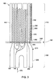
- Figs 3-6 show an example of a turbine bucket 100 as may be described herein.
- the turbine bucket 100 may include an airfoil 110, a platform 120, and a shank portion 130. Similar to that described above, the airfoil 110 extends radially upward from the platform 120 and includes a leading edge 140 and a trailing edge 150.
- the core cavities 160 supply a cooling medium 170 to the components thereof so as to cool the overall turbine bucket 100.
- the cooling medium 170 may be air, steam, and the like from any source.
- a leading edge core cavity 180, a central core cavity 190, and a trailing edge core cavity 200 are shown.
- a number of the core cavities 160 may be used herein. Other components and other configurations may be used.
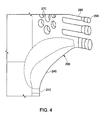
- the trailing edge core cavity 200 may be in the form of a cooling conduit 210.
- the cooling conduit 210 may define a cooling passage 220 extending therethrough for the cooling medium 170.
- the cooling conduit 210 may extend from a cooling input 230 about the shank portion 130 towards the platform 120 and the airfoil 110.
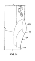
- the cooling conduit 210 may expand at a contoured turn 250.
- the contoured turn 250 thus may have an area of an increased edge radius 260.
- the cooling passage 220 therein likewise expands through the contoured turn 250 so as to reduce the thickness of the material thereabout.
- the contoured turn 250 may have an area of a reduced wall thickness 255.
- the cooling conduit 210 continues through a series of pins 270 or other types of turbulators through the airfoil 110.
- a number of cooling tubes 280 leading to a number of cooling holes 290 may extend towards the trailing edge 150 so as to provide film cooling to the airfoil 110.
- Fig. 5 shows the contoured turn 250 of the cooling conduit 210 about the intersection 240.
- Fig. 6 shows the expanded cooling section 220 about the intersection 240.
- Other components and other configurations also may be used herein.
- the use of the contoured turn 250 in the cooling conduit 210 about the intersection 240 between the airfoil 110 and the platform 120 reduces the stiffness at the intersection 240 via the reduced wall thickness 255.
- the reduced stiffness thus reduces stress therein due to temperature differences between the airfoil 110 and the platform 120.
- the reduced wall thickness 255 about the contoured turn 250 also allows for the larger edge radius 260.
- the larger edge radius 260 also reduces the peak stresses therein. Reducing stress at the intersection 240 should provide increased overall lifetime with reduced maintenance and maintenance costs.
- the reduced wall thickness 255 and increased edge radius 260 may make the overall trailing edge core cavity 200 stronger so as to prevent core breakage during manufacture and thus decreasing overall casting costs. Further, excessive amounts of the cooling medium 170 may not be required herein. The overall impact of thermal expansion to the turbine bucket 100 thus may be reduced.
Description
- The present invention relates generally to gas turbine engines and more particularly relate to a gas turbine engine with a turbine bucket having an airfoil with a core cavity having a contoured turn about a platform so as to reduce stress therein due to thermal expansion.
- Known gas turbine engines generally include rows of circumferentially spaced nozzles and buckets. A turbine bucket generally includes an airfoil having a pressure side and a suction side and extending radially upward from a platform. A hollow shank portion may extend radially downward from the platform and may include a dovetail and the like so as to secure the turbine bucket to a turbine wheel. The platform generally defines an inner boundary for the hot combustion gases flowing through a gas path. As such, the platform may be an area of high stress concentration due to the hot combustion gases and the mechanical loading thereon.
- More specifically, there is often a large amount of thermally induced strain at the intersection of an airfoil and a platform. This thermally induced strain may be due to the temperature differential between the airfoil and the platform. The thermally induced strain may combine with geometric discontinuities in the region so as to create areas of very high stress that may limit component lifetime. To date, these issues have been addressed by attempting to keep geometric discontinuities such as root turns, internal ribs, and the like, away from the intersection. Further, attempts have been made to control the temperature about the intersection. Temperature control, however, generally requires additional cooling flows at the expense of overall engine efficiency. These known cooling arrangements, however, thus may be difficult and expensive to manufacture and may require the use of an excessive amount of air or other types of cooling flows.
-
US 7497661 describes a rotor blade for a gas turbine comprising an airfoil, a platform connecting the airfoil to a blade root and having at least one stiffener extending under the downstream portion of the platform, together with means for cooling the blade by a flow of cooling fluid in ducts formed in the blade and in a cavity formed in the stiffener substantially in register with the trailing edge of the blade, and including outlet orifices facing downstream.EP 1128024 describes a gas turbine moving blade wherein cooling passages are provided for cooling the blade. A recessed portion having smooth curved surface is provided in the platform near the blade fitting portion on the trailing edge side. The fillet of the blade fitting portion on the trailing edge side is formed with a curved surface having a larger curvature than usual. A hub slot below the fillet is formed having a cross sectional area larger than other slots of blade trailing edge. A thermal barrier coating is applied to blade surface. - There is thus a desire for an improved turbine bucket for use with a gas turbine engine. Preferably such a turbine bucket may limit the stresses at the intersection of an airfoil and a platform without excessive manufacturing and operating costs and without excessive cooling medium losses for efficient operation and an extended component lifetime.
- The present invention provides a turbine bucket as defined in the appended claims.
- These and other features and improvement of the present application and the resultant patent will become apparent to one of ordinary skill in the art upon review of the following detailed description when taken in conjunction with the several drawings and the appended claims.
-
Fig. 1 is a schematic diagram of a gas turbine engine with a compressor, a combustor, and a turbine. -
Fig. 2 is a perspective view of a known turbine bucket. -
Fig. 3 is a side plan view of a core body of a turbine bucket as may be described herein. -
Fig. 4 is an expanded view of a trailing edge core cavity as may be described herein. -
Fig. 5 is a sectional view of a portion of the trailing edge core cavity ofFig. 4 . -
Fig. 6 is a further sectional view of a portion of the trailing edge core cavity ofFig. 4 . - Referring now to the drawings, in which like numerals refer to like elements throughout the several views,
Fig. 1 shows a schematic view ofgas turbine engine 10 as may be used herein. Thegas turbine engine 10 may include acompressor 15. Thecompressor 15 compresses an incoming flow ofair 20. Thecompressor 15 delivers the compressed flow ofair 20 to acombustor 25. Thecombustor 25 mixes the compressed flow ofair 20 with a pressurized flow offuel 30 and ignites the mixture to create a flow ofcombustion gases 35. Although only asingle combustor 25 is shown, thegas turbine engine 10 may include any number ofcombustors 25. The flow ofcombustion gases 35 is in turn delivered to aturbine 40. The flow ofcombustion gases 35 drives theturbine 40 so as to produce mechanical work. The mechanical work produced in theturbine 40 drives thecompressor 15 via ashaft 45 and anexternal load 50 such as an electrical generator and the like. - The
gas turbine engine 10 may use natural gas, various types of syngas, and/or other types of fuels. Thegas turbine engine 10 may be any one of a number of different gas turbine engines offered by General Electric Company of Schenectady, New York, including, but not limited to, those such as a 7 or a 9 series heavy duty gas turbine engine and the like. Thegas turbine engine 10 may have different configurations and may use other types of components. Other types of gas turbine engines also may be used herein. Multiple gas turbine engines, other types of turbines, and other types of power generation equipment also may be used herein together. -
Fig. 2 shows an example of aturbine bucket 55 that may be used with theturbine 40. Generally described, theturbine bucket 55 includes anairfoil 60, ashank portion 65, and aplatform 70 disposed between theairfoil 60 and theshank portion 65. Theairfoil 60 generally extends radially upward from theplatform 70 and includes a leadingedge 72 and atrailing edge 74. Theairfoil 60 also may include a concave wall defining apressure side 76 and a convex wall defining asuction side 78. Theplatform 70 may be substantially horizontal and planar. Likewise, theplatform 70 may include atop surface 80, apressure face 82, asuction face 84, aforward face 86, and anaft face 88. Thetop surface 80 of theplatform 70 may be exposed to the flow of thehot combustion gases 35. Theshank portion 65 may extend radially downward from theplatform 70 such that theplatform 70 generally defines an interface between theairfoil 60 and theshank portion 65. Theshank portion 65 may include ashank cavity 90 therein. Theshank portion 65 also may include one ormore angle wings 92 and aroot structure 94 such as a dovetail and the like. Theroot structure 94 may be configured to secure theturbine bucket 55 to theshaft 45. Other components and other configurations may be used herein. - The
turbine bucket 55 may include one ormore cooling circuits 96 extending therethrough for flowing acooling medium 98 such as air from thecompressor 15 or from another source. Thecooling circuits 96 and thecooling medium 98 may circulate at least through portions of theairfoil 60, theshank portion 65, and theplatform 70 in any order, direction, or route. Many different types of cooling circuits and cooling mediums may be used herein. Other components and other configurations also may be used herein. -
Figs 3-6 show an example of a turbine bucket 100 as may be described herein. The turbine bucket 100 may include anairfoil 110, aplatform 120, and ashank portion 130. Similar to that described above, theairfoil 110 extends radially upward from theplatform 120 and includes a leadingedge 140 and atrailing edge 150. Within the turbine bucket 100 there may be a number ofcore cavities 160. Thecore cavities 160 supply acooling medium 170 to the components thereof so as to cool the overall turbine bucket 100. Thecooling medium 170 may be air, steam, and the like from any source. In this example, a leadingedge core cavity 180, acentral core cavity 190, and a trailingedge core cavity 200 are shown. A number of thecore cavities 160 may be used herein. Other components and other configurations may be used. - Generally described, the trailing
edge core cavity 200 may be in the form of acooling conduit 210. Thecooling conduit 210 may define a cooling passage 220 extending therethrough for thecooling medium 170. Thecooling conduit 210 may extend from a coolinginput 230 about theshank portion 130 towards theplatform 120 and theairfoil 110. At about anintersection 240 between theplatform 120 and theairfoil 110, thecooling conduit 210 may expand at acontoured turn 250. Thecontoured turn 250 thus may have an area of an increasededge radius 260. The cooling passage 220 therein likewise expands through the contouredturn 250 so as to reduce the thickness of the material thereabout. Specifically, the contouredturn 250 may have an area of a reducedwall thickness 255. - The
cooling conduit 210 continues through a series ofpins 270 or other types of turbulators through theairfoil 110. Likewise, a number ofcooling tubes 280 leading to a number ofcooling holes 290 may extend towards the trailingedge 150 so as to provide film cooling to theairfoil 110.Fig. 5 shows thecontoured turn 250 of thecooling conduit 210 about theintersection 240. Likewise,Fig. 6 shows the expanded cooling section 220 about theintersection 240. Other components and other configurations also may be used herein. - The use of the contoured
turn 250 in thecooling conduit 210 about theintersection 240 between theairfoil 110 and theplatform 120 reduces the stiffness at theintersection 240 via the reducedwall thickness 255. The reduced stiffness thus reduces stress therein due to temperature differences between theairfoil 110 and theplatform 120. The reducedwall thickness 255 about the contouredturn 250 also allows for thelarger edge radius 260. Thelarger edge radius 260 also reduces the peak stresses therein. Reducing stress at theintersection 240 should provide increased overall lifetime with reduced maintenance and maintenance costs. Moreover, the reducedwall thickness 255 and increasededge radius 260 may make the overall trailingedge core cavity 200 stronger so as to prevent core breakage during manufacture and thus decreasing overall casting costs. Further, excessive amounts of the cooling medium 170 may not be required herein. The overall impact of thermal expansion to the turbine bucket 100 thus may be reduced. - It should be apparent that the foregoing relates only to certain embodiments of the present application and the resultant patent. Numerous changes and modifications may be made herein by one of ordinary skill in the art without departing from the scope of the invention as defined by the following claims.
Claims (10)
- A turbine bucket (100), comprising:a platform (120);an airfoil (110) extending from the platform (120) at an intersection (240) thereof; anda core cavity (160) extending within the platform (120) and the airfoil (110), the core cavity (160) comprises a cooling conduit (210);characterised in thatthe core cavity (160) comprises a contoured turn (250) about the intersection (240), the cooling conduit (210) comprises an area of reduced wall thickness (255) about the contoured turn (250) at the intersection between the airfoil and the platform.
- The turbine bucket of claim 1, wherein the core cavity (160) comprises a trailing edge core cavity (200).
- The turbine bucket of claim 1 or 2, further comprising a plurality of core cavities (160).
- The turbine bucket of any of claims 1 to 3, wherein the core cavity (160) comprises a cooling medium (170) therein.
- The turbine bucket of any preceding claim, wherein the cooling conduit (210) comprises a cooling passage (220) extending therethough.
- The turbine bucket of claim 5, wherein the cooling passage (220) increases in size about the contoured turn (250).
- The turbine bucket of any preceding claim, wherein the cooling conduit (210) comprises an increased edge radius (260) about the contoured turn (250).
- The turbine bucket of any preceding claim, wherein the core cavity (160) comprises a plurality of pins (270) and a plurality of cooling holes (290) downstream of the intersection.
- The turbine bucket of any preceding claim, wherein the core cavity (160) extends from a cooling input (230) to a plurality of cooling holes (290).
- The turbine bucket of any preceding claim, wherein the contoured (250) turn extends in a direction of a trailing edge (150) of the airfoil (120).
Applications Claiming Priority (1)
| Application Number | Priority Date | Filing Date | Title |
|---|---|---|---|
| US13/409,355 US8974182B2 (en) | 2012-03-01 | 2012-03-01 | Turbine bucket with a core cavity having a contoured turn |
Publications (2)
| Publication Number | Publication Date |
|---|---|
| EP2634370A1 EP2634370A1 (en) | 2013-09-04 |
| EP2634370B1 true EP2634370B1 (en) | 2015-11-18 |
Family
ID=47757491
Family Applications (1)
| Application Number | Title | Priority Date | Filing Date |
|---|---|---|---|
| EP13157492.3A Active EP2634370B1 (en) | 2012-03-01 | 2013-03-01 | Turbine bucket with a core cavity having a contoured turn |
Country Status (5)
| Country | Link |
|---|---|
| US (1) | US8974182B2 (en) |
| EP (1) | EP2634370B1 (en) |
| JP (1) | JP6169859B2 (en) |
| CN (1) | CN103291373B (en) |
| RU (1) | RU2013108920A (en) |
Cited By (1)
| Publication number | Priority date | Publication date | Assignee | Title |
|---|---|---|---|---|
| EP4023855A1 (en) * | 2020-12-30 | 2022-07-06 | General Electric Company | Cooled rotor blade |
Families Citing this family (7)
| Publication number | Priority date | Publication date | Assignee | Title |
|---|---|---|---|---|
| EP2868867A1 (en) * | 2013-10-29 | 2015-05-06 | Siemens Aktiengesellschaft | Turbine blade |
| US10012090B2 (en) * | 2014-07-25 | 2018-07-03 | United Technologies Corporation | Airfoil cooling apparatus |
| US11187085B2 (en) | 2017-11-17 | 2021-11-30 | General Electric Company | Turbine bucket with a cooling circuit having an asymmetric root turn |
| US10544686B2 (en) | 2017-11-17 | 2020-01-28 | General Electric Company | Turbine bucket with a cooling circuit having asymmetric root turn |
| US11021961B2 (en) * | 2018-12-05 | 2021-06-01 | General Electric Company | Rotor assembly thermal attenuation structure and system |
| US10815792B2 (en) * | 2019-01-04 | 2020-10-27 | Raytheon Technologies Corporation | Gas turbine engine component with a cooling circuit having a flared base |
| US11629601B2 (en) | 2020-03-31 | 2023-04-18 | General Electric Company | Turbomachine rotor blade with a cooling circuit having an offset rib |
Family Cites Families (30)
| Publication number | Priority date | Publication date | Assignee | Title |
|---|---|---|---|---|
| US5340278A (en) | 1992-11-24 | 1994-08-23 | United Technologies Corporation | Rotor blade with integral platform and a fillet cooling passage |
| US5382135A (en) | 1992-11-24 | 1995-01-17 | United Technologies Corporation | Rotor blade with cooled integral platform |
| US5344283A (en) | 1993-01-21 | 1994-09-06 | United Technologies Corporation | Turbine vane having dedicated inner platform cooling |
| US5848876A (en) | 1997-02-11 | 1998-12-15 | Mitsubishi Heavy Industries, Ltd. | Cooling system for cooling platform of gas turbine moving blade |
| JP3758792B2 (en) | 1997-02-25 | 2006-03-22 | 三菱重工業株式会社 | Gas turbine rotor platform cooling mechanism |
| US5915923A (en) * | 1997-05-22 | 1999-06-29 | Mitsubishi Heavy Industries, Ltd. | Gas turbine moving blade |
| US6190130B1 (en) | 1998-03-03 | 2001-02-20 | Mitsubishi Heavy Industries, Ltd. | Gas turbine moving blade platform |
| US6062817A (en) | 1998-11-06 | 2000-05-16 | General Electric Company | Apparatus and methods for cooling slot step elimination |
| US6390774B1 (en) | 2000-02-02 | 2002-05-21 | General Electric Company | Gas turbine bucket cooling circuit and related process |
| CA2334071C (en) | 2000-02-23 | 2005-05-24 | Mitsubishi Heavy Industries, Ltd. | Gas turbine moving blade |
| US6341939B1 (en) | 2000-07-31 | 2002-01-29 | General Electric Company | Tandem cooling turbine blade |
| US6634858B2 (en) * | 2001-06-11 | 2003-10-21 | Alstom (Switzerland) Ltd | Gas turbine airfoil |
| US6974308B2 (en) * | 2001-11-14 | 2005-12-13 | Honeywell International, Inc. | High effectiveness cooled turbine vane or blade |
| US7147439B2 (en) | 2004-09-15 | 2006-12-12 | General Electric Company | Apparatus and methods for cooling turbine bucket platforms |
| FR2877034B1 (en) | 2004-10-27 | 2009-04-03 | Snecma Moteurs Sa | ROTOR BLADE OF A GAS TURBINE |
| US7168921B2 (en) * | 2004-11-18 | 2007-01-30 | General Electric Company | Cooling system for an airfoil |
| US7255536B2 (en) | 2005-05-23 | 2007-08-14 | United Technologies Corporation | Turbine airfoil platform cooling circuit |
| US7513738B2 (en) | 2006-02-15 | 2009-04-07 | General Electric Company | Methods and apparatus for cooling gas turbine rotor blades |
| US7416391B2 (en) | 2006-02-24 | 2008-08-26 | General Electric Company | Bucket platform cooling circuit and method |
| US7597536B1 (en) | 2006-06-14 | 2009-10-06 | Florida Turbine Technologies, Inc. | Turbine airfoil with de-coupled platform |
| US20080023037A1 (en) * | 2006-07-31 | 2008-01-31 | Lawrence Bernard Kool | Method and apparatus for removing debris from turbine components |
| US7766606B2 (en) | 2006-08-17 | 2010-08-03 | Siemens Energy, Inc. | Turbine airfoil cooling system with platform cooling channels with diffusion slots |
| US7625178B2 (en) * | 2006-08-30 | 2009-12-01 | Honeywell International Inc. | High effectiveness cooled turbine blade |
| US20100034662A1 (en) * | 2006-12-26 | 2010-02-11 | General Electric Company | Cooled airfoil and method for making an airfoil having reduced trail edge slot flow |
| US8047787B1 (en) * | 2007-09-07 | 2011-11-01 | Florida Turbine Technologies, Inc. | Turbine blade with trailing edge root slot |
| US8177507B2 (en) * | 2008-05-14 | 2012-05-15 | United Technologies Corporation | Triangular serpentine cooling channels |
| JP5189406B2 (en) * | 2008-05-14 | 2013-04-24 | 三菱重工業株式会社 | Gas turbine blade and gas turbine provided with the same |
| US8066482B2 (en) | 2008-11-25 | 2011-11-29 | Alstom Technology Ltd. | Shaped cooling holes for reduced stress |
| US8356978B2 (en) | 2009-11-23 | 2013-01-22 | United Technologies Corporation | Turbine airfoil platform cooling core |
| US8523527B2 (en) | 2010-03-10 | 2013-09-03 | General Electric Company | Apparatus for cooling a platform of a turbine component |
-
2012
- 2012-03-01 US US13/409,355 patent/US8974182B2/en active Active
-
2013
- 2013-02-27 JP JP2013036593A patent/JP6169859B2/en active Active
- 2013-02-28 RU RU2013108920/06A patent/RU2013108920A/en not_active Application Discontinuation
- 2013-03-01 EP EP13157492.3A patent/EP2634370B1/en active Active
- 2013-03-01 CN CN201310065320.0A patent/CN103291373B/en active Active
Cited By (1)
| Publication number | Priority date | Publication date | Assignee | Title |
|---|---|---|---|---|
| EP4023855A1 (en) * | 2020-12-30 | 2022-07-06 | General Electric Company | Cooled rotor blade |
Also Published As
| Publication number | Publication date |
|---|---|
| JP6169859B2 (en) | 2017-07-26 |
| US20130230407A1 (en) | 2013-09-05 |
| CN103291373B (en) | 2016-02-24 |
| RU2013108920A (en) | 2014-09-10 |
| CN103291373A (en) | 2013-09-11 |
| JP2013181538A (en) | 2013-09-12 |
| US8974182B2 (en) | 2015-03-10 |
| EP2634370A1 (en) | 2013-09-04 |
Similar Documents
| Publication | Publication Date | Title |
|---|---|---|
| EP2634370B1 (en) | Turbine bucket with a core cavity having a contoured turn | |
| US8721285B2 (en) | Turbine blade with incremental serpentine cooling channels beneath a thermal skin | |
| EP2634369B1 (en) | Turbine buckets and corresponding forming method | |
| US8668453B2 (en) | Cooling system having reduced mass pin fins for components in a gas turbine engine | |
| EP3184742B1 (en) | Turbine airfoil with trailing edge cooling circuit | |
| JP2012102726A (en) | Apparatus, system and method for cooling platform region of turbine rotor blade | |
| EP3415719B1 (en) | Turbomachine blade cooling structure | |
| EP3088674A1 (en) | Rotor blade and corresponding gas turbine | |
| US11927110B2 (en) | Component for a turbine engine with a cooling hole | |
| JP6438662B2 (en) | Cooling passage of turbine blade of gas turbine engine | |
| JP6496539B2 (en) | Method for cooling turbine bucket and turbine bucket of gas turbine engine | |
| CN107035436B (en) | System and method for cooling turbine shroud | |
| EP2971545B1 (en) | Low pressure loss cooled blade | |
| US10001018B2 (en) | Hot gas path component with impingement and pedestal cooling | |
| US10760431B2 (en) | Component for a turbine engine with a cooling hole | |
| US10544686B2 (en) | Turbine bucket with a cooling circuit having asymmetric root turn | |
| EP3412869B1 (en) | Turbomachine rotor blade | |
| EP2634371B1 (en) | Turbine bucket with contoured internal rib | |
| US11187085B2 (en) | Turbine bucket with a cooling circuit having an asymmetric root turn | |
| US20180340428A1 (en) | Turbomachine Rotor Blade Cooling Passage | |
| JP2021071085A (en) | Turbine blade and gas turbine equipped with the same | |
| US11629601B2 (en) | Turbomachine rotor blade with a cooling circuit having an offset rib | |
| EP3203026B1 (en) | Gas turbine blade with pedestal array |
Legal Events
| Date | Code | Title | Description |
|---|---|---|---|
| PUAI | Public reference made under article 153(3) epc to a published international application that has entered the european phase |
Free format text: ORIGINAL CODE: 0009012 |
|
| AK | Designated contracting states |
Kind code of ref document: A1 Designated state(s): AL AT BE BG CH CY CZ DE DK EE ES FI FR GB GR HR HU IE IS IT LI LT LU LV MC MK MT NL NO PL PT RO RS SE SI SK SM TR |
|
| AX | Request for extension of the european patent |
Extension state: BA ME |
|
| 17P | Request for examination filed |
Effective date: 20140304 |
|
| RBV | Designated contracting states (corrected) |
Designated state(s): AL AT BE BG CH CY CZ DE DK EE ES FI FR GB GR HR HU IE IS IT LI LT LU LV MC MK MT NL NO PL PT RO RS SE SI SK SM TR |
|
| 17Q | First examination report despatched |
Effective date: 20141001 |
|
| GRAP | Despatch of communication of intention to grant a patent |
Free format text: ORIGINAL CODE: EPIDOSNIGR1 |
|
| INTG | Intention to grant announced |
Effective date: 20150828 |
|
| GRAS | Grant fee paid |
Free format text: ORIGINAL CODE: EPIDOSNIGR3 |
|
| GRAA | (expected) grant |
Free format text: ORIGINAL CODE: 0009210 |
|
| AK | Designated contracting states |
Kind code of ref document: B1 Designated state(s): AL AT BE BG CH CY CZ DE DK EE ES FI FR GB GR HR HU IE IS IT LI LT LU LV MC MK MT NL NO PL PT RO RS SE SI SK SM TR |
|
| REG | Reference to a national code |
Ref country code: GB Ref legal event code: FG4D |
|
| REG | Reference to a national code |
Ref country code: CH Ref legal event code: EP |
|
| REG | Reference to a national code |
Ref country code: AT Ref legal event code: REF Ref document number: 761691 Country of ref document: AT Kind code of ref document: T Effective date: 20151215 |
|
| REG | Reference to a national code |
Ref country code: IE Ref legal event code: FG4D |
|
| REG | Reference to a national code |
Ref country code: DE Ref legal event code: R096 Ref document number: 602013003801 Country of ref document: DE |
|
| REG | Reference to a national code |
Ref country code: NL Ref legal event code: MP Effective date: 20160218 |
|
| REG | Reference to a national code |
Ref country code: LT Ref legal event code: MG4D |
|
| REG | Reference to a national code |
Ref country code: FR Ref legal event code: PLFP Year of fee payment: 4 |
|
| REG | Reference to a national code |
Ref country code: AT Ref legal event code: MK05 Ref document number: 761691 Country of ref document: AT Kind code of ref document: T Effective date: 20151118 |
|
| PG25 | Lapsed in a contracting state [announced via postgrant information from national office to epo] |
Ref country code: IS Free format text: LAPSE BECAUSE OF FAILURE TO SUBMIT A TRANSLATION OF THE DESCRIPTION OR TO PAY THE FEE WITHIN THE PRESCRIBED TIME-LIMIT Effective date: 20160318 Ref country code: LT Free format text: LAPSE BECAUSE OF FAILURE TO SUBMIT A TRANSLATION OF THE DESCRIPTION OR TO PAY THE FEE WITHIN THE PRESCRIBED TIME-LIMIT Effective date: 20151118 Ref country code: HR Free format text: LAPSE BECAUSE OF FAILURE TO SUBMIT A TRANSLATION OF THE DESCRIPTION OR TO PAY THE FEE WITHIN THE PRESCRIBED TIME-LIMIT Effective date: 20151118 Ref country code: NL Free format text: LAPSE BECAUSE OF FAILURE TO SUBMIT A TRANSLATION OF THE DESCRIPTION OR TO PAY THE FEE WITHIN THE PRESCRIBED TIME-LIMIT Effective date: 20151118 Ref country code: IT Free format text: LAPSE BECAUSE OF FAILURE TO SUBMIT A TRANSLATION OF THE DESCRIPTION OR TO PAY THE FEE WITHIN THE PRESCRIBED TIME-LIMIT Effective date: 20151118 Ref country code: ES Free format text: LAPSE BECAUSE OF FAILURE TO SUBMIT A TRANSLATION OF THE DESCRIPTION OR TO PAY THE FEE WITHIN THE PRESCRIBED TIME-LIMIT Effective date: 20151118 Ref country code: NO Free format text: LAPSE BECAUSE OF FAILURE TO SUBMIT A TRANSLATION OF THE DESCRIPTION OR TO PAY THE FEE WITHIN THE PRESCRIBED TIME-LIMIT Effective date: 20160218 |
|
| PG25 | Lapsed in a contracting state [announced via postgrant information from national office to epo] |
Ref country code: SE Free format text: LAPSE BECAUSE OF FAILURE TO SUBMIT A TRANSLATION OF THE DESCRIPTION OR TO PAY THE FEE WITHIN THE PRESCRIBED TIME-LIMIT Effective date: 20151118 Ref country code: GR Free format text: LAPSE BECAUSE OF FAILURE TO SUBMIT A TRANSLATION OF THE DESCRIPTION OR TO PAY THE FEE WITHIN THE PRESCRIBED TIME-LIMIT Effective date: 20160219 Ref country code: FI Free format text: LAPSE BECAUSE OF FAILURE TO SUBMIT A TRANSLATION OF THE DESCRIPTION OR TO PAY THE FEE WITHIN THE PRESCRIBED TIME-LIMIT Effective date: 20151118 Ref country code: LV Free format text: LAPSE BECAUSE OF FAILURE TO SUBMIT A TRANSLATION OF THE DESCRIPTION OR TO PAY THE FEE WITHIN THE PRESCRIBED TIME-LIMIT Effective date: 20151118 Ref country code: PL Free format text: LAPSE BECAUSE OF FAILURE TO SUBMIT A TRANSLATION OF THE DESCRIPTION OR TO PAY THE FEE WITHIN THE PRESCRIBED TIME-LIMIT Effective date: 20151118 Ref country code: PT Free format text: LAPSE BECAUSE OF FAILURE TO SUBMIT A TRANSLATION OF THE DESCRIPTION OR TO PAY THE FEE WITHIN THE PRESCRIBED TIME-LIMIT Effective date: 20160318 Ref country code: AT Free format text: LAPSE BECAUSE OF FAILURE TO SUBMIT A TRANSLATION OF THE DESCRIPTION OR TO PAY THE FEE WITHIN THE PRESCRIBED TIME-LIMIT Effective date: 20151118 Ref country code: RS Free format text: LAPSE BECAUSE OF FAILURE TO SUBMIT A TRANSLATION OF THE DESCRIPTION OR TO PAY THE FEE WITHIN THE PRESCRIBED TIME-LIMIT Effective date: 20151118 |
|
| PG25 | Lapsed in a contracting state [announced via postgrant information from national office to epo] |
Ref country code: CZ Free format text: LAPSE BECAUSE OF FAILURE TO SUBMIT A TRANSLATION OF THE DESCRIPTION OR TO PAY THE FEE WITHIN THE PRESCRIBED TIME-LIMIT Effective date: 20151118 |
|
| REG | Reference to a national code |
Ref country code: DE Ref legal event code: R097 Ref document number: 602013003801 Country of ref document: DE |
|
| PG25 | Lapsed in a contracting state [announced via postgrant information from national office to epo] |
Ref country code: SM Free format text: LAPSE BECAUSE OF FAILURE TO SUBMIT A TRANSLATION OF THE DESCRIPTION OR TO PAY THE FEE WITHIN THE PRESCRIBED TIME-LIMIT Effective date: 20151118 Ref country code: SK Free format text: LAPSE BECAUSE OF FAILURE TO SUBMIT A TRANSLATION OF THE DESCRIPTION OR TO PAY THE FEE WITHIN THE PRESCRIBED TIME-LIMIT Effective date: 20151118 Ref country code: RO Free format text: LAPSE BECAUSE OF FAILURE TO SUBMIT A TRANSLATION OF THE DESCRIPTION OR TO PAY THE FEE WITHIN THE PRESCRIBED TIME-LIMIT Effective date: 20151118 Ref country code: EE Free format text: LAPSE BECAUSE OF FAILURE TO SUBMIT A TRANSLATION OF THE DESCRIPTION OR TO PAY THE FEE WITHIN THE PRESCRIBED TIME-LIMIT Effective date: 20151118 Ref country code: DK Free format text: LAPSE BECAUSE OF FAILURE TO SUBMIT A TRANSLATION OF THE DESCRIPTION OR TO PAY THE FEE WITHIN THE PRESCRIBED TIME-LIMIT Effective date: 20151118 Ref country code: BE Free format text: LAPSE BECAUSE OF NON-PAYMENT OF DUE FEES Effective date: 20160331 |
|
| PLBE | No opposition filed within time limit |
Free format text: ORIGINAL CODE: 0009261 |
|
| STAA | Information on the status of an ep patent application or granted ep patent |
Free format text: STATUS: NO OPPOSITION FILED WITHIN TIME LIMIT |
|
| 26N | No opposition filed |
Effective date: 20160819 |
|
| PG25 | Lapsed in a contracting state [announced via postgrant information from national office to epo] |
Ref country code: LU Free format text: LAPSE BECAUSE OF FAILURE TO SUBMIT A TRANSLATION OF THE DESCRIPTION OR TO PAY THE FEE WITHIN THE PRESCRIBED TIME-LIMIT Effective date: 20160301 Ref country code: MC Free format text: LAPSE BECAUSE OF FAILURE TO SUBMIT A TRANSLATION OF THE DESCRIPTION OR TO PAY THE FEE WITHIN THE PRESCRIBED TIME-LIMIT Effective date: 20151118 |
|
| PG25 | Lapsed in a contracting state [announced via postgrant information from national office to epo] |
Ref country code: SI Free format text: LAPSE BECAUSE OF FAILURE TO SUBMIT A TRANSLATION OF THE DESCRIPTION OR TO PAY THE FEE WITHIN THE PRESCRIBED TIME-LIMIT Effective date: 20151118 |
|
| REG | Reference to a national code |
Ref country code: IE Ref legal event code: MM4A |
|
| PG25 | Lapsed in a contracting state [announced via postgrant information from national office to epo] |
Ref country code: BE Free format text: LAPSE BECAUSE OF FAILURE TO SUBMIT A TRANSLATION OF THE DESCRIPTION OR TO PAY THE FEE WITHIN THE PRESCRIBED TIME-LIMIT Effective date: 20151118 |
|
| PG25 | Lapsed in a contracting state [announced via postgrant information from national office to epo] |
Ref country code: IE Free format text: LAPSE BECAUSE OF NON-PAYMENT OF DUE FEES Effective date: 20160301 |
|
| REG | Reference to a national code |
Ref country code: FR Ref legal event code: PLFP Year of fee payment: 5 |
|
| PG25 | Lapsed in a contracting state [announced via postgrant information from national office to epo] |
Ref country code: MT Free format text: LAPSE BECAUSE OF FAILURE TO SUBMIT A TRANSLATION OF THE DESCRIPTION OR TO PAY THE FEE WITHIN THE PRESCRIBED TIME-LIMIT Effective date: 20151118 |
|
| GBPC | Gb: european patent ceased through non-payment of renewal fee |
Effective date: 20170301 |
|
| PG25 | Lapsed in a contracting state [announced via postgrant information from national office to epo] |
Ref country code: GB Free format text: LAPSE BECAUSE OF NON-PAYMENT OF DUE FEES Effective date: 20170301 |
|
| REG | Reference to a national code |
Ref country code: FR Ref legal event code: PLFP Year of fee payment: 6 |
|
| PG25 | Lapsed in a contracting state [announced via postgrant information from national office to epo] |
Ref country code: HU Free format text: LAPSE BECAUSE OF FAILURE TO SUBMIT A TRANSLATION OF THE DESCRIPTION OR TO PAY THE FEE WITHIN THE PRESCRIBED TIME-LIMIT; INVALID AB INITIO Effective date: 20130301 Ref country code: CY Free format text: LAPSE BECAUSE OF FAILURE TO SUBMIT A TRANSLATION OF THE DESCRIPTION OR TO PAY THE FEE WITHIN THE PRESCRIBED TIME-LIMIT Effective date: 20151118 |
|
| PG25 | Lapsed in a contracting state [announced via postgrant information from national office to epo] |
Ref country code: MK Free format text: LAPSE BECAUSE OF FAILURE TO SUBMIT A TRANSLATION OF THE DESCRIPTION OR TO PAY THE FEE WITHIN THE PRESCRIBED TIME-LIMIT Effective date: 20151118 Ref country code: TR Free format text: LAPSE BECAUSE OF FAILURE TO SUBMIT A TRANSLATION OF THE DESCRIPTION OR TO PAY THE FEE WITHIN THE PRESCRIBED TIME-LIMIT Effective date: 20151118 Ref country code: MT Free format text: LAPSE BECAUSE OF FAILURE TO SUBMIT A TRANSLATION OF THE DESCRIPTION OR TO PAY THE FEE WITHIN THE PRESCRIBED TIME-LIMIT Effective date: 20160331 |
|
| PG25 | Lapsed in a contracting state [announced via postgrant information from national office to epo] |
Ref country code: BG Free format text: LAPSE BECAUSE OF FAILURE TO SUBMIT A TRANSLATION OF THE DESCRIPTION OR TO PAY THE FEE WITHIN THE PRESCRIBED TIME-LIMIT Effective date: 20151118 |
|
| PG25 | Lapsed in a contracting state [announced via postgrant information from national office to epo] |
Ref country code: AL Free format text: LAPSE BECAUSE OF FAILURE TO SUBMIT A TRANSLATION OF THE DESCRIPTION OR TO PAY THE FEE WITHIN THE PRESCRIBED TIME-LIMIT Effective date: 20151118 |
|
| PGFP | Annual fee paid to national office [announced via postgrant information from national office to epo] |
Ref country code: FR Payment date: 20210219 Year of fee payment: 9 Ref country code: CH Payment date: 20210219 Year of fee payment: 9 |
|
| REG | Reference to a national code |
Ref country code: CH Ref legal event code: PL |
|
| PG25 | Lapsed in a contracting state [announced via postgrant information from national office to epo] |
Ref country code: LI Free format text: LAPSE BECAUSE OF NON-PAYMENT OF DUE FEES Effective date: 20220331 Ref country code: FR Free format text: LAPSE BECAUSE OF NON-PAYMENT OF DUE FEES Effective date: 20220331 Ref country code: CH Free format text: LAPSE BECAUSE OF NON-PAYMENT OF DUE FEES Effective date: 20220331 |
|
| PGFP | Annual fee paid to national office [announced via postgrant information from national office to epo] |
Ref country code: DE Payment date: 20230221 Year of fee payment: 11 |
|
| P01 | Opt-out of the competence of the unified patent court (upc) registered |
Effective date: 20230522 |
|
| REG | Reference to a national code |
Ref country code: DE Ref legal event code: R081 Ref document number: 602013003801 Country of ref document: DE Owner name: GENERAL ELECTRIC TECHNOLOGY GMBH, CH Free format text: FORMER OWNER: GENERAL ELECTRIC COMPANY, SCHENECTADY, NY, US |