EP2045445A2 - Shroud segment, corresponding casting core and method for cooling this segment - Google Patents
Shroud segment, corresponding casting core and method for cooling this segment Download PDFInfo
- Publication number
- EP2045445A2 EP2045445A2 EP08253129A EP08253129A EP2045445A2 EP 2045445 A2 EP2045445 A2 EP 2045445A2 EP 08253129 A EP08253129 A EP 08253129A EP 08253129 A EP08253129 A EP 08253129A EP 2045445 A2 EP2045445 A2 EP 2045445A2
- Authority
- EP
- European Patent Office
- Prior art keywords
- legs
- core
- outlet
- casting
- passageway
- Prior art date
- Legal status (The legal status is an assumption and is not a legal conclusion. Google has not performed a legal analysis and makes no representation as to the accuracy of the status listed.)
- Granted
Links
Images


Classifications
-
- F—MECHANICAL ENGINEERING; LIGHTING; HEATING; WEAPONS; BLASTING
- F01—MACHINES OR ENGINES IN GENERAL; ENGINE PLANTS IN GENERAL; STEAM ENGINES
- F01D—NON-POSITIVE DISPLACEMENT MACHINES OR ENGINES, e.g. STEAM TURBINES
- F01D25/00—Component parts, details, or accessories, not provided for in, or of interest apart from, other groups
- F01D25/24—Casings; Casing parts, e.g. diaphragms, casing fastenings
- F01D25/246—Fastening of diaphragms or stator-rings
-
- B—PERFORMING OPERATIONS; TRANSPORTING
- B22—CASTING; POWDER METALLURGY
- B22C—FOUNDRY MOULDING
- B22C9/00—Moulds or cores; Moulding processes
- B22C9/10—Cores; Manufacture or installation of cores
-
- F—MECHANICAL ENGINEERING; LIGHTING; HEATING; WEAPONS; BLASTING
- F01—MACHINES OR ENGINES IN GENERAL; ENGINE PLANTS IN GENERAL; STEAM ENGINES
- F01D—NON-POSITIVE DISPLACEMENT MACHINES OR ENGINES, e.g. STEAM TURBINES
- F01D11/00—Preventing or minimising internal leakage of working-fluid, e.g. between stages
- F01D11/08—Preventing or minimising internal leakage of working-fluid, e.g. between stages for sealing space between rotor blade tips and stator
- F01D11/10—Preventing or minimising internal leakage of working-fluid, e.g. between stages for sealing space between rotor blade tips and stator using sealing fluid, e.g. steam
-
- F—MECHANICAL ENGINEERING; LIGHTING; HEATING; WEAPONS; BLASTING
- F05—INDEXING SCHEMES RELATING TO ENGINES OR PUMPS IN VARIOUS SUBCLASSES OF CLASSES F01-F04
- F05D—INDEXING SCHEME FOR ASPECTS RELATING TO NON-POSITIVE-DISPLACEMENT MACHINES OR ENGINES, GAS-TURBINES OR JET-PROPULSION PLANTS
- F05D2230/00—Manufacture
- F05D2230/20—Manufacture essentially without removing material
- F05D2230/21—Manufacture essentially without removing material by casting
-
- F—MECHANICAL ENGINEERING; LIGHTING; HEATING; WEAPONS; BLASTING
- F05—INDEXING SCHEMES RELATING TO ENGINES OR PUMPS IN VARIOUS SUBCLASSES OF CLASSES F01-F04
- F05D—INDEXING SCHEME FOR ASPECTS RELATING TO NON-POSITIVE-DISPLACEMENT MACHINES OR ENGINES, GAS-TURBINES OR JET-PROPULSION PLANTS
- F05D2240/00—Components
- F05D2240/10—Stators
- F05D2240/11—Shroud seal segments
Definitions
- This invention relates to gas turbine engines. More particularly, the invention relates to casting of cooled shrouds or blade outer air seals (BOAS).
- BOAS blade outer air seals
- BOAS segments may be internally cooled by bleed air.
- bleed air there may be an upstream-to-downstream array of circumferentially-extending cooling passageway legs within the BOAS. Cooling air may be fed into the passageway legs from the outboard (OD) side of the BOAS (e.g., via one or more inlet ports at ends of the passageway legs). The cooling air may exit the legs through outlet ports in the circumferential ends (matefaces) of the BOAS so as to be vented into the adjacent inter-segment region. The vented air may, for example, help cool adjacent BOAS segments and purge the gap to prevent gas ingestion.
- the BOAS segments may be cast via an investment casting process.
- a ceramic casting core is used to form the passageway legs.
- the core has legs corresponding to the passageway legs.
- the core legs extend between first and second end portions of the core.
- the core may be placed in a die. Wax may be molded in the die over the core legs to form a pattern.
- the pattern may be shelled (e.g., a stuccoing process to form a ceramic shell).
- the wax may be removed from the shell.
- Metal may be cast in the shell over the core.
- the shell and core may be destructively removed. After core removal, the core legs leave the passageway legs in the casting.
- the as-cast passageway legs are open at both circumferential ends of the raw BOAS casting. At least some of the end openings are closed via plug welding, braze pins, or other means. Air inlets to the passageway legs may be drilled from the OD side of the casting.
- the core has first and second end portions and a plurality of legs. Of these legs, first legs each have: a proximal end joining the first end portion; a main body portion; and a free distal portion. Second legs each have: a proximal end joining the second end portion; a main body portion; and a free distal portion.
- first legs each have: a proximal end joining the first end portion; a main body portion; and a free distal portion.
- the distal portions of the first and second legs may project transverse to the main body portion.
- the core may be formed of refractory metal sheetstock.
- the core may have a ceramic coating.
- the proximal portions may each comprise a reduced cross-section neck.
- At least one third leg may connect the first end portion to the second end portion.
- the at least one third leg may include first and second perimeter or edge legs.
- a plurality of connector branches may connect adjacent pairs of the legs.
- the connector branches may have minimum cross-sections smaller than adjacent cross-sections of the connected legs.
- the core may be embedded in a shell and a casting cast partially over the core.
- the first and second end portions of the core may project from the casting into the shell.
- the first and second leg distal portions may project into the shell or may terminate in the casting.
- the core may be manufactured by cutting from a refractory metal sheet. After the cutting, the first and second leg distal portions may be bent transverse to associated main body portions of those legs.
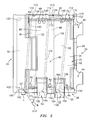
- FIG. 1 shows blade outer air seal (BOAS) 20.
- the BOAS has a main body portion 22 having a leading/upstream/ forward end 24 and a trailing/downstream/aft end 26.
- the body has first and second circumferential ends or matefaces 28 and 30.
- the body has an inboard (ID) face 32 and an OD face 34.
- To mount the BOAS to a support structure 40 FIG. 3 ; e.g., a portion of the engine case), the exemplary BOAS has a plurality of mounting hooks.
- the exemplary BOAS has a single central forward mounting hook 42 having a forwardly-projecting distal portion recessed aft of the forward end 24.
- the exemplary BOAS has a pair of first and second aft hooks 44 and 46 having rearwardly-projecting distal portions protruding aft beyond the aft end 26.
- a circumferential ring array of a plurality of the BOAS 22 may encircle an associated blade stage of a gas turbine engine.
- the assembled ID faces 32 thus locally bound an outboard extreme of the core flowpath 48 ( FIG. 3 ).
- the BOAS 22 may have features for interlocking the array. Exemplary features include finger and shiplap joints.
- the exemplary BOAS 22 has a pair of fore and aft fingers 50 and 52 projecting from the first circumferential end 28 and which, when assembled, lie radially outboard of the second circumferential end 30 of the adjacent BOAS.
- the BOAS may be air-cooled.
- bleed air may be directed to a chamber 56 ( FIG. 3 ) immediately outboard of the face 34.
- the bleed air may be directed through ports 60, 62, 64, 66, 68, 70, and 72 ( FIG. 2 ) to an internal cooling passageway network 80.
- the configuration of the exemplary BOAS 20 is based upon the configuration shown in EP 1886745 . Nevertheless, the principles discussed below may be applied to other BOAS configurations (e.g., in a reengineering situation).
- the exemplary network includes a plurality of circumferentially-extending legs 82, 84, 86, 88, 90, and 92.
- the network may have a plurality of outlets/exits.
- Exemplary outlets may include outlets along the circumferential ends 28 and 30.
- outlets 100, 101, 102, 104, and 105 are formed along the first circumferential end 28 and outlets 110, 112, 113, 114, and 115 are formed along the second circumferential end 30.
- adjacent legs may be interconnected by interconnecting passageways 120, 122, 124, 126, and 128.
- the inlet 66 feeds the leg 82 near a closed end 130 of the leg 82.
- the air flows down the leg 82 to the outlets 100 and 101 at ends of outlet passageways 160 and 161.
- the exemplary passageways 160 and 161 are formed as twin neck regions or branches at the other end 132 of the leg 82.
- the inlet 60 feeds the leg 84 near a closed end 134.
- the outlet 110 is at an end of an outlet passageway 170 formed as a neck region at the other end 136.
- the inlets 68 and 70 feed the leg 86 near a closed end 138.
- the outlet 102 is formed at the other end 140.
- the inlet 62 feeds the leg 88 near a closed end 142.
- the dual outlets 112 and 113 are at ends of outlet passageways 172 and 173 at the other end 144.
- the inlet 72 feeds the leg 90 near a closed end 146.
- the dual outlets 104 and 105 are at ends of outlet passageways 164 and 165.
- the exemplary passageways 164 and 165 are formed as neck regions at the other end 148.
- the inlet 64 feeds the leg 92 near a closed end 150.
- the dual outlets 114 and 115 are at ends of outlet passageways 164 and 165.
- the exemplary passageways 164 and 165 are formed as neck regions at the other end 152.
- FIG. 5 shows a refractory metal core (RMC) 200 for casting the passageway legs.
- the core 200 may be cut from a metallic sheet (e.g., of a refractory metal).
- An exemplary cutting is laser cutting. Alternative cutting may be via a stamping operation.
- the exemplary RMC 200 has first and second end portions 202 and 204.
- First and second perimeter legs 206 and 208 extend between and join the end portions 202 and 204 to form a frame-like structure. Between the perimeter legs 206 and 208, there is an array of legs 210, 212, 214, 216, 218, and 220 which respectively cast the passageway legs 82, 84, 86, 88, 90, and 92.
- each of the RMC legs has a proximal end joining the adjacent one of the end portions 202 and 204 and a free distal end spaced apart from the other end portion.
- a main body of the leg extends between the proximal and distal ends.
- the core leg distal ends 230, 232, 234, 236, 238, and 240 respectively cast the passageway leg closed ends 130, 134, 138, 142, 146, and 150.
- the core leg proximal ends have branches 242, 243; 244; 246; 248, 249, 250, 251; and 252, 253 which respectively cast the outlets 100, 101; 110; 102; 112, 113; 104, 105; and 114, 115.
- FIG. 5 further shows a first bend line 520 and a second bend line 522.
- the exemplary bend lines 520 and 522 intersect the associated leg proximal end branches so that the bending of the RMC at the bend lines provides a corresponding radial aiming of the branches and thus of the ends of the corresponding outlet passageways.
- FIG. 6 shows the outlet passageway 165 having a distal portion 291 radially departing relative to a proximal portion 292 in-plane with the associated leg 90.
- the distal portion 291 extends to the outlet 105 departing slightly radially inward by an angle ⁇ o .
- Such inward radial aiming/orientation may help resist ingestion of gas from the hot gas path 524 into the inter-segment space 526.
- exemplary values of ⁇ o are 5-30°.
- the prior art plug welding step can be eliminated or reduced.
- the lack of local connection of the core leg free distal ends to the adjacent core end portion 202 or 204 may compromise structural integrity.
- the RMC 200 has connecting portions 260, 262, 264, 266, and 268 connecting the main body portions of the adjacent legs. These connecting portions end up casting the passageways 120, 122, 124, 126, and 128, respectively.
- the connecting portions may advantageously be positioned at locations along the adjacent legs wherein air pressure in the cast passageway legs will be equal. This may minimize cross-flow and reduce losses. However, such location may provide less-than-desirable RMC strengthening. Thus, the connecting portions may be shifted (e.g., pushed circumferentially outward) relative to the optimal pressure balancing locations.
- FIG. 5 also schematically shows a shell 280 having an internal surface 282.
- the shell 280 is formed over a wax pattern containing the RMC 200 for casting the BOAS.
- the inlets 60, 62, 64, 66, 68, 70, and 72 may be drilled (e.g., as part of a machining process applied to the raw casting).
- paired/dual outlets may more evenly distribute the cooling and may provide better overall cooling for a given mass flow rate of cooling air. For example, this may be seen in the outlets 100, 101. These may be compared with a single central baseline outlet (e.g., longitudinally centered near the end 132 of the leg 82). The outlet 100 is offset longitudinally downstream by a length L. This brings the outlet 101 closer to the adjacent end 134 of the adjacent downstream leg 84 to provide enhanced local cooling along the end 28.
- the centerline 510 of the passageway of outlet 101 is oriented off longitudinal by an angle ⁇ (e.g., and off circumferential by 90° minus ⁇ ).
- ⁇ is 90° +/- 45°.
- exemplary ⁇ is 10-45° off-normal.
- This downstream angling may facilitate a greater offset L than would otherwise be possible, locating the outlet 101 downstream/aft of the downstream extremity of the leg 82 at the end 132.
- the outlet exit angles may be chosen to use the exit air momentum as purge air to counter any tendencies for local gas ingestion between segments (as noted previously).
- RMC with free distal leg portions may avoid or reduce the need for plug welding.
- Use of an RMC relative to a ceramic core may permit the casting of finer passageways. For example, core thickness and passageway height may be reduced relative to those of a baseline ceramic core and its cast passageways.
- the use of RMC may allow outlets to be significantly narrower. The narrowing facilitates the splitting a single outlet into two or more discrete outlets for better local control over the cooling and purge air. Exemplary RMC thicknesses are less than 1.25mm, more narrowly, 0.5-1.0mm.
- the RMC may also readily be provided with features (e.g., stamped/embossed or laser etched recesses) for casting internal trip strips or other surface enhancements.
- radially constricting one to all of the interconnecting passageways e.g., 120, 122, 124, 126, and 128) to have a smaller thickness (radial height) than characteristic thickness (e.g., mean, median, or modal) of the adjacent passageway legs.
- This may be provided by a corresponding thinning of the RMC connecting portions (e.g., 260, 262, 264, 266, and 268).
- Exemplary thinning may be from one or both RMC faces and may be performed as part of the main cutting of the RMC or later.
- legs may involve forming one or more of the legs with outlets at both ends of such leg.
- flow throughout the ports relatively near the inlet ports may be facilitated by walls and/or posts within the associated leg between the inlet port and such outlet port (e.g., as is shown in EP 1905958 ).
Landscapes
- Engineering & Computer Science (AREA)
- Mechanical Engineering (AREA)
- General Engineering & Computer Science (AREA)
- Turbine Rotor Nozzle Sealing (AREA)
- Molds, Cores, And Manufacturing Methods Thereof (AREA)
Abstract
Description
- This invention relates to gas turbine engines. More particularly, the invention relates to casting of cooled shrouds or blade outer air seals (BOAS).
- BOAS segments may be internally cooled by bleed air. For example, there may be an upstream-to-downstream array of circumferentially-extending cooling passageway legs within the BOAS. Cooling air may be fed into the passageway legs from the outboard (OD) side of the BOAS (e.g., via one or more inlet ports at ends of the passageway legs). The cooling air may exit the legs through outlet ports in the circumferential ends (matefaces) of the BOAS so as to be vented into the adjacent inter-segment region. The vented air may, for example, help cool adjacent BOAS segments and purge the gap to prevent gas ingestion.
- The BOAS segments may be cast via an investment casting process. In an exemplary casting process, a ceramic casting core is used to form the passageway legs. The core has legs corresponding to the passageway legs. The core legs extend between first and second end portions of the core. The core may be placed in a die. Wax may be molded in the die over the core legs to form a pattern. The pattern may be shelled (e.g., a stuccoing process to form a ceramic shell). The wax may be removed from the shell. Metal may be cast in the shell over the core. The shell and core may be destructively removed. After core removal, the core legs leave the passageway legs in the casting. The as-cast passageway legs are open at both circumferential ends of the raw BOAS casting. At least some of the end openings are closed via plug welding, braze pins, or other means. Air inlets to the passageway legs may be drilled from the OD side of the casting.
- One aspect of the disclosure involves a blade outer air seal (BOAS) casting core. The core has first and second end portions and a plurality of legs. Of these legs, first legs each have: a proximal end joining the first end portion; a main body portion; and a free distal portion. Second legs each have: a proximal end joining the second end portion; a main body portion; and a free distal portion.
- In various implementations, the distal portions of the first and second legs may project transverse to the main body portion. The core may be formed of refractory metal sheetstock. The core may have a ceramic coating. The proximal portions may each comprise a reduced cross-section neck. At least one third leg may connect the first end portion to the second end portion. The at least one third leg may include first and second perimeter or edge legs. A plurality of connector branches may connect adjacent pairs of the legs. The connector branches may have minimum cross-sections smaller than adjacent cross-sections of the connected legs.
- The core may be embedded in a shell and a casting cast partially over the core. The first and second end portions of the core may project from the casting into the shell. The first and second leg distal portions may project into the shell or may terminate in the casting.
- The core may be manufactured by cutting from a refractory metal sheet. After the cutting, the first and second leg distal portions may be bent transverse to associated main body portions of those legs.
- The details of one or more embodiments are set forth in the accompanying drawings and the description below. Other features, objects, and advantages will be apparent from the description and drawings, and from the claims.
-
-
FIG. 1 is a view of a blade outer airseal (BOAS). -
FIG. 2 is an OD/top view of the BOAS ofFIG. 1 . -
FIG. 3 is a first circumferential end view of the BOAS ofFIG. 1 . -
FIG. 4 is a second circumferential end view of the BOAS ofFIG. 1 . -
FIG. 5 is a plan view of a refractory metal core (RMC) for casting a cooling passageway network of the BOAS ofFIG. 1 . -
FIG. 6 is a sectional view of a BOAS assembly. - Like reference numbers and designations in the various drawings indicate like elements.
-
FIG. 1 shows blade outer air seal (BOAS) 20. The BOAS has amain body portion 22 having a leading/upstream/forward end 24 and a trailing/downstream/aft end 26. The body has first and second circumferential ends ormatefaces face 32 and anOD face 34. To mount the BOAS to a support structure 40 (FIG. 3 ; e.g., a portion of the engine case), the exemplary BOAS has a plurality of mounting hooks. The exemplary BOAS has a single centralforward mounting hook 42 having a forwardly-projecting distal portion recessed aft of theforward end 24. The exemplary BOAS has a pair of first andsecond aft hooks aft end 26. - A circumferential ring array of a plurality of the
BOAS 22 may encircle an associated blade stage of a gas turbine engine. The assembled ID faces 32 thus locally bound an outboard extreme of the core flowpath 48 (FIG. 3 ). The BOAS 22 may have features for interlocking the array. Exemplary features include finger and shiplap joints. Theexemplary BOAS 22 has a pair of fore andaft fingers circumferential end 28 and which, when assembled, lie radially outboard of the secondcircumferential end 30 of the adjacent BOAS. - The BOAS may be air-cooled. For example, bleed air may be directed to a chamber 56 (
FIG. 3 ) immediately outboard of theface 34. The bleed air may be directed throughports FIG. 2 ) to an internalcooling passageway network 80. The configuration of theexemplary BOAS 20 is based upon the configuration shown inEP 1886745 . Nevertheless, the principles discussed below may be applied to other BOAS configurations (e.g., in a reengineering situation). The exemplary network includes a plurality of circumferentially-extendinglegs exemplary BOAS 22,outlets circumferential end 28 andoutlets circumferential end 30. As is discussed in further detail below, adjacent legs may be interconnected by interconnectingpassageways - In operation, the inlet 66 feeds the
leg 82 near aclosed end 130 of theleg 82. The air flows down theleg 82 to theoutlets outlet passageways exemplary passageways other end 132 of theleg 82. Similarly, theinlet 60 feeds theleg 84 near aclosed end 134. Theoutlet 110 is at an end of anoutlet passageway 170 formed as a neck region at the other end 136. Theinlets 68 and 70 feed theleg 86 near a closed end 138. Theoutlet 102 is formed at theother end 140. Theinlet 62 feeds theleg 88 near aclosed end 142. Thedual outlets outlet passageways 172 and 173 at theother end 144. Theinlet 72 feeds theleg 90 near aclosed end 146. Thedual outlets outlet passageways exemplary passageways other end 148. Theinlet 64 feeds theleg 92 near aclosed end 150. Thedual outlets outlet passageways exemplary passageways other end 152. -
FIG. 5 shows a refractory metal core (RMC) 200 for casting the passageway legs. Thecore 200 may be cut from a metallic sheet (e.g., of a refractory metal). An exemplary cutting is laser cutting. Alternative cutting may be via a stamping operation. Theexemplary RMC 200 has first andsecond end portions second perimeter legs end portions perimeter legs legs passageway legs end portions branches outlets -
FIG. 5 further shows a first bend line 520 and a second bend line 522. The exemplary bend lines 520 and 522 intersect the associated leg proximal end branches so that the bending of the RMC at the bend lines provides a corresponding radial aiming of the branches and thus of the ends of the corresponding outlet passageways. For example,FIG. 6 shows theoutlet passageway 165 having adistal portion 291 radially departing relative to aproximal portion 292 in-plane with the associatedleg 90. Thedistal portion 291 extends to theoutlet 105 departing slightly radially inward by an angle θo. Such inward radial aiming/orientation may help resist ingestion of gas from thehot gas path 524 into theinter-segment space 526. For non-zero θo, exemplary values of θo are 5-30°. - As in
EP 1886745 , by using free distal ends of the RMC legs to cast closed passageway leg ends, the prior art plug welding step can be eliminated or reduced. However, the lack of local connection of the core leg free distal ends to the adjacentcore end portion RMC 200 has connectingportions passageways - From an airflow perspective, the connecting portions may advantageously be positioned at locations along the adjacent legs wherein air pressure in the cast passageway legs will be equal. This may minimize cross-flow and reduce losses. However, such location may provide less-than-desirable RMC strengthening. Thus, the connecting portions may be shifted (e.g., pushed circumferentially outward) relative to the optimal pressure balancing locations.
-
FIG. 5 also schematically shows ashell 280 having aninternal surface 282. Theshell 280 is formed over a wax pattern containing theRMC 200 for casting the BOAS. After dewaxing, casting, and deshelling/decoring, theinlets - There may be one or more advantages to using the
exemplary RMC 200 or modifications thereof. The use of paired/dual outlets (e.g., 100, 101; 104, 105; 112, 113; and 114, 115) may more evenly distribute the cooling and may provide better overall cooling for a given mass flow rate of cooling air. For example, this may be seen in theoutlets end 132 of the leg 82). Theoutlet 100 is offset longitudinally downstream by a length L. This brings theoutlet 101 closer to theadjacent end 134 of the adjacentdownstream leg 84 to provide enhanced local cooling along theend 28. Thecenterline 510 of the passageway ofoutlet 101 is oriented off longitudinal by an angle θ (e.g., and off circumferential by 90° minus θ). Exemplary θ is 90° +/- 45°. Where θ is off-normal, exemplary θ is 10-45° off-normal. This downstream angling may facilitate a greater offset L than would otherwise be possible, locating theoutlet 101 downstream/aft of the downstream extremity of theleg 82 at theend 132. In addition to simply offsetting the outlets, the outlet exit angles (including off-radial components) may be chosen to use the exit air momentum as purge air to counter any tendencies for local gas ingestion between segments (as noted previously). - Additionally, as in
EP 1886745 , use of the RMC with free distal leg portions may avoid or reduce the need for plug welding. Use of an RMC relative to a ceramic core may permit the casting of finer passageways. For example, core thickness and passageway height may be reduced relative to those of a baseline ceramic core and its cast passageways. In addition, the use of RMC may allow outlets to be significantly narrower. The narrowing facilitates the splitting a single outlet into two or more discrete outlets for better local control over the cooling and purge air. Exemplary RMC thicknesses are less than 1.25mm, more narrowly, 0.5-1.0mm. The RMC may also readily be provided with features (e.g., stamped/embossed or laser etched recesses) for casting internal trip strips or other surface enhancements. - Further variations may involve radially constricting one to all of the interconnecting passageways (e.g., 120, 122, 124, 126, and 128) to have a smaller thickness (radial height) than characteristic thickness (e.g., mean, median, or modal) of the adjacent passageway legs. This may be provided by a corresponding thinning of the RMC connecting portions (e.g., 260, 262, 264, 266, and 268). Exemplary thinning may be from one or both RMC faces and may be performed as part of the main cutting of the RMC or later.
- Further variations may involve forming one or more of the legs with outlets at both ends of such leg. For example, flow throughout the ports relatively near the inlet ports may be facilitated by walls and/or posts within the associated leg between the inlet port and such outlet port (e.g., as is shown in
EP 1905958 ). - One or more embodiments have been described. Nevertheless, it will be understood that various modifications may be made. For example, when implemented in the reengineering of a baseline BOAS, or using existing manufacturing techniques and equipment, details of the baseline BOAS or existing techniques or equipment may influence details of any particular implementation.
Claims (15)
- A blade outer airseal segment (20) comprising:a forward longitudinal end (24);an aft longitudinal end (26);a first circumferential end (28);a second circumferential end (30);an inboard face (32);a plurality of circumferential passageway legs (82-92) having outboard inlet ports (60-72) and including:wherein:a plurality of first said legs (84, 88, 92) each having at least one outlet (110-115) along the second end; anda plurality of second said legs (82, 86, 90) each having at least one outlet (100-105) along the first end,at least one of the first legs or second legs includes a pair of outlet passageways (100, 101; 112, 113) longitudinally diverging.
- The blade outer airseal of claim 1 wherein:said pair comprises a first said outlet passageway (114) longitudinally diverging forward and a second said outlet passageway (101) longitudinally diverging aftward.
- The blade outer airseal of claim 1 or 2 wherein:said at least one of the first legs or second legs includes at least one of the first legs and at least one of the second legs.
- The blade outer airseal of claim 1, 2 or 3 wherein:at least one outlet passageway of the pair of outlet passageways is angled radially inward, preferably by 5-30°.
- The blade outer airseal of claim 4 wherein:both of the outlet passageways of said pair of outlet passageways are angled radially inward.
- A casting core (200) comprising:first and second end portions (202, 204); anda plurality of legs (210-220) including:wherein:a plurality of first legs (210, 214, 218), each having:an end joining the first end portion; anda main body; and a plurality of second legs (212, 216, 220), each having:an end joining the second end portion;a main body; andsaid end of at least one of the first legs or second legs comprises a pair of diverging branches (242, 243).
- The casting core of claim 6 wherein:the branches are bent along a longitudinal bend line, preferably by 5-30° transverse to the main body portion.
- The core of claim 6 or 7 wherein:the core is formed of refractory metal sheetstock, preferably with a thickness of 0.5-1.0 mm.
- The core of claim 6, 7 or 8 wherein:the core has a ceramic coating.
- The core of claim 6, 7, 8 or 9, further comprising:at least one third leg (206, 208) connecting the first end portion to the second end portion.
- The core of claim 10 wherein:said at least one third leg includes first and second perimeter legs (206, 208).
- The core of any of claims 6 to 11 further comprising:a plurality of connector branches (260-268) connecting adjacent pairs of said legs and having minimum cross-section smaller than adjacent cross-sections of the connected legs.
- The core of claim 12 wherein:the connector branches have smaller thickness than characteristic thickness of the connected legs.
- A raw casting, shell, and core combination comprising:a shell;a core as claimed in any of claims 6 to 13; anda casting partially over said core, said ends projecting from the casting into the shell.
- A method for cooling a blade outer airseal segment (20), the segment comprising:a forward longitudinal end (24);an aft longitudinal end (26);a first circumferential end (28);a second circumferential end (30);an inboard face (32);a plurality of circumferential passageway legs (82-90) having outboard inlet ports (60-72) and including:a plurality of first said legs (84, 88, 92) each having at least one outlet (110-115) along the second end; anda plurality of second said legs (82, 86, 90) each having at least one outlet (100-105) along the first end,the method comprising:introducing cooling air to the first legs and the second legs;passing the cooling air in the first legs to the at least one outlet thereof;passing the cooling air in the second legs to the at least one outlet thereof;discharging the air from the at least one outlet of at least one of the first legs or second legs to branch and longitudinally diverge.
Applications Claiming Priority (1)
| Application Number | Priority Date | Filing Date | Title |
|---|---|---|---|
| US11/865,229 US7874792B2 (en) | 2007-10-01 | 2007-10-01 | Blade outer air seals, cores, and manufacture methods |
Publications (3)
| Publication Number | Publication Date |
|---|---|
| EP2045445A2 true EP2045445A2 (en) | 2009-04-08 |
| EP2045445A3 EP2045445A3 (en) | 2012-04-04 |
| EP2045445B1 EP2045445B1 (en) | 2016-03-09 |
Family
ID=40010769
Family Applications (1)
| Application Number | Title | Priority Date | Filing Date |
|---|---|---|---|
| EP08253129.4A Active EP2045445B1 (en) | 2007-10-01 | 2008-09-25 | Shroud segment, corresponding casting core and method for cooling this segment |
Country Status (2)
| Country | Link |
|---|---|
| US (1) | US7874792B2 (en) |
| EP (1) | EP2045445B1 (en) |
Cited By (4)
| Publication number | Priority date | Publication date | Assignee | Title |
|---|---|---|---|---|
| CH704140A1 (en) * | 2010-11-29 | 2012-05-31 | Alstom Technology Ltd | Blade assembly for a rotating flow machine. |
| EP2963250A1 (en) * | 2014-06-30 | 2016-01-06 | Rolls-Royce Corporation | Coating for isolating metallic components from composite components |
| EP3006669A1 (en) * | 2014-09-02 | 2016-04-13 | United Technologies Corporation | Actively cooled blade outer air seal |
| EP2511482A3 (en) * | 2011-04-13 | 2017-11-15 | General Electric Company | Turbine shroud segment cooling system and method |
Families Citing this family (21)
| Publication number | Priority date | Publication date | Assignee | Title |
|---|---|---|---|---|
| US8740551B2 (en) * | 2009-08-18 | 2014-06-03 | Pratt & Whitney Canada Corp. | Blade outer air seal cooling |
| US8651497B2 (en) | 2011-06-17 | 2014-02-18 | United Technologies Corporation | Winged W-seal |
| US9238970B2 (en) | 2011-09-19 | 2016-01-19 | United Technologies Corporation | Blade outer air seal assembly leading edge core configuration |
| US9316109B2 (en) * | 2012-04-10 | 2016-04-19 | General Electric Company | Turbine shroud assembly and method of forming |
| US20130340966A1 (en) | 2012-06-21 | 2013-12-26 | United Technologies Corporation | Blade outer air seal hybrid casting core |
| US9803491B2 (en) | 2012-12-31 | 2017-10-31 | United Technologies Corporation | Blade outer air seal having shiplap structure |
| US10006367B2 (en) * | 2013-03-15 | 2018-06-26 | United Technologies Corporation | Self-opening cooling passages for a gas turbine engine |
| US9797262B2 (en) | 2013-07-26 | 2017-10-24 | United Technologies Corporation | Split damped outer shroud for gas turbine engine stator arrays |
| EP3030754B1 (en) * | 2013-08-06 | 2018-11-14 | United Technologies Corporation | Boas with radial load feature |
| EP3042045A4 (en) * | 2013-09-06 | 2017-06-14 | United Technologies Corporation | Canted boas intersegment geometry |
| SG11201601724TA (en) | 2013-09-11 | 2016-04-28 | Energy Absorption System | Crash attenuator |
| EP3105422B1 (en) * | 2014-02-14 | 2020-06-10 | United Technologies Corporation | Blade outer air seal fin cooling assembly and method |
| US10316683B2 (en) | 2014-04-16 | 2019-06-11 | United Technologies Corporation | Gas turbine engine blade outer air seal thermal control system |
| US10329934B2 (en) | 2014-12-15 | 2019-06-25 | United Technologies Corporation | Reversible flow blade outer air seal |
| US9926799B2 (en) | 2015-10-12 | 2018-03-27 | United Technologies Corporation | Gas turbine engine components, blade outer air seal assemblies, and blade outer air seal segments thereof |
| US10815827B2 (en) | 2016-01-25 | 2020-10-27 | Raytheon Technologies Corporation | Variable thickness core for gas turbine engine component |
| US11262142B2 (en) | 2016-04-26 | 2022-03-01 | Northrop Grumman Systems Corporation | Heat exchangers, weld configurations for heat exchangers and related systems and methods |
| US11193386B2 (en) | 2016-05-18 | 2021-12-07 | Raytheon Technologies Corporation | Shaped cooling passages for turbine blade outer air seal |
| GB201720121D0 (en) * | 2017-12-04 | 2018-01-17 | Siemens Ag | Heatshield for a gas turbine engine |
| PE20221234A1 (en) | 2019-05-15 | 2022-08-12 | Trinity Highway Products Llc | SHOCK ATTENUATOR WITH RELEASE PLATE HINGE ASSEMBLY, RELEASE PLATE HINGE ASSEMBLY AND METHOD FOR USE THEREOF |
| US11274566B2 (en) * | 2019-08-27 | 2022-03-15 | Raytheon Technologies Corporation | Axial retention geometry for a turbine engine blade outer air seal |
Citations (5)
| Publication number | Priority date | Publication date | Assignee | Title |
|---|---|---|---|---|
| EP0516322A1 (en) | 1991-05-20 | 1992-12-02 | General Electric Company | Shroud cooling assembly for gas turbine engine |
| US6139257A (en) | 1998-03-23 | 2000-10-31 | General Electric Company | Shroud cooling assembly for gas turbine engine |
| EP1176285A2 (en) | 2000-07-27 | 2002-01-30 | General Electric Company | Shroud cooling segment and assembly |
| EP1586743A1 (en) | 2004-04-15 | 2005-10-19 | Snecma | Turbine shroud |
| EP1905951A2 (en) | 2006-09-20 | 2008-04-02 | United Technologies Corporation | Structual members in a pedestal array |
Family Cites Families (5)
| Publication number | Priority date | Publication date | Assignee | Title |
|---|---|---|---|---|
| US5486090A (en) * | 1994-03-30 | 1996-01-23 | United Technologies Corporation | Turbine shroud segment with serpentine cooling channels |
| US5538393A (en) * | 1995-01-31 | 1996-07-23 | United Technologies Corporation | Turbine shroud segment with serpentine cooling channels having a bend passage |
| US5609469A (en) * | 1995-11-22 | 1997-03-11 | United Technologies Corporation | Rotor assembly shroud |
| US7686068B2 (en) * | 2006-08-10 | 2010-03-30 | United Technologies Corporation | Blade outer air seal cores and manufacture methods |
| US7650926B2 (en) * | 2006-09-28 | 2010-01-26 | United Technologies Corporation | Blade outer air seals, cores, and manufacture methods |
-
2007
- 2007-10-01 US US11/865,229 patent/US7874792B2/en active Active
-
2008
- 2008-09-25 EP EP08253129.4A patent/EP2045445B1/en active Active
Patent Citations (5)
| Publication number | Priority date | Publication date | Assignee | Title |
|---|---|---|---|---|
| EP0516322A1 (en) | 1991-05-20 | 1992-12-02 | General Electric Company | Shroud cooling assembly for gas turbine engine |
| US6139257A (en) | 1998-03-23 | 2000-10-31 | General Electric Company | Shroud cooling assembly for gas turbine engine |
| EP1176285A2 (en) | 2000-07-27 | 2002-01-30 | General Electric Company | Shroud cooling segment and assembly |
| EP1586743A1 (en) | 2004-04-15 | 2005-10-19 | Snecma | Turbine shroud |
| EP1905951A2 (en) | 2006-09-20 | 2008-04-02 | United Technologies Corporation | Structual members in a pedestal array |
Cited By (6)
| Publication number | Priority date | Publication date | Assignee | Title |
|---|---|---|---|---|
| CH704140A1 (en) * | 2010-11-29 | 2012-05-31 | Alstom Technology Ltd | Blade assembly for a rotating flow machine. |
| EP2511482A3 (en) * | 2011-04-13 | 2017-11-15 | General Electric Company | Turbine shroud segment cooling system and method |
| EP2963250A1 (en) * | 2014-06-30 | 2016-01-06 | Rolls-Royce Corporation | Coating for isolating metallic components from composite components |
| US9920656B2 (en) | 2014-06-30 | 2018-03-20 | Rolls-Royce Corporation | Coating for isolating metallic components from composite components |
| EP3006669A1 (en) * | 2014-09-02 | 2016-04-13 | United Technologies Corporation | Actively cooled blade outer air seal |
| US10221767B2 (en) | 2014-09-02 | 2019-03-05 | United Technologies Corporation | Actively cooled blade outer air seal |
Also Published As
| Publication number | Publication date |
|---|---|
| US20090087306A1 (en) | 2009-04-02 |
| EP2045445A3 (en) | 2012-04-04 |
| US7874792B2 (en) | 2011-01-25 |
| EP2045445B1 (en) | 2016-03-09 |
Similar Documents
| Publication | Publication Date | Title |
|---|---|---|
| EP2045445B1 (en) | Shroud segment, corresponding casting core and method for cooling this segment | |
| EP1886745B1 (en) | Blade outer air seal cores and manufacture methods | |
| US7650926B2 (en) | Blade outer air seals, cores, and manufacture methods | |
| EP1772209B1 (en) | Investment casting pattern manufacture | |
| EP1813775B1 (en) | Film cooled component of gas turbine engine | |
| US7625172B2 (en) | Vane platform cooling | |
| EP1952911B1 (en) | Turbine blade, casting core and method | |
| US7744347B2 (en) | Peripheral microcircuit serpentine cooling for turbine airfoils | |
| EP2000232B1 (en) | Cooled wall with thickness control | |
| US10781716B2 (en) | Blade outer air seal cooling scheme | |
| EP1923152B1 (en) | Trubine blade casting method | |
| EP3821996B1 (en) | Core assembly including studded spacer |
Legal Events
| Date | Code | Title | Description |
|---|---|---|---|
| PUAI | Public reference made under article 153(3) epc to a published international application that has entered the european phase |
Free format text: ORIGINAL CODE: 0009012 |
|
| AK | Designated contracting states |
Kind code of ref document: A2 Designated state(s): AT BE BG CH CY CZ DE DK EE ES FI FR GB GR HR HU IE IS IT LI LT LU LV MC MT NL NO PL PT RO SE SI SK TR |
|
| AX | Request for extension of the european patent |
Extension state: AL BA MK RS |
|
| REG | Reference to a national code |
Ref country code: DE Ref legal event code: R079 Ref document number: 602008042672 Country of ref document: DE Free format text: PREVIOUS MAIN CLASS: F01D0011240000 Ipc: F01D0025240000 |
|
| PUAL | Search report despatched |
Free format text: ORIGINAL CODE: 0009013 |
|
| AK | Designated contracting states |
Kind code of ref document: A3 Designated state(s): AT BE BG CH CY CZ DE DK EE ES FI FR GB GR HR HU IE IS IT LI LT LU LV MC MT NL NO PL PT RO SE SI SK TR |
|
| AX | Request for extension of the european patent |
Extension state: AL BA MK RS |
|
| RIC1 | Information provided on ipc code assigned before grant |
Ipc: F01D 25/24 20060101AFI20120224BHEP Ipc: F01D 11/10 20060101ALI20120224BHEP |
|
| 17P | Request for examination filed |
Effective date: 20121004 |
|
| AKX | Designation fees paid |
Designated state(s): DE GB |
|
| 17Q | First examination report despatched |
Effective date: 20121121 |
|
| GRAP | Despatch of communication of intention to grant a patent |
Free format text: ORIGINAL CODE: EPIDOSNIGR1 |
|
| INTG | Intention to grant announced |
Effective date: 20150908 |
|
| GRAS | Grant fee paid |
Free format text: ORIGINAL CODE: EPIDOSNIGR3 |
|
| GRAA | (expected) grant |
Free format text: ORIGINAL CODE: 0009210 |
|
| AK | Designated contracting states |
Kind code of ref document: B1 Designated state(s): DE GB |
|
| REG | Reference to a national code |
Ref country code: GB Ref legal event code: FG4D |
|
| REG | Reference to a national code |
Ref country code: DE Ref legal event code: R096 Ref document number: 602008042672 Country of ref document: DE |
|
| RAP2 | Party data changed (patent owner data changed or rights of a patent transferred) |
Owner name: UNITED TECHNOLOGIES CORPORATION |
|
| REG | Reference to a national code |
Ref country code: DE Ref legal event code: R097 Ref document number: 602008042672 Country of ref document: DE |
|
| PLBE | No opposition filed within time limit |
Free format text: ORIGINAL CODE: 0009261 |
|
| STAA | Information on the status of an ep patent application or granted ep patent |
Free format text: STATUS: NO OPPOSITION FILED WITHIN TIME LIMIT |
|
| 26N | No opposition filed |
Effective date: 20161212 |
|
| REG | Reference to a national code |
Ref country code: DE Ref legal event code: R082 Ref document number: 602008042672 Country of ref document: DE Representative=s name: SCHMITT-NILSON SCHRAUD WAIBEL WOHLFROM PATENTA, DE |
|
| REG | Reference to a national code |
Ref country code: DE Ref legal event code: R082 Ref document number: 602008042672 Country of ref document: DE Representative=s name: SCHMITT-NILSON SCHRAUD WAIBEL WOHLFROM PATENTA, DE Ref country code: DE Ref legal event code: R081 Ref document number: 602008042672 Country of ref document: DE Owner name: UNITED TECHNOLOGIES CORP. (N.D.GES.D. STAATES , US Free format text: FORMER OWNER: UNITED TECHNOLOGIES CORPORATION, HARTFORD, CONN., US |
|
| REG | Reference to a national code |
Ref country code: DE Ref legal event code: R081 Ref document number: 602008042672 Country of ref document: DE Owner name: RAYTHEON TECHNOLOGIES CORPORATION (N.D.GES.D.S, US Free format text: FORMER OWNER: UNITED TECHNOLOGIES CORP. (N.D.GES.D. STAATES DELAWARE), FARMINGTON, CONN., US Ref country code: DE Ref legal event code: R081 Ref document number: 602008042672 Country of ref document: DE Owner name: RTX CORPORATION (N.D.GES.D. STAATES DELAWARE),, US Free format text: FORMER OWNER: UNITED TECHNOLOGIES CORP. (N.D.GES.D. STAATES DELAWARE), FARMINGTON, CONN., US |
|
| P01 | Opt-out of the competence of the unified patent court (upc) registered |
Effective date: 20230519 |
|
| PGFP | Annual fee paid to national office [announced via postgrant information from national office to epo] |
Ref country code: DE Payment date: 20250820 Year of fee payment: 18 |
|
| PGFP | Annual fee paid to national office [announced via postgrant information from national office to epo] |
Ref country code: GB Payment date: 20250820 Year of fee payment: 18 |
|
| REG | Reference to a national code |
Ref country code: DE Ref legal event code: R081 Ref document number: 602008042672 Country of ref document: DE Owner name: RTX CORPORATION (N.D.GES.D. STAATES DELAWARE),, US Free format text: FORMER OWNER: RAYTHEON TECHNOLOGIES CORPORATION (N.D.GES.D.STAATES DELAWARE), ARLINGTON, VA, US |