JP7109901B2 - Transition manifold for cooling channel connections of cooling structures - Google Patents
Transition manifold for cooling channel connections of cooling structures Download PDFInfo
- Publication number
- JP7109901B2 JP7109901B2 JP2017204128A JP2017204128A JP7109901B2 JP 7109901 B2 JP7109901 B2 JP 7109901B2 JP 2017204128 A JP2017204128 A JP 2017204128A JP 2017204128 A JP2017204128 A JP 2017204128A JP 7109901 B2 JP7109901 B2 JP 7109901B2
- Authority
- JP
- Japan
- Prior art keywords
- cooling
- cavity
- turbine
- cooling structure
- exhaust
- Prior art date
- Legal status (The legal status is an assumption and is not a legal conclusion. Google has not performed a legal analysis and makes no representation as to the accuracy of the status listed.)
- Active
Links
- 238000001816 cooling Methods 0.000 title claims description 100
- 230000007704 transition Effects 0.000 title claims description 48
- 239000007789 gas Substances 0.000 claims description 53
- 239000012530 fluid Substances 0.000 claims description 28
- 238000004891 communication Methods 0.000 claims description 23
- 238000002485 combustion reaction Methods 0.000 claims description 12
- 239000000567 combustion gas Substances 0.000 claims description 6
- 230000002093 peripheral effect Effects 0.000 claims description 6
- 238000000034 method Methods 0.000 claims description 5
- 238000004519 manufacturing process Methods 0.000 description 12
- 239000002826 coolant Substances 0.000 description 6
- 239000000463 material Substances 0.000 description 4
- 238000011144 upstream manufacturing Methods 0.000 description 4
- 239000012809 cooling fluid Substances 0.000 description 3
- 239000000654 additive Substances 0.000 description 2
- 230000000996 additive effect Effects 0.000 description 2
- 238000005266 casting Methods 0.000 description 2
- 239000011248 coating agent Substances 0.000 description 2
- 238000000576 coating method Methods 0.000 description 2
- 210000003041 ligament Anatomy 0.000 description 2
- 239000007788 liquid Substances 0.000 description 2
- 239000000203 mixture Substances 0.000 description 2
- 238000012986 modification Methods 0.000 description 2
- 230000004048 modification Effects 0.000 description 2
- 230000000712 assembly Effects 0.000 description 1
- 238000000429 assembly Methods 0.000 description 1
- 239000011230 binding agent Substances 0.000 description 1
- 230000015572 biosynthetic process Effects 0.000 description 1
- 230000003247 decreasing effect Effects 0.000 description 1
- 230000008021 deposition Effects 0.000 description 1
- 238000010586 diagram Methods 0.000 description 1
- 238000007599 discharging Methods 0.000 description 1
- 230000005611 electricity Effects 0.000 description 1
- 238000005516 engineering process Methods 0.000 description 1
- 230000003628 erosive effect Effects 0.000 description 1
- 238000001125 extrusion Methods 0.000 description 1
- 239000000446 fuel Substances 0.000 description 1
- 230000006870 function Effects 0.000 description 1
- 230000003434 inspiratory effect Effects 0.000 description 1
- 238000003475 lamination Methods 0.000 description 1
- 238000003754 machining Methods 0.000 description 1
- 239000002184 metal Substances 0.000 description 1
- 238000003801 milling Methods 0.000 description 1
- 239000000843 powder Substances 0.000 description 1
- 238000007639 printing Methods 0.000 description 1
- 238000004904 shortening Methods 0.000 description 1
- 230000003685 thermal hair damage Effects 0.000 description 1
Images


Classifications
-
- F—MECHANICAL ENGINEERING; LIGHTING; HEATING; WEAPONS; BLASTING
- F01—MACHINES OR ENGINES IN GENERAL; ENGINE PLANTS IN GENERAL; STEAM ENGINES
- F01D—NON-POSITIVE DISPLACEMENT MACHINES OR ENGINES, e.g. STEAM TURBINES
- F01D5/00—Blades; Blade-carrying members; Heating, heat-insulating, cooling or antivibration means on the blades or the members
- F01D5/12—Blades
- F01D5/14—Form or construction
- F01D5/18—Hollow blades, i.e. blades with cooling or heating channels or cavities; Heating, heat-insulating or cooling means on blades
-
- F—MECHANICAL ENGINEERING; LIGHTING; HEATING; WEAPONS; BLASTING
- F02—COMBUSTION ENGINES; HOT-GAS OR COMBUSTION-PRODUCT ENGINE PLANTS
- F02C—GAS-TURBINE PLANTS; AIR INTAKES FOR JET-PROPULSION PLANTS; CONTROLLING FUEL SUPPLY IN AIR-BREATHING JET-PROPULSION PLANTS
- F02C7/00—Features, components parts, details or accessories, not provided for in, or of interest apart form groups F02C1/00 - F02C6/00; Air intakes for jet-propulsion plants
- F02C7/12—Cooling of plants
-
- F—MECHANICAL ENGINEERING; LIGHTING; HEATING; WEAPONS; BLASTING
- F01—MACHINES OR ENGINES IN GENERAL; ENGINE PLANTS IN GENERAL; STEAM ENGINES
- F01D—NON-POSITIVE DISPLACEMENT MACHINES OR ENGINES, e.g. STEAM TURBINES
- F01D11/00—Preventing or minimising internal leakage of working-fluid, e.g. between stages
- F01D11/08—Preventing or minimising internal leakage of working-fluid, e.g. between stages for sealing space between rotor blade tips and stator
-
- F—MECHANICAL ENGINEERING; LIGHTING; HEATING; WEAPONS; BLASTING
- F01—MACHINES OR ENGINES IN GENERAL; ENGINE PLANTS IN GENERAL; STEAM ENGINES
- F01D—NON-POSITIVE DISPLACEMENT MACHINES OR ENGINES, e.g. STEAM TURBINES
- F01D25/00—Component parts, details, or accessories, not provided for in, or of interest apart from, other groups
- F01D25/08—Cooling; Heating; Heat-insulation
- F01D25/12—Cooling
-
- F—MECHANICAL ENGINEERING; LIGHTING; HEATING; WEAPONS; BLASTING
- F01—MACHINES OR ENGINES IN GENERAL; ENGINE PLANTS IN GENERAL; STEAM ENGINES
- F01D—NON-POSITIVE DISPLACEMENT MACHINES OR ENGINES, e.g. STEAM TURBINES
- F01D9/00—Stators
- F01D9/02—Nozzles; Nozzle boxes; Stator blades; Guide conduits, e.g. individual nozzles
-
- F—MECHANICAL ENGINEERING; LIGHTING; HEATING; WEAPONS; BLASTING
- F02—COMBUSTION ENGINES; HOT-GAS OR COMBUSTION-PRODUCT ENGINE PLANTS
- F02C—GAS-TURBINE PLANTS; AIR INTAKES FOR JET-PROPULSION PLANTS; CONTROLLING FUEL SUPPLY IN AIR-BREATHING JET-PROPULSION PLANTS
- F02C3/00—Gas-turbine plants characterised by the use of combustion products as the working fluid
- F02C3/04—Gas-turbine plants characterised by the use of combustion products as the working fluid having a turbine driving a compressor
-
- F—MECHANICAL ENGINEERING; LIGHTING; HEATING; WEAPONS; BLASTING
- F05—INDEXING SCHEMES RELATING TO ENGINES OR PUMPS IN VARIOUS SUBCLASSES OF CLASSES F01-F04
- F05D—INDEXING SCHEME FOR ASPECTS RELATING TO NON-POSITIVE-DISPLACEMENT MACHINES OR ENGINES, GAS-TURBINES OR JET-PROPULSION PLANTS
- F05D2220/00—Application
- F05D2220/30—Application in turbines
- F05D2220/32—Application in turbines in gas turbines
-
- F—MECHANICAL ENGINEERING; LIGHTING; HEATING; WEAPONS; BLASTING
- F05—INDEXING SCHEMES RELATING TO ENGINES OR PUMPS IN VARIOUS SUBCLASSES OF CLASSES F01-F04
- F05D—INDEXING SCHEME FOR ASPECTS RELATING TO NON-POSITIVE-DISPLACEMENT MACHINES OR ENGINES, GAS-TURBINES OR JET-PROPULSION PLANTS
- F05D2240/00—Components
- F05D2240/10—Stators
- F05D2240/11—Shroud seal segments
-
- F—MECHANICAL ENGINEERING; LIGHTING; HEATING; WEAPONS; BLASTING
- F05—INDEXING SCHEMES RELATING TO ENGINES OR PUMPS IN VARIOUS SUBCLASSES OF CLASSES F01-F04
- F05D—INDEXING SCHEME FOR ASPECTS RELATING TO NON-POSITIVE-DISPLACEMENT MACHINES OR ENGINES, GAS-TURBINES OR JET-PROPULSION PLANTS
- F05D2240/00—Components
- F05D2240/80—Platforms for stationary or moving blades
- F05D2240/81—Cooled platforms
-
- F—MECHANICAL ENGINEERING; LIGHTING; HEATING; WEAPONS; BLASTING
- F05—INDEXING SCHEMES RELATING TO ENGINES OR PUMPS IN VARIOUS SUBCLASSES OF CLASSES F01-F04
- F05D—INDEXING SCHEME FOR ASPECTS RELATING TO NON-POSITIVE-DISPLACEMENT MACHINES OR ENGINES, GAS-TURBINES OR JET-PROPULSION PLANTS
- F05D2260/00—Function
- F05D2260/20—Heat transfer, e.g. cooling
- F05D2260/202—Heat transfer, e.g. cooling by film cooling
-
- F—MECHANICAL ENGINEERING; LIGHTING; HEATING; WEAPONS; BLASTING
- F05—INDEXING SCHEMES RELATING TO ENGINES OR PUMPS IN VARIOUS SUBCLASSES OF CLASSES F01-F04
- F05D—INDEXING SCHEME FOR ASPECTS RELATING TO NON-POSITIVE-DISPLACEMENT MACHINES OR ENGINES, GAS-TURBINES OR JET-PROPULSION PLANTS
- F05D2260/00—Function
- F05D2260/20—Heat transfer, e.g. cooling
- F05D2260/204—Heat transfer, e.g. cooling by the use of microcircuits
-
- F—MECHANICAL ENGINEERING; LIGHTING; HEATING; WEAPONS; BLASTING
- F05—INDEXING SCHEMES RELATING TO ENGINES OR PUMPS IN VARIOUS SUBCLASSES OF CLASSES F01-F04
- F05D—INDEXING SCHEME FOR ASPECTS RELATING TO NON-POSITIVE-DISPLACEMENT MACHINES OR ENGINES, GAS-TURBINES OR JET-PROPULSION PLANTS
- F05D2260/00—Function
- F05D2260/20—Heat transfer, e.g. cooling
- F05D2260/221—Improvement of heat transfer
- F05D2260/2214—Improvement of heat transfer by increasing the heat transfer surface
Description
本開示は、一般に、ガスタービンの冷却構造に関し、より具体的には、構造の縁部冷却を最大限にして制御する、チャネルの吸気および排気接続部を冷却するための移行マニホールドに関する。 TRANSITION MANIFOLDS FOR COOLING CHANNEL INTAKE AND EXHAUST CONNECTIONS TECHNICAL FIELD This disclosure relates generally to cooling structures for gas turbines, and more specifically to transition manifolds for cooling inlet and exhaust connections of channels that maximize and control edge cooling of the structures.
大型の強力な産業用ガスタービンエンジンでは、燃焼器内で発生した高温ガス流をタービンに通して機械的仕事を生じる。タービンは、次第に減少する温度で高温ガス流と反応するステータベーンおよびロータブレードの1つまたは複数の列または段を含む。より高い温度のガス流をタービンに通すことによって、タービンの効率、したがってエンジンの効率を高めることができる。ただし、タービンの入口温度は、タービン、特に第1段のベーンおよびブレードの材料特性、ならびにこれらの第1段の翼形部の冷却能力の大きさに制限される。 In large, powerful industrial gas turbine engines, a hot gas stream generated in a combustor is passed through a turbine to produce mechanical work. The turbine includes one or more rows or stages of stator vanes and rotor blades that react with the hot gas stream at decreasing temperatures. By passing a higher temperature gas stream through the turbine, the efficiency of the turbine, and thus the efficiency of the engine, can be increased. However, the inlet temperature of the turbine is limited by the material properties of the turbine, especially the first stage vanes and blades, and the amount of cooling capacity of these first stage airfoils.
第1段のロータブレードおよびステータベーンは、最も高いガス流温度に曝され、ガス流がタービン段を通過するにつれて温度が徐々に低下する。冷却空気を内部冷却通路に通し、冷却空気をフィルム冷却孔に排出して、冷却空気のブランケット層を提供して、冷却表面を高温ガス流から保護することによって、第1段および第2段の翼形部(ブレードおよびベーン)ならびにシュラウドおよび他の構造体は冷却されなければならない。 The rotor blades and stator vanes of the first stage are exposed to the highest gas flow temperatures and gradually decrease in temperature as the gas flow passes through the turbine stages. First and second stages are cooled by passing cooling air through internal cooling passages and discharging cooling air into film cooling holes to provide a blanket layer of cooling air to protect the cooling surfaces from hot gas flow. Airfoils (blades and vanes) as well as shrouds and other structures must be cooled.
タービンロータブレードは、ブレード先端とのギャップを形成するシュラウドによって形成された冷却表面内で回転する。シュラウドは、リングキャリア内に固定された多数のセグメントから形成される。ギャップを通過する高温ガス流漏れは、タービン効率を低下させるだけでなく、シュラウド上にホットスポットを形成して、寿命を縮めるような浸食または他の熱による損傷をもたらす。 Turbine rotor blades rotate within a cooling surface formed by a shroud that forms a gap with the blade tips. The shroud is formed from multiple segments secured within the ring carrier. Hot gas flow leakage through the gap not only reduces turbine efficiency, but also creates hot spots on the shroud leading to life-shortening erosion or other thermal damage.
マイクロチャネルの吸気端および排気端の現行の製造プロセスでは、端部を各端部が役立つ正しいチャネルと整列させるために高精度の機械加工が必要とされる。これらの製造上の制限は、冷却空気流の計量のための吸気端および排気端のサイズ、断面積および流れ面積の柔軟性を妨げる。現行の許容スタッキングでは、マイクロチャネルを測定することはできない。 Current manufacturing processes for the inlet and outlet ends of microchannels require high precision machining to align the ends with the correct channels that each end serves. These manufacturing limitations prevent flexibility in the size, cross-sectional area and flow area of the inlet and outlet ends for metering cooling airflow. Microchannels cannot be measured with the current allowable stacking.
本開示の態様および利点は、以下の説明に一部が記載されるか、またはその説明から明らかにすることができ、あるいは本開示の実施を通じて理解することができる。 Aspects and advantages of the disclosure are set forth in part in, or may be apparent from, the description that follows, or may be learned through practice of the disclosure.
ガスタービンエンジンの冷却構造の一実施形態は、前縁、後縁、第1の側部、第2の側部、およびキャビティを備えた本体を有する。冷却空気マイクロチャネルの第1セットは、キャビティから延び、第1の側部に沿って配置される。冷却空気マイクロチャネルの第2セットは、キャビティから延び、第2の側部に沿って配置される。冷却空気マイクロチャネルの各セットは、隣接するマイクロチャネルと流体連通し、また、吸気端、排気端、およびそれらの組み合わせのうちの少なくとも1つと流体連通している少なくとも1つの移行マニホールドを有する。 One embodiment of a cooling structure for a gas turbine engine has a body with a leading edge, a trailing edge, a first side, a second side, and a cavity. A first set of cooling air microchannels extends from the cavity and is disposed along the first side. A second set of cooling air microchannels extends from the cavity and is disposed along the second side. Each set of cooling air microchannels has at least one transition manifold in fluid communication with adjacent microchannels and with at least one of an intake end, an exhaust end, and combinations thereof.
別の実施形態は、圧縮機セクションと、圧縮機の下流に位置する燃焼セクション内の複数の燃焼器と、燃焼セクションの下流に位置するタービンセクションとを有するガスタービン内で実施される、上記の冷却構造を有する。 Another embodiment is implemented in a gas turbine having a compressor section, multiple combustors in a combustion section downstream from the compressor, and a turbine section downstream from the combustion section. It has a cooling structure.
本開示の、これらおよび他の特徴、態様、および利点は、以下の説明および添付の特許請求の範囲を参照することによってより良く理解されよう。添付の図面は、本明細書に組み込まれて、本明細書の一部を構成し、本開示の実施形態を例示し、説明と共に本開示の原理を説明するのに役立つ。 These and other features, aspects, and advantages of the present disclosure will become better understood with reference to the following description and appended claims. The accompanying drawings, which are incorporated in and constitute a part of this specification, illustrate embodiments of the disclosure and, together with the description, serve to explain the principles of the disclosure.
最良の形態を含み、当業者を対象とする、完全かつ実施可能な程度の開示が本明細書に記載され、以下の添付の図面を参照する。 A complete and enabling disclosure, including the best mode, directed to those skilled in the art is set forth herein and reference is made to the following accompanying drawings.
本明細書および図面における符号の反復使用は、本開示の同じまたは類似の特徴もしくは要素を表すことを意図している。 Repeat use of symbols in the present specification and drawings is intended to represent same or analogous features or elements of the present disclosure.
以下、本発明の本実施形態について詳しく説明するが、その1つまたは複数の例が、添付の図面に示されている。詳細な説明では、図面中の特徴を参照するために数値および文字による記号が使用されている。図面および説明の中で同じまたは類似の記号は、本発明の同じまたは類似の部品を参照するために使用されている。本明細書で使用する場合、用語「第1の」、「第2の」、および「第3の」は、ある構成要素を別の構成要素から区別するために交換可能に使用されることができ、個々の構成要素の位置または重要性を示すことを意図するものではない。用語「上流」および「下流」は、流体経路における流体の流れに対する相対的な方向を指す。例えば、「上流」は流体が流れてくる方向を指し、「下流」は流体が流れていく方向を指す。用語「半径方向に」は、特定の構成要素の軸方向中心線に実質的に垂直な相対方向を指し、用語「軸方向に」は、特定の構成要素の軸方向中心線に実質的に平行な相対方向を指す。「断面積」は、本明細書では、冷却空気または他の流体が流れる通路の平面領域として規定される。本明細書で使用する「マイクロチャネル」は、約800ミクロン(μm)~約3ミリメートル(mm)の水力直径を有する小さなチャネルであり、高温表面領域の温度を許容範囲内に維持するために、冷却構造の高温表面の近くに配置されて、冷却構造に冷却流体(例えば、圧縮機冷却空気)を輸送し、熱を交換する。グループを記述するために本明細書で使用する「セット」という用語は、「少なくとも1つの」マイクロチャネルまたは「少なくとも1つの」要素として規定される。 Reference will now be made in detail to the present embodiments of the invention, one or more examples of which are illustrated in the accompanying drawings. The detailed description uses numerical and letter symbols to refer to features in the drawings. The same or similar symbols have been used in the drawings and description to refer to the same or similar parts of the invention. As used herein, the terms "first," "second," and "third" may be used interchangeably to distinguish one component from another. and is not intended to indicate the location or importance of individual components. The terms "upstream" and "downstream" refer to directions relative to fluid flow in a fluid path. For example, "upstream" refers to the direction from which the fluid flows, and "downstream" refers to the direction from which the fluid flows. The term "radially" refers to relative directions substantially perpendicular to the axial centerline of the particular component, and the term "axially" refers to directions substantially parallel to the axial centerline of the particular component. relative direction. "Cross-sectional area" is defined herein as the planar area of a passage through which cooling air or other fluid flows. As used herein, a "microchannel" is a small channel having a hydraulic diameter of about 800 microns (μm) to about 3 millimeters (mm), in order to maintain the temperature of the hot surface area within an acceptable range, It is positioned near the hot surface of the cooling structure to transport cooling fluid (eg, compressor cooling air) to the cooling structure and exchange heat. The term "set" as used herein to describe a group is defined as "at least one" microchannel or "at least one" element.
各例は、本発明の限定としてではなく、本発明の例示として提示される。実際、本開示の範囲または趣旨を逸脱せずに、修正および変更が本発明において可能であることは、当業者にとって明らかであろう。例えば、一実施形態の一部として図示または説明された特徴を別の実施形態で使用し、さらに別の実施形態を得ることができる。よって、本発明は、添付の請求項およびそれらの均等物の範囲内にある、そのような修正形態および変形形態をカバーすることを意図している。本発明の例示的な実施形態は、説明の目的で産業用ガスタービンに関して一般的に説明されるが、当業者であれば、本発明の実施形態を任意のターボ機械に適用することができ、特許請求の範囲に具体的に列挙しない限り、産業用ガスタービンに限定されないことを容易に理解するであろう。産業用、舶用、または陸上用のガスタービンが本明細書に示され説明されているが、本明細書に示され説明される本開示は、特許請求の範囲に特に明記されない限り、陸上用および/または産業用、および/または舶用のガスタービンに限定されない。例えば、本明細書に記載される開示は、限定されるものではないが、航空機転用タービンまたは舶用ガスタービンならびに航空機エンジンタービンを含む任意のタイプのタービンに使用され得る。 Each example is presented by way of illustration of the invention, not as a limitation of the invention. Indeed, it will be apparent to those skilled in the art that modifications and variations are possible in the present invention without departing from the scope or spirit of this disclosure. For instance, features illustrated or described as part of one embodiment can be used on another embodiment to yield a still further embodiment. Thus, it is intended that the present invention cover such modifications and variations as come within the scope of the appended claims and their equivalents. Although exemplary embodiments of the present invention are generally described with respect to industrial gas turbines for purposes of explanation, those skilled in the art will be able to apply embodiments of the present invention to any turbomachine, It will be readily understood that the invention is not limited to industrial gas turbines unless specifically recited in the claims. Although industrial, marine, or land-based gas turbines may be shown and described herein, the disclosure as shown and described herein may be used for both land-based and land-based gas turbines, unless otherwise specified in the claims. /or is not limited to industrial and/or marine gas turbines. For example, the disclosure provided herein may be used for any type of turbine including, but not limited to, aeroderivative or marine gas turbines as well as aircraft engine turbines.
本明細書の冷却構造は、構造の完全性を保つために、強制冷却空気源との直接接触を必要とする任意の構造として規定される。これらの構造は、タービンシュラウド、ノズル、ブレード、およびタービンの任意の他の高温ガス経路構成要素の部分を含むことができる。 A cooling structure herein is defined as any structure that requires direct contact with a source of forced cooling air to preserve the integrity of the structure. These structures may include portions of turbine shrouds, nozzles, blades, and any other hot gas path components of the turbine.
本明細書に記載の移行マニホールドは、改良された見通し線および製造のための目標領域を提供するために、マイクロチャネルの吸気端および排気端の近くに配置される。移行マニホールドを、約0.2ミリメートル(mm)~約3ミリメートル(mm)の範囲の水力直径を有する従来のチャネル、ミニチャネル、マイクロチャネルなどを含む任意のサイズの冷却通路に適用することができる。移行マニホールドは、流量計量を可能にし、マイクロチャネルを通る冷却空気流を制御することができるように、サイズを変えることもできる。一般的に半径方向の多様なマニホールド深さは、他のマイクロチャネルまたは他の本体機構の周りの流れの方向転換を可能にし、そうでなければ、可能な交差を避けるために見通し線および十分な材料リガメントを必要とする。 The transition manifolds described herein are placed near the inlet and outlet ends of microchannels to provide improved line of sight and target areas for manufacturing. The transition manifold can be applied to cooling passages of any size, including conventional channels, mini-channels, micro-channels, etc., with hydraulic diameters ranging from about 0.2 millimeters (mm) to about 3 millimeters (mm). . The transition manifold can also be sized to allow flow metering and control of cooling airflow through the microchannels. The variable manifold depths, generally radial, allow for redirection of flow around other microchannels or other body features, otherwise line of sight and sufficient depth to avoid possible crossovers. Requires material ligaments.
隣接するマイクロチャネルより大きな断面積および冷却空気流面積を有する移行マニホールドは、吸気端および排気端を製造するためのより大きな目標を提供し、既存の製造上の限界を克服するためにより大きな計量孔を受け入れることができる。吸気端および排気端の計量領域は、チャネル寸法の製造ばらつきの影響を受けにくい制御された流れおよび圧力を可能にする。排気流を機構間でルーティングするのではなく、上向きにルーティングしかつ縁部上で冷却することによって、冷却チャネルを、縁部に沿って互いにより接近して移動させることができ、より多くの縁部表面を効果的に冷却することができる。吸気流を、構成要素の前縁、後縁、または側縁で、到達しにくいチャネルに供給し、方向付けることができる。目標とする移行マニホールドのサイズを大きくすることにより、製造可能な吸気端および排気端のサイズも大きくすることができ、これにより、ラウンド形、レーストラック形、または他の形状の吸気/排気プロファイルを可能にし、製造中のバックストライキ(backstrike)のリスクを低減する。 A transition manifold with a larger cross-sectional area and cooling airflow area than adjacent microchannels provides larger targets for manufacturing inlet and outlet ends and larger metering holes to overcome existing manufacturing limitations. can accept. Metered areas at the intake and exhaust ends allow controlled flow and pressure that are less susceptible to manufacturing variations in channel dimensions. By routing the exhaust flow upward and cooling on the edges, rather than routing it between features, the cooling channels can be moved closer together along the edges, allowing more edge flow. The surface of the part can be effectively cooled. Inspiratory flow can be delivered and directed into hard-to-reach channels at the leading, trailing, or side edges of the component. By increasing the target transition manifold size, the manufacturable intake and exhaust end sizes can also be increased, allowing for round, racetrack, or other shaped intake/exhaust profiles. and reduce the risk of backstrike during manufacturing.
移行マニホールドは、マニホールドが吸気端または排気端でタップされているかどうかに応じて、冷却空気流の方向および経路を柔軟にすることができる。移行マニホールドは、円筒形、正方形、長方形、または冷却空気をチャネルに通す他の形状を含む任意の形状を取ることができる。移行マニホールドは、鋳造され、穿孔され、EDM(放電加工)され、粉砕され得るか、付加的に製造され得るか、またはそれらの任意の組み合わせであり得る。単一または複数の移行マニホールドを各マイクロチャネルで使用することができる
移行マニホールド機構を、EDMプランジや、粉砕、鋳造、プリントなどで既存のチャネル設計に組み込むことができるため、追加の製造工程は必要とされない。既存のEDMまたは鋳造による製造方法をわずかに変更することによって、チャネル形成と共に同じ製造工程に機構を追加することができる。
A transition manifold can provide flexibility in the direction and path of cooling airflow depending on whether the manifold is tapped at the intake or exhaust end. The transition manifold can take any shape, including cylindrical, square, rectangular, or other shape that channels cooling air. The transition manifold can be cast, drilled, EDM (electro-discharge machined), milled, additively manufactured, or any combination thereof. Single or multiple transition manifolds can be used for each microchannel Transition manifold features can be incorporated into existing channel designs by EDM plunge, milling, casting, printing, etc., requiring no additional manufacturing steps and not. By slightly modifying existing EDM or casting manufacturing methods, features can be added to the same manufacturing process along with channel formation.
ここで図面を参照すると、同じ参照符号は同じ構成要素を指し、図1は本発明のさまざまな実施形態を組み込むことができるガスタービン10の例を示している。図示のように、ガスタービン10は、一般に、ガスタービン10の上流端に配置された入口14と、圧縮機セクション12を少なくとも部分的に取り囲むケーシング16とを有する圧縮機セクション12を含む。ガスタービン10は、圧縮機セクション12の下流に少なくとも1つの燃焼器20を有する燃焼セクション18と、燃焼セクション18の下流のタービンセクション22とをさらに含む。図示のように、燃焼セクション18は、複数の燃焼器20を含むことができる。シャフト24が、ガスタービン10を軸方向に貫通して延びている。
Referring now to the drawings, like reference numerals refer to like components, FIG. 1 illustrates an
動作中、空気26は、圧縮機セクション12の入口14に引き込まれ、次第に圧縮されて圧縮空気28を燃焼セクション18に提供する。圧縮空気28は、燃焼セクション18に流入し、燃焼器20内の燃料と混合されて可燃混合物を形成する。可燃混合物は、燃焼器20で燃焼され、それにより燃焼器20からタービンノズル34の第1段32を横切ってタービンセクション22に流れる高温ガス30を発生させる。タービンセクションは、一般に、タービンノズル34の隣接列によって軸方向に分離された1または複数の列のロータブレード36を含む。ロータブレード36は、ロータディスクを介してロータシャフト24に連結される。タービンケーシング38は、ロータブレード36およびタービンノズル34を少なくとも部分的に入れる。ロータブレード36の列の各々またはいくつかは、タービンケーシング38内に配置されたシュラウドブロックアセンブリ40によって周方向に囲まれてもよい。高温ガス30は、タービンセクション22を流れる際に急速に膨張する。熱および/または運動エネルギーが高温ガス30からロータブレード36の各段に伝達され、それによりシャフト24が回転して機械的仕事を生じる。シャフト24は、発電機(図示せず)のような負荷に連結されて電気を生成することができる。加えて、または代わりに、シャフト24を使用して、ガスタービンの圧縮機セクション12を駆動することができる。
During operation,
図2は、本開示のさまざまな実施形態による例示的なロータブレード36および第2段のシュラウドブロックアセンブリ40の一部を含むタービンセクション22の一部の拡大断面側面図を示している。図2に示すように、シュラウドブロックアセンブリ40は、通常、タービンケーシング38とロータブレード36の先端部42との間で半径方向に延びる。シュラウドブロックアセンブリ40は、冷却流路44と流体連通している。冷却流路44は、外側ケーシング38によって少なくとも部分的に画定され得る。シュラウドブロックアセンブリ40は、通常、シュラウドブロックアセンブリ40をタービンケーシング38に固定するための、および/またはタービンケーシング38内のロータブレード36の周りに環状アレイに配置された複数のシュラウドブロックセグメント100を支持するための取り付けハードウェア46を含む。
FIG. 2 illustrates an enlarged cross-sectional side view of a portion of
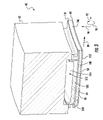
図3は、ガスタービン10の第1段に典型的な、外側タービンシュラウドセグメント62に連結されてタービンシュラウドブロックアセンブリ40を形成する内側タービンシュラウドセグメント60の一実施形態の斜視図である。タービン10は、それぞれのタービン段の周りにリングを一緒に形成する複数のタービンシュラウドブロックアセンブリ40を含む。特定の実施形態では、タービン10は、タービン10の回転軸の周りに周方向90に配置された各タービンシュラウドセグメント40のためのそれぞれの外側タービンシュラウドセグメント62に連結された複数の内側タービンシュラウドセグメント60を含んでもよい。他の実施形態では、タービン10は、外側タービンシュラウドセグメント62に連結されてタービンブロックアセンブリ40を形成する複数の内側タービンシュラウドセグメント60を含んでもよい。
FIG. 3 is a perspective view of one embodiment of inner
図示されているように、内側タービンシュラウドセグメント60は、上流の縁すなわち前縁104および下流の縁すなわち後縁106を有する本体102を含み、その両方が高温ガス流路30に接する。本体102はまた、前縁104および後縁106に対して略垂直に配置された第1の側部108(例えば、第1のスラッシュ面)および第2の側部110(例えば、第2のスラッシュ面)を含む。本体102は、一対の対向する側をさらに含み、燃焼ガス側112は前縁104と後縁106との間に延び、後側114は、第1の側部108と第2の側部110との間に延びる。特定の実施形態では、本体102(特に、対向する側112,114)は、第1の側部108と第2の側部110との間の周方向90において、および/または前縁104と後縁106との間の軸方向92において、円弧形状であってもよい。後側114は、内側タービンシュラウドセグメント60と外側タービンシュラウドセグメント62との間に画定されたキャビティ118と接するように構成される。
As shown, the inner
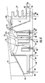
図4は、さまざまなチャネル74の経路および関連する移行マニホールド88の配置を示す冷却構造の実施形態の一部分である。図示されるように、本体102は、キャビティ118の傾斜した外周壁120から延びる複数のチャネル74を含み、冷却構造の第1の側部108に沿って配置される。本体102は、2~30個、またはそれ以上のチャネル74を含んでもよい。各チャネル74は、キャビティ118から吸気端76を介して冷却媒体200を受け入れ、排気ポート80で排気端82を介して使用済み冷却媒体を排出するように構成される。
FIG. 4 is a portion of an embodiment of a cooling structure showing the routing of
特定の実施形態では、チャネル74は、チャネル74に関して上述したような計量機構を含むことができる。いくつかの実施形態では、チャネルは、完全に鋳造され、液体ジェット誘導レーザ技術(液体マイクロジェットと呼ばれることもある)で切断され、付加製造プロセスで「3Dプリントされ」、EDM/ECMされ、または本体102内で燃焼ガス側112の近くで精密に機械加工されてもよい。冷却構造に使用できる付加製造技術には、バインダ噴射、指向性エネルギーデポジション、材料押出し、材料噴射、粉末床溶融、シートラミネーション、バット光重合、およびそれらの組み合わせが含まれる。
In certain embodiments,
図4~図7に示す例示的な実施形態は、異なる位置で移行マニホールド88を使用することによって可能にされる多くのマイクロチャネルパターンを含む本体102を有する。内側タービンシュラウドセグメント60は、通常、圧縮機12からの冷却媒体200に近接している。内側タービンシュラウドセグメント60は、冷却媒体200または空気を圧縮機12から受け入れるための吸気端76を含む。冷却媒体200は、後側114からチャネル74に延びる本体102内に配置された吸気端76を介して内側タービンシュラウドセグメント60の本体102内のチャネル74に流れる。各チャネル74は、図7Aに示されているように、ループ状部分78を含むことができ、ほとんどの任意のパターンは他の図に示されている。ただし、マイクロチャネルの経路およびパターンは、特定の方向または向きに限定されない。排気端82または吸気端76は、計量機構(例えば、チャネルの隣接する断面積に対してチャネルの一部の断面積を狭める、チャネル内に延びる本体102の一部分)を含むことができ、チャネル74内の冷却流体の流れを調節する。特定の実施形態では、各チャネル74自体(排気端部分を除く)は、計量機構(例えば、チャネル内に延びる本体102の一部を含む)として機能する。他の実施形態では、ループ状部分78または他のチャネル74部分に連結された吸気端76は、計量機構(例えば、吸気端76内に延びる本体102の一部)を含んでもよい。特定の実施形態では、チャネル74自体、排気端82、または吸気端76、またはそれらの組み合わせは、計量機構を含む。さらに、冷却流体は、第1の側部108、第2の側部110、前縁104、後縁106、またはそれらの組み合わせにおいて排気端82を介してチャネル74(および本体102)から出る。特定の実施形態では、チャネルは、第1の側部108に隣接して配置された吸気端76を有するチャネルの第1セット68と、第2の側部110に隣接して配置されたチャネルの第2セット70とで、交互のパターンで配置されてもよく、隣接するチャネルは反対の向きを有する。
The exemplary embodiment shown in FIGS. 4-7 has a
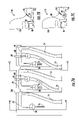
図4~図8において、供給または吸気冷却空気流が直線矢印記号を用いて示され、排気冷却空気流が「曲がりくねった(squiggly)」矢印記号を用いて示されている。図5A~図5Cにおいて、t字形部分86は、前縁104に隣接する冷却チャネル74の長さを増加させることにより、より大きな冷却領域を提供する。チャネルの各セット68、70、および72において、t字形部分86は互いに隣接して配置され、対向する側のマイクロチャネル74からの排気端82を組み込むことができる。吸気端76は、キャビティ118からチャネル74と流体連通している吸気移行マニホールド88まで延びている。排気端82は、t字形部分86から略半径方向外側に配置され、それにより、t字形部分86を互いに隣接して配置することを可能にする。各排気端82は、t字形部分86から略半径方向外側に配置された複数の排気ポート80から冷却空気を排出するように構成された移行マニホールド88から延びている。特定の実施形態では、本体102は、本体102の残りの部分に配置されたチャネルとは異なる形状の後縁106に隣接して配置されたチャネルを含む。例えば、後縁106に隣接するチャネルはそれぞれ蛇行パターンを含んでもよい。
In FIGS. 4-8, supply or inlet cooling airflow is indicated using straight arrow symbols, and exhaust cooling airflow is indicated using "squiggly" arrow symbols. 5A-5C, t-shaped
図6A~図6Cは、マイクロチャネル74を有する図5の変形例の平面図および断面図を示しており、ここで、t字形部分86は、ブリッジ部分96と相互接続されている。ブリッジ部分88は、前縁104の全長がマイクロチャネル74によって冷却されるように、前縁104に十分なマイクロチャネル冷却面を追加する。チャネルの各セット68、70、および72において、t字形部分86は、対向する側のマイクロチャネル74からの排気端82を組み込んでいる。吸気端76は、キャビティ118からチャネル74と流体連通している吸気移行マニホールド88まで延びている。排気端82は、t字形部分86から略半径方向外側に配置され、それによって、t字形部分86が互いに流体連通するように、t字形部分86をブリッジ部分96によって延長することができる。各排気端82は、t字形部分86から略半径方向外側に配置された複数の排気ポート80から冷却空気を排出するように構成された移行マニホールド88から延びている。特定の実施形態では、本体102は、本体102の残りの部分に配置されたチャネルとは異なる形状の後縁106に隣接して配置されたチャネルを含む。例えば、後縁106に隣接するチャネルはそれぞれ蛇行パターンを含んでもよい。
6A-6C show top and cross-sectional views of a variation of FIG. 5 having
図7A~図7Cは、マイクロチャネル74を有する例示的な実施形態の平面図および断面図を示しており、ここで、ループ状部分78は、ループの中央部分内に配置された排気移行マニホールド88を有する。チャネルの各セット68、70、および72において、ループ状部分78は、対向する側のマイクロチャネル74から排気端82を組み込んでいる。吸気端76は、キャビティ118からチャネル74と流体連通している吸気移行マニホールド88まで延びている。排気端82は、ループ状部分78から略半径方向外側に配置される。各排気端82は、ループ状部分78から略半径方向外側に配置された複数の排気ポート80から冷却空気を排出するように構成された移行マニホールド88から延びている。特定の実施形態では、本体102は、本体102の残りの部分に配置されたチャネルとは異なる形状の後縁106に隣接して配置されたチャネルを含む。例えば、後縁106に隣接するチャネルはそれぞれ蛇行パターンを含んでもよい。チャネル74の形状もまた、プラグされたチャネルの場合に適切な冷却を提供するように最適化される。開示された内側タービンシュラウドセグメント60の実施形態は、(例えば、タービンシュラウドのための典型的な冷却システムよりも)少ない空気で冷却することを可能にし、その結果、冷却に利用されるチャージ可能な空気に関連するコストを低減する。
7A-7C show top and cross-sectional views of an exemplary
図8Aおよび図8Bは、移行マニホールド88の追加の形状および特徴を示している。図8Aは、構造的完全性を維持するのに十分な金属リガメントで表面近くの既存のマイクロチャネル87をバイパスすることができる移行マニホールド88の深いプランジを示している。コーティング89を、熱的および構造的保護のために本体102の表面に適用することができる。深いプランジは、吸気端76および/または排気端82の接続部のためのより大きなまたはレーストラック形の孔を可能にする。図8Bは、出口における移行マニホールド88の余分なプランジ深さを示しており、これにより、排気端82においてより大きいL/D(長さ/直径)のフィルム孔を可能にすることができる。
8A and 8B show additional shapes and features of the
ここに記載された説明は、最良の形態を含む本発明を開示するため、また、任意の装置またはシステムの作成および使用、ならびに任意の組み合わせられた方法の実行を含み、当業者が本発明を実施できるようにするために例を用いる。開示の特許可能な範囲は、特許請求の範囲によって定義され、当業者が想到するその他の例を含むことができる。このような他の例が請求項の字義通りの文言と異ならない構造要素を含む場合、または、それらが請求項の字義通りの文言と実質的な差異がない等価な構造要素を含む場合には、このような他の例は特許請求の範囲内であることを意図している。
[実施態様1]
前縁(104)と、後縁(106)と、第1の側部(108)と、第2の側部(110)と、キャビティ(118)とを有する本体(102)と、
前記キャビティ(118)から延び、前記第1の側部(108)に沿って配置された冷却空気マイクロチャネル(74)の第1セット(68)と、
前記キャビティ(118)から延び、前記第2の側部(110)に沿って配置された冷却空気マイクロチャネル(74)の第2セット(70)と
を備えた、ガスタービンエンジンの冷却構造であって、
前記冷却空気マイクロチャネル(74)の各セット(68、70、72)は、隣接するマイクロチャネル(74)と流体連通し、吸気端(76)、排気端(82)、およびそれらの組み合わせのうちの少なくとも1つと流体連通している少なくとも1つの移行マニホールド(88)をさらに備える、
冷却構造。
[実施態様2]
前記キャビティ(118)から延び、前記前縁(104)および前記後縁(106)に沿って配置された冷却空気マイクロチャネル(74)の第3セット(72)を備える、実施態様1に記載の冷却構造。
[実施態様3]
前記移行マニホールド(88)の断面積が、前記隣接するマイクロチャネル(74)の断面積以上である、実施態様1に記載の冷却構造。
[実施態様4]
前記移行マニホールド(88)が、略半径方向外側の方向に延びる、実施態様1に記載の冷却構造。
[実施態様5]
前記吸気端(76)が、前記キャビティ(118)と流体連通している、実施態様1に記載の冷却構造。
[実施態様6]
前記排気端(82)が、ガスタービン(10)の高温ガス経路と流体連通している、実施態様1に記載の冷却構造。
[実施態様7]
前記キャビティ(118)が、燃焼ガス側(112)から半径方向外側に配置され、前記キャビティ(118)は、傾斜した外周壁(120)をさらに画定する、実施態様1に記載の冷却構造。
[実施態様8]
各吸気端(76)が、前記傾斜した外周壁(120)の周囲に配置され、冷却流路(44)から圧縮された冷却空気を受け入れるように構成されている、実施態様7に記載の冷却構造。
[実施態様9]
各マイクロチャネル(74)が、互いに隣接して配置され、前記少なくとも1つの移行マニホールド(88)と流体連通しているt字形部分(86)を備える、実施態様1に記載の冷却構造。
[実施態様10]
各マイクロチャネル(74)の前記t字形部分(86)が、隣接するt字形部分(86)と流体連通している、実施態様9に記載の冷却構造。
[実施態様11]
各マイクロチャネル(74)がループ形状の吸気端(76)を備え、前記移行マニホールド(88)は前記ループの中央部分内に配置されている、実施態様1に記載の冷却構造。
[実施態様12]
圧縮機セクション(12)と、
前記圧縮機の下流に位置する燃焼セクション(18)内の複数の燃焼器(20)と、
前記燃焼セクション(18)の下流に位置するタービンセクション(22)と、
を備えるガスタービン(10)であって、
前記ガスタービン(10)は複数の冷却構造を含み、各冷却構造は、
前縁(104)、後縁(106)、第1の側部(108)、第2の側部(110)、およびキャビティ(118)を有する本体(102)と、
前記キャビティ(118)から延び、前記第1の側部(108)に沿って配置された冷却空気マイクロチャネル(74)の第1セット(68)と、
前記キャビティ(118)から延び、前記第2の側部(110)に沿って配置された冷却空気マイクロチャネル(74)の第2セット(70)と
を備え、
前記冷却空気マイクロチャネル(74)の各セット(68、70、72)は、隣接するマイクロチャネル(74)と流体連通し、吸気端(76)、排気端(82)、およびそれらの組み合わせのうちの少なくとも1つと流体連通している少なくとも1つの移行マニホールド(88)をさらに備える、
ガスタービン(10)。
[実施態様13]
前記キャビティ(118)から延び、前記前縁(104)および前記後縁(106)に沿って配置された冷却空気マイクロチャネル(74)の第3セット(72)を備える、実施態様12に記載のガスタービン(10)。
[実施態様14]
前記移行マニホールド(88)の断面積が、前記隣接するマイクロチャネル(74)の断面積以上である、実施態様12に記載のガスタービン(10)。
[実施態様15]
前記吸気端(76)が、前記キャビティ(118)と流体連通している、実施態様12に記載のガスタービン(10)。
[実施態様16]
前記排気端(82)が、ガスタービン(10)の高温ガス経路と流体連通している、実施態様12に記載のガスタービン(10)。
[実施態様17]
前記キャビティ(118)が、燃焼ガス側(112)から半径方向外側に配置され、前記キャビティ(118)は、傾斜した外周壁(120)をさらに画定する、実施態様12に記載のガスタービン(10)。
[実施態様18]
各吸気端(76)が、前記傾斜した外周壁(120)の周囲に配置され、冷却流路(44)から圧縮された冷却空気を受け入れるように構成されている、実施態様17に記載のガスタービン(10)。
[実施態様19]
各マイクロチャネル(74)が、互いに隣接して配置され、前記少なくとも1つの移行マニホールド(88)と流体連通しているt字形部分(86)を備える、実施態様12に記載のガスタービン(10)。
[実施態様20]
各マイクロチャネル(74)の前記t字形部分(86)が、隣接するt字形部分(86)と流体連通している、実施態様19に記載のガスタービン(10)。
This written description is intended to disclose the invention, including the best mode, and also includes making and using any apparatus or system, and performing any combined method, to enable a person skilled in the art to make and use the invention. An example is used to enable implementation. The patentable scope of the disclosure is defined by the claims, and may include other examples that occur to those skilled in the art. Where such other examples contain structural elements that do not differ from the literal language of the claims, or where they contain equivalent structural elements that do not materially differ from the literal language of the claims. , and other such examples are intended to be within the scope of the claims.
[Embodiment 1]
a body (102) having a leading edge (104), a trailing edge (106), a first side (108), a second side (110) and a cavity (118);
a first set (68) of cooling air microchannels (74) extending from said cavity (118) and arranged along said first side (108);
a second set (70) of cooling air microchannels (74) extending from said cavity (118) and disposed along said second side (110). hand,
Each set (68, 70, 72) of said cooling air microchannels (74) is in fluid communication with an adjacent microchannel (74) and includes an inlet end (76), an outlet end (82), and combinations thereof. further comprising at least one transition manifold (88) in fluid communication with at least one of
cooling structure.
[Embodiment 2]
2. The method of claim 1, comprising a third set (72) of cooling air microchannels (74) extending from said cavity (118) and arranged along said leading edge (104) and said trailing edge (106). cooling structure.
[Embodiment 3]
2. The cooling structure of claim 1, wherein the cross-sectional area of said transition manifold (88) is greater than or equal to the cross-sectional area of said adjacent microchannel (74).
[Embodiment 4]
2. The cooling structure of claim 1, wherein said transition manifold (88) extends in a generally radially outward direction.
[Embodiment 5]
2. The cooling structure of claim 1, wherein said intake end (76) is in fluid communication with said cavity (118).
[Embodiment 6]
The cooling structure of claim 1, wherein said exhaust end (82) is in fluid communication with a hot gas path of a gas turbine (10).
[Embodiment 7]
2. The cooling structure of claim 1, wherein said cavity (118) is located radially outwardly from a combustion gas side (112), said cavity (118) further defining an inclined outer peripheral wall (120).
[Embodiment 8]
8. The cooling of claim 7, wherein each intake end (76) is disposed about said sloped peripheral wall (120) and is configured to receive compressed cooling air from cooling channels (44). structure.
[Embodiment 9]
2. The cooling structure of claim 1, wherein each microchannel (74) comprises a t-shaped portion (86) positioned adjacent to each other and in fluid communication with said at least one transition manifold (88).
[Embodiment 10]
10. The cooling structure of embodiment 9, wherein said t-shaped portion (86) of each microchannel (74) is in fluid communication with an adjacent t-shaped portion (86).
[Embodiment 11]
2. The cooling structure of claim 1, wherein each microchannel (74) comprises a loop-shaped inlet end (76), and wherein said transition manifold (88) is located within a central portion of said loop.
[Embodiment 12]
a compressor section (12);
a plurality of combustors (20) in a combustion section (18) located downstream of the compressor;
a turbine section (22) located downstream of the combustion section (18);
A gas turbine (10) comprising:
The gas turbine (10) includes a plurality of cooling structures, each cooling structure comprising:
a body (102) having a leading edge (104), a trailing edge (106), a first side (108), a second side (110), and a cavity (118);
a first set (68) of cooling air microchannels (74) extending from said cavity (118) and arranged along said first side (108);
a second set (70) of cooling air microchannels (74) extending from said cavity (118) and arranged along said second side (110);
Each set (68, 70, 72) of said cooling air microchannels (74) is in fluid communication with an adjacent microchannel (74) and includes an inlet end (76), an outlet end (82), and combinations thereof. further comprising at least one transition manifold (88) in fluid communication with at least one of
A gas turbine (10).
[Embodiment 13]
13. The method of
[Embodiment 14]
13. The gas turbine (10) of
[Embodiment 15]
13. The gas turbine (10) of
[Embodiment 16]
13. The gas turbine (10) of
[Embodiment 17]
13. The gas turbine (10) according to
[Embodiment 18]
18. The gas of claim 17, wherein each intake end (76) is disposed about said sloped peripheral wall (120) and is configured to receive compressed cooling air from cooling channels (44). turbine (10).
[Embodiment 19]
13. The gas turbine (10) according to
[Embodiment 20]
20. The gas turbine (10) according to embodiment 19, wherein said t-shaped portion (86) of each microchannel (74) is in fluid communication with an adjacent t-shaped portion (86).
10 ガスタービン
12 圧縮機セクション、圧縮機
14 入口
16 ケーシング
18 燃焼セクション
20 燃焼器
22 タービンセクション
24 ロータシャフト
26 空気
28 圧縮空気
30 高温ガス、高温ガス流路
32 第1段
34 タービンノズル
36 ロータブレード
38 タービンケーシング、外側ケーシング
40 タービンシュラウドブロックアセンブリ、タービンシュラウドセグメント
42 先端部
44 冷却流路
46 取り付けハードウェア
60 内側タービンシュラウドセグメント
62 外側タービンシュラウドセグメント
68 チャネルの第1セット
70 チャネルの第2セット
72 チャネルのセット
74 マイクロチャネル、冷却チャネル
76 吸気端
78 ループ状部分
80 排気ポート
82 排気端
86 t字形部分
87 マイクロチャネル
88 吸気移行マニホールド、排気移行マニホールド、ブリッジ部分
89 コーティング
90 周方向
92 軸方向
94 半径方向
96 ブリッジ部分
100 シュラウドブロックセグメント
102 本体
104 前縁
106 後縁
108 第1の側部
110 第2の側部
112 燃焼ガス側
114 後側
118 キャビティ
120 傾斜した外周壁
200 冷却媒体
10
Claims (10)
前縁(104)、後縁(106)、第1の側部(108)、第2の側部(110)及びキャビティ(118)とを有する本体(102)と、
前記キャビティ(118)から延び、前記第1の側部(108)に沿って配置された冷却空気マイクロチャネル(74)の第1セット(68)と、
前記キャビティ(118)から延び、前記第2の側部(110)に沿って配置された冷却空気マイクロチャネル(74)の第2セット(70)と
を備えており、
前記冷却空気マイクロチャネル(74)の第1のセット及び第2のセットの各々の冷却空気マイクロチャネルが、吸気端(76)と、該吸気端(76)に連結されたループ状部分(78)と、排気端(82)と、前記吸気端(76)及び前記排気端(82)の少なくとも一方と流体連通した少なくとも1つの移行マニホールド(88)をさらに備えており、前記少なくとも1つの移行マニホールド(88)が、前記排気端(82)と流体連通した排気移行マニホールド(88)を含んでおり、冷却空気マイクロチャネルの第1のセット又は第2のセットの排気移行マニホールド(88)が、冷却空気マイクロチャネルの他方のセットのうちの隣接する冷却空気マイクロチャネルのループ状部分(78)の中央部分内に配置されている、冷却構造。 A cooling structure for a gas turbine engine, the cooling structure comprising:
a body (102) having a leading edge (104) , a trailing edge (106) , a first side (108) , a second side (110) and a cavity (118);
a first set (68) of cooling air microchannels (74) extending from said cavity (118) and arranged along said first side (108);
a second set (70) of cooling air microchannels (74) extending from said cavity (118) and arranged along said second side (110);
Each cooling air microchannel of the first and second sets of cooling air microchannels (74) has an inlet end (76) and a looped portion (78) connected to the inlet end (76). an exhaust end (82); and at least one transition manifold (88) in fluid communication with at least one of the intake end (76) and the exhaust end (82) , the at least one transition manifold (88) includes an exhaust transition manifold (88) in fluid communication with the exhaust end (82), the exhaust transition manifold (88) of the first set or the second set of cooling air microchannels providing cooling; A cooling structure disposed within a central portion of a looped portion (78) of an adjacent cooling air microchannel of the other set of air microchannels .
前記圧縮機セクション(12)の下流に位置する燃焼セクション(18)内の少なくとも1つの燃焼器(20)と、
前記燃焼セクション(18)の下流に位置するタービンセクション(22)と
を備えるガスタービン(10)であって、当該ガスタービン(10)が、請求項1乃至請求項9のいずれか1項に記載の冷却構造を複数含む、ガスタービン(10)。 a compressor section (12);
at least one combustor (20) in a combustion section (18) located downstream of the compressor section (12) ;
a turbine section (22) located downstream of the combustion section (18) ;
10. A gas turbine (10) comprising a plurality of cooling structures according to any one of claims 1 to 9 .
Applications Claiming Priority (2)
| Application Number | Priority Date | Filing Date | Title |
|---|---|---|---|
| US15/343,369 | 2016-11-04 | ||
| US15/343,369 US10519861B2 (en) | 2016-11-04 | 2016-11-04 | Transition manifolds for cooling channel connections in cooled structures |
Publications (2)
| Publication Number | Publication Date |
|---|---|
| JP2018115654A JP2018115654A (en) | 2018-07-26 |
| JP7109901B2 true JP7109901B2 (en) | 2022-08-01 |
Family
ID=60201419
Family Applications (1)
| Application Number | Title | Priority Date | Filing Date |
|---|---|---|---|
| JP2017204128A Active JP7109901B2 (en) | 2016-11-04 | 2017-10-23 | Transition manifold for cooling channel connections of cooling structures |
Country Status (4)
| Country | Link |
|---|---|
| US (1) | US10519861B2 (en) |
| EP (1) | EP3318721B1 (en) |
| JP (1) | JP7109901B2 (en) |
| CN (1) | CN108019240B (en) |
Families Citing this family (4)
| Publication number | Priority date | Publication date | Assignee | Title |
|---|---|---|---|---|
| US10443437B2 (en) * | 2016-11-03 | 2019-10-15 | General Electric Company | Interwoven near surface cooled channels for cooled structures |
| US10731487B2 (en) | 2017-02-20 | 2020-08-04 | General Electric Company | Turbine components and methods of manufacturing |
| US11015481B2 (en) | 2018-06-22 | 2021-05-25 | General Electric Company | Turbine shroud block segment with near surface cooling channels |
| RU201312U1 (en) * | 2020-07-21 | 2020-12-09 | Федеральное государственное бюджетное образовательное учреждение высшего образования "Рыбинский государственный авиационный технический университет имени П.А. Соловьева" | Cooled turbine nozzle blade of a gas turbine engine |
Citations (4)
| Publication number | Priority date | Publication date | Assignee | Title |
|---|---|---|---|---|
| JP2005140119A (en) | 2003-11-10 | 2005-06-02 | General Electric Co <Ge> | Cooling system for nozzle segment platform edge |
| JP2010001764A (en) | 2008-06-18 | 2010-01-07 | Mitsubishi Heavy Ind Ltd | Divided ring cooling structure |
| US20120057960A1 (en) | 2010-09-07 | 2012-03-08 | Berrong Eric C | Ring segment with forked cooling passages |
| JP2015017607A (en) | 2013-07-08 | 2015-01-29 | ゼネラル・エレクトリック・カンパニイ | Shroud block segment for gas turbine |
Family Cites Families (36)
| Publication number | Priority date | Publication date | Assignee | Title |
|---|---|---|---|---|
| US3844679A (en) | 1973-03-28 | 1974-10-29 | Gen Electric | Pressurized serpentine cooling channel construction for open-circuit liquid cooled turbine buckets |
| US4353679A (en) | 1976-07-29 | 1982-10-12 | General Electric Company | Fluid-cooled element |
| US5584651A (en) * | 1994-10-31 | 1996-12-17 | General Electric Company | Cooled shroud |
| US5957657A (en) | 1996-02-26 | 1999-09-28 | Mitisubishi Heavy Industries, Ltd. | Method of forming a cooling air passage in a gas turbine stationary blade shroud |
| US5993150A (en) * | 1998-01-16 | 1999-11-30 | General Electric Company | Dual cooled shroud |
| US6247896B1 (en) | 1999-06-23 | 2001-06-19 | United Technologies Corporation | Method and apparatus for cooling an airfoil |
| US6241467B1 (en) | 1999-08-02 | 2001-06-05 | United Technologies Corporation | Stator vane for a rotary machine |
| US6905302B2 (en) | 2003-09-17 | 2005-06-14 | General Electric Company | Network cooled coated wall |
| US7505946B2 (en) | 2004-03-31 | 2009-03-17 | Microsoft Corporation | High performance content alteration architecture and techniques |
| US7653994B2 (en) | 2006-03-22 | 2010-02-02 | General Electric Company | Repair of HPT shrouds with sintered preforms |
| US7900458B2 (en) | 2007-05-29 | 2011-03-08 | Siemens Energy, Inc. | Turbine airfoils with near surface cooling passages and method of making same |
| US7988410B1 (en) * | 2007-11-19 | 2011-08-02 | Florida Turbine Technologies, Inc. | Blade tip shroud with circular grooves |
| US8109726B2 (en) | 2009-01-19 | 2012-02-07 | Siemens Energy, Inc. | Turbine blade with micro channel cooling system |
| US8182224B1 (en) | 2009-02-17 | 2012-05-22 | Florida Turbine Technologies, Inc. | Turbine blade having a row of spanwise nearwall serpentine cooling circuits |
| US8721285B2 (en) | 2009-03-04 | 2014-05-13 | Siemens Energy, Inc. | Turbine blade with incremental serpentine cooling channels beneath a thermal skin |
| US8096772B2 (en) | 2009-03-20 | 2012-01-17 | Siemens Energy, Inc. | Turbine vane for a gas turbine engine having serpentine cooling channels within the inner endwall |
| US8360726B1 (en) | 2009-09-17 | 2013-01-29 | Florida Turbine Technologies, Inc. | Turbine blade with chordwise cooling channels |
| US8388300B1 (en) | 2010-07-21 | 2013-03-05 | Florida Turbine Technologies, Inc. | Turbine ring segment |
| US8684662B2 (en) | 2010-09-03 | 2014-04-01 | Siemens Energy, Inc. | Ring segment with impingement and convective cooling |
| US8777568B2 (en) | 2010-09-30 | 2014-07-15 | General Electric Company | Apparatus and methods for cooling platform regions of turbine rotor blades |
| US20120114868A1 (en) | 2010-11-10 | 2012-05-10 | General Electric Company | Method of fabricating a component using a fugitive coating |
| US8511995B1 (en) | 2010-11-22 | 2013-08-20 | Florida Turbine Technologies, Inc. | Turbine blade with platform cooling |
| US8770936B1 (en) | 2010-11-22 | 2014-07-08 | Florida Turbine Technologies, Inc. | Turbine blade with near wall cooling channels |
| US8449246B1 (en) | 2010-12-01 | 2013-05-28 | Florida Turbine Technologies, Inc. | BOAS with micro serpentine cooling |
| US8845272B2 (en) * | 2011-02-25 | 2014-09-30 | General Electric Company | Turbine shroud and a method for manufacturing the turbine shroud |
| US8870523B2 (en) | 2011-03-07 | 2014-10-28 | General Electric Company | Method for manufacturing a hot gas path component and hot gas path turbine component |
| US8632298B1 (en) | 2011-03-21 | 2014-01-21 | Florida Turbine Technologies, Inc. | Turbine vane with endwall cooling |
| US8734111B2 (en) | 2011-06-27 | 2014-05-27 | General Electric Company | Platform cooling passages and methods for creating platform cooling passages in turbine rotor blades |
| US9127549B2 (en) | 2012-04-26 | 2015-09-08 | General Electric Company | Turbine shroud cooling assembly for a gas turbine system |
| US20140126995A1 (en) | 2012-11-06 | 2014-05-08 | General Electric Company | Microchannel cooled turbine component and method of forming a microchannel cooled turbine component |
| GB201223193D0 (en) * | 2012-12-21 | 2013-02-06 | Rolls Royce Plc | Turbine blade |
| US9015944B2 (en) | 2013-02-22 | 2015-04-28 | General Electric Company | Method of forming a microchannel cooled component |
| US20140360155A1 (en) | 2013-06-07 | 2014-12-11 | General Electric Company | Microchannel systems and methods for cooling turbine components of a gas turbine engine |
| EP2860358A1 (en) | 2013-10-10 | 2015-04-15 | Alstom Technology Ltd | Arrangement for cooling a component in the hot gas path of a gas turbine |
| EP3096912A4 (en) * | 2014-01-22 | 2017-02-01 | United Technologies Corporation | Method for additively constructing internal channels |
| US9995172B2 (en) | 2015-10-12 | 2018-06-12 | General Electric Company | Turbine nozzle with cooling channel coolant discharge plenum |
-
2016
- 2016-11-04 US US15/343,369 patent/US10519861B2/en active Active
-
2017
- 2017-10-23 JP JP2017204128A patent/JP7109901B2/en active Active
- 2017-10-31 EP EP17199314.0A patent/EP3318721B1/en active Active
- 2017-11-03 CN CN201711075120.8A patent/CN108019240B/en active Active
Patent Citations (4)
| Publication number | Priority date | Publication date | Assignee | Title |
|---|---|---|---|---|
| JP2005140119A (en) | 2003-11-10 | 2005-06-02 | General Electric Co <Ge> | Cooling system for nozzle segment platform edge |
| JP2010001764A (en) | 2008-06-18 | 2010-01-07 | Mitsubishi Heavy Ind Ltd | Divided ring cooling structure |
| US20120057960A1 (en) | 2010-09-07 | 2012-03-08 | Berrong Eric C | Ring segment with forked cooling passages |
| JP2015017607A (en) | 2013-07-08 | 2015-01-29 | ゼネラル・エレクトリック・カンパニイ | Shroud block segment for gas turbine |
Also Published As
| Publication number | Publication date |
|---|---|
| CN108019240A (en) | 2018-05-11 |
| EP3318721B1 (en) | 2023-01-11 |
| US20180128174A1 (en) | 2018-05-10 |
| US10519861B2 (en) | 2019-12-31 |
| CN108019240B (en) | 2022-06-17 |
| EP3318721A1 (en) | 2018-05-09 |
| JP2018115654A (en) | 2018-07-26 |
Similar Documents
| Publication | Publication Date | Title |
|---|---|---|
| EP3318720B1 (en) | Cooled structure for a gas turbine, corresponding gas turbine and method of making a cooled structure | |
| US9464538B2 (en) | Shroud block segment for a gas turbine | |
| JP6496499B2 (en) | Turbine component and method of assembling it | |
| JP7109901B2 (en) | Transition manifold for cooling channel connections of cooling structures | |
| US9938899B2 (en) | Hot gas path component having cast-in features for near wall cooling | |
| EP2912276B1 (en) | Film cooling channel array | |
| US11927110B2 (en) | Component for a turbine engine with a cooling hole | |
| EP3203024B1 (en) | Rotor blade and corresponding gas turbine | |
| EP3181825B1 (en) | Shroud segment with hook-shaped cooling channels | |
| EP3181826B1 (en) | Shroud segment with trailing edge cooling channels and hook-shaped side edge cooling channels | |
| US11499434B2 (en) | Cooled airfoil and method of making | |
| EP3228821A1 (en) | System and method for cooling trailing edge and/or leading edge of hot gas flow path component | |
| JP2017110661A (en) | System and method for utilizing target features in forming inlet passages in micro-channel circuit | |
| US10760431B2 (en) | Component for a turbine engine with a cooling hole | |
| CN112343665B (en) | Engine component with cooling holes | |
| JP2017110655A (en) | Method for metering micro-channel circuit | |
| JP7341743B2 (en) | Overlapping near-surface cooling channels | |
| US11053809B2 (en) | Turbine engine airfoil |
Legal Events
| Date | Code | Title | Description |
|---|---|---|---|
| RD04 | Notification of resignation of power of attorney |
Free format text: JAPANESE INTERMEDIATE CODE: A7424 Effective date: 20190527 |
|
| A621 | Written request for application examination |
Free format text: JAPANESE INTERMEDIATE CODE: A621 Effective date: 20201016 |
|
| A977 | Report on retrieval |
Free format text: JAPANESE INTERMEDIATE CODE: A971007 Effective date: 20210721 |
|
| A131 | Notification of reasons for refusal |
Free format text: JAPANESE INTERMEDIATE CODE: A131 Effective date: 20210803 |
|
| A601 | Written request for extension of time |
Free format text: JAPANESE INTERMEDIATE CODE: A601 Effective date: 20211101 |
|
| A521 | Request for written amendment filed |
Free format text: JAPANESE INTERMEDIATE CODE: A523 Effective date: 20220202 |
|
| TRDD | Decision of grant or rejection written | ||
| A01 | Written decision to grant a patent or to grant a registration (utility model) |
Free format text: JAPANESE INTERMEDIATE CODE: A01 Effective date: 20220622 |
|
| A61 | First payment of annual fees (during grant procedure) |
Free format text: JAPANESE INTERMEDIATE CODE: A61 Effective date: 20220720 |
|
| R150 | Certificate of patent or registration of utility model |
Ref document number: 7109901 Country of ref document: JP Free format text: JAPANESE INTERMEDIATE CODE: R150 |
|
| S111 | Request for change of ownership or part of ownership |
Free format text: JAPANESE INTERMEDIATE CODE: R313113 |
|
| R350 | Written notification of registration of transfer |
Free format text: JAPANESE INTERMEDIATE CODE: R350 |