EP2511153A1 - A Steering Wheel - Google Patents
A Steering Wheel Download PDFInfo
- Publication number
- EP2511153A1 EP2511153A1 EP11161383A EP11161383A EP2511153A1 EP 2511153 A1 EP2511153 A1 EP 2511153A1 EP 11161383 A EP11161383 A EP 11161383A EP 11161383 A EP11161383 A EP 11161383A EP 2511153 A1 EP2511153 A1 EP 2511153A1
- Authority
- EP
- European Patent Office
- Prior art keywords
- steering wheel
- rim
- recess
- outer skin
- insert
- Prior art date
- Legal status (The legal status is an assumption and is not a legal conclusion. Google has not performed a legal analysis and makes no representation as to the accuracy of the status listed.)
- Withdrawn
Links
- 239000004033 plastic Substances 0.000 claims abstract description 19
- 229920003023 plastic Polymers 0.000 claims abstract description 19
- 230000015572 biosynthetic process Effects 0.000 claims abstract description 16
- 239000000463 material Substances 0.000 claims abstract description 11
- 239000010985 leather Substances 0.000 claims abstract description 9
- 239000002649 leather substitute Substances 0.000 claims abstract description 7
- 238000003466 welding Methods 0.000 claims abstract description 7
- 230000001419 dependent effect Effects 0.000 claims 1
- 239000006260 foam Substances 0.000 description 11
- 238000005755 formation reaction Methods 0.000 description 9
- 239000002184 metal Substances 0.000 description 4
- 238000000034 method Methods 0.000 description 4
- 230000000007 visual effect Effects 0.000 description 3
- 238000001125 extrusion Methods 0.000 description 2
- 238000001746 injection moulding Methods 0.000 description 2
- 230000002093 peripheral effect Effects 0.000 description 2
- 239000004743 Polypropylene Substances 0.000 description 1
- 229920005830 Polyurethane Foam Polymers 0.000 description 1
- 230000002301 combined effect Effects 0.000 description 1
- 238000010276 construction Methods 0.000 description 1
- 230000000694 effects Effects 0.000 description 1
- 239000006261 foam material Substances 0.000 description 1
- 230000004927 fusion Effects 0.000 description 1
- 238000002347 injection Methods 0.000 description 1
- 239000007924 injection Substances 0.000 description 1
- 238000004519 manufacturing process Methods 0.000 description 1
- 238000002844 melting Methods 0.000 description 1
- 230000008018 melting Effects 0.000 description 1
- 238000012986 modification Methods 0.000 description 1
- 230000004048 modification Effects 0.000 description 1
- -1 polypropylene Polymers 0.000 description 1
- 229920001155 polypropylene Polymers 0.000 description 1
- 239000011496 polyurethane foam Substances 0.000 description 1
- 238000003825 pressing Methods 0.000 description 1
- 230000036642 wellbeing Effects 0.000 description 1
Images






Classifications
-
- B—PERFORMING OPERATIONS; TRANSPORTING
- B62—LAND VEHICLES FOR TRAVELLING OTHERWISE THAN ON RAILS
- B62D—MOTOR VEHICLES; TRAILERS
- B62D1/00—Steering controls, i.e. means for initiating a change of direction of the vehicle
- B62D1/02—Steering controls, i.e. means for initiating a change of direction of the vehicle vehicle-mounted
- B62D1/04—Hand wheels
- B62D1/06—Rims, e.g. with heating means; Rim covers
-
- Y—GENERAL TAGGING OF NEW TECHNOLOGICAL DEVELOPMENTS; GENERAL TAGGING OF CROSS-SECTIONAL TECHNOLOGIES SPANNING OVER SEVERAL SECTIONS OF THE IPC; TECHNICAL SUBJECTS COVERED BY FORMER USPC CROSS-REFERENCE ART COLLECTIONS [XRACs] AND DIGESTS
- Y10—TECHNICAL SUBJECTS COVERED BY FORMER USPC
- Y10T—TECHNICAL SUBJECTS COVERED BY FORMER US CLASSIFICATION
- Y10T74/00—Machine element or mechanism
- Y10T74/20—Control lever and linkage systems
- Y10T74/20576—Elements
- Y10T74/20732—Handles
- Y10T74/20834—Hand wheels
- Y10T74/2087—Rim grips and covers
Definitions
- the present invention relates to a steering wheel, for example of the sort found in a motor vehicle.
- Conventional steering wheels suitable for use in motor vehicles typically comprise a metal frame having a central boss from which one or more spokes extend in a generally radial direction.
- a generally circular or near-circular metal armature is supported by the radially outermost ends of the spokes in order to define part of a peripheral rim of the steering wheel, to be gripped by the driver of the vehicle.
- the armature is typically covered by a resilient covering, and the covering is finished with an outer skin.
- the outer skin is applied over the resilient covering to provide a visually and haptically pleasing peripheral surface to the steering wheel. It is conventional for the outer skin to be provided with a surface relief pattern of some sort, partly to improve the appearance and feel of the steering wheel, but also to provide an appropriate level of friction between the wheel and the hands of the driver to ensure the wheel can be properly gripped in use.
- the external appearance of a motor vehicle steering wheel has a significant effect on the general feeling of wellbeing imparted to the driver of the vehicle and can thus play a role in a person's purchase decision when choosing a new car.
- a steering wheel having a gripping formation comprising an armature substantially encapsulated by a cover of foamed material, and a flexible outer skin provided over and around the cover, the steering wheel being characterised by the provision of a plastic insert engaged within a fixing groove or recess formed in the cover, wherein at least one edge of the outer skin is positioned within the fixing groove or recess and fixed to the insert therein by means of ultrasonic welding.
- the outer skin is formed of leather or artificial leather.
- two opposed edges of the outer skin are both received within the fixing groove or recess and fixed to the insert therein by means of ultrasonic welding.
- said opposed edges of the outer skin are each fixed to spaced apart side walls of the insert.
- said gripping formation includes a rim of the steering wheel and said fixing groove or recess is formed around substantially the entire extent of the rim, generally circumferentially with respect to the steering wheel.
- the fixing groove or recess is formed around a front region of the rim.
- the steering wheel further comprises a decorative element engaged with or otherwise affixed to the insert so as to substantially cover the or each edge of the outer skin positioned within the fixing groove or recess.
- the decorative element is elongate.
- the decorative element substantially conforms to the path of the fixing groove or recess around the rim of the steering wheel.
- the free ends of the decorative element are positioned generally adjacent one another and are covered by a second decorative element.
- the decorative element is flexible.
- the decorative element is formed of plastic material.
- the decorative element is formed by an extrusion process.
- the decorative element may be injection moulded.
- the decorative element is clipped to the insert or engaged with the insert as an interference fit.
- the decorative element has a chromatic surface.
- the outer skin comprises at least one locating formation on its rear surface, the or each location formation being received within a respective locating groove or recess formed in the cover.
- said gripping formation includes a rim of the steering wheel and at least one said locating groove or recess is formed around substantially the entire extent of the rim, circumferentially with respect to the steering wheel.
- said locating groove or recess is formed around a rear part of the rim.
- At least one said locating groove or recess is formed around the radial cross-section of the rim.
- At least one said locating groove or recess is formed around an inner part of the rim.
- the outer skin is formed from a plurality of discrete interconnected panels.
- said panels are interconnected at least one seam, the or each seam comprising overlapped regions of at least two discrete panels.
- the or each said seam defines a respective said locating formation, and the overlapped regions of said panels forming each seam are located in a respective locating groove or recess.
- a steering wheel 1 comprising a central hub 2 from which a plurality of spokes 3 extend substantially radially, the spokes supporting an outer rim 4.
- the particular steering wheel illustrated comprises two spokes 3, but it should be appreciated that steering wheels in accordance with the invention could comprise more spokes than this, or could even comprise just a single spoke. More particularly, it is to be noted that the radially outermost ends of the spokes 3 support a generally circular or approximately circular metal armature 5 (illustrated in dashed lines in figure 1 ). Together, the hub 2, spokes 3, and armature 5 of the steering wheel can be considered to form an integral frame.
- the armature 5, and optionally at least a region of the spokes 3 may be provided with a foam cover 6.
- the cover 6 is formed from foamed material and may, for example, comprise polyurethane foam or expanded polypropylene.
- the foam cover 6 serves to completely encapsulate the underlying armature 5 whilst also cover the radially outermost region of each spoke 3.
- the steering wheel 1 is generally conventional.
- the foam cover 6 is wrapped with an outer skin 7.
- the present invention most particularly concerns the manner in which the outer skin 7 is affixed to the gripping portion of the steering wheel.
- the outer skin 7 takes the form of a relatively thin flexible sheet, and is preferably either natural leather or artificial leather having similar visual and haptic properties to natural leather.
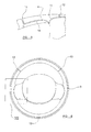
- Figure 2 shows a cross-section through the rim 4 of the steering wheel, taken along line II-II in figure 2 , but with the outer skin 7 omitted.
- the central armature 5 has a generally U-shaped profile in radial cross-section. This profile is not essential to the invention however.
- the armature 5 is encapsulated by the foam cover 6 which has a generally circular or slightly ovoid radial cross-section.
- a fixing groove 8 is formed in the cover 6.
- the fixing groove 8 has a substantially square or rectangular cross-sectional profile and preferably extends around substantially the entire extent of the rim 4, generally circumferentially with respect to the steering wheel as illustrated most clearly in figure 3 .
- the fixing groove 8 is formed around a front region of the rim 4 (i.e. a region of the rim which will face the driver of the vehicle).
- the fixing groove could be provided elsewhere about the radial cross-section of the rim 4, for example on the outside or perhaps on the rear part, facing away from the driver.
- the fixing groove 8 is open along its entire length.
- Figure 2 also shows a first locating groove 9 formed in the cover 6.
- the locating groove 9 also has a substantially square or rectangular cross-sectional profile and preferably extends around substantially the entire extent of the rim 4, generally circumferentially with respect to the steering wheel as illustrated most clearly in figure 3 .
- the locating groove 9 is formed around a rear region of the rim 4 (i.e. a region of the rim which will face away from the driver of the vehicle) and is thus diametrically opposed to the fixing groove 8 across the rim 4.
- the locating groove 9 could be provided elsewhere about the radial cross-section of the rim 4.
- the locating groove 9 is open along its entire length and preferably has a somewhat smaller cross-sectional profile than the fixing groove 8.
- an enlarged recess 10 may be provided within the outer cover 6, at a position along the fixing groove 8.
- the recess 10 is located at the "six o'clock position" around the rim 4.
- the fixing groove 8 thus effectively runs from one side of the recess 10, around the rim 4, and back to the other side of the recess 10.
- Figure 4 shows in detail the region IV of the steering wheel 1 denoted in figure 3 , and thus shows the intersection between a spoke 3 and the rim 4.
- the foam covering 6 also extends over the spoke 3 and this is clearly shown in figure 4.
- Figure 4 also shows two finishing grooves formed in the foam cover 6. The first of these is a groove 11 which extends in a generally arcuate manner around the intersection between the spoke 3 and the rim 4 of the steering wheel.
- Figure 7 shows the section of this groove which passes round the rear part of the spoke 3.
- the second finishing groove 12 runs in a generally radial direction relative the steering wheel as a whole, and extends across the front part of the rim 4 from the mid-point (or thereabouts) of the first finishing groove 11 on the front of the wheel to the fixing groove 8.
- Each spoke of the steering wheel has a respective first groove 11 formed around its foam covering 6, and also a respective second groove 12.
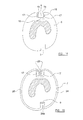
- Figure 5 shows in detail the region V of the steering wheel 1 denoted in figure 3 , and thus shows the radially inwardly facing region of the rim 4, adjacent the spoke 3.
- a second locating groove 13 which is formed in the foam cover 6 and which extends around the radial cross-section of the rim 4.
- the steering wheel 1 may be provided with a plurality of these radial locating grooves 13, for example as shown in figure 6 in which the steering wheel has three such grooves spaced around its rim 4.
- a third locating groove 14 is also provided, the third locating groove 14 being formed in the foam cover 6 around the inner part of the rim 4 and which extends from the second locating groove to the groove 11 formed around the end of the spoke 3.
- the plastic insert element takes the form of an elongate open channel of generally U-shaped cross-section having a base 16 supporting a pair of upstanding spaced-apart side-walls 17. Each side-wall 17 terminates with an inwardly directed projection 18 in the form of a gripping tooth or the like.
- the insert 15 is preferably flexible along its length and its side-walls are resiliently deformable.
- the insert 15 may be formed via a plastic extrusion process and from any suitable plastics material providing that the material is susceptible to melting and fusion upon application of ultrasonic energy. However, it is currently proposed to form the insert element 15 via an injection moulding process, in which case it is proposed that the insert 15 will have a pre-formed ring shape, in its relaxed condition, corresponding to the path of the fixing groove 8.
- Figure 9 shows an elongate decorative element 19.
- the decorative element 19 can be formed from metal, plastic, or indeed any other suitable material deemed to provide a suitable visual appearance within the context of a motor vehicle cabin.
- the decorative element 19 illustrated has a generally T-shaped cross-sectional profile comprising a head portion 20 from which a shank portion 21 depends.
- the shank portion 21 has a plurality of gripping formations which preferably take the form of outwardly directed projections 22.
- the head portion 20 has an outwardly presented surface 23 which is configured to have appropriate visual and haptic properties for the vehicle in which the steering wheel is intended to be used.
- the outer surface 23 may have a matt finish, a gloss finish, and/or may be chromatic.
- the decorative element 19 can be provided in alternative configurations and may, for example, have a generally rectangular cross-sectional profile without the gripping formations. It is proposed to pre-from the decorative element 19 into a shape corresponding to the path of the fixing groove 8, which in the arrangement illustrated involves pre-forming the decorative element 19 into the shape of a ring.
- Figure 10 shows a plurality of individual panels which have been cut from a sheet of leather or artificial leather.
- the panels include three rectangular outer panels 24 (in the sense that they will ultimately be wrapped over respective radially outwardly directed parts of the rim 4), and a single rectangular inner panel 25. Shown located on each side of the rectangular inner panel 25 are a pair of mirror-symmetrical large inner panels 26 and a pair of respective mirror-symmetrical small inner panels 27.
- the mirror-symmetrical panels 26, 27 each have a somewhat complicated shape comprising arcuate edges such that they will fit around the rim 4 of the steering wheel in the region where it meats the spokes 3.
- Figure 11 shows the panels 24-27 of figure 10 interconnected to one another along abutting edge regions so as to form a single elongate skin 7.
- Figure 12 shows a region of the resulting skin 7 as viewed from the rear side, and thus shows the manner in which the panels are interconnected along their edges.
- the edge regions of adjoining panels are overlapped and then stitched together to form a series of stitched seams 28 on the rear side of the skin 7.
- Each resulting seam 28 thus projects rearwardly from the skin 7.
- the projecting seams 28 serve a locating function as the skin 7 is applied over the foam cover 7.
- the seams 28 can thus be considered to represent locating formations.
- Figure 13 illustrates the generally elongate skin 7 shown in figure 11 after its two ends are interconnected to one another by another stitched seam to from the completed skin ready for application to the rim of the steering wheel.
- the plastic insert 15 is inserted and engaged within the fixing groove 8 formed in the foam cover 6 around the rim of the steering wheel. More particularly, it will be noted that the insert 15 is pressed fully into the groove 8 such that the base 16 of the insert bears against the bottom surface of the groove and such that the side-walls 17 of the insert bear against the respective sides of the groove. In this position, the inwardly directed projections 18 become located slightly inwardly of the outer surface of the cover 6.
- the insert 15 may be flexible and so can be manipulated so as to conform to the path of the fixing groove 8 all around the rim 4. However, in alternative embodiments it may be more convenient to pre-form the insert such that it has a shape generally corresponding to the path of the fixing groove 8.
- the insert 15 is received in the fixing groove 8 as an interference fit, resulting from the combined effect of the inherent resilience of the foam material forming the cover 6 and the resiliency of the side-walls 17 of the insert.
- the width of the insert 15 in its relaxed condition may be slightly greater than the width of the undeformed groove 8.
- the outer skin 7 can be offered up to the rim for application thereto.
- Figure 15 shows an initial stage in the application of the skin 7 to the rim 4 of the steering wheel.
- the skin 7 is located relative to the rim 4 by pressing each seam 28 into a respective locating groove 9, 13, 14. It is proposed that firstly the relatively long seams 28a which interconnect the outer panels 24 and the inner panels 25, 26 of the skin 7 will be pressed into the first locating groove 9 running around the rim as illustrated in figure 15 . Thereafter, the radial seams 28b (see figure 12 ) and the short seams 28c interconnecting the panels 26, 27 can be pressed into the second and third locating grooves 13, 14 (shown in figure 5 ) respectively.
- the various panels of the outer skin 7 are then drawn across and around the cover 6 as illustrated in figure 15 .
- the opposing free edges 29 of the panels thus become aligned over the fixing channel 8 at the front of the rim.
- the free edges are then pressed inwardly such that they become located within the fixing groove 8 and more particularly within the insert 15 therein, as illustrated in figure 15 .
- the free edges 29 of the outer skin 7 are in fact pressed into the plastic insert 15 by the head 30 of an ultrasonic tool.
- the head 30 thus serves as a sonotrode and when energised serves to ultrasonically weld the edges 29 of the skin to the side-walls 17 of the plastic insert.
- the localised application of ultrasonic energy from the sonotrode 30 serves to melt the plastic of the insert, and in particular its side-walls 17, such that the plastic flows locally into the irregularities or intertices in the surface of the skin material.
- the plastic subsequently solidifies, it grips onto the leather by virtue of its extension into the irregularities or intertices.
- the appearance of the resulting ultrasonic weld formed along the fixing groove 8 in this manner can be unsightly.
- the decorative insert 19 is thus then inserted into the groove 8, and more particularly between the welded edges 29 of the outer skin 7. As illustrated in figure 17 , the decorative insert is pressed into the groove 8 such that its shank portion 21 passes between the edges 29 of the skin 7.
- the outwardly direction projections 22 of the decorative element engage and grip the adjacent edge regions of the outer skin 7 to retain the decorative element in position. Additionally, however, the decorative element may be clipped or engaged with the insert 14 for additional security.
- the decorative element 19 is formed from suitable plastics material, it can be ultrasonically welded to the base 15 of the plastic insert 15, via a second welding step. Indeed, it is envisaged that an ultrasonic weld formed in this way between the insert 15 and the decorative element 19 would facilitate the omission of the gripping projections 22 shown in the drawings.
- the head part 20 of the element covers, and hence hides the unsightly weld formed between the plastic insert and the edges of the skin within the groove.
- the outer surface 23 of the decorative insert is thus presented to the driver of the motor vehicle.
- Figure 20 shows the finished steering wheel 1 as viewed from the front (as the driver would view it), and thus clearly shows the decorative element extending around the rim of the wheel.
- a second decorative element 31 is received within the recess 10 at the six o'clock position of the wheel, and thus serves to cover and hide the adjacent free ends of the elongate decorative element 19.
- Figure 22 illustrates an alternative arrangement in which the free ends of the decorative element 19 are covered and hidden by part of a trim element 32 which is fitted to the hub of the steering wheel and which extends downwardly to the rim 4 in the manner of another spoke.
- Figure 23 illustrates another alternative embodiment in which the fixing groove 8, and hence also the cooperative decorative element 19 follow a somewhat serpentine path around the front part of the rim 4.
Landscapes
- Engineering & Computer Science (AREA)
- Chemical & Material Sciences (AREA)
- Combustion & Propulsion (AREA)
- Transportation (AREA)
- Mechanical Engineering (AREA)
- Steering Controls (AREA)
- Toys (AREA)
Abstract
There is disclosed a steering wheel (1) having a gripping formation comprising an armature (5) substantially encapsulated by a cover (6) of foamed material, and a flexible outer skin (7) provided over and around the cover. The flexible skin (7) is preferably formed of leather or artificial leather. The steering wheel is characterised by the provision of a plastic insert (15) engaged within a fixing groove (8) or recess formed in the cover (6), wherein at least one edge (29) of the outer skin (7) is positioned within the fixing groove (8) or recess and fixed to the insert (15) therein by means of ultrasonic welding. In a preferred arrangement two opposed edges (29) of the outer skin (7) are both received within the fixing groove (8) or recess and fixed to the insert (15) therein by means of ultrasonic welding.
Description
- The present invention relates to a steering wheel, for example of the sort found in a motor vehicle.
- Conventional steering wheels suitable for use in motor vehicles typically comprise a metal frame having a central boss from which one or more spokes extend in a generally radial direction. A generally circular or near-circular metal armature is supported by the radially outermost ends of the spokes in order to define part of a peripheral rim of the steering wheel, to be gripped by the driver of the vehicle. The armature is typically covered by a resilient covering, and the covering is finished with an outer skin. The outer skin is applied over the resilient covering to provide a visually and haptically pleasing peripheral surface to the steering wheel. It is conventional for the outer skin to be provided with a surface relief pattern of some sort, partly to improve the appearance and feel of the steering wheel, but also to provide an appropriate level of friction between the wheel and the hands of the driver to ensure the wheel can be properly gripped in use.
- The external appearance of a motor vehicle steering wheel has a significant effect on the general feeling of wellbeing imparted to the driver of the vehicle and can thus play a role in a person's purchase decision when choosing a new car.
- For these reasons, luxury, or so-called "premium" motor vehicles often have steering wheels whose rim is covered with leather or artificial leather. Conventional leather-covered steering wheels have their outer skins stitched around the rim. More particularly, the leather or artificial leather outer skin is provided with a plurality of spaced apart holes or eyes along its long sides, through which a fixing thread is stitched to secure the skin over and around the rim. The resulting line of stitching is usually formed on the rear of the rim, or radially inwardly so that it faces the central hub of the steering wheel. However, a significant disadvantage of this sort of arrangement is that its manufacture requires a large amount of manual work and is therefore complicated and expensive.
- It is therefore an object of the present invention to provide an improved steering wheel suitable for use in a motor vehicle.
- According to the present invention, there is provided a steering wheel having a gripping formation comprising an armature substantially encapsulated by a cover of foamed material, and a flexible outer skin provided over and around the cover, the steering wheel being characterised by the provision of a plastic insert engaged within a fixing groove or recess formed in the cover, wherein at least one edge of the outer skin is positioned within the fixing groove or recess and fixed to the insert therein by means of ultrasonic welding.
- Preferably, the outer skin is formed of leather or artificial leather.
- Advantageously, two opposed edges of the outer skin are both received within the fixing groove or recess and fixed to the insert therein by means of ultrasonic welding.
- Conveniently, said opposed edges of the outer skin are each fixed to spaced apart side walls of the insert.
- Preferably, said gripping formation includes a rim of the steering wheel and said fixing groove or recess is formed around substantially the entire extent of the rim, generally circumferentially with respect to the steering wheel.
- Advantageously, the fixing groove or recess is formed around a front region of the rim.
- Conveniently, the steering wheel further comprises a decorative element engaged with or otherwise affixed to the insert so as to substantially cover the or each edge of the outer skin positioned within the fixing groove or recess.
- Preferably, the decorative element is elongate.
- Advantageously, the decorative element substantially conforms to the path of the fixing groove or recess around the rim of the steering wheel.
- Conveniently, the free ends of the decorative element are positioned generally adjacent one another and are covered by a second decorative element.
- Preferably, the decorative element is flexible.
- Advantageously, the decorative element is formed of plastic material.
- Conveniently, the decorative element is formed by an extrusion process. Alternatively, the decorative element may be injection moulded.
- Preferably, the decorative element is clipped to the insert or engaged with the insert as an interference fit.
- Advantageously, the decorative element has a chromatic surface.
- Conveniently, the outer skin comprises at least one locating formation on its rear surface, the or each location formation being received within a respective locating groove or recess formed in the cover.
- Preferably, said gripping formation includes a rim of the steering wheel and at least one said locating groove or recess is formed around substantially the entire extent of the rim, circumferentially with respect to the steering wheel.
- Advantageously, said locating groove or recess is formed around a rear part of the rim.
- Conveniently, at least one said locating groove or recess is formed around the radial cross-section of the rim.
- Preferably, at least one said locating groove or recess is formed around an inner part of the rim.
- Advantageously, the outer skin is formed from a plurality of discrete interconnected panels.
- Conveniently, said panels are interconnected at least one seam, the or each seam comprising overlapped regions of at least two discrete panels.
- Preferably, the or each said seam defines a respective said locating formation, and the overlapped regions of said panels forming each seam are located in a respective locating groove or recess.
- So that the invention may be more readily understood, and so that further features thereof may be appreciated, embodiments of the invention will now be described by way of example with reference to the accompanying drawings in which:
-
Figure 1 is a schematic part sectional illustration of a steering wheel frame; -
Figure 2 is a radial cross-sectional view taken along line II-II onfigure 1 , through the rim of the steering wheel; -
Figure 3 shows the steering wheel, partially assembled and as viewed from the front; -
Figure 4 is an enlarged perspective view of region IV offigure 3 , showing a front region at which the rim of the steering wheel joins a spoke; -
Figure 5 is an enlarged perspective view of region V offigure 3 , showing an inner region of the rim of the steering wheel; -
Figure 6 shows the steering wheel, partially assembled and as viewed from the rear; -
Figure 7 is an enlarged perspective view of region VII offigure 6 , showing a rear region at which the rim of the steering wheel joins a spoke; -
Figure 8 is a perspective view showing an insert element forming part of the steering wheel of the present invention; -
Figure 9 is a perspective view showing a decorative element forming part of the steering wheel; -
Figure 10 is a plan view from above, showing a plurality of panels used to form an outer skin of the steering wheel; -
Figure 11 is a plan view from above, showing the panels illustrated infigure 10 interconnected to form a flexible outer skin for the steering wheel; -
Figure 12 is an enlarged view of the part of the outer skin, showing a series of seams interconnecting the panels; -
Figure 13 is a perspective view of the outer skin ready for application over a gripping part of the steering wheel; -
Figure 14 is a view corresponding generally to that offigure 2 , showing the insert of 8 engaged within a groove formed in the rim of the steering wheel; -
Figure 15 shows a stage in the application of the outer skin illustrated infigures 10 to 13 to the rim of the steering wheel; -
Figure 16 shows a subsequent stage in the application of the outer skin to the rim; -
Figure 17 shows the decorative element offigure 9 fitted to the insert offigure 8 in the rim of the steering wheel; -
Figure 18 is a perspective view showing in detail part of the finished steering wheel, as viewed from the front; -
Figure 19 is a perspective view showing in detail another part of the finished steering wheel, as viewed from the rear; -
Figure 20 illustrates the finished steering wheel as viewed from the front; -
Figure 21 is an enlarged view of region XXI infigure 20 ; -
Figure 22 illustrates a steering wheel in accordance with another embodiment; and -
Figure 23 illustrates a steering wheel in accordance with a further embodiment. - Referring initially to
figure 1 of the drawings, there is illustrated asteering wheel 1 comprising acentral hub 2 from which a plurality ofspokes 3 extend substantially radially, the spokes supporting anouter rim 4. The particular steering wheel illustrated comprises twospokes 3, but it should be appreciated that steering wheels in accordance with the invention could comprise more spokes than this, or could even comprise just a single spoke. More particularly, it is to be noted that the radially outermost ends of thespokes 3 support a generally circular or approximately circular metal armature 5 (illustrated in dashed lines infigure 1 ). Together, thehub 2,spokes 3, andarmature 5 of the steering wheel can be considered to form an integral frame. Thearmature 5, and optionally at least a region of the spokes 3 (which together may be considered to represent a gripping portion of the wheel suitable to be gripped by the driver), may be provided with afoam cover 6. Thecover 6 is formed from foamed material and may, for example, comprise polyurethane foam or expanded polypropylene. In the arrangement illustrated infigure 1 , thefoam cover 6 serves to completely encapsulate theunderlying armature 5 whilst also cover the radially outermost region of each spoke 3. As thus far described, thesteering wheel 1 is generally conventional. - As will be described in more detail below, the
foam cover 6 is wrapped with anouter skin 7. The present invention most particularly concerns the manner in which theouter skin 7 is affixed to the gripping portion of the steering wheel. Theouter skin 7 takes the form of a relatively thin flexible sheet, and is preferably either natural leather or artificial leather having similar visual and haptic properties to natural leather. -
Figure 2 shows a cross-section through therim 4 of the steering wheel, taken along line II-II infigure 2 , but with theouter skin 7 omitted. As will be seen, thecentral armature 5 has a generally U-shaped profile in radial cross-section. This profile is not essential to the invention however. As mentioned above, thearmature 5 is encapsulated by thefoam cover 6 which has a generally circular or slightly ovoid radial cross-section. - A fixing
groove 8 is formed in thecover 6. The fixinggroove 8 has a substantially square or rectangular cross-sectional profile and preferably extends around substantially the entire extent of therim 4, generally circumferentially with respect to the steering wheel as illustrated most clearly infigure 3 . In the case of the particular steering wheel illustrated, the fixinggroove 8 is formed around a front region of the rim 4 (i.e. a region of the rim which will face the driver of the vehicle). However, it is envisaged that in other embodiments the fixing groove could be provided elsewhere about the radial cross-section of therim 4, for example on the outside or perhaps on the rear part, facing away from the driver. The fixinggroove 8 is open along its entire length. -
Figure 2 also shows afirst locating groove 9 formed in thecover 6. The locatinggroove 9 also has a substantially square or rectangular cross-sectional profile and preferably extends around substantially the entire extent of therim 4, generally circumferentially with respect to the steering wheel as illustrated most clearly infigure 3 . In the case of the particular steering wheel illustrated, the locatinggroove 9 is formed around a rear region of the rim 4 (i.e. a region of the rim which will face away from the driver of the vehicle) and is thus diametrically opposed to the fixinggroove 8 across therim 4. However, it is envisaged that in other embodiments the locatinggroove 9 could be provided elsewhere about the radial cross-section of therim 4. The locatinggroove 9 is open along its entire length and preferably has a somewhat smaller cross-sectional profile than the fixinggroove 8. - As shown in
figure 3 , anenlarged recess 10 may be provided within theouter cover 6, at a position along the fixinggroove 8. In the particular configuration of steering wheel illustrated, therecess 10 is located at the "six o'clock position" around therim 4. The fixinggroove 8 thus effectively runs from one side of therecess 10, around therim 4, and back to the other side of therecess 10. -
Figure 4 shows in detail the region IV of thesteering wheel 1 denoted infigure 3 , and thus shows the intersection between aspoke 3 and therim 4. As indicated above, the foam covering 6 also extends over thespoke 3 and this is clearly shown infigure 4. Figure 4 also shows two finishing grooves formed in thefoam cover 6. The first of these is agroove 11 which extends in a generally arcuate manner around the intersection between thespoke 3 and therim 4 of the steering wheel.Figure 7 shows the section of this groove which passes round the rear part of thespoke 3. The second finishing groove 12 runs in a generally radial direction relative the steering wheel as a whole, and extends across the front part of therim 4 from the mid-point (or thereabouts) of thefirst finishing groove 11 on the front of the wheel to the fixinggroove 8. Each spoke of the steering wheel has a respectivefirst groove 11 formed around itsfoam covering 6, and also a respectivesecond groove 12. -
Figure 5 shows in detail the region V of thesteering wheel 1 denoted infigure 3 , and thus shows the radially inwardly facing region of therim 4, adjacent thespoke 3. Spaced a short distance from the intersection between therim 4 and thespoke 4, there is provided asecond locating groove 13 which is formed in thefoam cover 6 and which extends around the radial cross-section of therim 4. Thesteering wheel 1 may be provided with a plurality of theseradial locating grooves 13, for example as shown infigure 6 in which the steering wheel has three such grooves spaced around itsrim 4. Athird locating groove 14 is also provided, thethird locating groove 14 being formed in thefoam cover 6 around the inner part of therim 4 and which extends from the second locating groove to thegroove 11 formed around the end of thespoke 3. - Turning now to consider
figure 8 , there is shown aplastic insert element 15. The plastic insert element takes the form of an elongate open channel of generally U-shaped cross-section having a base 16 supporting a pair of upstanding spaced-apart side-walls 17. Each side-wall 17 terminates with an inwardly directedprojection 18 in the form of a gripping tooth or the like. Theinsert 15 is preferably flexible along its length and its side-walls are resiliently deformable. Theinsert 15 may be formed via a plastic extrusion process and from any suitable plastics material providing that the material is susceptible to melting and fusion upon application of ultrasonic energy. However, it is currently proposed to form theinsert element 15 via an injection moulding process, in which case it is proposed that theinsert 15 will have a pre-formed ring shape, in its relaxed condition, corresponding to the path of the fixinggroove 8. -
Figure 9 shows an elongatedecorative element 19. Thedecorative element 19 can be formed from metal, plastic, or indeed any other suitable material deemed to provide a suitable visual appearance within the context of a motor vehicle cabin. However, it is currently proposed to form the decorative element from plastics material via an injection moulding process. - The
decorative element 19 illustrated has a generally T-shaped cross-sectional profile comprising ahead portion 20 from which ashank portion 21 depends. Theshank portion 21 has a plurality of gripping formations which preferably take the form of outwardly directedprojections 22. Thehead portion 20 has an outwardly presentedsurface 23 which is configured to have appropriate visual and haptic properties for the vehicle in which the steering wheel is intended to be used. For example, theouter surface 23 may have a matt finish, a gloss finish, and/or may be chromatic. - It should be appreciated, however, that the
decorative element 19 can be provided in alternative configurations and may, for example, have a generally rectangular cross-sectional profile without the gripping formations. It is proposed to pre-from thedecorative element 19 into a shape corresponding to the path of the fixinggroove 8, which in the arrangement illustrated involves pre-forming thedecorative element 19 into the shape of a ring. - Turning now to consider
figures 10 to 13 , the construction of theouter skin 7 of the steering wheel will be described.Figure 10 shows a plurality of individual panels which have been cut from a sheet of leather or artificial leather. The panels include three rectangular outer panels 24 (in the sense that they will ultimately be wrapped over respective radially outwardly directed parts of the rim 4), and a single rectangularinner panel 25. Shown located on each side of the rectangularinner panel 25 are a pair of mirror-symmetrical largeinner panels 26 and a pair of respective mirror-symmetrical smallinner panels 27. In a manner known per se, the mirror-symmetrical panels rim 4 of the steering wheel in the region where it meats thespokes 3. -
Figure 11 shows the panels 24-27 offigure 10 interconnected to one another along abutting edge regions so as to form a singleelongate skin 7.Figure 12 shows a region of the resultingskin 7 as viewed from the rear side, and thus shows the manner in which the panels are interconnected along their edges. As is generally conventional, the edge regions of adjoining panels are overlapped and then stitched together to form a series of stitched seams 28 on the rear side of theskin 7. Each resulting seam 28 thus projects rearwardly from theskin 7. As will be described below, the projecting seams 28 serve a locating function as theskin 7 is applied over thefoam cover 7. The seams 28 can thus be considered to represent locating formations. -
Figure 13 illustrates the generally elongateskin 7 shown infigure 11 after its two ends are interconnected to one another by another stitched seam to from the completed skin ready for application to the rim of the steering wheel. - So, turning now to consider
figure 14 , theplastic insert 15 is inserted and engaged within the fixinggroove 8 formed in thefoam cover 6 around the rim of the steering wheel. More particularly, it will be noted that theinsert 15 is pressed fully into thegroove 8 such that thebase 16 of the insert bears against the bottom surface of the groove and such that the side-walls 17 of the insert bear against the respective sides of the groove. In this position, the inwardly directedprojections 18 become located slightly inwardly of the outer surface of thecover 6. - As indicated above, the
insert 15 may be flexible and so can be manipulated so as to conform to the path of the fixinggroove 8 all around therim 4. However, in alternative embodiments it may be more convenient to pre-form the insert such that it has a shape generally corresponding to the path of the fixinggroove 8. - Preferably, the
insert 15 is received in the fixinggroove 8 as an interference fit, resulting from the combined effect of the inherent resilience of the foam material forming thecover 6 and the resiliency of the side-walls 17 of the insert. For this purpose it is proposed that the width of theinsert 15 in its relaxed condition may be slightly greater than the width of theundeformed groove 8. - Once the
insert 15 has been positioned in thegroove 8 as described above and pressed substantially fully home therein, theouter skin 7 can be offered up to the rim for application thereto. -
Figure 15 shows an initial stage in the application of theskin 7 to therim 4 of the steering wheel. Theskin 7 is located relative to therim 4 by pressing each seam 28 into arespective locating groove long seams 28a which interconnect theouter panels 24 and theinner panels skin 7 will be pressed into thefirst locating groove 9 running around the rim as illustrated infigure 15 . Thereafter, theradial seams 28b (seefigure 12 ) and the short seams 28c interconnecting thepanels grooves 13, 14 (shown infigure 5 ) respectively. - The various panels of the
outer skin 7 are then drawn across and around thecover 6 as illustrated infigure 15 . The opposingfree edges 29 of the panels thus become aligned over the fixingchannel 8 at the front of the rim. The free edges are then pressed inwardly such that they become located within the fixinggroove 8 and more particularly within theinsert 15 therein, as illustrated infigure 15 . - As illustrated schematically in
figure 16 , thefree edges 29 of theouter skin 7 are in fact pressed into theplastic insert 15 by thehead 30 of an ultrasonic tool. Thehead 30 thus serves as a sonotrode and when energised serves to ultrasonically weld theedges 29 of the skin to the side-walls 17 of the plastic insert. More particularly, the localised application of ultrasonic energy from thesonotrode 30 serves to melt the plastic of the insert, and in particular its side-walls 17, such that the plastic flows locally into the irregularities or intertices in the surface of the skin material. When the plastic subsequently solidifies, it grips onto the leather by virtue of its extension into the irregularities or intertices. - As will be appreciated, the appearance of the resulting ultrasonic weld formed along the fixing
groove 8 in this manner can be unsightly. Thedecorative insert 19 is thus then inserted into thegroove 8, and more particularly between the weldededges 29 of theouter skin 7. As illustrated infigure 17 , the decorative insert is pressed into thegroove 8 such that itsshank portion 21 passes between theedges 29 of theskin 7. As will be appreciated, the outwardlydirection projections 22 of the decorative element engage and grip the adjacent edge regions of theouter skin 7 to retain the decorative element in position. Additionally, however, the decorative element may be clipped or engaged with theinsert 14 for additional security. Alternatively, in the event that thedecorative element 19 is formed from suitable plastics material, it can be ultrasonically welded to thebase 15 of theplastic insert 15, via a second welding step. Indeed, it is envisaged that an ultrasonic weld formed in this way between theinsert 15 and thedecorative element 19 would facilitate the omission of the grippingprojections 22 shown in the drawings. - As illustrated in
figure 17 , with thedecorative element 19 inserted into the fixinggroove 8 as described above, thehead part 20 of the element covers, and hence hides the unsightly weld formed between the plastic insert and the edges of the skin within the groove. Theouter surface 23 of the decorative insert is thus presented to the driver of the motor vehicle. - Following fixture of the
outer skin 7 within the fixinggroove 8 as described above, the remaining free edges of thepanels grooves figures 18 and 19 . -
Figure 20 shows thefinished steering wheel 1 as viewed from the front (as the driver would view it), and thus clearly shows the decorative element extending around the rim of the wheel. As shown infigure 21 , a seconddecorative element 31 is received within therecess 10 at the six o'clock position of the wheel, and thus serves to cover and hide the adjacent free ends of the elongatedecorative element 19. -
Figure 22 illustrates an alternative arrangement in which the free ends of thedecorative element 19 are covered and hidden by part of atrim element 32 which is fitted to the hub of the steering wheel and which extends downwardly to therim 4 in the manner of another spoke. -
Figure 23 illustrates another alternative embodiment in which the fixinggroove 8, and hence also the cooperativedecorative element 19 follow a somewhat serpentine path around the front part of therim 4. - When used in this specification and claims, the terms "comprises" and "comprising" and variations thereof mean that the specified features, steps or integers are included. The terms are not to be interpreted to exclude the presence of other features, steps or integers.
- The features disclosed in the foregoing description, or in the following claims, or in the accompanying drawings, expressed in their specific forms or in terms of a means for performing the disclosed function, or a method or process for obtaining the disclosed results, as appropriate, may, separately, or in any combination of such features, be utilised for realising the invention in diverse forms thereof.
- While the invention has been described in conjunction with the exemplary embodiments described above, many equivalent modifications and variations will be apparent to those skilled in the art when given this disclosure. Accordingly, the exemplary embodiments of the invention set forth above are considered to be illustrative and not limiting. Various changes to the described embodiments may be made without departing from the spirit and scope of the invention.
Claims (14)
- A steering wheel (1) having a gripping formation comprising an armature (5) substantially encapsulated by a cover (6) of foamed material, and a flexible outer skin (7) provided over and around the cover, the steering wheel being characterised by the provision of a plastic insert (15) engaged within a fixing groove (8) or recess formed in the cover (6), wherein at least one edge (29) of the outer skin (7)is positioned within the fixing groove (8) or recess and fixed to the insert (15) therein by means of ultrasonic welding.
- A steering wheel according to claim 1, wherein the outer skin (7) is formed of leather or artificial leather.
- A steering wheel according to claim 1 or claim 2, wherein two opposed edges (29) of the outer skin (7) are both received within the fixing groove (8) or recess and fixed to the insert (15) therein by means of ultrasonic welding.
- A steering wheel according to claim 3, wherein said opposed edges (29) of the outer skin (7) are each fixed to spaced apart side walls (17) of the insert (15).
- A steering wheel according to any preceding claim, wherein said gripping formation includes a rim (4) of the steering wheel and said fixing groove (8) or recess is formed around substantially the entire extent of the rim (4), generally circumferentially with respect to the steering wheel.
- A steering wheel according to any preceding claim, further comprising a decorative element (19) engaged with or otherwise affixed to the insert (15) so as to substantially cover the or each edge (29) of the outer skin (7) positioned within the fixing groove (8) or recess.
- A steering wheel according to claim 6, wherein the decorative element (19) is elongate.
- A steering wheel according to claim 7, wherein the decorative element (19) substantially conforms to the path of the fixing groove (8) or recess around the rim (4) of the steering wheel.
- A steering wheel according to claim 8, wherein the free ends of the decorative element (19) are positioned generally adjacent one another and are covered by a second decorative element (31, 32).
- A steering wheel according to any preceding claim, wherein the outer skin (7) comprises at least one locating formation (28) on its rear surface, the or each location formation (28) being received within a respective locating groove (9, 13, 14) or recess formed in the cover (6).
- A steering wheel according to claim 10, wherein said gripping formation includes a rim (4) of the steering wheel and at least one said locating groove (9) or recess is formed around substantially the entire extent of the rim (4), circumferentially with respect to the steering wheel.
- A steering wheel according to any preceding claim, wherein the outer skin (7) is formed from a plurality of discrete interconnected panels (24-27).
- A steering wheel according to claim 12, wherein said panels (24-27)are interconnected at least one seam (28), the or each seam comprising overlapped regions of at least two discrete panels.
- A steering wheel according to claim 13 as dependent upon claim 10 or claim 11, wherein the or each said seam (28) defines a respective said locating formation, and the overlapped regions of said panels forming each seam are located in a respective locating groove or recess.
Priority Applications (5)
| Application Number | Priority Date | Filing Date | Title |
|---|---|---|---|
| EP11161383A EP2511153A1 (en) | 2011-04-06 | 2011-04-06 | A Steering Wheel |
| PCT/GB2012/000249 WO2012136948A2 (en) | 2011-04-06 | 2012-03-16 | A steering wheel |
| EP12711429.6A EP2694353B1 (en) | 2011-04-06 | 2012-03-16 | A steering wheel |
| US14/009,480 US9352768B2 (en) | 2011-04-06 | 2012-03-16 | Steering wheel |
| CN201280016456.6A CN103476664B (en) | 2011-04-06 | 2012-03-16 | Bearing circle |
Applications Claiming Priority (1)
| Application Number | Priority Date | Filing Date | Title |
|---|---|---|---|
| EP11161383A EP2511153A1 (en) | 2011-04-06 | 2011-04-06 | A Steering Wheel |
Publications (1)
| Publication Number | Publication Date |
|---|---|
| EP2511153A1 true EP2511153A1 (en) | 2012-10-17 |
Family
ID=44356245
Family Applications (2)
| Application Number | Title | Priority Date | Filing Date |
|---|---|---|---|
| EP11161383A Withdrawn EP2511153A1 (en) | 2011-04-06 | 2011-04-06 | A Steering Wheel |
| EP12711429.6A Not-in-force EP2694353B1 (en) | 2011-04-06 | 2012-03-16 | A steering wheel |
Family Applications After (1)
| Application Number | Title | Priority Date | Filing Date |
|---|---|---|---|
| EP12711429.6A Not-in-force EP2694353B1 (en) | 2011-04-06 | 2012-03-16 | A steering wheel |
Country Status (4)
| Country | Link |
|---|---|
| US (1) | US9352768B2 (en) |
| EP (2) | EP2511153A1 (en) |
| CN (1) | CN103476664B (en) |
| WO (1) | WO2012136948A2 (en) |
Cited By (3)
| Publication number | Priority date | Publication date | Assignee | Title |
|---|---|---|---|---|
| EP3222493A1 (en) * | 2016-03-25 | 2017-09-27 | Hyundai Motor Company | Stitchless steering wheel fitted with leather |
| FR3102740A1 (en) * | 2019-11-05 | 2021-05-07 | Autoliv Development Ab | Steering wheel |
| FR3106327A1 (en) * | 2020-01-16 | 2021-07-23 | Autoliv Development Ab | Vehicle steering wheel fitted with a sheath |
Families Citing this family (12)
| Publication number | Priority date | Publication date | Assignee | Title |
|---|---|---|---|---|
| EP2511154B1 (en) * | 2011-04-06 | 2013-05-29 | Autoliv Development AB | A steering wheel |
| FR3005926B1 (en) | 2013-05-27 | 2017-01-13 | Autoliv Dev | WHEEL OF VEHICLE |
| FR3006976B1 (en) | 2013-06-14 | 2016-02-26 | Autoliv Dev | WHEEL OF VEHICLE |
| US20160242976A1 (en) * | 2015-02-19 | 2016-08-25 | Intelliwheels, Inc. | Elastic wheelchair hand rim cover and methods of use |
| FR3043381B1 (en) | 2015-11-11 | 2018-04-27 | Autoliv Development Ab | WHEEL OF VEHICLE |
| CN107585200A (en) * | 2017-07-18 | 2018-01-16 | 米格(浙江)创新科技有限公司 | It is easy to the steering wheel of processing |
| FR3070663B1 (en) * | 2017-09-06 | 2020-10-02 | Autoliv Dev | METHOD OF MANUFACTURING A VEHICLE WHEEL |
| JP6925257B2 (en) * | 2017-12-27 | 2021-08-25 | 日本プラスト株式会社 | handle |
| FR3093061B1 (en) * | 2019-02-26 | 2021-01-29 | Autoliv Dev | VEHICLE STEERING WHEEL HOUSING |
| WO2022253368A1 (en) * | 2021-05-31 | 2022-12-08 | Schipek Gmbh | Steering wheel for a motor vehicle and method for producing a steering wheel |
| JP7663458B2 (en) * | 2021-08-24 | 2025-04-16 | 日本プラスト株式会社 | Handle and manufacturing method thereof |
| CN113635959B (en) * | 2021-09-18 | 2022-12-30 | 上海临港均胜汽车安全系统有限公司 | Steering wheel |
Citations (3)
| Publication number | Priority date | Publication date | Assignee | Title |
|---|---|---|---|---|
| DE10328988A1 (en) * | 2003-06-27 | 2005-01-27 | Bayerische Motoren Werke Ag | Steering wheel for motor vehicles has outer wheel rim with non-slip surface and insert ring of wood |
| EP1939063A1 (en) * | 2005-10-17 | 2008-07-02 | Midori Anzen Co., Ltd. | Leathered steering wheel |
| DE102008027777B3 (en) * | 2008-06-11 | 2010-01-07 | Autoliv Development Ab | Steering wheel for motor vehicle i.e. car, has flexible cover with cut whose sections extend into groove formed in rim and ultrasonically welded with side walls of groove for connecting groove with rim |
Family Cites Families (13)
| Publication number | Priority date | Publication date | Assignee | Title |
|---|---|---|---|---|
| DE1194273B (en) * | 1962-10-23 | 1965-06-03 | Daimler Benz Ag | Steering wheel for motor vehicles |
| GB1398685A (en) * | 1972-03-23 | 1975-06-25 | Evanford Ltd | Steering wheel having a covered rim |
| JPS606668U (en) * | 1983-06-24 | 1985-01-18 | 豊田合成株式会社 | Leather wrapped steering wheel |
| US5240547A (en) * | 1990-09-11 | 1993-08-31 | Midori Anzen Kogyo Co., Ltd. | Method of and apparatus for automatically wrapping cover material about steering wheel |
| IT1303558B1 (en) * | 1998-09-03 | 2000-11-14 | Cavalli S R L | PROCEDURE FOR THE REALIZATION OF VEHICLE STEERING WHEELS, IN PARTICULAR STEERING WHEELS COVERED IN PRECIOUS MATERIAL, AND STEERING WHEELS |
| DE29910997U1 (en) * | 1999-06-23 | 1999-11-04 | TRW Automotive Safety Systems GmbH & Co.KG, 63743 Aschaffenburg | Vehicle steering wheel |
| FR2796353B1 (en) | 1999-07-13 | 2001-09-28 | Gersteen Iso Delta | VEHICLE STEERING WHEEL |
| DE10155859A1 (en) * | 2000-11-18 | 2002-07-04 | Trw Vehicle Safety Systems | Vehicle steering wheel comprises a metal structure incorporating a circumferential rim which is covered by a layer of elastomer material covered by a layer of hard plastic material |
| US7513175B2 (en) * | 2005-10-24 | 2009-04-07 | Key Safety Systems, Inc. | Decorative outer wrap subassembly and method of fabrication |
| DE102006010155A1 (en) | 2006-02-27 | 2007-09-13 | Takata-Petri Ag | A method of manufacturing a steering wheel and steering wheel made by the method |
| AT504882B1 (en) * | 2007-03-01 | 2008-09-15 | Eybl Internat Ag | METHOD FOR MANUFACTURING STEERING WHEELS FOR MOTOR VEHICLES |
| DE102007036802A1 (en) * | 2007-08-02 | 2009-02-05 | Takata-Petri Ag | Process for coating a steering wheel and corresponding steering wheel |
| EP2511154B1 (en) * | 2011-04-06 | 2013-05-29 | Autoliv Development AB | A steering wheel |
-
2011
- 2011-04-06 EP EP11161383A patent/EP2511153A1/en not_active Withdrawn
-
2012
- 2012-03-16 EP EP12711429.6A patent/EP2694353B1/en not_active Not-in-force
- 2012-03-16 WO PCT/GB2012/000249 patent/WO2012136948A2/en not_active Ceased
- 2012-03-16 US US14/009,480 patent/US9352768B2/en active Active
- 2012-03-16 CN CN201280016456.6A patent/CN103476664B/en not_active Expired - Fee Related
Patent Citations (3)
| Publication number | Priority date | Publication date | Assignee | Title |
|---|---|---|---|---|
| DE10328988A1 (en) * | 2003-06-27 | 2005-01-27 | Bayerische Motoren Werke Ag | Steering wheel for motor vehicles has outer wheel rim with non-slip surface and insert ring of wood |
| EP1939063A1 (en) * | 2005-10-17 | 2008-07-02 | Midori Anzen Co., Ltd. | Leathered steering wheel |
| DE102008027777B3 (en) * | 2008-06-11 | 2010-01-07 | Autoliv Development Ab | Steering wheel for motor vehicle i.e. car, has flexible cover with cut whose sections extend into groove formed in rim and ultrasonically welded with side walls of groove for connecting groove with rim |
Cited By (10)
| Publication number | Priority date | Publication date | Assignee | Title |
|---|---|---|---|---|
| EP3222493A1 (en) * | 2016-03-25 | 2017-09-27 | Hyundai Motor Company | Stitchless steering wheel fitted with leather |
| CN107226122A (en) * | 2016-03-25 | 2017-10-03 | 现代自动车株式会社 | It is equipped with the seamless steering wheel of leather |
| US10173712B2 (en) | 2016-03-25 | 2019-01-08 | Hyundai Motor Company | Stitchless steering wheel fitted with leather |
| CN107226122B (en) * | 2016-03-25 | 2021-08-10 | 现代自动车株式会社 | Leather-equipped seamless steering wheel |
| FR3102740A1 (en) * | 2019-11-05 | 2021-05-07 | Autoliv Development Ab | Steering wheel |
| WO2021089390A1 (en) * | 2019-11-05 | 2021-05-14 | Autoliv Development Ab | Steering wheel |
| CN114630781A (en) * | 2019-11-05 | 2022-06-14 | 奥托立夫开发公司 | Steering wheel |
| CN114630781B (en) * | 2019-11-05 | 2024-01-30 | 奥托立夫开发公司 | Steering wheel |
| US11981367B2 (en) | 2019-11-05 | 2024-05-14 | Autoliv Development Ab | Steering wheel |
| FR3106327A1 (en) * | 2020-01-16 | 2021-07-23 | Autoliv Development Ab | Vehicle steering wheel fitted with a sheath |
Also Published As
| Publication number | Publication date |
|---|---|
| US20140013898A1 (en) | 2014-01-16 |
| US9352768B2 (en) | 2016-05-31 |
| WO2012136948A2 (en) | 2012-10-11 |
| CN103476664A (en) | 2013-12-25 |
| CN103476664B (en) | 2016-04-27 |
| EP2694353B1 (en) | 2016-02-03 |
| EP2694353A2 (en) | 2014-02-12 |
| WO2012136948A3 (en) | 2013-01-10 |
Similar Documents
| Publication | Publication Date | Title |
|---|---|---|
| US9139217B2 (en) | Steering wheel | |
| EP2694353B1 (en) | A steering wheel | |
| CN108137077B (en) | Method for producing a steering wheel and steering wheel that can be produced by such a method | |
| GB2058694A (en) | Steering Wheel | |
| CN104053577A (en) | Seam spacers for use with decorative stitching of vehicle interior components | |
| JP2014501191A (en) | Method for manufacturing steering wheel and cover for covering steering wheel rim of steering wheel | |
| JP2000127982A (en) | Grip member for steering | |
| US12344141B2 (en) | Vehicle seat and a method for producing the vehicle seat | |
| EP0960782B1 (en) | Trim assembly for vehicle and method for manufacturing the same | |
| WO2016023966A1 (en) | Method for forming a decorative seam | |
| GB2428222A (en) | Trim panel with rupture line | |
| JP2007106369A (en) | handle | |
| US6079292A (en) | Method and apparatus for leather wrapping of a steering wheel | |
| JP3518996B2 (en) | Leather-coated steering wheel | |
| US5802718A (en) | Method for leather wrapping of a steering wheel | |
| US12065187B2 (en) | Method for manufacturing a steering wheel | |
| JP2009202798A (en) | Method of manufacturing vehicular trim component, and vehicular trim component | |
| US20040226400A1 (en) | Accessories for vehicles and method of manufacturing improved accessories for vehicles | |
| KR20160130619A (en) | A handle cover for automobile | |
| WO2007069953A1 (en) | A trim panel for the interior of a motor vehicle and a manufacturing process for such a trim panel | |
| JP4123561B2 (en) | Steering wheel seat tension structure | |
| KR200383587Y1 (en) | Cover hiding sewing line on surface for car handle | |
| JP7832094B2 (en) | Mounting part of a vehicle gripping member | |
| KR101413319B1 (en) | Leather cover for steering wheel having zipper | |
| JP2597486B2 (en) | Trim cover for vehicle seat |
Legal Events
| Date | Code | Title | Description |
|---|---|---|---|
| PUAI | Public reference made under article 153(3) epc to a published international application that has entered the european phase |
Free format text: ORIGINAL CODE: 0009012 |
|
| 17P | Request for examination filed |
Effective date: 20120313 |
|
| AK | Designated contracting states |
Kind code of ref document: A1 Designated state(s): AL AT BE BG CH CY CZ DE DK EE ES FI FR GB GR HR HU IE IS IT LI LT LU LV MC MK MT NL NO PL PT RO RS SE SI SK SM TR |
|
| AX | Request for extension of the european patent |
Extension state: BA ME |
|
| 17Q | First examination report despatched |
Effective date: 20130606 |
|
| STAA | Information on the status of an ep patent application or granted ep patent |
Free format text: STATUS: THE APPLICATION IS DEEMED TO BE WITHDRAWN |
|
| 18D | Application deemed to be withdrawn |
Effective date: 20131017 |