EP2510730B1 - Apparatus and method for network-initiated attachment and registration-less paging in a wireless network - Google Patents
Apparatus and method for network-initiated attachment and registration-less paging in a wireless network Download PDFInfo
- Publication number
- EP2510730B1 EP2510730B1 EP10796236.7A EP10796236A EP2510730B1 EP 2510730 B1 EP2510730 B1 EP 2510730B1 EP 10796236 A EP10796236 A EP 10796236A EP 2510730 B1 EP2510730 B1 EP 2510730B1
- Authority
- EP
- European Patent Office
- Prior art keywords
- mobile device
- wireless network
- paging
- network
- registration
- Prior art date
- Legal status (The legal status is an assumption and is not a legal conclusion. Google has not performed a legal analysis and makes no representation as to the accuracy of the status listed.)
- Active
Links
Images


Classifications
-
- H—ELECTRICITY
- H04—ELECTRIC COMMUNICATION TECHNIQUE
- H04W—WIRELESS COMMUNICATION NETWORKS
- H04W4/00—Services specially adapted for wireless communication networks; Facilities therefor
- H04W4/70—Services for machine-to-machine communication [M2M] or machine type communication [MTC]
-
- H—ELECTRICITY
- H04—ELECTRIC COMMUNICATION TECHNIQUE
- H04W—WIRELESS COMMUNICATION NETWORKS
- H04W68/00—User notification, e.g. alerting and paging, for incoming communication, change of service or the like
- H04W68/02—Arrangements for increasing efficiency of notification or paging channel
-
- H—ELECTRICITY
- H04—ELECTRIC COMMUNICATION TECHNIQUE
- H04W—WIRELESS COMMUNICATION NETWORKS
- H04W60/00—Affiliation to network, e.g. registration; Terminating affiliation with the network, e.g. de-registration
- H04W60/04—Affiliation to network, e.g. registration; Terminating affiliation with the network, e.g. de-registration using triggered events
-
- H—ELECTRICITY
- H04—ELECTRIC COMMUNICATION TECHNIQUE
- H04W—WIRELESS COMMUNICATION NETWORKS
- H04W68/00—User notification, e.g. alerting and paging, for incoming communication, change of service or the like
-
- H—ELECTRICITY
- H04—ELECTRIC COMMUNICATION TECHNIQUE
- H04W—WIRELESS COMMUNICATION NETWORKS
- H04W4/00—Services specially adapted for wireless communication networks; Facilities therefor
Definitions
- This disclosure relates generally to apparatus and methods for registration in a wireless communication system. More particularly, the disclosure relates to network-initiated attachment and paging for mobile devices which are not currently registered in a mobile radio network.
- a wireless network may carry a variety of communication sessions with widely different characteristics. For example, one characteristic is duty cycle, that is, the percentage of time that a mobile terminal is actually transmitting or receiving information. In many cases, mobile terminals may have a low duty cycle if the amount of data to be communicated over an extended time period is very low.
- duty cycle that is, the percentage of time that a mobile terminal is actually transmitting or receiving information.
- mobile terminals may have a low duty cycle if the amount of data to be communicated over an extended time period is very low.
- connections When a large number of mobile terminals in a wireless network desire connections, each with very low data traffic, network congestion may result.
- the connections may be requested for an extended time period.
- network congestion may be costly or difficult due to the maintenance of large number of connections.
- very low duty cycles on the mobile terminals may be necessary to achieve a long battery life.
- EP 1 850 618 A1 discloses a method for an access to a core network (CN) via an unlicensed mobile access network/generic access network (UMAN/GAN), by a dual-mode mobile station (MS) supporting access to the core network either via UMAN/GAN or via a radio access network (RAN).
- CN core network
- UMAN/GAN unlicensed mobile access network/generic access network
- MS dual-mode mobile station
- RAN radio access network
- a UMAN/GAN cell and a RAN cell belong to the same location area (LA).
- LA location area
- the core network simultaneously sends a paging request to the MS via the RAN/BSC and via the UNC/GANC.
- a method for registration-less paging comprising establishing a mobile device identity for a mobile device in a wireless network; determining a time instance for the identified mobile device to listen to pages; and sending a page from the wireless network to the identified mobile device during the determined time instance.
- a method for a network-initiated attach procedure comprising receiving a request to attach a mobile device in a wireless network; generating a paging message based on the request to attach the mobile device; sending a paging indicator to a mobile device based on the paging message during a time instance based on an agreed rule; and accepting an attach procedure from the mobile device based on the paging indicator.
- an apparatus for registration-less paging comprising means for establishing a mobile device identity for a mobile device in a wireless network; means for determining a time instance for the identified mobile device to listen to pages; and means for sending a page from the wireless network to the identified mobile device during the determined time instance.
- an apparatus for a network-initiated attach procedure comprising means for receiving a request to attach a mobile device in a wireless network; means for generating a paging message based on the request to attach the mobile device; means for sending a paging indicator to a mobile device based on the paging message during a time instance based on an agreed rule; and means for accepting an attach procedure from the mobile device based on the paging indicator.
- an apparatus comprising a processor and a memory, the memory containing program code executable by the processor for performing the following: establishing a mobile device identity for a mobile device in a wireless network; determining a time instance for the identified mobile device to listen to pages; and sending a page from the wireless network to the identified mobile device during the determined time instance.
- an apparatus comprising a processor and a memory, the memory containing program code executable by the processor for performing the following:receiving a request to attach a mobile device in a wireless network; generating a paging message based on the request to attach the mobile device; sending a paging indicator to a mobile device based on the paging message during a time instance based on an agreed rule; and accepting an attach procedure from the mobile device based on the paging indicator.
- a computer program product comprising a computer-readable medium comprising codes for causing a computer to establish a mobile device identity for a mobile device in a wireless network; codes for causing the computer to determine a time instance for the identified mobile device to listen to pages; and codes for causing the computer to send a page from the wireless network to the identified mobile device during the determined time instance.
- a computer program product comprising a computer-readable medium comprising codes for causing a computer to receive a request to attach a mobile device in a wireless network; codes for causing the computer to generate a paging message based on the request to attach the mobile device; codes for causing the computer to send a paging indicator to a mobile device based on the paging message during a time instance based on an agreed rule; and codes for causing the computer to accept an attach procedure from the mobile device based on the paging indicator.
- Advantages of the present disclosure may include allowing a large number of very low duty cycle mobile devices to be connected to a wireless network whenever the wireless network detects a need for data transfer between a mobile device and the wireless network.
- CDMA Code Division Multiple Access
- TDMA Time Division Multiple Access
- FDMA Frequency Division Multiple Access
- OFDMA Orthogonal FDMA
- SC-FDMA Single-Carrier FDMA
- a CDMA network may implement a radio technology such as Universal Terrestrial Radio Access (UTRA), cdma2000, etc.
- UTRA includes Wideband-CDMA (W-CDMA) and Low Chip Rate (LCR).
- Cdma2000 covers IS-2000, IS-95 and IS-856 standards.
- a TDMA network may implement a radio technology such as Global System for Mobile Communications (GSM).
- GSM Global System for Mobile Communications
- An OFDMA network may implement a radio technology such as Evolved UTRA (E-UTRA), IEEE 802.11, IEEE 802.16, IEEE 802.20, Flash-OFDM®, etc.
- E-UTRA, E-UTRA, and GSM are part of Universal Mobile Telecommunication System (UMTS).
- UMTS Universal Mobile Telecommunication System
- LTE Long Term Evolution
- UTRA, E-UTRA, GSM, UMTS and LTE are described in documents from an organization named "3rd Generation Partnership Project” (3GPP).
- cdma2000 is described in documents from an organization named "3rd Generation Partnership Project 2" (3GPP2).
- FIG. 1 is a block diagram illustrating an example of an access node/user equipment (UE) system 100.
- UE access node/user equipment
- FIG. 1 may be implemented in a frequency division multiple access (FDMA) environment, an orthogonal frequency division multiple access (OFDMA) environment, a code division multiple access (CDMA) environment, a wideband code division multiple access (WCDMA) environment, a time division (TDMA) environment, a spatial division multiple access (SDMA) environment, or any other suitable wireless environment.
- FDMA frequency division multiple access
- OFDMA orthogonal frequency division multiple access
- CDMA code division multiple access
- WCDMA wideband code division multiple access
- TDMA time division
- SDMA spatial division multiple access
- the access node/UE system 100 includes an access node 101 (e.g., base station) and a user equipment or UE 201 (e.g., wireless communication device or mobile station).
- the access node 101 e.g., base station
- the access node 101 includes a transmit (TX) data processor A 110 that accepts, formats, codes, interleaves and modulates (or symbol maps) traffic data and provides modulation symbols (e.g., data symbols).
- the TX data processor A 110 is in communication with a symbol modulator A 120.
- the symbol modulator A 120 accepts and processes the data symbols and downlink pilot symbols and provides a stream of symbols.
- symbol modulator A 120 is in communication with processor A 180 which provides configuration information.
- Symbol modulator A 120 is in communication with a transmitter unit (TMTR) A 130.
- the symbol modulator A 120 multiplexes the data symbols and downlink pilot symbols and provides them to the transmitter unit A 130.
- TMTR transmitter unit
- Each symbol to be transmitted may be a data symbol, a downlink pilot symbol or a signal value of zero.
- the downlink pilot symbols may be sent continuously in each symbol period.
- the downlink pilot symbols are frequency division multiplexed (FDM).
- the downlink pilot symbols are orthogonal frequency division multiplexed (OFDM).
- the downlink pilot symbols are code division multiplexed (CDM).
- the transmitter unit A 130 receives and converts the stream of symbols into one or more analog signals and further conditions, for example, amplifies, filters and/or frequency upconverts the analog signals, to generate an analog downlink signal suitable for wireless transmission.
- the analog downlink signal is then transmitted through antenna 140.
- the UE 201 includes antenna 210 for receiving the analog downlink signal and inputting the analog downlink signal to a receiver unit (RCVR) B 220.
- the receiver unit B 220 conditions, for example, filters, amplifies, and frequency downconverts the analog downlink signal to a first "conditioned” signal. The first "conditioned” signal is then sampled.
- the receiver unit B 220 is in communication with a symbol demodulator B 230.
- the symbol demodulator B 230 demodulates the first "conditioned” and "sampled” signal (e.g., data symbols) outputted from the receiver unit B 220.
- One skilled in the art would understand that an alternative is to implement the sampling process in the symbol demodulator B 230.
- the symbol demodulator B 230 is in communication with a processor B 240.
- Processor B 240 receives downlink pilot symbols from symbol demodulator B 230 and performs channel estimation on the downlink pilot symbols. In one aspect, the channel estimation is the process of characterizing the current propagation environment.
- the symbol demodulator B 230 receives a frequency response estimate for the downlink leg from processor B 240.
- the symbol demodulator B 230 performs data demodulation on the data symbols to obtain data symbol estimates on the downlink path.
- the data symbol estimates on the downlink path are estimates of the data symbols that were transmitted.
- the symbol demodulator B 230 is also in communication with a RX data processor B 250.
- the RX data processor B 250 receives the data symbol estimates on the downlink path from the symbol demodulator B 230 and, for example, demodulates (i.e., symbol demaps), interleaves and/or decodes the data symbol estimates on the downlink path to recover the traffic data.
- demodulates i.e., symbol demaps
- interleaves i.e., interleaves
- decodes i.e., interleaves and/or decodes the data symbol estimates on the downlink path to recover the traffic data.
- the processing by the symbol demodulator B 230 and the RX data processor B 250 is complementary to the processing by the symbol modulator A 120 and TX data processor A 110, respectively.
- the UE 201 includes a TX data processor B 260.
- the TX data processor B 260 accepts and processes traffic data to output data symbols.
- the TX data processor B 260 is in communication with a symbol modulator D 270.
- the symbol modulator D 270 accepts and multiplexes the data symbols with uplink pilot symbols, performs modulation and provides a stream of symbols.
- symbol modulator D 270 is in communication with processor B 240 which provides configuration information.
- the symbol modulator D 270 is in communication with a transmitter unit B 280.
- Each symbol to be transmitted may be a data symbol, an uplink pilot symbol or a signal value of zero.
- the uplink pilot symbols may be sent continuously in each symbol period.
- the uplink pilot symbols are frequency division multiplexed (FDM).
- the uplink pilot symbols are orthogonal frequency division multiplexed (OFDM).
- the uplink pilot symbols are code division multiplexed (CDM).
- the transmitter unit B 280 receives and converts the stream of symbols into one or more analog signals and further conditions, for example, amplifies, filters and/or frequency upconverts the analog signals, to generate an analog uplink signal suitable for wireless transmission.
- the analog uplink signal is then transmitted through antenna 210.
- the analog uplink signal from UE 201 is received by antenna 140 and processed by a receiver unit A 150 to obtain samples.
- the receiver unit A 150 conditions, for example, filters, amplifies and frequency downconverts the analog uplink signal to a second "conditioned” signal.
- the second "conditioned” signal is then sampled.
- the receiver unit A 150 is in communication with a symbol demodulator C 160.
- the symbol demodulator C 160 performs data demodulation on the data symbols to obtain data symbol estimates on the uplink path and then provides the uplink pilot symbols and the data symbol estimates on the uplink path to the RX data processor A 170.
- the data symbol estimates on the uplink path are estimates of the data symbols that were transmitted.
- the RX data processor A 170 processes the data symbol estimates on the uplink path to recover the traffic data transmitted by the wireless communication device 201.
- the symbol demodulator C 160 is also in communication with processor A 180.
- Processor A 180 performs channel estimation for each active terminal transmitting on the uplink leg.
- multiple terminals may transmit pilot symbols concurrently on the uplink leg on their respective assigned sets of pilot subbands where the pilot subband sets may be interlaced.
- Processor A 180 and processor B 240 direct (i.e., control, coordinate or manage, etc.) operation at the access node 101 (e.g., base station) and at the UE 201, respectively.
- processor A 180 and processor B 240 are associated with one or more memory units (not shown) for storing of program codes and/or data.
- processor A 180 or processor B 240 or both perform computations to derive frequency and impulse response estimates for the uplink leg and downlink leg, respectively.
- the access node/UE system 100 is a multiple-access system.
- a multiple-access system e.g., frequency division multiple access (FDMA), orthogonal frequency division multiple access (OFDMA), code division multiple access (CDMA), time division multiple access (TDMA), space division multiple access (SDMA), etc.
- FDMA frequency division multiple access
- OFDMA orthogonal frequency division multiple access
- CDMA code division multiple access
- TDMA time division multiple access
- SDMA space division multiple access
- the pilot subbands may be shared among different terminals. Channel estimation techniques are used in cases where the pilot subbands for each terminal span the entire operating band (possibly except for the band edges). Such a pilot subband structure is desirable to obtain frequency diversity for each terminal.
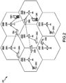
- Figure 2 illustrates an example of a wireless communications system 290 that supports a plurality of users.
- reference numerals 292A to 292G refer to cells
- reference numerals 298A to 298G refer to base stations (BS) or base transceiver station (BTS)
- reference numerals 296A to 296J refer to access User Equipments (UE).
- Cell size may vary. Any of a variety of algorithms and methods may be used to schedule transmissions in system 290.
- System 290 provides communication for a number of cells 292A through 292G, each of which is serviced by a corresponding base station 298A through 298G, respectively.
- the present disclosure proposes a technique by which a very large number of mobile terminals, also known as mobile devices, may be attached to a wireless network in a network initiated manner.
- the mobile devices maintain very low duty cycle traffic and are mostly stationary.
- a technique disclosed in the present disclosure employs a single attachment step, the establishment of a long term identifier (LTID) for the mobile device, and the storage of the coverage area, or set of sectors, in which the mobile device is located. Subsequently, the mobile device can completely detach itself from the wireless network and begin listening to paging indicators which are positioned in time slots, or time instances, that are a function of the LTID.
- LTID long term identifier
- the present disclosure describes a process for initiating the attachment of a mobile device from the wireless network side. Also disclosed is a mechanism for paging of mobile devices that are currently not registered in a radio access network or a core network of a wireless network.
- a potential advantage is that a large number of very low duty cycle mobile devices may be connected to a wireless network whenever the wireless network detects a need for data transfer between the mobile device and the wireless network.
- M2M machine-to-machine
- M2M devices mobile devices used for M2M applications are known as M2M devices. Examples for such applications include smart meters, building monitoring and safety systems, smart vending machines, eHealth for disease management, remote monitoring of industrial machines or installations or M2M applications that rely on battery powered mobile devices without frequent recharging.
- M2M devices need to stay connected, for example attach to the wireless network once and stay attached, for extended periods of time, it may be too costly or even impossible in wireless systems due to the very large number of connections (i.e. attached mobile devices) that need to be maintained.
- the mobile device, or M2M device may need to operate at an extremely low duty cycle to ensure a very long battery life.
- the wireless network itself could initiate an attachment of a specific M2M device or a group of M2M devices when there is need to exchange information with the addressed M2M device or group of M2M devices.
- a M2M application running on the wireless network side or a M2M application running on a M2M device needs to communicate with another M2M device or a group of M2M devices, the wireless network could then initiate an attachment of the requested M2M devices without need to stay connected all the time.
- a wireless network-initiated attachment procedure may work with M2M devices that are not registered in the wireless network. Therefore, in one example, a registration-less paging method would enable an efficient use of wireless network-initiated attachment procedures.
- possible bottlenecks may include one or more of the following:
- one way of servicing many low duty cycle M2M devices performs some form of a low duty cycle registration procedure, which may, in one example, follow one or more of the following steps:
- a low duty cycle registration procedure may have negative impacts. From a wireless network side, negative impacts may result if many M2M devices are performing the low duty cycle registration procedure which results in a fairly large overhead for the actual registration procedure compared to the polling step. For example, the processing required for the registration on the wireless network side may be much more than the actual processing for the polling of the server. For example, if the M2M device just wants to ask the server "Is there something for me?", the server should simply answer with a "yes" or "no". This example results in a small amount of information compared to what is transferred and processed for a full registration, setting up of a connection, etc.
- the polling interval may be dimensioned to be significantly shorter than the expected time between events that would trigger the need for data transfer. For example, it may be assumed that less than half of the polls may actually result in some data exchange. If a very large number of M2M devices perform this type of low duty cycle registration procedure, a large waste of capacity may result.
- the device may need to perform expensive procedures, such as attach, even when there is no data traffic.
- expensive procedures such as attach
- the battery impact for each of the attach cycles would be much more significant than an appropriate paging.
- Entity to Poll if there is not a single server or a central service layer for determining whether there is a need for action (e.g., transfer of information), it may be difficult to determine which location is the right point to poll. For example, there may be multiple potential entities that a M2M device would have to poll in case it goes through periodic low duty cycle registration.
- one solution to this need may include a wireless network-initiated attach procedure associated with a registration-less paging.
- registration-less paging refers to paging a mobile terminal, e.g. M2M device, which is not registered in a wireless network. For example, no registration in the wireless network results in the wireless network not having any context information about the mobile terminal.
- Context information may be location information about the mobile terminal, which may be used to find the mobile terminal as needed for paging.
- an outside user for example a server application connected to the Internet or a middleware platform, may request a page of a wireless terminal at a specific area.
- Registration-less paging of the mobile terminal may include a pre-defined rule for a listen time when the mobile terminal should listen to such paging requests. In one example, the mobile terminal wakes up at the listen time to receive the paging request.
- FIG 3 illustrates an example of a high level M2M architecture with several attached M2M devices.
- a high level M2M architecture uses a M2M service layer on the wireless network side to communicate with a core network of a wireless system as illustrated in Figure 3 .
- a number of M2M applications (shown on top in Figure 3 ) communicate with a M2M service layer (shown as a box below the M2M applications) to provide functionality to exchange information with M2M devices (shown at the bottom in Figure 3 ).
- M2M devices use a wireless wide area network (WWAN) to connect to the M2M service layer
- WWAN wireless wide area network
- a M2M application sitting on top of the M2M service layer or a M2M application running on one of the M2M devices may request the M2M service layer to establish an exchange of information between the requesting M2M application and a specific M2M device or a group of M2M devices.
- the M2M service layer may contact the core network of the underlying wireless network, e.g., WWAN, to connect to the addressed M2M device. For example, if the M2M device is currently not attached to the network, it would establish the attachment. For example, if the addressed M2M device is not registered to the WWAN, it may use a paging mechanism to get hold of the requested M2M device.
- WWAN wireless wide area network
- the wireless network-initiated attach procedure may be triggered by a special message from the M2M service layer on the wireless network side or by a normal domain name system (DNS) query.
- DNS domain name system
- the wireless network does not have the normal context information for the M2M device which is addressed by the M2M service layer and therefore a special paging message may be introduced.
- the wireless network-initiated attach procedure may operate as follows:
- the disclosed approach allows reducing the context that needs to be kept by the wireless network for an M2M device which is not registered to the wireless network to almost zero, beside the allocation of the fully qualified domain name (FQDN) or long term identifier (LTID) plus the cell or group of cells in which the paging needs to occur.
- FQDN fully qualified domain name
- LTID long term identifier
- the wireless network-initiated attach procedure may also use the existing paging mechanisms for devices that are already registered but not attached.
- the disclosed approach contains a new paging mechanism which may be used to page M2M devices that are currently not registered in the wireless network, but for which a long term ID (LTID) has been established already.
- the disclosed approach may be coupled with the flexibility to allow for very long paging cycles to enable long battery life on the M2M device side.
- a registration-less paging procedure may include one or more of the following steps:
- the proposed solutions are also applicable to M2M systems which do not use a M2M service layer.
- the proposed solutions could also be used in M2M systems where a M2M server desires to reach a M2M device through the wireless network, e.g., WWAN.
- the M2M server would just need to be able to send a request for a wireless network-initiated attach from the core network of the wireless network.
- the concept could also be extended to initiating attachment of groups of M2M devices by the wireless network.
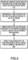
- Figure 4 illustrates a first example of a flow diagram for registration-less paging.
- M2M machine-to-machine
- the mobile device detects a valid page for the identified mobile device during the determined time instance.
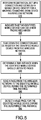
- Figure 5 illustrates a second example of a flow diagram for registration-less paging.
- block 510 perform registration, set up a connection and establish a mobile device identity for a machine-to-machine (M2M) device in a wireless network.
- M2M machine-to-machine
- the connection is set up with a M2M service layer.
- the device identity for a M2M device i.e., M2M device identity
- LTID long term ID
- the identified mobile device can use a new paging mechanism.
- the indication is made to a core network within the wireless network.
- block 530 tear down the connection and de-register the identified mobile device from the wireless network.
- a time instance when the identified mobile device should listen to pages In one example, more than one time instance is determined. In one example, the determination uses the LTID of the M2M device. In block 550, send a page from the wireless network to the identified mobile device during the determined time instance. In one example, the determined time instance is based on the LTID. In one aspect, in block 560, the mobile device detects a valid page for the identified mobile device during the determined time instance. In one example, the detecting the valid page also includes receiving paging data, such as, user data or special data which triggers further action. For example, the special data may be a command which initiates a regular attach procedure from the M2M device side.
- the special data may be a command which initiates a regular attach procedure from the M2M device side.
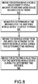
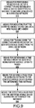
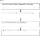
- Figure 6 illustrates an example of a flow diagram for a network-initiated attach procedure.
- receive a request to attach a mobile device in a wireless network In one example, the mobile device is a M2M device.
- the request arrives at a paging agent on a core network side.
- the request arrives through a M2M service layer or through a domain name system (DNS) system.
- the paging agent is a serving GPRS support node (SGSN) or mobile management entity (MME).
- SGSN serving GPRS support node
- MME mobile management entity
- generate a paging message based on the request to attach the mobile device.
- the paging message includes a long term ID (LTID).
- LTID long term ID
- the LTID is not allocated by the wireless network itself.
- the LTID is allocated as a fully qualified domain name (FQDN) or a long term ID (LTID) which was established during a first contact between the mobile device and service layer.
- more than one paging indicator is sent.
- one or more paging indicator is sent during one or more time instances.
- the agreed rule is based on the FQDN or on the LTID.
- the attach procedure is triggered by detection of the paging indicators.
- the processing units may be implemented within one or more application specific integrated circuits (ASICs), digital signal processors (DSPs), digital signal processing devices (DSPDs), programmable logic devices (PLDs), field programmable gate arrays (FPGAs), processors, controllers, micro-controllers, microprocessors, other electronic units designed to perform the functions described therein, or a combination thereof.
- ASICs application specific integrated circuits
- DSPs digital signal processors
- DSPDs digital signal processing devices
- PLDs programmable logic devices
- FPGAs field programmable gate arrays
- processors controllers, micro-controllers, microprocessors, other electronic units designed to perform the functions described therein, or a combination thereof.
- the implementation may be through modules (e.g., procedures, functions, etc.) that perform the functions described therein.
- the software codes may be stored in memory units and executed by a processor unit.
- the steps or functions described herein may be implemented in hardware, software, firmware, or any combination thereof. If implemented in software, the functions may be stored on or transmitted over as one or more instructions or code on a computer-readable medium.
- Computer-readable media includes both computer storage media and communication media including any medium that facilitates transfer of a computer program from one place to another.
- a storage media may be any available media that can be accessed by a computer.
- such computer-readable media can comprise RAM, ROM, EEPROM, CD-ROM or other optical disk storage, magnetic disk storage or other magnetic storage devices, or any other medium that can be used to carry or store desired program code in the form of instructions or data structures and that can be accessed by a computer.
- any connection is properly termed a computer-readable medium.
- the software is transmitted from a website, server, or other remote source using a coaxial cable, fiber optic cable, twisted pair, digital subscriber line (DSL), or wireless technologies such as infrared, radio, and microwave
- the coaxial cable, fiber optic cable, twisted pair, DSL, or wireless technologies such as infrared, radio, and microwave are included in the definition of medium.
- Disk and disc includes compact disc (CD), laser disc, optical disc, digital versatile disc (DVD), floppy disk and blu-ray disc where disks usually reproduce data magnetically, while discs reproduce data optically with lasers. Combinations of the above should also be included within the scope of computer-readable media.
- a processor is coupled with a memory which stores data, metadata, program instructions, etc. to be executed by the processor for implementing or performing the various flow diagrams, logical blocks and/or modules described herein.
- Figure 7 illustrates an example of a device 700 comprising a processor 710 in communication with a memory 720 for executing the processes for registration-less paging.
- the device 700 is also for executing the processes for a network-initiated attach procedure.
- the device 700 is used to implement the algorithms illustrated in Figures 4 , 5 , 6 and 11 .
- the memory 720 is located within the processor 710.
- the memory 720 is external to the processor 710.
- the processor includes circuitry for implementing or performing the various flow diagrams, logical blocks and/or modules described herein.
- Figure 8 illustrates a first example of a device 800 suitable for registration-less paging.
- the device 800 is implemented by at least one processor comprising one or more modules configured to provide different aspects of registration-less paging as described herein in blocks 810, 820, 830 and 840.
- each module comprises hardware, firmware, software, or any combination thereof.
- the device 800 is also implemented by at least one memory in communication with the at least one processor.
- Figure 9 illustrates a second example of a device 900 suitable for registration-less paging.
- the device 900 is implemented by at least one processor comprising one or more modules configured to provide different aspects of registration-less paging as described herein in blocks 910, 920, 930, 940, 950 and 960.
- each module comprises hardware, firmware, software, or any combination thereof.
- the device 900 is also implemented by at least one memory in communication with the at least one processor.
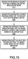
- Figure 10 illustrates an example of a device 1000 suitable for a network-initiated attach procedure.
- the device 1000 is implemented by at least one processor comprising one or more modules configured to provide different aspects of a network-initiated attach procedure as described herein in blocks 1010, 1020, 1030 and 1040.
- each module comprises hardware, firmware, software, or any combination thereof.
- the device 1000 is also implemented by at least one memory in communication with the at least one processor.
- Figure 11 illustrates an example of a flow diagram for registration-less paging from a mobile device perspective.
- establish a mobile device identity for a mobile device in a wireless network In block 1110, establish a mobile device identity for a mobile device in a wireless network.
- receive a valid page during the determined time instance In block 1140, start an attach procedure based on the received valid page. In one aspect, the step in block 1140 is optional.
- Figure 12 illustrates an example of device 1200 for implementing registration-less paging from a mobile device perspective.
- the device 1200 is implemented by at least one processor comprising one or more modules configured to provide registration-less paging from a mobile device perspective as described herein in blocks 1210, 1220, 1230 and 1240.
- each module comprises hardware, firmware, software, or any combination thereof.
- the device 1200 is also implemented by at least one memory in communication with the at least one processor.
Landscapes
- Engineering & Computer Science (AREA)
- Computer Networks & Wireless Communication (AREA)
- Signal Processing (AREA)
- Mobile Radio Communication Systems (AREA)
- Telephonic Communication Services (AREA)
Applications Claiming Priority (3)
| Application Number | Priority Date | Filing Date | Title |
|---|---|---|---|
| US28581009P | 2009-12-11 | 2009-12-11 | |
| US12/965,681 US10251146B2 (en) | 2009-12-11 | 2010-12-10 | Apparatus and method for network-initiated attachment and registration-less paging |
| PCT/US2010/060136 WO2011072303A1 (en) | 2009-12-11 | 2010-12-13 | Apparatus and method for network- initiated attachment and registration- less paging in a wireless network |
Publications (2)
| Publication Number | Publication Date |
|---|---|
| EP2510730A1 EP2510730A1 (en) | 2012-10-17 |
| EP2510730B1 true EP2510730B1 (en) | 2018-12-05 |
Family
ID=44142268
Family Applications (1)
| Application Number | Title | Priority Date | Filing Date |
|---|---|---|---|
| EP10796236.7A Active EP2510730B1 (en) | 2009-12-11 | 2010-12-13 | Apparatus and method for network-initiated attachment and registration-less paging in a wireless network |
Country Status (8)
| Country | Link |
|---|---|
| US (1) | US10251146B2 (ja) |
| EP (1) | EP2510730B1 (ja) |
| JP (2) | JP2013514015A (ja) |
| KR (1) | KR101383871B1 (ja) |
| CN (2) | CN102652450B (ja) |
| BR (1) | BR112012013833B1 (ja) |
| TW (1) | TWI441545B (ja) |
| WO (1) | WO2011072303A1 (ja) |
Families Citing this family (37)
| Publication number | Priority date | Publication date | Assignee | Title |
|---|---|---|---|---|
| EP2384592A1 (en) * | 2009-01-05 | 2011-11-09 | Nokia Siemens Networks Oy | Determining an optimized configuration of a telecommunication network |
| US20110310731A1 (en) * | 2010-06-18 | 2011-12-22 | Sharp Laboratories Of America, Inc. | Controlling network resource usage of machine type communication (mtc) devices |
| US10171286B2 (en) * | 2011-03-03 | 2019-01-01 | Iot Holdings, Inc. | Method and apparatus for accessing services affiliated with a discovered service provider |
| EP2727305A4 (en) | 2011-07-01 | 2015-01-07 | Intel Corp | LAYER SHIFTING IN MULTIPLE INPUT COMMUNICATIONS, MULTIPLE OPEN LOOP OUTPUTS |
| EP2544467B1 (en) * | 2011-07-04 | 2018-12-19 | Koninklijke KPN N.V. | Triggering with time indicator |
| TWI459777B (zh) * | 2011-07-11 | 2014-11-01 | Mediatek Inc | 加強型傳呼的方法及其機器類型通訊裝置 |
| GB2493348A (en) * | 2011-07-29 | 2013-02-06 | Intellectual Ventures Holding 81 Llc | Mobile communications terminal with simplified handover |
| US8244244B1 (en) | 2011-08-31 | 2012-08-14 | Renesas Mobile Corporation | Method for triggering a user equipment |
| GB2486753B (en) * | 2011-08-31 | 2013-09-04 | Renesas Mobile Corp | Method, apparatus and system for detaching and triggering user equipement |
| WO2013030774A1 (en) * | 2011-08-31 | 2013-03-07 | Renesas Mobile Corporation | Method, apparatus and system for detaching and triggering user equipment |
| JP5944004B2 (ja) | 2011-10-03 | 2016-07-05 | インテル・コーポレーション | デバイスツーデバイス通信(d2d通信)メカニズム |
| US8942698B2 (en) | 2011-11-02 | 2015-01-27 | Qualcomm Incorporated | Methods and devices for facilitating access terminal registration with a registration server |
| US8565160B2 (en) | 2011-11-02 | 2013-10-22 | Qualcomm Incorporated | Methods and devices for facilitating access terminal registrations |
| US9241351B2 (en) * | 2011-11-04 | 2016-01-19 | Intel Corporation | Techniques and configurations for triggering a plurality of wireless devices |
| GB2496179B (en) * | 2011-11-04 | 2014-01-22 | Renesas Mobile Corp | Reducing signaling Overhead in Wireless Communications Networks |
| WO2013065027A1 (en) * | 2011-11-04 | 2013-05-10 | Renesas Mobile Corporation | Controlling detach and detach time of a machine -type communication device for saving signaling and reducing storage of registration information |
| WO2013074849A1 (en) * | 2011-11-15 | 2013-05-23 | Zte (Usa) Inc. | Triggering machine-to-machine device communication in wireless networks |
| US9497102B2 (en) | 2011-12-06 | 2016-11-15 | Qualcomm Incorporated | Systems and methods for machine to machine device control and triggering |
| CN102421190A (zh) * | 2012-01-04 | 2012-04-18 | 大唐移动通信设备有限公司 | 一种mtc设备的寻呼方法和设备 |
| US10271274B2 (en) | 2012-02-03 | 2019-04-23 | Qualcomm Incorporated | Devices and methods for facilitating extended time periods for maintaining PPP sessions |
| US9185649B2 (en) | 2012-03-30 | 2015-11-10 | Qualcomm Incorporated | High-speed data channel availability |
| WO2013164247A2 (en) * | 2012-04-30 | 2013-11-07 | Nokia Siemens Networks Oy | Method to introduce a state in a device for reachability when the device is not attached |
| EP2893720A1 (en) * | 2012-09-10 | 2015-07-15 | Telefonaktiebolaget L M Ericsson (PUBL) | Method and system for communication between machine to machine m2m service provider networks |
| EP2892254B1 (en) * | 2012-09-21 | 2018-11-28 | Huawei Technologies Co., Ltd. | Method and device for transmitting public message |
| US9973879B2 (en) * | 2012-11-26 | 2018-05-15 | Qualcomm Incorporated | Opportunistic decoding of transmissions on a forward link in a machine-to-machine wireless wide area network |
| US9226289B2 (en) * | 2012-12-18 | 2015-12-29 | Qualcomm Incorporated | Systems and methods to conserve power of machine-to-machine devices using a shared data channel |
| US9292077B2 (en) | 2013-01-04 | 2016-03-22 | Qualcomm Incorporated | Methods and apparatus for efficient service layer assistance for modem sleep operations |
| CN103945497B (zh) * | 2013-01-18 | 2018-01-23 | 中兴通讯股份有限公司 | 终端直达通信中发现信号的发送方法、通信终端及系统 |
| US9338762B2 (en) * | 2013-04-29 | 2016-05-10 | Telefonaktiebolaget Lm Ericsson (Publ) | Extended monitoring window for robust paging |
| EP3557894B1 (en) | 2013-05-06 | 2023-12-27 | Convida Wireless, LLC | Device triggering |
| WO2014181941A1 (ko) * | 2013-05-09 | 2014-11-13 | 전자부품연구원 | 개방형 m2m 시스템 및 그의 리소스 관리와 인터페이스 방법 |
| JP6201728B2 (ja) * | 2013-12-20 | 2017-09-27 | カシオ計算機株式会社 | 通信システム、通信端末、プログラム、通信端末の情報問い合わせ方法及び情報提供方法 |
| EP3167630B1 (en) * | 2014-07-07 | 2024-05-22 | InterDigital Patent Holdings, Inc. | Coordinated grouping for machine type communications group based services |
| EP3672336B1 (en) * | 2014-08-27 | 2021-07-21 | Huawei Technologies Co., Ltd. | Access network node, core network node, and paging method |
| WO2018057601A1 (en) * | 2016-09-20 | 2018-03-29 | Convida Wireless, Llc | Service layer support for multiple interface nodes |
| CN110169029B (zh) * | 2017-01-04 | 2021-11-26 | 瑞典爱立信有限公司 | 用于在无线通信系统中进行寻呼的方法和网络节点 |
| WO2021064286A1 (en) * | 2019-09-30 | 2021-04-08 | Nokia Technologies Oy | Method, apparatus and computer program product for adaptive paging of user equipment supporting multiple subscriber identification modules |
Citations (1)
| Publication number | Priority date | Publication date | Assignee | Title |
|---|---|---|---|---|
| US20050064880A1 (en) * | 1997-05-30 | 2005-03-24 | Butler Brian K. | Dual event slotted paging |
Family Cites Families (28)
| Publication number | Priority date | Publication date | Assignee | Title |
|---|---|---|---|---|
| JPS63109620A (ja) | 1986-10-27 | 1988-05-14 | Nec Corp | 無線選択呼出しシステム |
| JPH0697877A (ja) | 1992-09-10 | 1994-04-08 | Toshiba Corp | 移動無線通信装置 |
| US5603081A (en) * | 1993-11-01 | 1997-02-11 | Telefonaktiebolaget Lm Ericsson | Method for communicating in a wireless communication system |
| AU2263599A (en) | 1997-11-24 | 1999-06-15 | Mannesmann Aktiengesellschaft | Method for receiving and processing information emitted from a central station to a plurality of non-defined subscribers by a terminal and a terminal for carrying out the method |
| US6308060B2 (en) * | 1998-06-15 | 2001-10-23 | @Track Communications, Inc. | Method and apparatus for providing a communication path using a paging network |
| US6438375B1 (en) * | 1999-03-04 | 2002-08-20 | Telefonaktiebolaget Lm Ericsson (Publ) | Coordinating different types of messages sent to mobile radios in a mobile communications system |
| FI109865B (fi) * | 1999-12-08 | 2002-10-15 | Nokia Corp | Menetelmä langattoman viestimen tehonkulutuksen pienentämiseksi |
| JP2001309069A (ja) | 2000-04-26 | 2001-11-02 | Ricoh Elemex Corp | ページャにより起動する無線検針システム |
| GB2365257B (en) * | 2000-07-28 | 2003-03-12 | Data Information Systems Ltd | Telephone status/availability system |
| JP2002314475A (ja) | 2000-10-23 | 2002-10-25 | Yozan Inc | 無線通信装置、無線通信システムおよび通信装置 |
| KR100464351B1 (ko) * | 2001-10-20 | 2005-01-03 | 삼성전자주식회사 | 비동기 부호분할다중접속 통신시스템의 멀티미디어브로드캐스팅, 멀티캐스팅 방식에 있어서 추가적인반송파의 사용시에 적용 가능한 페이징 방법 및 장치 |
| JP2004129905A (ja) | 2002-10-11 | 2004-04-30 | Yozan Inc | 身体情報管理システム、身体情報管理方法および無線通信装置 |
| US7873015B2 (en) * | 2002-10-18 | 2011-01-18 | Kineto Wireless, Inc. | Method and system for registering an unlicensed mobile access subscriber with a network controller |
| GB0307764D0 (en) * | 2003-04-03 | 2003-05-07 | Nokia Corp | Push service location using virtual indentification of predictable temporal announcements |
| US8073470B1 (en) * | 2005-01-31 | 2011-12-06 | Jasper Wireless, Inc | Paging windows for power conservation in wireless networks |
| US7860527B2 (en) * | 2005-05-12 | 2010-12-28 | Qualcomm Incorporated | Method and apparatus for receiving data and paging from multiple wireless communication systems |
| US8519847B2 (en) * | 2005-11-24 | 2013-08-27 | Nokia Corporation | Methodology, module, terminal, and system enabling scheduled operation of a radio frequency identification (RFID) subsystem and a wireless communication subsystem |
| EP1850618A1 (en) | 2006-04-28 | 2007-10-31 | Alcatel Lucent | A method for access by a mobile station to a core network via an unlicensed mobile access network |
| US20070254677A1 (en) * | 2006-05-01 | 2007-11-01 | Motorola, Inc. | Method and system to enable paging for mobile ip nodes |
| KR101208525B1 (ko) * | 2006-06-05 | 2012-12-05 | 엘지전자 주식회사 | 유휴모드 전환 제어 방법 |
| US7826858B2 (en) * | 2006-07-12 | 2010-11-02 | Intel Corporation | Protected paging indication mechanism within wireless networks |
| EP2081396B1 (en) * | 2006-11-03 | 2012-12-12 | Huawei Technologies Co., Ltd. | Mobile communication method and access entity |
| US7774008B2 (en) * | 2006-12-22 | 2010-08-10 | Cellco Partnership | MDN-less SMS messaging (network solution) for wireless M2M application |
| CN103763775B (zh) | 2007-12-17 | 2017-04-12 | Tcl通讯科技控股有限公司 | 移动通信系统 |
| WO2010059813A1 (en) * | 2008-11-21 | 2010-05-27 | Interdigital Patent Holdings, Inc. | Method and apparatus for supporting aggregation of multiple component carriers |
| KR101022578B1 (ko) | 2009-01-06 | 2011-03-16 | 엘지전자 주식회사 | 무선통신 시스템에서 페이징 메시지 전송과정을 수행하는 방법 |
| GB2471118A (en) | 2009-06-17 | 2010-12-22 | Simsmart Ltd | Method and apparatus for a wireless device to monitor a short message cell broadcast channel whilst detached from the network |
| US8935428B2 (en) * | 2009-06-24 | 2015-01-13 | Broadcom Corporation | Fault tolerance approaches for DNS server failures |
-
2010
- 2010-12-10 US US12/965,681 patent/US10251146B2/en active Active
- 2010-12-13 CN CN201080056116.7A patent/CN102652450B/zh active Active
- 2010-12-13 TW TW099143505A patent/TWI441545B/zh not_active IP Right Cessation
- 2010-12-13 EP EP10796236.7A patent/EP2510730B1/en active Active
- 2010-12-13 CN CN201510191012.1A patent/CN104869528B/zh active Active
- 2010-12-13 WO PCT/US2010/060136 patent/WO2011072303A1/en active Application Filing
- 2010-12-13 BR BR112012013833-2A patent/BR112012013833B1/pt not_active IP Right Cessation
- 2010-12-13 JP JP2012543334A patent/JP2013514015A/ja not_active Withdrawn
- 2010-12-13 KR KR1020127017963A patent/KR101383871B1/ko active IP Right Grant
-
2014
- 2014-07-11 JP JP2014143372A patent/JP5937149B2/ja not_active Expired - Fee Related
Patent Citations (1)
| Publication number | Priority date | Publication date | Assignee | Title |
|---|---|---|---|---|
| US20050064880A1 (en) * | 1997-05-30 | 2005-03-24 | Butler Brian K. | Dual event slotted paging |
Also Published As
| Publication number | Publication date |
|---|---|
| US20110140846A1 (en) | 2011-06-16 |
| JP2013514015A (ja) | 2013-04-22 |
| CN102652450A (zh) | 2012-08-29 |
| BR112012013833B1 (pt) | 2021-07-06 |
| KR101383871B1 (ko) | 2014-04-10 |
| TW201141281A (en) | 2011-11-16 |
| CN102652450B (zh) | 2015-09-09 |
| CN104869528A (zh) | 2015-08-26 |
| BR112012013833A8 (pt) | 2021-01-05 |
| CN104869528B (zh) | 2018-10-02 |
| JP2014222931A (ja) | 2014-11-27 |
| TWI441545B (zh) | 2014-06-11 |
| BR112012013833A2 (pt) | 2020-11-03 |
| KR20120105025A (ko) | 2012-09-24 |
| JP5937149B2 (ja) | 2016-06-22 |
| EP2510730A1 (en) | 2012-10-17 |
| US10251146B2 (en) | 2019-04-02 |
| WO2011072303A1 (en) | 2011-06-16 |
Similar Documents
| Publication | Publication Date | Title |
|---|---|---|
| EP2510730B1 (en) | Apparatus and method for network-initiated attachment and registration-less paging in a wireless network | |
| EP3284303B1 (en) | Method and apparatus for performing extended drx operation based on uplink indication in wireless communication system | |
| EP2991411B1 (en) | Method for supporting power saving mode and radio device therefor | |
| EP3905838A1 (en) | Method and device for by-link activation and deactivation for reducing power consumption in next generation mobile communication system | |
| JP6084979B2 (ja) | 通信端末、方法およびプログラム | |
| US8953477B2 (en) | Method of receiving and transmitting message in a mobile communication system using a MTC device and apparatus for the same | |
| US11777695B2 (en) | Method and apparatus for managing dormant bandwidth part in next-generation mobile communication system | |
| AU2011214925B2 (en) | Method and arrangement in a telecommunication system | |
| EP3096566B1 (en) | Method for supporting power saving mode and wireless device thereof | |
| KR20090029623A (ko) | 무선통신 시스템에서 시스템 정보 획득 방법 | |
| US10342065B2 (en) | Method and apparatus for operating at cell not supporting extended DRX in wireless communication system | |
| US20220052829A1 (en) | Method and apparatus for activating and reactivating scell considering currently activated bandwidth part and bandwidth part configuration information in next-generation mobile communication system | |
| CN104519550A (zh) | 一种发现d2d设备的方法、装置及系统 | |
| US20230122848A1 (en) | Phr triggering method accommodating dormant portion of bandwidth in next-generation mobile communication system, and phr configuration method and device | |
| CN111567135B (zh) | 通信方法、通信装置 | |
| EP2157807B1 (en) | Method of network controller reporting on the cycle period ability of the maximal discontinuous transmission in a cell | |
| EP3300437B1 (en) | Paging for downlink data transfer in connectionless mode in a mobile system | |
| WO2009129750A1 (zh) | 传递信道信息及功率控制的方法及装置 | |
| GB2495282A (en) | A communication terminal detaches from a high bandwidth interface and reattaches to a low bandwidth interface |
Legal Events
| Date | Code | Title | Description |
|---|---|---|---|
| PUAI | Public reference made under article 153(3) epc to a published international application that has entered the european phase |
Free format text: ORIGINAL CODE: 0009012 |
|
| 17P | Request for examination filed |
Effective date: 20120704 |
|
| AK | Designated contracting states |
Kind code of ref document: A1 Designated state(s): AL AT BE BG CH CY CZ DE DK EE ES FI FR GB GR HR HU IE IS IT LI LT LU LV MC MK MT NL NO PL PT RO RS SE SI SK SM TR |
|
| DAX | Request for extension of the european patent (deleted) | ||
| STAA | Information on the status of an ep patent application or granted ep patent |
Free format text: STATUS: EXAMINATION IS IN PROGRESS |
|
| 17Q | First examination report despatched |
Effective date: 20170117 |
|
| GRAP | Despatch of communication of intention to grant a patent |
Free format text: ORIGINAL CODE: EPIDOSNIGR1 |
|
| STAA | Information on the status of an ep patent application or granted ep patent |
Free format text: STATUS: GRANT OF PATENT IS INTENDED |
|
| INTG | Intention to grant announced |
Effective date: 20180613 |
|
| GRAS | Grant fee paid |
Free format text: ORIGINAL CODE: EPIDOSNIGR3 |
|
| GRAA | (expected) grant |
Free format text: ORIGINAL CODE: 0009210 |
|
| GRAA | (expected) grant |
Free format text: ORIGINAL CODE: 0009210 |
|
| STAA | Information on the status of an ep patent application or granted ep patent |
Free format text: STATUS: THE PATENT HAS BEEN GRANTED |
|
| AK | Designated contracting states |
Kind code of ref document: B1 Designated state(s): AL AT BE BG CH CY CZ DE DK EE ES FI FR GB GR HR HU IE IS IT LI LT LU LV MC MK MT NL NO PL PT RO RS SE SI SK SM TR |
|
| REG | Reference to a national code |
Ref country code: GB Ref legal event code: FG4D |
|
| REG | Reference to a national code |
Ref country code: CH Ref legal event code: EP |
|
| REG | Reference to a national code |
Ref country code: AT Ref legal event code: REF Ref document number: 1074687 Country of ref document: AT Kind code of ref document: T Effective date: 20181215 |
|
| REG | Reference to a national code |
Ref country code: IE Ref legal event code: FG4D |
|
| REG | Reference to a national code |
Ref country code: DE Ref legal event code: R096 Ref document number: 602010055646 Country of ref document: DE |
|
| REG | Reference to a national code |
Ref country code: NL Ref legal event code: MP Effective date: 20181205 |
|
| REG | Reference to a national code |
Ref country code: AT Ref legal event code: MK05 Ref document number: 1074687 Country of ref document: AT Kind code of ref document: T Effective date: 20181205 |
|
| REG | Reference to a national code |
Ref country code: LT Ref legal event code: MG4D |
|
| PG25 | Lapsed in a contracting state [announced via postgrant information from national office to epo] |
Ref country code: LV Free format text: LAPSE BECAUSE OF FAILURE TO SUBMIT A TRANSLATION OF THE DESCRIPTION OR TO PAY THE FEE WITHIN THE PRESCRIBED TIME-LIMIT Effective date: 20181205 Ref country code: AT Free format text: LAPSE BECAUSE OF FAILURE TO SUBMIT A TRANSLATION OF THE DESCRIPTION OR TO PAY THE FEE WITHIN THE PRESCRIBED TIME-LIMIT Effective date: 20181205 Ref country code: HR Free format text: LAPSE BECAUSE OF FAILURE TO SUBMIT A TRANSLATION OF THE DESCRIPTION OR TO PAY THE FEE WITHIN THE PRESCRIBED TIME-LIMIT Effective date: 20181205 Ref country code: NO Free format text: LAPSE BECAUSE OF FAILURE TO SUBMIT A TRANSLATION OF THE DESCRIPTION OR TO PAY THE FEE WITHIN THE PRESCRIBED TIME-LIMIT Effective date: 20190305 Ref country code: FI Free format text: LAPSE BECAUSE OF FAILURE TO SUBMIT A TRANSLATION OF THE DESCRIPTION OR TO PAY THE FEE WITHIN THE PRESCRIBED TIME-LIMIT Effective date: 20181205 Ref country code: BG Free format text: LAPSE BECAUSE OF FAILURE TO SUBMIT A TRANSLATION OF THE DESCRIPTION OR TO PAY THE FEE WITHIN THE PRESCRIBED TIME-LIMIT Effective date: 20190305 Ref country code: ES Free format text: LAPSE BECAUSE OF FAILURE TO SUBMIT A TRANSLATION OF THE DESCRIPTION OR TO PAY THE FEE WITHIN THE PRESCRIBED TIME-LIMIT Effective date: 20181205 Ref country code: LT Free format text: LAPSE BECAUSE OF FAILURE TO SUBMIT A TRANSLATION OF THE DESCRIPTION OR TO PAY THE FEE WITHIN THE PRESCRIBED TIME-LIMIT Effective date: 20181205 |
|
| PG25 | Lapsed in a contracting state [announced via postgrant information from national office to epo] |
Ref country code: GR Free format text: LAPSE BECAUSE OF FAILURE TO SUBMIT A TRANSLATION OF THE DESCRIPTION OR TO PAY THE FEE WITHIN THE PRESCRIBED TIME-LIMIT Effective date: 20190306 Ref country code: AL Free format text: LAPSE BECAUSE OF FAILURE TO SUBMIT A TRANSLATION OF THE DESCRIPTION OR TO PAY THE FEE WITHIN THE PRESCRIBED TIME-LIMIT Effective date: 20181205 Ref country code: SE Free format text: LAPSE BECAUSE OF FAILURE TO SUBMIT A TRANSLATION OF THE DESCRIPTION OR TO PAY THE FEE WITHIN THE PRESCRIBED TIME-LIMIT Effective date: 20181205 Ref country code: RS Free format text: LAPSE BECAUSE OF FAILURE TO SUBMIT A TRANSLATION OF THE DESCRIPTION OR TO PAY THE FEE WITHIN THE PRESCRIBED TIME-LIMIT Effective date: 20181205 |
|
| PG25 | Lapsed in a contracting state [announced via postgrant information from national office to epo] |
Ref country code: NL Free format text: LAPSE BECAUSE OF FAILURE TO SUBMIT A TRANSLATION OF THE DESCRIPTION OR TO PAY THE FEE WITHIN THE PRESCRIBED TIME-LIMIT Effective date: 20181205 |
|
| PG25 | Lapsed in a contracting state [announced via postgrant information from national office to epo] |
Ref country code: PL Free format text: LAPSE BECAUSE OF FAILURE TO SUBMIT A TRANSLATION OF THE DESCRIPTION OR TO PAY THE FEE WITHIN THE PRESCRIBED TIME-LIMIT Effective date: 20181205 Ref country code: IT Free format text: LAPSE BECAUSE OF FAILURE TO SUBMIT A TRANSLATION OF THE DESCRIPTION OR TO PAY THE FEE WITHIN THE PRESCRIBED TIME-LIMIT Effective date: 20181205 Ref country code: CZ Free format text: LAPSE BECAUSE OF FAILURE TO SUBMIT A TRANSLATION OF THE DESCRIPTION OR TO PAY THE FEE WITHIN THE PRESCRIBED TIME-LIMIT Effective date: 20181205 Ref country code: PT Free format text: LAPSE BECAUSE OF FAILURE TO SUBMIT A TRANSLATION OF THE DESCRIPTION OR TO PAY THE FEE WITHIN THE PRESCRIBED TIME-LIMIT Effective date: 20190405 |
|
| REG | Reference to a national code |
Ref country code: CH Ref legal event code: PL |
|
| PG25 | Lapsed in a contracting state [announced via postgrant information from national office to epo] |
Ref country code: RO Free format text: LAPSE BECAUSE OF FAILURE TO SUBMIT A TRANSLATION OF THE DESCRIPTION OR TO PAY THE FEE WITHIN THE PRESCRIBED TIME-LIMIT Effective date: 20181205 Ref country code: SK Free format text: LAPSE BECAUSE OF FAILURE TO SUBMIT A TRANSLATION OF THE DESCRIPTION OR TO PAY THE FEE WITHIN THE PRESCRIBED TIME-LIMIT Effective date: 20181205 Ref country code: IS Free format text: LAPSE BECAUSE OF FAILURE TO SUBMIT A TRANSLATION OF THE DESCRIPTION OR TO PAY THE FEE WITHIN THE PRESCRIBED TIME-LIMIT Effective date: 20190405 Ref country code: SM Free format text: LAPSE BECAUSE OF FAILURE TO SUBMIT A TRANSLATION OF THE DESCRIPTION OR TO PAY THE FEE WITHIN THE PRESCRIBED TIME-LIMIT Effective date: 20181205 Ref country code: EE Free format text: LAPSE BECAUSE OF FAILURE TO SUBMIT A TRANSLATION OF THE DESCRIPTION OR TO PAY THE FEE WITHIN THE PRESCRIBED TIME-LIMIT Effective date: 20181205 Ref country code: LU Free format text: LAPSE BECAUSE OF NON-PAYMENT OF DUE FEES Effective date: 20181213 |
|
| REG | Reference to a national code |
Ref country code: DE Ref legal event code: R097 Ref document number: 602010055646 Country of ref document: DE |
|
| REG | Reference to a national code |
Ref country code: IE Ref legal event code: MM4A |
|
| REG | Reference to a national code |
Ref country code: BE Ref legal event code: MM Effective date: 20181231 |
|
| PLBE | No opposition filed within time limit |
Free format text: ORIGINAL CODE: 0009261 |
|
| STAA | Information on the status of an ep patent application or granted ep patent |
Free format text: STATUS: NO OPPOSITION FILED WITHIN TIME LIMIT |
|
| PG25 | Lapsed in a contracting state [announced via postgrant information from national office to epo] |
Ref country code: SI Free format text: LAPSE BECAUSE OF FAILURE TO SUBMIT A TRANSLATION OF THE DESCRIPTION OR TO PAY THE FEE WITHIN THE PRESCRIBED TIME-LIMIT Effective date: 20181205 Ref country code: MC Free format text: LAPSE BECAUSE OF FAILURE TO SUBMIT A TRANSLATION OF THE DESCRIPTION OR TO PAY THE FEE WITHIN THE PRESCRIBED TIME-LIMIT Effective date: 20181205 Ref country code: IE Free format text: LAPSE BECAUSE OF NON-PAYMENT OF DUE FEES Effective date: 20181213 Ref country code: DK Free format text: LAPSE BECAUSE OF FAILURE TO SUBMIT A TRANSLATION OF THE DESCRIPTION OR TO PAY THE FEE WITHIN THE PRESCRIBED TIME-LIMIT Effective date: 20181205 |
|
| 26N | No opposition filed |
Effective date: 20190906 |
|
| PG25 | Lapsed in a contracting state [announced via postgrant information from national office to epo] |
Ref country code: BE Free format text: LAPSE BECAUSE OF NON-PAYMENT OF DUE FEES Effective date: 20181231 |
|
| PG25 | Lapsed in a contracting state [announced via postgrant information from national office to epo] |
Ref country code: CH Free format text: LAPSE BECAUSE OF NON-PAYMENT OF DUE FEES Effective date: 20181231 Ref country code: LI Free format text: LAPSE BECAUSE OF NON-PAYMENT OF DUE FEES Effective date: 20181231 |
|
| REG | Reference to a national code |
Ref country code: DE Ref legal event code: R082 Ref document number: 602010055646 Country of ref document: DE Representative=s name: BARDEHLE PAGENBERG PARTNERSCHAFT MBB PATENTANW, DE Ref country code: DE Ref legal event code: R081 Ref document number: 602010055646 Country of ref document: DE Owner name: QUALCOMM INCORPORATED, SAN DIEGO, US Free format text: FORMER OWNER: QUALCOMM INC., SAN DIEGO, CALIF., US |
|
| PG25 | Lapsed in a contracting state [announced via postgrant information from national office to epo] |
Ref country code: MT Free format text: LAPSE BECAUSE OF NON-PAYMENT OF DUE FEES Effective date: 20181213 |
|
| PG25 | Lapsed in a contracting state [announced via postgrant information from national office to epo] |
Ref country code: TR Free format text: LAPSE BECAUSE OF FAILURE TO SUBMIT A TRANSLATION OF THE DESCRIPTION OR TO PAY THE FEE WITHIN THE PRESCRIBED TIME-LIMIT Effective date: 20181205 |
|
| PG25 | Lapsed in a contracting state [announced via postgrant information from national office to epo] |
Ref country code: MK Free format text: LAPSE BECAUSE OF NON-PAYMENT OF DUE FEES Effective date: 20181205 Ref country code: HU Free format text: LAPSE BECAUSE OF FAILURE TO SUBMIT A TRANSLATION OF THE DESCRIPTION OR TO PAY THE FEE WITHIN THE PRESCRIBED TIME-LIMIT; INVALID AB INITIO Effective date: 20101213 Ref country code: CY Free format text: LAPSE BECAUSE OF FAILURE TO SUBMIT A TRANSLATION OF THE DESCRIPTION OR TO PAY THE FEE WITHIN THE PRESCRIBED TIME-LIMIT Effective date: 20181205 |
|
| PGFP | Annual fee paid to national office [announced via postgrant information from national office to epo] |
Ref country code: GB Payment date: 20221109 Year of fee payment: 13 Ref country code: FR Payment date: 20221110 Year of fee payment: 13 Ref country code: DE Payment date: 20221109 Year of fee payment: 13 |