EP2510207B1 - Verstelleinrichtung für eine Aufladeeinrichtung, insbesondere für einen Abgasturbolader - Google Patents
Verstelleinrichtung für eine Aufladeeinrichtung, insbesondere für einen Abgasturbolader Download PDFInfo
- Publication number
- EP2510207B1 EP2510207B1 EP10772979.0A EP10772979A EP2510207B1 EP 2510207 B1 EP2510207 B1 EP 2510207B1 EP 10772979 A EP10772979 A EP 10772979A EP 2510207 B1 EP2510207 B1 EP 2510207B1
- Authority
- EP
- European Patent Office
- Prior art keywords
- actuating
- connecting element
- adjusting
- adjusting device
- actuating device
- Prior art date
- Legal status (The legal status is an assumption and is not a legal conclusion. Google has not performed a legal analysis and makes no representation as to the accuracy of the status listed.)
- Active
Links
Images
Classifications
-
- F—MECHANICAL ENGINEERING; LIGHTING; HEATING; WEAPONS; BLASTING
- F01—MACHINES OR ENGINES IN GENERAL; ENGINE PLANTS IN GENERAL; STEAM ENGINES
- F01D—NON-POSITIVE DISPLACEMENT MACHINES OR ENGINES, e.g. STEAM TURBINES
- F01D17/00—Regulating or controlling by varying flow
- F01D17/10—Final actuators
- F01D17/12—Final actuators arranged in stator parts
- F01D17/14—Final actuators arranged in stator parts varying effective cross-sectional area of nozzles or guide conduits
- F01D17/16—Final actuators arranged in stator parts varying effective cross-sectional area of nozzles or guide conduits by means of nozzle vanes
- F01D17/165—Final actuators arranged in stator parts varying effective cross-sectional area of nozzles or guide conduits by means of nozzle vanes for radial flow, i.e. the vanes turning around axes which are essentially parallel to the rotor centre line
-
- F—MECHANICAL ENGINEERING; LIGHTING; HEATING; WEAPONS; BLASTING
- F02—COMBUSTION ENGINES; HOT-GAS OR COMBUSTION-PRODUCT ENGINE PLANTS
- F02C—GAS-TURBINE PLANTS; AIR INTAKES FOR JET-PROPULSION PLANTS; CONTROLLING FUEL SUPPLY IN AIR-BREATHING JET-PROPULSION PLANTS
- F02C6/00—Plural gas-turbine plants; Combinations of gas-turbine plants with other apparatus; Adaptations of gas-turbine plants for special use
- F02C6/04—Gas-turbine plants providing heated or pressurised working fluid for other apparatus, e.g. without mechanical power output
- F02C6/10—Gas-turbine plants providing heated or pressurised working fluid for other apparatus, e.g. without mechanical power output supplying working fluid to a user, e.g. a chemical process, which returns working fluid to a turbine of the plant
- F02C6/12—Turbochargers, i.e. plants for augmenting mechanical power output of internal-combustion piston engines by increase of charge pressure
-
- F—MECHANICAL ENGINEERING; LIGHTING; HEATING; WEAPONS; BLASTING
- F05—INDEXING SCHEMES RELATING TO ENGINES OR PUMPS IN VARIOUS SUBCLASSES OF CLASSES F01-F04
- F05D—INDEXING SCHEME FOR ASPECTS RELATING TO NON-POSITIVE-DISPLACEMENT MACHINES OR ENGINES, GAS-TURBINES OR JET-PROPULSION PLANTS
- F05D2220/00—Application
- F05D2220/40—Application in turbochargers
Definitions
- the invention relates to an adjusting device for a charging device, in particular for an exhaust gas turbocharger, the specified in the preamble of claim 1.
- the WO 2007/093407 A1 discloses a turbocharger with variable turbine geometries having a turbine housing with an exhaust gas supply duct, with a turbine rotor rotatably supported in the turbine housing and with a baffle radially outwardly surrounding the turbine rotor having a vane bearing ring having a plurality of vanes, each one a vane shaft mounted in the vane bearing ring, and having an adjusting ring which is operatively connected to the vanes via associated vane levers attached to the vane shafts at one of its ends, each vane lever having at the other end a lever head provided with an associated engagement recess of the adjusting ring can be brought into engagement.
- Each blade lever is constructed asymmetrically and has only on one side of a central portion on an arc segment-shaped bearing nose, which is arranged in the same plane as the lever head.
- WO 2007/134787 A1 shows an adjusting device for an exhaust gas turbocharger, with a retaining ring on which a plurality of vanes is held. Furthermore, an adjusting ring is provided, with the aid of which a movement of the guide vanes can be initiated.
- the adjusting ring is operatively connected via the respective guide vanes associated blade lever, wherein the blade lever is brought into operative connection with the adjusting ring via a perpendicular to the axial direction of the adjusting active surface.
- the turbocharger has undesirably high gap losses, which adversely affects efficient operation of the turbocharger.
- An adjusting device for a charging device, in particular for an exhaust gas turbocharger, with at least one holding element, on which a plurality of guide vanes is held, which via a respective connecting element with an actuating element, in particular an adjusting, operatively engageable and which by means of Actuator are adjustable in their respective angle of attack, characterized in that the respective connecting element with the actuating element via at least one obliquely to the axial direction of the adjusting device extending active surface can be brought into operative connection.
- the adjusting device according to the invention on a much lower wear and thus a low probability of failure, since an uncontrolled movement of the respective connecting element and thus the respective vane is avoided in the axial direction.
- the adjusting device according to the invention offers the possibility to change the guide vanes via the respective connecting element by the actuating element in their respective angle of attack, in order to realize an optimal adaptation of the impeller to flow conditions.
- a very efficient operation of the charging device in a very wide range of operating points for example, one of the supercharger associated internal combustion engine, possible, resulting in low fuel consumption and thus low CO 2 emissions of the internal combustion engine benefits.
- the adjustment of the angle of attack takes place, for example, by a rotation about the axis of rotation of the respective vane, wherein the actuating element via the active surface according to the invention or the Acting surfaces according to the invention cooperates with the connecting element, about which finally the vanes are rotated.
- the connecting element engages in a groove of the actuating element.
- the reverse training for example, wherein the actuating element engages with a corresponding part in a groove of the connecting element.
- a thrust of the respective guide vane in the axial direction can be represented by the oblique effective surface or the oblique active surfaces to achieve the aforementioned advantages.
- an impeller which is designed as a turbine wheel, wherein the respective guide vane is movable by means of the oblique active surface or the oblique active surfaces in the direction of a turbine wheel outlet.
- this oblique formation of the effective area depends on a respective direction of movement of the actuating element.
- the formation of the actuating element as an adjusting ring while a corresponding oblique formation of the active surface or the active surfaces is provided so that upon rotation, the respective connecting element and thus the respective guide vane are movable in the direction of Turbinenradaustritts.
- the active surface or the active surfaces which is the reverse of the first embodiment is required.
- the active surface or the active surfaces in a longitudinal section of the adjusting device according to the invention, so the active surface, for example, a wedge shape, which in the axial direction in which the connecting element and thus the respective impeller blade is to be moved or pressed, ie for example, in the direction of the turbine outlet, ramp-shaped rising.
- this oblique effective surface is formed by a metal powder injection molding process, by which also the respective connecting element and / or the respective vanes and / or the actuating element is or are formed.
- the oblique active surface according to the invention can be formed, for example, by a hardening process, during which contact surfaces, via which the connecting element and the Actuator for forming the operative connection in contact with each other, are cured.
- the effect of the oblique active surface according to the invention is that an actuation of the actuating element generates a force component in the axial direction of the adjusting device on the connecting element, whereby therefore the connecting element and thus the guide vane are movable in the corresponding axial direction.
- a reaction force from the connecting member to the actuator results from a gas pulse on the vane, which pre-planted on the actuating element via the connecting element.
- the Fig. 1 shows a connecting element 10 of an adjusting device 12 (FIG. 3 and 4 ) via which a respective, on a retaining ring 42 ( 3 and 4 ) held vane 14 ( Fig. 3 ) by means of an actuating element in the form of an adjusting ring 16 in her Anstellwinkel is adjustable.
- the adjusting device 12 has a plurality of such guide vanes 14 and connecting elements 10, wherein in the 3 and 4 only one vane 14 and a connecting element 10 are provided for the sake of clarity with reference numerals.
- the connecting element 10 can be brought into operative connection with the adjusting ring 16 via respective contact regions 18 and 20, which takes place by rotation of the adjusting ring 16 according to a directional arrow 22.
- the rotation of the adjusting ring 16 takes place via an adjusting shaft 24, which is mounted by means of a bearing device 26 in a housing, not shown, of the adjusting device 10.
- the adjusting shaft 24 in turn is actuated by an adjusting plate 28, which in turn can be actuated by an actuator, not shown.
- the rotation of the adjusting shaft 24 is transmitted via an adjusting lever 30 on the adjusting ring 16, wherein the adjusting lever 30 engages in a corresponding groove 16 of the adjusting ring.
- the connecting elements 10 engage in corresponding grooves of the adjusting ring 16.
- FIG. 4 can be seen clearly that upon rotation of the adjusting ring 16 corresponding flanks of the connecting elements 10 with corresponding edges of the adjusting ring 16 into contact and thus come into operative connection, so that the contact areas 18 and 20 abut each other. A rotation of the adjusting ring 16 thereby leads to a rotation or to a pivoting of the connecting element 10 about an axis of rotation eleventh
- FIG. 2 can be seen, the respective connecting elements 10 and the adjusting ring 16 via obliquely to the axial direction according to a direction arrow 32.
- the adjusting 12 extending active surfaces 34 and 36 can be brought into operative connection, whereby a thrust of the connecting element 10 and thus the guide vane 14 parallel to the axial direction is realized according to the directional arrow 32 in the direction of a turbine wheel outlet of a turbine wheel, not shown, according to a direction arrow 38.
- This thrust allows a defined positioning of the connecting element 10 and thus the guide vane 14 in the axial direction and thus avoids an uncontrolled movement of these in this direction, which is a very low wear of the adjusting 12 benefits.
- this defined, axial positioning of the connecting element 10 and the guide blade 14 has an effect on gap losses of the adjusting device, which are therefore extremely low, which results in efficient operation of a Charging device, such as an exhaust gas turbocharger, in which the adjusting device 12 is used, allows.
- This therefore means an increase in efficiency of the charging device, which also has a positive effect on an internal combustion engine used in conjunction with the adjusting device 12, whereby their fuel consumption and their CO 2 emissions can be kept low.
- the adjusting device 12 comprises spacer bolts 40, by means of which the retaining ring 42 is spaced from a ring element 44 forming a nozzle 46.
- a support ring 46, a stopper pin 48 and the adjusting ring 16 associated support ring 50 are provided.
- a directional arrow 52 indicates in Fig. 3 the direction in which the connecting elements 10 and thus the guide vanes 14 as a result of the oblique formation of the active surfaces 34, 36 are movable or pressed.
- the active surface 34 with the axial direction according to the direction arrow 32 forms an angle ⁇ , whereby the oblique active surface 34 is shown, and wherein the also oblique active surface 36 extends at least substantially parallel to the active surface 34, whereby the defined positioning and the Hold in this defined position of the actuators 10 and thus the vanes 14 is realized.
- the adjusting device 12 for example, in other applications, such as in connection with a compressor of the charging device, used analogously.
Landscapes
- Engineering & Computer Science (AREA)
- Chemical & Material Sciences (AREA)
- Mechanical Engineering (AREA)
- General Engineering & Computer Science (AREA)
- Chemical Kinetics & Catalysis (AREA)
- General Chemical & Material Sciences (AREA)
- Combustion & Propulsion (AREA)
- Supercharger (AREA)
Description
- Die Erfindung betrifft eine Verstelleinrichtung für eine Aufladeeinrichtung, insbesondere für einen Abgasturbolader, der im Oberbegriff des Patentanspruchs 1 angegebenen Art.
- Die
WO 2007/093407 A1 offenbart einen Turbolader mit variabler Turbinengeometrien mit einem Turbinengehäuse mit einem Zuführkanal für Abgase, mit einem Turbinenrotor, der drehbar im Turbinengehäuse gelagert ist und mit einem Leitgitter, das den Turbinenrotor radial außen umgibt, das ein Schaufellagerring aufweist, das eine Mehrzahl von Leitschaufeln, die jeweils eine im Schaufellagerring gelagerte Schaufelwelle aufweisen, und das einen Verstellring aufweist, der mit den Leitschaufeln über zugeordnete, an den Schaufelwellen an einem ihrer Enden befestigte Schaufelhebel in Wirkverbindung steht, wobei jeder Schaufelhebel am anderen Ende einen Hebelkopf aufweist, der mit einer zugeordneten Eingriffsausnehmung des Verstellrings in Eingriff bringbar ist. Jeder Schaufelhebel ist dabei asymmetrisch aufgebaut und weist nur auf einer Seite eines Mittelabschnitts eine bogensegmentförmige Lagernase auf, die in der gleichen Ebene wie der Hebelkopf angeordnet ist. - Aus der
WO 2007/134787 A1 geht eine Verstellvorrichtung für einen Abgasturbolader hervor, mit einem Haltering, an dem eine Mehrzahl von Leitschaufeln gehalten ist. Des Weiteren ist ein Verstellring vorgesehen, mit dessen Hilfe eine Bewegung der Leitschaufeln initiierbar ist. Dabei steht der Verstellring über den jeweiligen Leitschaufeln zugeordnete Schaufelhebel in Wirkverbindung, wobei der Schaufelhebel mit dem Verstellring über eine senkrecht zur axialen Richtung der Verstelleinrichtung verlaufenden Wirkfläche in Wirkverbindung gebracht wird. - Der Turbolader weist unerwünscht hohe Spaltverluste auf, was einem effizienten Betrieb des Turboladers negativ beeinflusst.
- Es ist daher Aufgabe der vorliegenden Erfindung, eine Verstelleinrichtung für eine Aufladeeinrichtung bereitzustellen, welche einen effizienteren Betrieb der Aufladeeinrichtung durch Reduzierung von Spaltverlusten bei gleichzeitig geringerem Verschleiß und einer entsprechend geringeren Ausfallwahrscheinlichkeit ermöglicht.
- Diese Aufgabe wird durch eine Verstelleinrichtung für eine Aufladeeinrichtung mit den Merkmalen des Patentanspruchs 1 gelöst. Vorteilhafte Ausgestaltungen mit zweckmäßigen und nicht-trivialen Weiterbildungen der Erfindung sind in den abhängigen Ansprüchen angegeben.
- Eine erfindungsgemäße Verstelleinrichtung für eine Aufladeeinrichtung, insbesondere für einen Abgasturbolader, mit zumindest einem Halteelement, insbesondere einem Haltering, an welchem eine Mehrzahl von Leitschaufeln gehalten ist, welche über ein jeweiliges Verbindungselement mit einem Betätigungselement, insbesondere einem Verstellring, in Wirkverbindung bringbar und welche mittels des Betätigungselements in ihrem jeweiligen Anstellwinkel einstellbar sind, zeichnet sich dadurch aus, dass das jeweilige Verbindungselement mit dem Betätigungselement über zumindest eine schräg zur axialen Richtung der Verstelleinrichtung verlaufende Wirkfläche in Wirkverbindung bringbar ist.
- Durch diese schräg zur axialen Richtung der Verstelleinrichtung verlaufende Wirkfläche, welche beispielsweise an dem Verbindungselement oder an dem Betätigungselement vorgesehen ist, wobei auch an dem Verbindungselement sowie an dem Betätigungselement jeweils eine Wirkfläche, die zumindest im Wesentlichen parallel zueinander verlaufen, vorgesehen sein können, ist eine definierte Positionierung des Verbindungselements, welches beispielsweise als Verbindungsplatte ausgebildet ist, in axialer Richtung des Laufrads und damit in paralleler Richtung zu einer Drehachse der Leitschaufeln ermöglicht, was Spaltverluste der Verstelleinrichtung damit der gesamten Aufladeeinrichtung deutlich reduziert. Dies ermöglicht einen sehr effizienten Betrieb der Aufladeeinrichtung, die somit einen verbesserten Wirkungsgrad aufweist.
- Ebenso weist die erfindungsgemäße Verstelleinrichtung einen deutlich geringeren Verschleiß und damit eine geringe Ausfallwahrscheinlichkeit auf, da ein unkontrolliertes Bewegen des jeweiligen Verbindungselements und damit der jeweiligen Leitschaufel in axialer Richtung vermieden ist.
- Gleichzeitig bietet die erfindungsgemäße Verstelleinrichtung die Möglichkeit die Leitschaufeln über das jeweilige Verbindungselement durch das Betätigungselement in ihrem jeweiligen Anstellwinkel zu verändern, um damit eine optimale Anpassung des Laufrads an Strömungsbedingungen zu realisieren. Dadurch ist ein sehr effizienter Betrieb der Aufladeeinrichtung in einem sehr großen Spektrum von Betriebspunkten, beispielsweise einer der Aufladeeinrichtung zugeordnete Verbrennungskraftmaschine, möglich, was einem geringen Kraftstoffverbrauch und damit geringen CO2-Emissionen der Verbrennungskraftmaschine zugute kommt. Die Einstellung des Anstellwinkels erfolgt dabei beispielsweise durch eine Drehung um die Drehachse der jeweiligen Leitschaufel, wobei das Betätigungselement über die erfindungsgemäße Wirkfläche bzw. die erfindungsgemäßen Wirkflächen mit dem Verbindungselement zusammenwirkt, worüber schließlich die Leitschaufeln verdreht werden.
- Dabei greift beispielsweise das Verbindungselement in eine Nut des Betätigungselements ein. Ebenso möglich ist die umgekehrte Ausbildung, wobei beispielsweise das Betätigungselement mit einem entsprechenden Teil in eine Nut des Verbindungselements eingreift.
- In jeglicher Hinsicht ist durch die schräge Wirkfläche bzw. die schrägen Wirkflächen ein Schub der jeweiligen Leitschaufel in axialer Richtung darstellbar zur Erreichung der bereits genannten Vorteile.
- Bei einer vorteilhaften Ausführungsform der Erfindung ist ein Laufrad vorgesehen, welches als Turbinenrad ausgebildet ist, wobei die jeweilige Leitschaufel mittels der schrägen Wirkfläche bzw. der schrägen Wirkflächen in Richtung eines Turbinenradaustritts bewegbar ist. Dabei hängt diese schräge Ausbildung der Wirkfläche ab von einer jeweiligen Bewegungsrichtung des Betätigungselements. Im Falle der Ausbildung des Betätigungselements als Verstellring ist dabei eine entsprechende schräge Ausbildung der Wirkfläche bzw. der Wirkflächen vorgesehen, sodass bei einer Drehung das jeweilige Verbindungselement und damit die jeweilige Leitschaufel in Richtung des Turbinenradaustritts bewegbar sind.
- Bei einer Drehung des Verstellrings in die andere Richtung ist aber eine zu der ersten Ausbildung umgekehrte Ausbildung der Wirkfläche bzw. der Wirkflächen vonnöten. Betrachtet man beispielsweise die Wirkfläche bzw. die Wirkflächen in einem Längsschnitt der erfindungsgemäßen Verstelleinrichtung, so weist die Wirkfläche beispielsweise eine Keilform auf, die in axialer Richtung in die Richtung, in welche das Verbindungselement und damit die jeweilige Laufradschaufel bewegt bzw. gedrückt werden soll, also beispielsweise in Richtung des Turbinenaustritts, rampenförmig ansteigend ausgebildet ist.
- Beispielsweise ist diese schräge Wirkfläche durch ein Metallpulver-Spritzgieß-Verfahren ausgebildet, durch welches auch das jeweilige Verbindungselement und/oder die jeweilige Radschaufel und/oder das Betätigungselement ausgebildet ist bzw. sind. Im Rahmen eines solchen Metallpulver-Spritzgieß-Verfahrens ist die erfindungsgemäße schräge Wirkfläche beispielsweise durch einen Härteprozess ausbildbar, während welchem Kontaktflächen, über welche also das Verbindungselement und das Betätigungselement zur Ausbildung der Wirkverbindung in Kontakt miteinander treten, gehärtet werden.
- Der Effekt der erfindungsgemäßen, schrägen Wirkfläche ist, dass eine Betätigung des Betätigungselements eine Kraftkomponente in axialer Richtung der Verstelleinrichtung auf das Verbindungselement erzeugt, wodurch also das Verbindungselement und damit die Leitschaufel in die entsprechende axiale Richtung bewegbar sind. Eine Reaktionskraft von dem Verbindungselement auf das Betätigungselement resultiert aus einem Gasimpuls auf die Leitschaufel, welche sich über das Verbindungselement auf das Betätigungselement vorpflanzt.
- Weitere Vorteile, Merkmale und Einzelheiten der Erfindung ergeben sich aus der nachfolgenden Beschreibung eines bevorzugten Ausführungsbeispiels sowie anhand der Zeichnungen. Die vorstehend in der Beschreibung genannten Merkmale und Merkmalskombinationen sowie die nachfolgend in der Figurenbeschreibung genannten und/oder in den Figuren alleine gezeigten Merkmale und Merkmalskombinationen sind nicht nur in der jeweils angegeben Kombination, sondern auch in anderen Kombination oder in Alleinstellung verwendbar, ohne den Rahmen der Erfindung zu verlassen.
- Die Zeichnungen zeigen in:
- Fig. 1
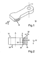
- eine perspektivische Ansicht einer Ausführungsform eines Verbindungselement der erfindungsgemäßen Verstelleinrichtung;
- Fig. 2
- eine Schnittansicht des Verbindungselement gemäß
Fig. 1 sowie eines Betätigungselements der erfindungsgemäßen Verstelleinrichtung, mittels welchem das Verbindungselement und damit eine Leitschaufel der Verstelleinrichtung einstellbar sind; - Fig. 3
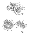
- eine perspektivische Teilschnittansicht einer Ausführungsform der erfindungsgemäßen Verstelleinrichtung; und
- Fig. 4
- zwei perspektivische Ansichten der Verstelleinrichtung gemäß
Fig. 3 . - Die
Fig. 1 zeigt ein Verbindungselement 10 einer Verstelleinrichtung 12 (Fig. 3 und 4 ) über welches eine jeweilige, an einem Haltering 42 (Fig. 3 und 4 ) gehaltene Leitschaufel 14 (Fig. 3 ) mittels eines Betätigungselements in Form eines Verstellrings 16 in ihrem Anstellwinkel einstellbar ist. Die Verstelleinrichtung 12 weist dabei eine Mehrzahl derartiger Leitschaufeln 14 sowie Verbindungselemente 10 auf, wobei in denFig. 3 und 4 jeweils nur eine Leitschaufel 14 und ein Verbindungselement 10 der Übersicht wegen mit Bezugszeichen versehen sind. - Zur Einstellung des Anstellwinkels ist das Verbindungselement 10 mit dem Verstellring 16 über jeweilige Kontaktbereich 18 und 20 in Wirkverbindung bringbar, was durch Drehung des Verstellrings 16 gemäß einem Richtungspfeil 22 erfolgt. Die Drehung des Verstellrings 16 erfolgt dabei über eine Verstellwelle 24, die mittels einer Lagerungseinrichtung 26 in einem nicht dargestellten Gehäuse der Verstelleinrichtung 10 gelagert ist. Die Verstellwelle 24 wiederum wird von einer Verstellplatte 28 betätigt, die wiederum von einem nicht dargestellten Aktuator betätigbar ist. Die Drehung der Verstellwelle 24 wird dabei über einen Verstellhebel 30 auf den Verstellring 16 übertragen, wobei der Verstellhebel 30 in eine entsprechende Nut des Verstellrings 16 eingreift. Ebenso greifen die Verbindungselemente 10 in korrespondierende Nuten des Verstellrings 16 ein.
- Insbesondere der
Fig. 4 deutlich zu entnehmen ist, dass bei einer Drehung des Verstellrings 16 entsprechende Flanken der Verbindungselemente 10 mit korrespondierenden Flanken des Verstellrings 16 in Kontakt und damit in Wirkverbindung geraten, wodurch also die Kontaktbereiche 18 und 20 aneinander anliegen. Eine Drehung des Verstellrings 16 führ dabei zu einer Drehung bzw. zu einem Verschwenken des Verbindungselements 10 um eine Drehachse 11. - Wie der
Fig. 2 zu entnehmen ist, sind die jeweiligen Verbindungselemente 10 und der Verstellring 16 über schräg zur axialen Richtung gemäß einem Richtungspfeil 32. der Verstelleinrichtung 12 verlaufende Wirkflächen 34 und 36 in Wirkverbindung bringbar, wodurch ein Schub des Verbindungselements 10 und damit der Leitschaufel 14 parallel zur axialen Richtung gemäß dem Richtungspfeil 32 in Richtung eines Turbinenradaustritts eines nicht dargestellten Turbinenrads gemäß einem Richtungspfeil 38 realisiert ist. - Dieser Schub erlaubt eine definierte Positionierung des Verbindungselements 10 und damit der Leitschaufel 14 in axialer Richtung und vermeidet somit eine unkontrollierte Bewegung dieser in diese Richtung, was einem sehr geringen Verschleiß der Verstelleinrichtung 12 zugute kommt. Ebenso vorteilhaft wirkt sich diese definierte, axiale Positionierung des Verbindungselements 10 und der Leitschaufel 14 auf Spaltverluste der Verstelleinrichtung aus, die also äußerst gering sind, was ein effizienten Betrieb einer Aufladeeinrichtung, beispielsweise eines Abgasturboladers, bei welcher die Verstelleinrichtung 12 einsetzbar ist, ermöglicht. Dies bedeutet also eine Wirkungsgradsteigerung der Aufladeeinrichtung, was sich auch positiv auf eine in Zusammenhang mit der Verstelleinrichtung 12 eingesetzte Verbrennungskraftmaschine auswirkt, wodurch deren Kraftstoffverbrauch und deren CO2-Emissionen gering gehalten werden können.
- Gemäß den
Fig. 3 und 4 umfasst die Verstelleinrichtung 12 zudem Abstandshaltebolzen 40, mittels welchen der Haltering 42 von einem eine Düse 46 bildenden Ringelement 44 beabstandet ist. Zudem sind ein Stützring 46, ein Anschlagsstift 48 sowie ein dem Verstellring 16 zugeordneter Stützring 50 vorgesehen. - Ein Richtungspfeil 52 kennzeichnet dabei in
Fig. 3 die Richtung, in welche die Verbindungselemente 10 und damit die Leitschaufeln 14 infolge der schrägen Ausbildung der Wirkflächen 34, 36 bewegbar bzw. drückbar sind. - Beispielhaft in der
Fig. 2 dargestellt ist, dass die Wirkfläche 34 mit der axialen Richtung gemäß dem Richtungspfeil 32 einen Winkel α einschließt, wodurch die schräge Wirkfläche 34 dargestellt ist, und wobei die ebenfalls schräge Wirkfläche 36 zumindest im Wesentlichen parallel zur Wirkfläche 34 verläuft, wodurch die definierte Positionierung und das Halten in dieser definierten Position der Betätigungselemente 10 und damit der Leitschaufeln 14 realisiert ist. Die Verstelleinrichtung 12 ist beispielsweise auch bei anderweitigen Anwendungsfällen, so zum Beispiel in Zusammenhang mit einem Verdichter der Aufladeeinrichtung, analog einsetzbar.
Claims (6)
- Verstelleinrichtung (12) für eine Aufladeeinrichtung, insbesondere einen Abgasturbolader, mit zumindest einem Halteelement (42), insbesondere einem Haltering (42), an welchem eine Mehrzahl von Leitschaufeln (14) gehalten ist, welche über ein jeweiliges Verbindungselement (10) mit einem Betätigungselement (16), insbesondere einem Verstellring (16), in Wirkverbindung bringbar und welche mittels des Betätigungselements (16) in ihrem jeweiligen Anstellwinkel einstellbar sind,
dadurch gekennzeichnet, dass
das jeweilige Verbindungselement (10) mit dem Betätigungselement (16) über zumindest eine schräg zur axialen Richtung der Verstelleinrichtung (12) verlaufende Wirkfläche (34, 36) in Wirkverbindung bringbar ist. - Verstelleinrichtung (12) nach Anspruch 1,
dadurch gekennzeichnet, dass
die schräge Wirkfläche (34, 36) an dem Verbindungselement (10) vorgesehen ist. - Verstelleinrichtung (12) nach einem der Ansprüche 1 oder 2,
dadurch gekennzeichnet, dass
die schräge Wirkfläche (34, 36) an dem Betätigungselement (16) vorgesehen ist. - Verstelleinrichtung (12) nach einem der vorhergehenden Ansprüche,
dadurch gekennzeichnet, dass
die Leitschaufeln (14) drehbar an dem Halteelement (42) gehalten sind. - Verstelleinrichtung (12) nach einem der vorhergehenden Ansprüche,
dadurch gekennzeichnet, dass
ein Laufrad vorgesehen ist, welches als Turbinenrad ausgebildet ist, wobei die jeweilige Leitschaufel (14) mittels der schrägen Wirkfläche (34, 36) in Richtung eines Turbinenradaustritts bewegbar ist. - Verstelleinrichtung (12) nach einem der vorhergehenden Ansprüche,
dadurch gekennzeichnet, dass
das jeweilige Verbindungselement (10) und/oder die jeweilige Leitschaufel (14) und/oder das Betätigungselement (16) durch ein Metallpulver-Spritzgieß-Verfahren ausgebildet ist bzw. sind.
Applications Claiming Priority (2)
| Application Number | Priority Date | Filing Date | Title |
|---|---|---|---|
| DE200910057664 DE102009057664A1 (de) | 2009-12-09 | 2009-12-09 | Verstelleinrichtung für eine Aufladeeinrichtung, insbesondere für einen Abgasturbolader |
| PCT/EP2010/006384 WO2011069574A1 (de) | 2009-12-09 | 2010-10-19 | Verstelleinrichtung für eine aufladeeinrichtung, insbesondere für einen abgasturbolader |
Publications (2)
| Publication Number | Publication Date |
|---|---|
| EP2510207A1 EP2510207A1 (de) | 2012-10-17 |
| EP2510207B1 true EP2510207B1 (de) | 2015-12-23 |
Family
ID=43270538
Family Applications (1)
| Application Number | Title | Priority Date | Filing Date |
|---|---|---|---|
| EP10772979.0A Active EP2510207B1 (de) | 2009-12-09 | 2010-10-19 | Verstelleinrichtung für eine Aufladeeinrichtung, insbesondere für einen Abgasturbolader |
Country Status (6)
| Country | Link |
|---|---|
| US (1) | US9022729B2 (de) |
| EP (1) | EP2510207B1 (de) |
| JP (1) | JP5632484B2 (de) |
| CN (1) | CN102656352B (de) |
| DE (1) | DE102009057664A1 (de) |
| WO (1) | WO2011069574A1 (de) |
Families Citing this family (5)
| Publication number | Priority date | Publication date | Assignee | Title |
|---|---|---|---|---|
| WO2013191941A1 (en) * | 2012-06-19 | 2013-12-27 | Borgwarner Inc. | Exhaust-gas turbocharger |
| WO2015089350A1 (en) * | 2013-12-13 | 2015-06-18 | Borgwarner Inc. | Adjustment ring damper |
| DE102015004649A1 (de) * | 2015-04-15 | 2016-10-20 | Man Diesel & Turbo Se | Leitschaufelverstellvorrichtung und Strömungsmaschine |
| DE102015212808A1 (de) | 2015-07-08 | 2017-01-12 | Continental Automotive Gmbh | Abgasturbolader mit verstellbarer Turbinengeometrie |
| US10619508B2 (en) * | 2017-11-03 | 2020-04-14 | Borgwarner, Inc. | Variable turbine geometry vane lever |
Citations (1)
| Publication number | Priority date | Publication date | Assignee | Title |
|---|---|---|---|---|
| WO2007093407A1 (de) * | 2006-02-16 | 2007-08-23 | Borgwarner Inc. | Turbolader mit verstellbaren leitschaufeln, schaufelhebel und verstellring dafür |
Family Cites Families (13)
| Publication number | Priority date | Publication date | Assignee | Title |
|---|---|---|---|---|
| US4804316A (en) * | 1985-12-11 | 1989-02-14 | Allied-Signal Inc. | Suspension for the pivoting vane actuation mechanism of a variable nozzle turbocharger |
| EP0571205B1 (de) * | 1992-05-21 | 1997-03-05 | Alliedsignal Limited | Regelbarer Turbolader |
| JPH06185787A (ja) * | 1992-12-18 | 1994-07-08 | Fujitsu General Ltd | 空気調和機の制御方法 |
| JP3771765B2 (ja) * | 2000-01-24 | 2006-04-26 | 三菱重工業株式会社 | 可変ターボチャージャ |
| DE60024879T2 (de) * | 2000-03-13 | 2006-07-20 | Alliedsignal Inc. | Turbolader mit verstellbaren leitschaufeln |
| JP3473562B2 (ja) * | 2000-07-31 | 2003-12-08 | トヨタ自動車株式会社 | 可変ノズルベーン付きターボチャージャ |
| JP3944819B2 (ja) * | 2001-08-03 | 2007-07-18 | 株式会社アキタファインブランキング | Vgsタイプターボチャージャにおける排気ガイドアッセンブリに適用される可変翼の翼部の製造方法 |
| WO2007034787A1 (ja) | 2005-09-26 | 2007-03-29 | Nec Corporation | 携帯電話端末、データ処理開始方法、データ伝送方法 |
| EP2018480B1 (de) * | 2006-05-19 | 2016-06-15 | BorgWarner, Inc. | Turbolader |
| JP2009243431A (ja) * | 2008-03-31 | 2009-10-22 | Ihi Corp | 可変ノズルユニット及び可変容量型ターボチャージャ |
| US20110138805A1 (en) * | 2009-12-15 | 2011-06-16 | Honeywell International Inc. | Conjugate curve profiles for vane arms, main-arms, and unison rings |
| DE102011005556A1 (de) * | 2011-03-15 | 2012-09-20 | Bosch Mahle Turbo Systems Gmbh & Co. Kg | Verstellring |
| US8985943B2 (en) * | 2011-09-30 | 2015-03-24 | Honeywell International Inc. | Turbocharger variable-nozzle assembly with vane sealing arrangement |
-
2009
- 2009-12-09 DE DE200910057664 patent/DE102009057664A1/de not_active Withdrawn
-
2010
- 2010-10-19 WO PCT/EP2010/006384 patent/WO2011069574A1/de not_active Ceased
- 2010-10-19 JP JP2012542374A patent/JP5632484B2/ja not_active Expired - Fee Related
- 2010-10-19 CN CN201080055236.5A patent/CN102656352B/zh not_active Expired - Fee Related
- 2010-10-19 EP EP10772979.0A patent/EP2510207B1/de active Active
-
2012
- 2012-06-05 US US13/489,184 patent/US9022729B2/en active Active
Patent Citations (1)
| Publication number | Priority date | Publication date | Assignee | Title |
|---|---|---|---|---|
| WO2007093407A1 (de) * | 2006-02-16 | 2007-08-23 | Borgwarner Inc. | Turbolader mit verstellbaren leitschaufeln, schaufelhebel und verstellring dafür |
Also Published As
| Publication number | Publication date |
|---|---|
| US9022729B2 (en) | 2015-05-05 |
| WO2011069574A1 (de) | 2011-06-16 |
| JP2013513746A (ja) | 2013-04-22 |
| DE102009057664A1 (de) | 2011-06-16 |
| EP2510207A1 (de) | 2012-10-17 |
| JP5632484B2 (ja) | 2014-11-26 |
| US20120243973A1 (en) | 2012-09-27 |
| CN102656352B (zh) | 2015-11-25 |
| CN102656352A (zh) | 2012-09-05 |
Similar Documents
| Publication | Publication Date | Title |
|---|---|---|
| EP2002127B1 (de) | Vordrall-leitvorrichtung | |
| EP2018480B1 (de) | Turbolader | |
| EP2209969B1 (de) | Ladeeinrichtung | |
| DE102010008411B4 (de) | Turbine für einen Abgasturbolader | |
| EP1984601B1 (de) | Turbolader mit verstellbaren leitschaufeln, schaufelhebel und verstellring dafür | |
| EP1977084B1 (de) | Verstellbare leitvorrichtung | |
| DE102010038185B4 (de) | Düseneinrichtung eines Turboladers variabler Geometrie | |
| EP2785982A1 (de) | Fluidenergiemaschine, insbesondere für einen abgasturbolader, mit schräg angeordnetem, drehbarem leitelement | |
| EP1520959B1 (de) | Turbokompressor mit verstellbaren Leitschaufeln | |
| WO2011069574A1 (de) | Verstelleinrichtung für eine aufladeeinrichtung, insbesondere für einen abgasturbolader | |
| EP1977085A1 (de) | Verstellbare leitvorrichtung | |
| EP1998026A2 (de) | Ladeeinrichtung | |
| EP2707575B1 (de) | Variable turbinen-/verdichtergeometrie | |
| DE202021004007U1 (de) | Radialgasturbine | |
| DE102008000508A1 (de) | Abgasturbolader mit verstellbarer Turbinengeometrie | |
| DE102017118795B4 (de) | Verstellbarer Leitapparat für eine Turbine, Turbine für einen Abgasturbolader und Abgasturbolader | |
| DE102008049005A1 (de) | Ladeeinrichtung | |
| EP2071134A2 (de) | Variable Turbinengeometrie | |
| DE102015216306A1 (de) | Leitschaufel für eine variable Turbinengeometrie, Verfahren zur Herstellung einer Leitschaufel und Turbolader mit einer Leitschaufel | |
| DE102007052735B4 (de) | Ladeeinrichtung | |
| EP1635038B1 (de) | Abgasturbolader | |
| EP4168655A1 (de) | Modularer düsenring für eine turbinenstufe einer strömungsmaschine | |
| DE102018126589A1 (de) | Verstellbares Leitschaufelsystem für einen Abgasturbolader | |
| EP2067962A2 (de) | Turbine eines Abgasturboladers einer Brennkraftmaschine | |
| DE102007052736B4 (de) | Ladeeinrichtung mit einer variablen Turbinen- und/oder Verdichtergeometrie |
Legal Events
| Date | Code | Title | Description |
|---|---|---|---|
| PUAI | Public reference made under article 153(3) epc to a published international application that has entered the european phase |
Free format text: ORIGINAL CODE: 0009012 |
|
| 17P | Request for examination filed |
Effective date: 20120416 |
|
| AK | Designated contracting states |
Kind code of ref document: A1 Designated state(s): AL AT BE BG CH CY CZ DE DK EE ES FI FR GB GR HR HU IE IS IT LI LT LU LV MC MK MT NL NO PL PT RO RS SE SI SK SM TR |
|
| DAX | Request for extension of the european patent (deleted) | ||
| GRAP | Despatch of communication of intention to grant a patent |
Free format text: ORIGINAL CODE: EPIDOSNIGR1 |
|
| INTG | Intention to grant announced |
Effective date: 20150804 |
|
| GRAS | Grant fee paid |
Free format text: ORIGINAL CODE: EPIDOSNIGR3 |
|
| GRAA | (expected) grant |
Free format text: ORIGINAL CODE: 0009210 |
|
| AK | Designated contracting states |
Kind code of ref document: B1 Designated state(s): AL AT BE BG CH CY CZ DE DK EE ES FI FR GB GR HR HU IE IS IT LI LT LU LV MC MK MT NL NO PL PT RO RS SE SI SK SM TR |
|
| REG | Reference to a national code |
Ref country code: GB Ref legal event code: FG4D Free format text: NOT ENGLISH |
|
| REG | Reference to a national code |
Ref country code: CH Ref legal event code: EP |
|
| REG | Reference to a national code |
Ref country code: IE Ref legal event code: FG4D Free format text: LANGUAGE OF EP DOCUMENT: GERMAN |
|
| REG | Reference to a national code |
Ref country code: AT Ref legal event code: REF Ref document number: 766680 Country of ref document: AT Kind code of ref document: T Effective date: 20160115 |
|
| REG | Reference to a national code |
Ref country code: DE Ref legal event code: R096 Ref document number: 502010010837 Country of ref document: DE |
|
| REG | Reference to a national code |
Ref country code: LT Ref legal event code: MG4D |
|
| REG | Reference to a national code |
Ref country code: NL Ref legal event code: MP Effective date: 20151223 |
|
| PG25 | Lapsed in a contracting state [announced via postgrant information from national office to epo] |
Ref country code: HR Free format text: LAPSE BECAUSE OF FAILURE TO SUBMIT A TRANSLATION OF THE DESCRIPTION OR TO PAY THE FEE WITHIN THE PRESCRIBED TIME-LIMIT Effective date: 20151223 Ref country code: LT Free format text: LAPSE BECAUSE OF FAILURE TO SUBMIT A TRANSLATION OF THE DESCRIPTION OR TO PAY THE FEE WITHIN THE PRESCRIBED TIME-LIMIT Effective date: 20151223 Ref country code: NO Free format text: LAPSE BECAUSE OF FAILURE TO SUBMIT A TRANSLATION OF THE DESCRIPTION OR TO PAY THE FEE WITHIN THE PRESCRIBED TIME-LIMIT Effective date: 20160323 |
|
| PG25 | Lapsed in a contracting state [announced via postgrant information from national office to epo] |
Ref country code: FI Free format text: LAPSE BECAUSE OF FAILURE TO SUBMIT A TRANSLATION OF THE DESCRIPTION OR TO PAY THE FEE WITHIN THE PRESCRIBED TIME-LIMIT Effective date: 20151223 Ref country code: RS Free format text: LAPSE BECAUSE OF FAILURE TO SUBMIT A TRANSLATION OF THE DESCRIPTION OR TO PAY THE FEE WITHIN THE PRESCRIBED TIME-LIMIT Effective date: 20151223 Ref country code: NL Free format text: LAPSE BECAUSE OF FAILURE TO SUBMIT A TRANSLATION OF THE DESCRIPTION OR TO PAY THE FEE WITHIN THE PRESCRIBED TIME-LIMIT Effective date: 20151223 Ref country code: LV Free format text: LAPSE BECAUSE OF FAILURE TO SUBMIT A TRANSLATION OF THE DESCRIPTION OR TO PAY THE FEE WITHIN THE PRESCRIBED TIME-LIMIT Effective date: 20151223 Ref country code: GR Free format text: LAPSE BECAUSE OF FAILURE TO SUBMIT A TRANSLATION OF THE DESCRIPTION OR TO PAY THE FEE WITHIN THE PRESCRIBED TIME-LIMIT Effective date: 20160324 Ref country code: SE Free format text: LAPSE BECAUSE OF FAILURE TO SUBMIT A TRANSLATION OF THE DESCRIPTION OR TO PAY THE FEE WITHIN THE PRESCRIBED TIME-LIMIT Effective date: 20151223 |
|
| PG25 | Lapsed in a contracting state [announced via postgrant information from national office to epo] |
Ref country code: IT Free format text: LAPSE BECAUSE OF FAILURE TO SUBMIT A TRANSLATION OF THE DESCRIPTION OR TO PAY THE FEE WITHIN THE PRESCRIBED TIME-LIMIT Effective date: 20151223 Ref country code: ES Free format text: LAPSE BECAUSE OF FAILURE TO SUBMIT A TRANSLATION OF THE DESCRIPTION OR TO PAY THE FEE WITHIN THE PRESCRIBED TIME-LIMIT Effective date: 20151223 Ref country code: CZ Free format text: LAPSE BECAUSE OF FAILURE TO SUBMIT A TRANSLATION OF THE DESCRIPTION OR TO PAY THE FEE WITHIN THE PRESCRIBED TIME-LIMIT Effective date: 20151223 |
|
| PG25 | Lapsed in a contracting state [announced via postgrant information from national office to epo] |
Ref country code: PL Free format text: LAPSE BECAUSE OF FAILURE TO SUBMIT A TRANSLATION OF THE DESCRIPTION OR TO PAY THE FEE WITHIN THE PRESCRIBED TIME-LIMIT Effective date: 20151223 Ref country code: SM Free format text: LAPSE BECAUSE OF FAILURE TO SUBMIT A TRANSLATION OF THE DESCRIPTION OR TO PAY THE FEE WITHIN THE PRESCRIBED TIME-LIMIT Effective date: 20151223 Ref country code: RO Free format text: LAPSE BECAUSE OF FAILURE TO SUBMIT A TRANSLATION OF THE DESCRIPTION OR TO PAY THE FEE WITHIN THE PRESCRIBED TIME-LIMIT Effective date: 20151223 Ref country code: SK Free format text: LAPSE BECAUSE OF FAILURE TO SUBMIT A TRANSLATION OF THE DESCRIPTION OR TO PAY THE FEE WITHIN THE PRESCRIBED TIME-LIMIT Effective date: 20151223 Ref country code: EE Free format text: LAPSE BECAUSE OF FAILURE TO SUBMIT A TRANSLATION OF THE DESCRIPTION OR TO PAY THE FEE WITHIN THE PRESCRIBED TIME-LIMIT Effective date: 20151223 Ref country code: PT Free format text: LAPSE BECAUSE OF FAILURE TO SUBMIT A TRANSLATION OF THE DESCRIPTION OR TO PAY THE FEE WITHIN THE PRESCRIBED TIME-LIMIT Effective date: 20160426 Ref country code: IS Free format text: LAPSE BECAUSE OF FAILURE TO SUBMIT A TRANSLATION OF THE DESCRIPTION OR TO PAY THE FEE WITHIN THE PRESCRIBED TIME-LIMIT Effective date: 20160423 |
|
| REG | Reference to a national code |
Ref country code: DE Ref legal event code: R097 Ref document number: 502010010837 Country of ref document: DE |
|
| PLBE | No opposition filed within time limit |
Free format text: ORIGINAL CODE: 0009261 |
|
| STAA | Information on the status of an ep patent application or granted ep patent |
Free format text: STATUS: NO OPPOSITION FILED WITHIN TIME LIMIT |
|
| PG25 | Lapsed in a contracting state [announced via postgrant information from national office to epo] |
Ref country code: DK Free format text: LAPSE BECAUSE OF FAILURE TO SUBMIT A TRANSLATION OF THE DESCRIPTION OR TO PAY THE FEE WITHIN THE PRESCRIBED TIME-LIMIT Effective date: 20151223 |
|
| 26N | No opposition filed |
Effective date: 20160926 |
|
| PG25 | Lapsed in a contracting state [announced via postgrant information from national office to epo] |
Ref country code: SI Free format text: LAPSE BECAUSE OF FAILURE TO SUBMIT A TRANSLATION OF THE DESCRIPTION OR TO PAY THE FEE WITHIN THE PRESCRIBED TIME-LIMIT Effective date: 20151223 Ref country code: BE Free format text: LAPSE BECAUSE OF NON-PAYMENT OF DUE FEES Effective date: 20161031 |
|
| REG | Reference to a national code |
Ref country code: CH Ref legal event code: PL |
|
| GBPC | Gb: european patent ceased through non-payment of renewal fee |
Effective date: 20161019 |
|
| REG | Reference to a national code |
Ref country code: IE Ref legal event code: MM4A |
|
| REG | Reference to a national code |
Ref country code: FR Ref legal event code: ST Effective date: 20170630 |
|
| PG25 | Lapsed in a contracting state [announced via postgrant information from national office to epo] |
Ref country code: CH Free format text: LAPSE BECAUSE OF NON-PAYMENT OF DUE FEES Effective date: 20161031 Ref country code: GB Free format text: LAPSE BECAUSE OF NON-PAYMENT OF DUE FEES Effective date: 20161019 Ref country code: LI Free format text: LAPSE BECAUSE OF NON-PAYMENT OF DUE FEES Effective date: 20161031 Ref country code: FR Free format text: LAPSE BECAUSE OF NON-PAYMENT OF DUE FEES Effective date: 20161102 |
|
| PG25 | Lapsed in a contracting state [announced via postgrant information from national office to epo] |
Ref country code: LU Free format text: LAPSE BECAUSE OF NON-PAYMENT OF DUE FEES Effective date: 20161019 |
|
| PG25 | Lapsed in a contracting state [announced via postgrant information from national office to epo] |
Ref country code: IE Free format text: LAPSE BECAUSE OF NON-PAYMENT OF DUE FEES Effective date: 20161019 |
|
| REG | Reference to a national code |
Ref country code: BE Ref legal event code: MM Effective date: 20161031 |
|
| REG | Reference to a national code |
Ref country code: AT Ref legal event code: MM01 Ref document number: 766680 Country of ref document: AT Kind code of ref document: T Effective date: 20161019 |
|
| PG25 | Lapsed in a contracting state [announced via postgrant information from national office to epo] |
Ref country code: AT Free format text: LAPSE BECAUSE OF NON-PAYMENT OF DUE FEES Effective date: 20161019 |
|
| PG25 | Lapsed in a contracting state [announced via postgrant information from national office to epo] |
Ref country code: HU Free format text: LAPSE BECAUSE OF FAILURE TO SUBMIT A TRANSLATION OF THE DESCRIPTION OR TO PAY THE FEE WITHIN THE PRESCRIBED TIME-LIMIT; INVALID AB INITIO Effective date: 20101019 Ref country code: CY Free format text: LAPSE BECAUSE OF FAILURE TO SUBMIT A TRANSLATION OF THE DESCRIPTION OR TO PAY THE FEE WITHIN THE PRESCRIBED TIME-LIMIT Effective date: 20151223 |
|
| PG25 | Lapsed in a contracting state [announced via postgrant information from national office to epo] |
Ref country code: MK Free format text: LAPSE BECAUSE OF FAILURE TO SUBMIT A TRANSLATION OF THE DESCRIPTION OR TO PAY THE FEE WITHIN THE PRESCRIBED TIME-LIMIT Effective date: 20151223 Ref country code: MC Free format text: LAPSE BECAUSE OF FAILURE TO SUBMIT A TRANSLATION OF THE DESCRIPTION OR TO PAY THE FEE WITHIN THE PRESCRIBED TIME-LIMIT Effective date: 20151223 Ref country code: TR Free format text: LAPSE BECAUSE OF FAILURE TO SUBMIT A TRANSLATION OF THE DESCRIPTION OR TO PAY THE FEE WITHIN THE PRESCRIBED TIME-LIMIT Effective date: 20151223 Ref country code: MT Free format text: LAPSE BECAUSE OF FAILURE TO SUBMIT A TRANSLATION OF THE DESCRIPTION OR TO PAY THE FEE WITHIN THE PRESCRIBED TIME-LIMIT Effective date: 20151223 |
|
| PG25 | Lapsed in a contracting state [announced via postgrant information from national office to epo] |
Ref country code: BG Free format text: LAPSE BECAUSE OF FAILURE TO SUBMIT A TRANSLATION OF THE DESCRIPTION OR TO PAY THE FEE WITHIN THE PRESCRIBED TIME-LIMIT Effective date: 20151223 |
|
| PG25 | Lapsed in a contracting state [announced via postgrant information from national office to epo] |
Ref country code: AL Free format text: LAPSE BECAUSE OF FAILURE TO SUBMIT A TRANSLATION OF THE DESCRIPTION OR TO PAY THE FEE WITHIN THE PRESCRIBED TIME-LIMIT Effective date: 20151223 |
|
| REG | Reference to a national code |
Ref country code: DE Ref legal event code: R082 Ref document number: 502010010837 Country of ref document: DE Representative=s name: HEEB-KELLER, ANNETTE, DR., DE Ref country code: DE Ref legal event code: R081 Ref document number: 502010010837 Country of ref document: DE Owner name: IHI CHARGING SYSTEMS INTERNATIONAL GMBH, DE Free format text: FORMER OWNER: IHI CHARGING SYSTEMS INTERNATIONAL GMBH, 69126 HEIDELBERG, DE |
|
| P01 | Opt-out of the competence of the unified patent court (upc) registered |
Effective date: 20230530 |
|
| REG | Reference to a national code |
Ref country code: DE Ref legal event code: R082 Ref document number: 502010010837 Country of ref document: DE Representative=s name: TBK, DE Ref country code: DE Ref legal event code: R081 Ref document number: 502010010837 Country of ref document: DE Owner name: IHI CORPORATION, JP Free format text: FORMER OWNER: IHI CHARGING SYSTEMS INTERNATIONAL GMBH, 99334 AMT WACHSENBURG, DE |
|
| PGFP | Annual fee paid to national office [announced via postgrant information from national office to epo] |
Ref country code: DE Payment date: 20251029 Year of fee payment: 16 |