EP2510188B1 - Device and method for the recovery, in particular in situ recovery, of a carbonaceous substance from subterranean formations - Google Patents
Device and method for the recovery, in particular in situ recovery, of a carbonaceous substance from subterranean formations Download PDFInfo
- Publication number
- EP2510188B1 EP2510188B1 EP10788299.5A EP10788299A EP2510188B1 EP 2510188 B1 EP2510188 B1 EP 2510188B1 EP 10788299 A EP10788299 A EP 10788299A EP 2510188 B1 EP2510188 B1 EP 2510188B1
- Authority
- EP
- European Patent Office
- Prior art keywords
- fluid
- reservoir
- conducting means
- conductor
- fluid conducting
- Prior art date
- Legal status (The legal status is an assumption and is not a legal conclusion. Google has not performed a legal analysis and makes no representation as to the accuracy of the status listed.)
- Not-in-force
Links
Images


Classifications
-
- E—FIXED CONSTRUCTIONS
- E21—EARTH DRILLING; MINING
- E21B—EARTH DRILLING, e.g. DEEP DRILLING; OBTAINING OIL, GAS, WATER, SOLUBLE OR MELTABLE MATERIALS OR A SLURRY OF MINERALS FROM WELLS
- E21B43/00—Methods or apparatus for obtaining oil, gas, water, soluble or meltable materials or a slurry of minerals from wells
- E21B43/16—Enhanced recovery methods for obtaining hydrocarbons
- E21B43/24—Enhanced recovery methods for obtaining hydrocarbons using heat, e.g. steam injection
- E21B43/2401—Enhanced recovery methods for obtaining hydrocarbons using heat, e.g. steam injection by means of electricity
-
- E—FIXED CONSTRUCTIONS
- E21—EARTH DRILLING; MINING
- E21B—EARTH DRILLING, e.g. DEEP DRILLING; OBTAINING OIL, GAS, WATER, SOLUBLE OR MELTABLE MATERIALS OR A SLURRY OF MINERALS FROM WELLS
- E21B17/00—Drilling rods or pipes; Flexible drill strings; Kellies; Drill collars; Sucker rods; Cables; Casings; Tubings
- E21B17/18—Pipes provided with plural fluid passages
-
- E—FIXED CONSTRUCTIONS
- E21—EARTH DRILLING; MINING
- E21B—EARTH DRILLING, e.g. DEEP DRILLING; OBTAINING OIL, GAS, WATER, SOLUBLE OR MELTABLE MATERIALS OR A SLURRY OF MINERALS FROM WELLS
- E21B34/00—Valve arrangements for boreholes or wells
- E21B34/06—Valve arrangements for boreholes or wells in wells
-
- E—FIXED CONSTRUCTIONS
- E21—EARTH DRILLING; MINING
- E21B—EARTH DRILLING, e.g. DEEP DRILLING; OBTAINING OIL, GAS, WATER, SOLUBLE OR MELTABLE MATERIALS OR A SLURRY OF MINERALS FROM WELLS
- E21B43/00—Methods or apparatus for obtaining oil, gas, water, soluble or meltable materials or a slurry of minerals from wells
- E21B43/30—Specific pattern of wells, e.g. optimizing the spacing of wells
- E21B43/305—Specific pattern of wells, e.g. optimizing the spacing of wells comprising at least one inclined or horizontal well
Definitions
- the invention relates to an installation for the in situ recovery of a carbonaceous substance from an underground deposit with reduction of its viscosity.
- a device is used in particular for the production of bitumen or heavy oil from a reservoir under an overburden, as is the case with oil shale and / or oil sand deposits, for example in Canada.
- SAGD S team A ssisted G ravity D rainage
- water vapor is injected under high pressure through a tube running horizontally within the seam.
- the heated, molten bitumen or heavy oil removed from the sand or rock seeps to a second pipe located about 5 m lower, through which the liquefied bitumen or heavy oil is conveyed, the distance between injector and production pipe being dependent on reservoir geometry.
- the steam has to fulfill several tasks at the same time, namely the introduction of heating energy for liquefaction, the detachment of the sand and the pressure build-up in the reservoir, on the one hand to make the reservoir geomechanically permeable for bitumen transport (permeability) and on the other hand, the promotion of bitumen without additional pumps to enable.
- the SAGD process starts by introducing steam through both pipes, for example for three months, in order first to liquefy the bitumen in the space between the pipes as quickly as possible. Thereafter, the steam is introduced only through the upper tube and the promotion through the lower tube can begin.
- German patent application DE 10 2007 008 292 A1 It is already stated that the SAGD method commonly used for this purpose can be completed with an inductive heating device. Furthermore, in the German patent application DE 10 2007 036 832 A1 a device described in the parallel inductor or electrode assemblies are present, which are connected above ground to an oscillator or inverter.
- German patent applications DE 10 2007 008 292 A1 and DE 10 2007 036 832 A1 So it is proposed to superimpose the steam input with an inductive heating of the deposit.
- resistive heating between two electrodes may additionally be carried out.
- a variation of the heating power along the inductors can, as described in the earlier applications, be carried out specifically by sectionwise injection of electrolytes, whereby the impedance is changed. This requires corresponding electrolyte injection devices whose installation can be complicated or costly.
- a liquid solvent can be passed through a coaxial arrangement of an oil production tube and a surrounding liquid supply into the reservoir, wherein in a section in the reservoir coils may be provided to effect evaporation of the solvent, so that the now hot gaseous solvent can penetrate through a slotted jacket into a cavity surrounding the shell in the reservoir.
- the coils act directly on the liquid solvent still within the liquid supply, so that it already merges in the liquid supply in the gaseous state.
- the gaseous solvent may then disperse within the cavity and come into contact with the cold and viscous hydrocarbons in the reservoir.
- a device and method for conveying a hydrocarbon-containing substance, in particular bitumen or heavy oil are provided from a reservoir, wherein the reservoir can be acted upon by heat energy for reducing the viscosity of the substance, for which purpose at least one conductor loop for inductive energization as electrical and / or electromagnetic Heating is provided.
- a fluid guide for transporting and introducing a solvent fluid - hereinafter also referred to as "fluid" for short - is provided in the reservoir for the purpose of further reducing the viscosity of the substance and / or displacing it from the reservoir.
- the fluid guide is perforated, so that when the solvent fluid is supplied, the solvent fluid enters the reservoir via a perforation from the fluid guide. Furthermore, the perforation has holes which are designed in shape and / or size and / or distribution such that upon supply of the solvent fluid under a predetermined pressure, the solvent fluid distributed over a length of the fluid guide through the perforation in an environment of the fluid guide is discharged into the reservoir.
- the invention is therefore an "in situ” promotion, ie the promotion of the hydrocarbonaceous substance directly from the reservoir in which this substance enriched without mining the reservoir in the opencast mine.
- a reservoir is preferably understood an oil sands deposit that can be found underground.
- the solvent fluid may be formed as a gas, as a liquid or as a multi-component or multi-phase mixture.
- the conductor loop is essentially a twisted cable, usually encased in a tubular sheath.
- a section of the conductor loop along the extension of the cable is referred to below as a conductor.
- a conductor in particular a serial resonant circuit or a part thereof is understood, which is brought in a cable-like structure with external insulation.
- this can be surrounded by a fluid guide, by means of which the solvent fluid is injected into the reservoir.
- the fluid guide for the solvent fluid may be implemented separately from the conductor loop.
- the fluid guide is an extended hollow body, such as a tube or hose, through which the solvent fluid is transported.
- solvents both gases - such as ethane, propane, butane, CO 2 , SO 2 , etc. - as well as liquids - eg polymers or water mixtures with polymers (polyacrylamides, xanthan) - or water mixtures with admixture of wetting agents (eg. As surfactants) in question, which each solve in the bitumen of the deposit and reduce its viscosity.
- the solvents can be combined or mixed - for example, propane can be used as a solvent mixed with other gases (eg methane) - to ensure the volume flow and pressure required for the displacement of the oil.
- the conductor loop - also referred to as an inductor - and fluid guide - hereinafter also referred to as an injector - separated be educated.
- One or more fluid guides terminate in the reservoir and are configured such that the solvent fluid - the solvent - can enter the reservoir.
- the installation of the injector is possible both in vertical and horizontal drilling.
- the injector may have different positions with respect to the inductor and a production tube, for example above the inductor or between pairs of inductor and production tube.
- the inductor and the injector can also be combined coaxially.
- the inductor can be placed in a solvent-carrying pipe - the fluid guide - positioned centrally or eccentrically.
- an inductor may consist of several partial conductors, wherein the partial conductors of the inductor surround the fluid guide, which is used for the supply of the solvent.
- the fluid guide may be formed as a tube and / or tube, wherein a portion of the conductor loop - hereinafter referred to as conductor - is disposed within the tube or the tube, in particular so that when supplied with the solvent fluid, the conductor flows around the fluid becomes.
- conductor - a portion of the conductor loop - hereinafter referred to as conductor - is disposed within the tube or the tube, in particular so that when supplied with the solvent fluid, the conductor flows around the fluid becomes.
- the tube and / or the tube can be arranged approximately coaxially-centered or eccentrically-to the conductor.
- at least one web can be provided within the tube or the tube.
- a web can also have an axial extent, which even extends in a particular embodiment over the entire length of the hose / tube.
- the fluid guide may be in the center and may be surrounded by a tubular, coaxial conductor.
- the advantage here is that the fluid is conducted in the electromagnetic field-free interior, so that even an electrically conductive fluid undergoes no heating by eddy currents.
- the conductor may also be freely movable within the tube or tube, i. the conductor is uncentered in the tube or in the tube and means for fixing is omitted.
- the fluid guide may be formed as a plurality of hoses and / or tubes.
- a plurality of capillaries and / or a porous material may be provided to transport the fluid in the fluid guide.
- These variants are preferably arranged such that the conductor is surrounded by the plurality of tubes and / or tubes and / or capillaries and / or the porous material, wherein preferably the plurality of tubes and / or tubes and / or capillaries and / or the porous material and the conductor are arranged within a common tubular outer shell.
- These mentioned means for guiding the fluid are in particular all parallel to each other or twisted.
- a conductor is composed of a plurality of partial conductors and these partial conductors can be arranged around the fluid guide.
- the fluid guide is perforated, so that when a fluid is supplied, the fluid from the fluid guide penetrates through the perforation into the reservoir or is initiated.
- perforation is meant, for example, holes or slits located in a fluid guide so that the fluid can exit the interior of the fluid guide to the outside in the vicinity of the holes or slots.
- the fluid guide at least partially consists of porous material or capillaries, so that the fluid can be discharged by these means to the environment.
- the perforation may be formed and / or means may be provided to substantially prevent intrusion of solids and / or sands from the reservoir.
- the perforation should be designed such that over the entire length of the fluid guide - apart from the supply from the surface to the target region in the reservoir - in each section, the same amount of fluid is discharged.
- the perforation is preferably carried out to be electrically insulating so as not to establish a direct electrical connection between the conductor and the reservoir via the fluid.
- the introduction of the fluid into the reservoir can thereby reduce the viscosity in the reservoir and / or increase the pressure in the reservoir.
- a pressure increasing means for increasing the pressure of the fluid may be provided in the fluid guide, in particular a pump, so that by means of the pressure increasing means, a movement of the liquid is achieved in the fluid guide and so introduced by means of the pressure increasing means, the fluid with increased pressure in the fluid guide can be.
- so much pressure is to be generated by the pump that a predetermined amount of fluid penetrates into the reservoir via the perforation.
- increase pressure is thus meant that an ambient pressure in the reservoir should be overcome.
- the hydrostatic pressure in the reservoir in the vicinity of the perforation should be exceeded so that the fluid can escape, which can be achieved for example with a pressure of 5000 hPa (5 bar) to 50,000 hPa (50 bar).
- a compressor can be used which can feed one or more injection bores and fluid ducts laid therein.
- the increase in the pressure in the reservoir is particularly advantageous in that it better displaces the hydrocarbonaceous substance in the reservoir and / or avoids a negative pressure in the reservoir due to the delivery of the substance.
- the pressure applied via the feed to the fluid in the fluid guide is adapted to a predetermined perforation such that leakage of the fluid through the perforation over a longer period of use is ensured.
- a valve of a production tubing for carrying the liquefied hydrocarbonaceous substance out of the reservoir may be closed and opened at a later time, depending on the attainment of a predetermined period of time or upon reaching a predetermined pressure within the reservoir.
- the pressure can be increased because no material leaves the reservoir and additionally a fluid is introduced.
- two separate fluid guides may be provided for the conductor loop, each for one half of the conductor loop, wherein the two fluid guides terminate in the reservoir, so that the fluid can be fully introduced into the reservoir.
- composition may have the fluid that is fed into the reservoir. It is particularly advantageous if a portion of the fluid is at least partially or completely extracted from the funded water-oil / bitumen mixture, for example, a natural gas or water.
- the desired substance to be conveyed should be separated from the extracted water-oil / bitumen mixture and the gaseous or aqueous residue be post-processed or processed. This residue can then be reintroduced into the reservoir (i.e., according to a closed loop).
- FIG. 1 shows, shown schematically, a device for in-situ recovery of a hydrocarbonaceous substance from an underground reservoir 6 as a reservoir while reducing their viscosity, which in addition to an inductive heating of the reservoir by means of inductors 10 is also provided a supply of solvents.
- a device may be, for example, an apparatus for recovering bitumen from an oil sands deposit.
- the deposit 6 may be, in particular, an oil sands deposit or an oil shale deposit from which bitumen or other heavy oils may be recovered.
- FIG. 1 there is a conductor loop which is operated by an electrical supply 1. Portions of the conductor loop which act as an electrode are highlighted as inductor 10. These are the horizontal and parallel in the deposit 6 extending sections.
- the apparatus for in situ recovery of a hydrocarbonaceous substance has said inductor 10 extending into wells within the reservoir 6.
- the inductor 10 or portions thereof is considered a conductor and forms a conductor loop.
- the closed conductor loop consists of the two horizontally extending in the reservoir 6 back and forth conductors of the inductor 10, and of conductor pieces 11 which act little or no heating and run above ground or from the earth's surface 5 into the deposit 6 lead to the Power connection for the inductor 10 to ensure.
- both loop ends of the conductor loop are arranged above ground.
- the loop is simply closed - see leader 11 in the figure.
- an electrical supply 1 including all the necessary electrical equipment such as inverter and generator, through which the necessary power and the necessary voltage is applied to the conductor loop, so that the inductors 10 as a conductor for an electric / electromagnetic heater for heat generation in the Site 6 serve.
- the inductors 10 are effective against at least parts of the deposit 6 as an inductive electric heater. Due to the conductivity of at least parts of the deposit 6, this can be heated by the largely concentric around the two as possible parallel sections of the inductor 10.
- the inductor 10 may be rod-shaped metallic conductors or twisted metallic cables made of a metal that is in particular highly conductive, which are formed as a resonant circuit.
- a device is now provided by means of which a solvent fluid is introduced into the reservoir.
- This fluid 14 is introduced by means of the pump 2 - or in the case of a gaseous fluid by means of a compressor - in a fluid system that from fluid inlets 13 and from a fluid guide 12th consists.
- the fluid guide 12 is intended to designate the sections of the fluid system running horizontally and parallel in the deposit 6.
- the fluid inlets 13 according to the figure, the hose / pipe system above the earth's surface 5 and the connection to the horizontally extending fluid guide 12th
- the feeding takes place in the present example, in contrast to FIG. 1 from the left on the drawing plane.
- the fluid guide 12 has in the horizontal subterranean section a perforation 21 - or distributed nozzles arranged - through which the fluid 22 can escape into the reservoir (indicated in the figure by arrows). Furthermore, in the present example, the fluid guide 12 ends underground. For this purpose, a termination 23 of the fluid guide 12 is provided, wherein this conclusion may also have a perforation.
- the conductor loop is coaxially encased along the length of the inductor 10 almost completely by the fluid guide 12, so that the inductor 10 - or a jacket of the inductor 10 - is surrounded by the fluid during operation.
- the inductor 10 is integrated with the fluid guide 12 and may be laid as a unit.
- the fluid is introduced into the fluid system by means of a pump 2 or similar device.
- the pressure remains essentially unchanged until the perforated part of the fluid guide 12, since no fluid outlet is provided until the beginning of the fluid guide 12. If the supplied fluid now reaches the section with the perforated fluid guide 12 according to the invention, a portion of the fluid is introduced into the reservoir 6 via the perforation 21. Another part of the fluid continues to flow along the fluid guide 12, where sections always a Part of the fluid is discharged through the perforation 21. This results in a reduction of the transported fluid through the exiting fluid 22. The loss of fluid in the fluid guide 12 is replaced by the pump 2.
- the fluid flows in the vicinity of the inductors 10 into the reservoir 6, whereby the viscosity in the reservoir 6 is reduced and / or the pressure in the reservoir 6 is increased.
- a decreasing pressure due to the promotion of the hydrocarbonaceous substance can be compensated.
- the electrical conductivity in the reservoir 6 can be increased or decreased in particular in the vicinity of the inductors 10, which in turn increases the effectiveness of the inductors 10 in the increase.
- the conductivity is lowered, the heating power density in the immediate vicinity of the inductor 10 can be reduced in order to reduce its thermal load.
- the termination 23, the dimensions of the fluid guide 12, the configuration of the perforation 21 and the pressure applied to the fluid via the pump 2 should preferably be adapted to each other - especially taking into account the existing rock formations and the depth of the deposit - that substantially over the entire length of the horizontally extending inductor 10, the effects mentioned occur and / or the fluid 22 evenly exits into the reservoir 6.
- the pressure applied depends on the depth of the deposit, ie on the distance of horizontally routed inductors 10 to the earth's surface 5.
- the pressure should be higher than the hydrostatic pressure of the corresponding water column and is for example in the range between 5000 hPa (5 bar) to 50,000 hPa (50 bar).
- Pressure relief in the reservoir 6 is made by the production tubing (not shown in FIG. 2) at a point in time when the pressure on an overburden above the reservoir 6 becomes too high FIG. 1 - be opened.
- the function of the exiting fluid 22 is thus both the lowering of the viscosity, the increase or maintenance of the pressure in the reservoir 6, as well as the displacement - draining - of the substance to be conveyed, with a prevention of a negative pressure in the reservoir 6 is achieved.
- solvent fluid for example, gases - such as ethane, propane, butane, CO 2 , SO 2 , etc. - as well as liquids - eg polymers or water mixtures with polymers - in question. Furthermore, multicomponent mixtures are conceivable. These solvents enter the reservoir according to the process, dissolve in the bitumen of the reservoir and reduce its viscosity.
- the solvents can be combined or mixed - for example, propane can be used as a solvent with another gas (eg methane) - to ensure the volume flow and pressure required for the displacement of the oil.
- FIG. 2 a section of an inductor 10 with a surrounding fluid guide 12 is schematically illustrated in a perspective view, wherein the illustrated section no exit holes in the fluid guide 12th having.
- the positioning of the inductor 10 may for example be determined solely by forces of the fluid flowing through in the fluid guide 12. On a centering can in this case, as in FIG. 2 indicated, be waived.
- the inductor 10 is accordingly largely freely movable in the fluid guide 12 and could, for example, also come to rest on the inside of the fluid jacket due to the weight force.
- different embodiments are presented below.
- the diameter of the inductor 10 may preferably be 30 to 100 mm.
- the annular gap width of the inductor 10 will preferably be 5 mm to 50 mm.
- cross sections of conductors combined with a fluid guide will be schematically illustrated.
- the cross section takes place along a sectional surface which is formed at right angles to the extension of the fluid guide.
- a support of the inductor 10 by, for example, star-shaped spacers - webs 16 -, wherein preferably two to five spacers are used.
- the webs 16 are preferably attached to the inner wall of the shell 15 and are connected in the center via stabilizers 17 or attached directly to the outer shell of the inductor 10.
- the inductor 10 is located coaxially in the center of the sheath 15 of the fluid guide 12 and is either laid as a unit with the sheath 15 and the webs 16 or is subsequently retracted.
- the fluid guide 12 results from the cavities within the casing 15th
- the width of the webs 16 may be e.g. be in the range 5-30 mm, so that the pressure losses of the fluid in the fluid guide 12 are not too large.
- FIG. 4 To FIG. 4 are in the annular space - ie within an outer shell 20 - around the inductor 10 a plurality of tubes or tubes 12A, 12B, ..., 12F provided as a fluid guide 12.
- FIG. 5 a further variant is shown, in which a central, the solvent fluid leading hose or tube as a fluid guide 12 of the sub-conductors 10A, 10B, ... is surrounded.
- the sub-conductors 10A, 10B,... Together represent the inductor 10.
- the sub-conductors 10A, 10B,... And the fluid guide 12 are surrounded by an outer sheath 20.
- FIG. 6 schematically illustrates a portion of an inductor 10 with a surrounding fluid guide in a perspective view, wherein a fluid guide 12 is formed perforated so that the transported fluid can escape, the fluid can emerge as a gas or liquid or as a multi-phase mixture.
- Analogous to FIG. 2 is an arranged in a tubular sheath 15 arranged inductor 10 is surrounded by a fluid guide 12.
- a perforation 12 consisting of a plurality of holes and passages through which the transported fluid can penetrate from the inside to the outside. The size, position and frequency of the holes is to be adapted to the desired conditions and by the representation in FIG. 7 not to be interpreted as limiting.
- the holes of the perforation 21 can be arranged symmetrically on the entire circumference of the sheath 15. However, it could also be advantageous to provide an uneven distribution. Also over the length of the fluid guide 12, the distribution and / or the configuration of the holes may change, in particular because the pressure within the fluid guide 12 may change due to the exiting fluid.
- An escaping fluid into the reservoir 6 in the vicinity of the inductor 10 has an advantage in that thereby a solvent can be injected into the reservoir in this way, which on the one hand can reduce the viscosity in the reservoir 6 and on the other hand, an increased Pressure within the deposit 6 may result. Both effects show that the production rate and / or the conveying speed of the hydrocarbonaceous substance to be pumped can be increased.
- a production pipe for removing the substance to be conveyed in the ground is present.
- a production stream in the form of a liquid-solid-gas mixture - ie a phase mixture - can be transported to the earth's surface for processing.
- FIG. 7 is analogous to FIG. 1 a combined injector inductor shown, each from two different perspectives.
- the fluid guide 12 again surrounds the conductor 10 and extends horizontally within the reservoir.
- a production pipe 39 is provided, substantially vertically below the combined injector inductor.
- FIG. 8 shows a modification of FIG. 7 , in which mutually parallel conductor 10 - return conductor - a conductor loop are shown.
- the fluid guide 12 respectively surrounds the forward / return conductor 10 and extends horizontally within the deposit.
- the production tube 39 is preferably positioned centrally between the conductors 10, but again below the level of the routed conductors 10. In a sectional plane perpendicular to the direction of extension of the conductors and tubes, the combined injector-inductor pairs 10, 12 and the production tube 39 thus arranged substantially V-shaped.
- the production pipe between two conductor loops eg between the lead of a first conductor loop and the return conductor of another second conductor loop
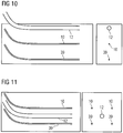
- FIGS. 9 to 11 Now show embodiments in which the conductors 10 are not formed as a unit with the fluid guide 12 but are laid separately.
- the conductor 10 and the production pipe 39 are again routed horizontally in the deposit. Furthermore, a production pipe 39 is arranged substantially vertically below the conductor 10.
- the fluid guide 12 is for example guided vertically into the deposit, wherein preferably a plurality of fluid guides 12 may be provided at intervals to each other.
- the solvent is transported via the fluid guides 12 in the vertical direction into the reservoir, wherein the solvent can preferably emerge only at one end piece of the respective fluid guide 12. This tail is positioned in a preferred embodiment at a certain distance from the conductor 10 vertically above the conductor 10.
- FIG. 10 shows an embodiment in which the conductor 10, the production tube 39 and the fluid guide 12 are formed as separate components, but are formed in their spatial orientation substantially uniform. All components are essentially horizontal within the deposit.
- the fluid guide 12 is perpendicular above the conductor 10, which in turn is arranged vertically above the production pipe 39.
- FIG. 11 shows again an embodiment in which the conductor 10, the production tube 39 and the fluid guide 12 are formed as separate components and are formed in their spatial orientation substantially uniform, with all components within the deposit substantially horizontal.
- the conductor loop is designed as a pair of conductors, wherein the conductors 10 of the pair of conductors are arranged substantially in a horizontal plane.
- There are two production pipes 39 are provided, which are preferably also arranged in a horizontal plane, wherein a respective one of the production pipes 39 is arranged substantially vertically below one of the conductors 10.
- the fluid guide 12 is located in this embodiment in a central region between the conductors 10 and the production pipes 39, below the ladder 10, above the production pipes 39, and substantially centrally between the conductor pairs or production pipe pairs.
- the injection of the solvent is preferably continuous, with no time interruption.
- the injection of the Solvent may also be used as needed for the preconditioning of the deposit, eg, the injection takes place prior to the actual operative production process to reduce the viscosity of the oil in the vicinity of the production tubing. Thus, the energy consumption of any pre-heating of the deposit is reduced or even avoided.
Description
Die Erfindung betrifft eine Anlage zur In-Situ-Gewinnung einer kohlenstoffhaltigen Substanz aus einer unterirdischen Lagerstätte unter Herabsetzung von deren Viskosität. Eine solche Vorrichtung dient insbesondere zur Förderung von Bitumen oder Schwerstöl aus einem Reservoir unter einem Deckgebirge, wie es bei Ölschiefer und/oder Ölsandvorkommen beispielsweise in Kanada gegeben ist.The invention relates to an installation for the in situ recovery of a carbonaceous substance from an underground deposit with reduction of its viscosity. Such a device is used in particular for the production of bitumen or heavy oil from a reservoir under an overburden, as is the case with oil shale and / or oil sand deposits, for example in Canada.
Zur Förderung von Schwerstölen oder Bitumen aus den bekannten Ölsand- oder Ölschiefervorkommen muss deren Fließfähigkeit erheblich erhöht werden. Dies kann durch Temperaturerhöhung des Vorkommens (Reservoirs) erreicht werden.For the promotion of heavy oils or bitumen from the known oil sand or oil shale deposits their flowability must be significantly increased. This can be achieved by increasing the temperature of the reservoir.
Das am weitesten verbreitete und angewendete In-Situ-Verfahren zur Förderung von Bitumen oder Schwerstöl ist das SAGD(Steam Assisted Gravity Drainage)-Verfahren. Dabei wird Wasserdampf unter hohem Druck durch ein innerhalb des Flözes horizontal verlaufendes Rohr eingepresst. Das aufgeheizte, geschmolzene und vom Sand oder Gestein abgelöste Bitumen oder Schwerstöl sickert zu einem zweiten etwa 5 m tiefer gelegenem Rohr, durch das die Förderung des verflüssigten Bitumens oder Schwerstöl erfolgt, wobei der Abstand von Injektor und Produktionsrohr abhängig von Reservoirgeometrie ist.The most widely used and applied in-situ process for the extraction of bitumen or heavy oil is the SAGD (S team A ssisted G ravity D rainage) process. In this case, water vapor is injected under high pressure through a tube running horizontally within the seam. The heated, molten bitumen or heavy oil removed from the sand or rock seeps to a second pipe located about 5 m lower, through which the liquefied bitumen or heavy oil is conveyed, the distance between injector and production pipe being dependent on reservoir geometry.
Der Wasserdampf hat dabei mehrere Aufgaben gleichzeitig zu erfüllen, nämlich die Einbringung der Heizenergie zur Verflüssigung, das Ablösen vom Sand sowie den Druckaufbau im Reservoir, um einerseits das Reservoir geomechanisch für Bitumentransport durchlässig zu machen (Permeabilität) und andererseits die Förderung des Bitumens ohne zusätzliche Pumpen zu ermöglichen.The steam has to fulfill several tasks at the same time, namely the introduction of heating energy for liquefaction, the detachment of the sand and the pressure build-up in the reservoir, on the one hand to make the reservoir geomechanically permeable for bitumen transport (permeability) and on the other hand, the promotion of bitumen without additional pumps to enable.
Das SAGD-Verfahren startet, indem für beispielsweise drei Monate durch beide Rohre Dampf eingebracht wird, um zunächst möglichst schnell das Bitumen im Raum zwischen den Rohren zu verflüssigen. Danach erfolgt die Dampfeinbringung nur noch durch das obere Rohr und die Förderung durch das untere Rohr kann beginnen.The SAGD process starts by introducing steam through both pipes, for example for three months, in order first to liquefy the bitumen in the space between the pipes as quickly as possible. Thereafter, the steam is introduced only through the upper tube and the promotion through the lower tube can begin.
In der deutschen Patentanmeldung
Bei den älteren, deutschen Patentanmeldungen
Bei den vorbeschriebenen Einrichtungen muss immer die elektrische Energie über einen elektrischen Hinleiter und einen elektrischen Rückleiter geführt werden. Dazu ist ein nicht unerheblicher Aufwand notwendig.In the above-described devices, the electrical energy must always be passed through an electrical forward conductor and an electrical return conductor. This requires a considerable effort.
Bei den genannten älteren Patentanmeldungen werden einzelne Induktorpaare aus Hin- und Rückleiter oder Gruppen von Induktorpaaren in verschiedenen geometrischen Konfigurationen bestromt, um das Reservoir induktiv zu erhitzen. Dabei wird innerhalb des Reservoirs von einem konstanten Abstand der Induktoren ausgegangen, was bei homogener elektrischer Leitfähigkeitsverteilung zu einer konstanten Heizleistung entlang der Induktoren führt. Beschrieben sind die räumlich eng beieinander geführten Hin- und Rückleiter in den Abschnitten, in denen das Deckgebirge durchstoßen wird, um dort die Verluste zu minimieren.In the said earlier patent applications, individual inductor pairs of forward and return conductors or groups of inductor pairs in different geometric configurations are energized to inductively heat the reservoir. In this case, a constant distance of the inductors is assumed within the reservoir, resulting in a homogeneous electrical conductivity distribution to a constant heat output along the inductors. Described are the spatially In the sections where the overburden is pierced, in order to minimize the losses, there is a direct return route.
Eine Variation der Heizleistung entlang der Induktoren kann, wie in den älteren Anmeldungen beschrieben, speziell durch abschnittsweise Injektion von Elektrolyten erfolgen, womit die Impedanz verändert wird. Dies setzt entsprechend Elektrolytinjektionsvorrichtungen voraus, deren Installation aufwendig oder kostspielig sein kann.A variation of the heating power along the inductors can, as described in the earlier applications, be carried out specifically by sectionwise injection of electrolytes, whereby the impedance is changed. This requires corresponding electrolyte injection devices whose installation can be complicated or costly.
Aus der Patentanmeldung
Davon ausgehend ist es Aufgabe der Erfindung, die vorbeschriebene Einrichtung für eine induktive Beheizung eines Reservoirs weiter zu optimieren.On this basis, it is an object of the invention to further optimize the above-described device for inductive heating of a reservoir.
Die Aufgabe wird erfindungsgemäß durch die Merkmale der unabhängigen Patentansprüche gelöst. Vorteilhafte Weiterbildungen und Ausgestaltungen der Erfindung sind in den Unteransprüchen angegeben.The object is achieved by the features of the independent claims. Advantageous developments and refinements of the invention are specified in the subclaims.
Erfindungsgemäß ist eine Vorrichtung und Verfahren zur Förderung von einer kohlenwasserstoffhaltigen Substanz, insbesondere Bitumen oder Schwerstöl, aus einem Reservoir vorgesehen, wobei das Reservoir mit Wärmeenergie zur Verringerung der Viskosität der Substanz beaufschlagbar ist, wozu wenigstens eine Leiterschleife zur induktiven Bestromung als elektrische und/oder elektromagnetische Heizung vorgesehen ist. Zusätzlich ist eine Fluidführung zum Transportieren und Einleiten eines Lösungsmittel-Fluids - im Folgenden auch kurz lediglich als "Fluid" bezeichnet - ins Reservoir vorgesehen, zum Zweck der weiteren Verringerung der Viskosität der Substanz und/oder ihrer Verdrängung aus dem Reservoir. Die Fluidführung ist perforiert, so dass bei Zuführung des Lösungsmittel-Fluids das Lösungsmittel-Fluid über eine Perforation aus der Fluidführung in das Reservoir eindringt. Weiterhin weist die Perforation Löcher auf, die in Form und/oder Größe und/oder Verteilung derart ausgestaltet sind, dass bei Zuführung des Lösungsmittel-Fluids unter vorgegebenem Druck das Lösungsmittel-Fluid verteilt über eine Länge der Fluidführung durch die Perforation in eine Umgebung der Fluidführung ins Reservoir abgegeben wird.According to the invention, a device and method for conveying a hydrocarbon-containing substance, in particular bitumen or heavy oil, are provided from a reservoir, wherein the reservoir can be acted upon by heat energy for reducing the viscosity of the substance, for which purpose at least one conductor loop for inductive energization as electrical and / or electromagnetic Heating is provided. In addition, a fluid guide for transporting and introducing a solvent fluid - hereinafter also referred to as "fluid" for short - is provided in the reservoir for the purpose of further reducing the viscosity of the substance and / or displacing it from the reservoir. The fluid guide is perforated, so that when the solvent fluid is supplied, the solvent fluid enters the reservoir via a perforation from the fluid guide. Furthermore, the perforation has holes which are designed in shape and / or size and / or distribution such that upon supply of the solvent fluid under a predetermined pressure, the solvent fluid distributed over a length of the fluid guide through the perforation in an environment of the fluid guide is discharged into the reservoir.
Erfindungsgemäß handelt es sich also um eine "in-situ"-Förderung, also die Förderung der kohlenwasserstoffhaltigen Substanz direkt aus dem Reservoir, in dem diese Substanz angereichert ist, ohne das Reservoir im Tagebau abzubauen. Als Reservoir versteht man vorzugsweise eine Ölsand-Lagerstätte, die unterirdisch zu finden ist.According to the invention, it is therefore an "in situ" promotion, ie the promotion of the hydrocarbonaceous substance directly from the reservoir in which this substance enriched without mining the reservoir in the opencast mine. As a reservoir is preferably understood an oil sands deposit that can be found underground.
Erfindungsgemäß ist keine Einbringung von Wasserdampf zum bloßen Erwärmen des Reservoirs vorgesehen. Es erfolgt jedoch ein Injizieren von Lösungsmitteln, wobei das Lösungsmittel-Fluid als Gas, als Flüssigkeit oder als Mehrkomponenten- bzw. Mehrphasengemisch ausgebildet sein kann.According to the invention, no introduction of water vapor for merely heating the reservoir is provided. However, there is an injection of solvents, wherein the solvent fluid may be formed as a gas, as a liquid or as a multi-component or multi-phase mixture.
Bei der Leiterschleife handelt es sich im Wesentlichen um ein verdrilltes Kabel, dass üblicherweise von einer röhrenförmigen Hülle ummantelt ist. Ein Abschnitt der Leiterschleife entlang der Erstreckung des Kabels wird im Folgenden als Leiter bezeichnet. Als Leiter wird insbesondere ein serieller Resonanzkreis oder ein Teil davon verstanden, welcher in einem kabelartigen Aufbau mit äußerer Isolierung gebracht wird. Diese kann in einer vorteilhaften Ausgestaltung der Erfindung von einer Fluidführung umgeben sein, mittels der das Lösungsmittel-Fluid ins Reservoir injiziert wird. Alternativ kann die Fluidführung für das Lösungsmittel-Fluid getrennt von der Leiterschleife implementiert sein.The conductor loop is essentially a twisted cable, usually encased in a tubular sheath. A section of the conductor loop along the extension of the cable is referred to below as a conductor. As a conductor, in particular a serial resonant circuit or a part thereof is understood, which is brought in a cable-like structure with external insulation. In an advantageous embodiment of the invention, this can be surrounded by a fluid guide, by means of which the solvent fluid is injected into the reservoir. Alternatively, the fluid guide for the solvent fluid may be implemented separately from the conductor loop.
Die Fluidführung ist ein ausgedehnter hohler Körper - beispielsweise ein Rohr oder ein Schlauch -, durch den das Lösungsmittel-Fluid transportiert wird.The fluid guide is an extended hollow body, such as a tube or hose, through which the solvent fluid is transported.
Durch das Vorsehen einer Fluidführung kann das Lösungsmittel-Fluid in das Reservoir geleitet werden. Je nach Ausgestaltung der Fluidführung können sich dadurch folgende Vorteile ergeben:
- i) Verringerung der Viskosität der zu fördernden kohlenwasserstoffhaltigen Substanz - das Bitumen oder das Schweröl - im Reservoir mittels Einleiten des Lösungsmittel-Fluids in das Reservoir.
- ii) Erhöhte Verdrängung der kohlenwasserstoffhaltigen Substanz, z.B. des Öls, durch das Einleiten des Fluids in das Reservoir.
- Punkt i) ist deshalb vorteilhaft, als dass eine Verringerung der Viskosität des Öls eine ökonomisch sinnvolle Förderung des Öls erst ermöglicht. Die induktive Beheizung sowie das Einleiten des Lösungsmittels bewirkt beides eine Verringerung der Viskosität.
- Zu Punkt ii): Ein weiteres Problem beim elektromagnetischen induktiven Heizen ist häufig die mangelnde oder unzureichende Verdrängung des Öls aus der Lagerstätte während der Förderung, was die Förderrate beeinträchtigen oder sogar die Förderung zum Stillstand bringen kann. Die Ölverdrängung beim SAGD-Verfahren nach dem Stand der Technik erfolgt durch die Ausdehnung der Wasserdampfkammer in der Lagerstätte. Beim erfindungsgemäß vorgesehenen elektromagnetischen induktiven Heizen ist eine Einbringung von Wasserdampf nicht vorgesehen. Jedoch kann das eingebrachte Lösungsmittel-Fluid selbst zur Verdrängung des Öls verwendet werden.
- i) reducing the viscosity of the hydrocarbonaceous substance to be delivered - the bitumen or heavy oil - in the reservoir by introducing the solvent fluid into the reservoir.
- ii) Increased displacement of the hydrocarbonaceous substance, eg of the oil, by introducing the fluid into the reservoir.
- Item i) is therefore advantageous in that a reduction in the viscosity of the oil makes economically viable delivery of the oil possible. The inductive heating and the introduction of the solvent causes both a reduction in viscosity.
- On point (ii): Another problem with electromagnetic inductive heating is often the lack or inadequate displacement of the oil from the reservoir during production, which may affect the production rate or even stop the production. The oil displacement in the SAGD method according to the prior art is carried out by the expansion of the steam chamber in the deposit. When inventively provided electromagnetic inductive heating, a contribution of water vapor is not provided. However, the introduced solvent fluid itself can be used to displace the oil.
Gemäß der Erfindung kommen als Lösemittel sowohl Gase - beispielsweise Ethan, Propan, Butan, CO2, SO2, usw. - als auch Flüssigkeiten - z.B. Polymere oder Wassergemische mit Polymeren (Polyacrylamide, Xanthan)- oder Wassergemische mit Beimischung von Netzmitteln (z. B. Tenside) in Frage, die sich jeweils in dem Bitumen der Lagerstätte lösen und dessen Viskosität verringern. Außerdem können die Lösemittel kombiniert bzw. gemischt werden - beispielsweise kann Propan als Lösemittel gemischt mit anderen Gasen (z.B. Methan) verwendet werden -, um den für die Verdrängung des Öls benötigten Volumenstrom und Druck zu gewährleisten.According to the invention come as solvents both gases - such as ethane, propane, butane, CO 2 , SO 2 , etc. - as well as liquids - eg polymers or water mixtures with polymers (polyacrylamides, xanthan) - or water mixtures with admixture of wetting agents (eg. As surfactants) in question, which each solve in the bitumen of the deposit and reduce its viscosity. In addition, the solvents can be combined or mixed - for example, propane can be used as a solvent mixed with other gases (eg methane) - to ensure the volume flow and pressure required for the displacement of the oil.
In einer ersten vorteilhaften Ausgestaltung können die Leiterschleife - auch als Induktor bezeichnet - und Fluidführung - im Weiteren auch als Injektor bezeichnet - getrennt ausgebildet sein. Eine oder mehrere Fluidführungen enden im Reservoir und sind derart ausgebildet, dass das Lösungsmittel-Fluid - das Solvent - ins Reservoir eindringen kann. Die Verlegung des Injektors ist sowohl in vertikaler als auch horizontaler Bohrung möglich. Dabei kann der Injektor unterschiedliche Positionen im Bezug auf den Induktor und ein Produktionsrohr haben, z.B. oberhalb des Induktors oder zwischen Paaren von Induktor und Produktionsrohr.In a first advantageous embodiment, the conductor loop - also referred to as an inductor - and fluid guide - hereinafter also referred to as an injector - separated be educated. One or more fluid guides terminate in the reservoir and are configured such that the solvent fluid - the solvent - can enter the reservoir. The installation of the injector is possible both in vertical and horizontal drilling. In this case, the injector may have different positions with respect to the inductor and a production tube, for example above the inductor or between pairs of inductor and production tube.
Alternativ kann der Induktor und der Injektor auch koaxial kombiniert werden. Der Induktor kann in ein das Lösemittel führende Rohr - die Fluidführung - verlegt werden, zentral oder exzentrisch positioniert. Weiterhin kann ein Induktor aus mehreren Teileitern bestehen, wobei die Teilleiter des Induktors die Fluidführung umgeben, die für die Zufuhr des Lösemittels verwendet wird.Alternatively, the inductor and the injector can also be combined coaxially. The inductor can be placed in a solvent-carrying pipe - the fluid guide - positioned centrally or eccentrically. Furthermore, an inductor may consist of several partial conductors, wherein the partial conductors of the inductor surround the fluid guide, which is used for the supply of the solvent.
Vorteilhafterweise kann die Fluidführung als Schlauch und/oder Rohr ausgebildet sein, wobei ein Abschnitt der Leiterschleife - im Folgenden als Leiter bezeichnet - innerhalb des Schlauchs bzw. des Rohrs angeordnet ist, insbesondere so, dass bei Zuführung des Lösungsmittel-Fluids der Leiter vom Fluid umspült wird. Somit ist lediglich eine Bohrung zur Verlegung des Induktors und der Fluidführung nötig.Advantageously, the fluid guide may be formed as a tube and / or tube, wherein a portion of the conductor loop - hereinafter referred to as conductor - is disposed within the tube or the tube, in particular so that when supplied with the solvent fluid, the conductor flows around the fluid becomes. Thus, only one hole for the installation of the inductor and the fluid guide is necessary.
Insbesondere kann der Schlauch und/oder das Rohr in etwa koaxial - zentriert oder auch exzentrisch - zum Leiter angeordnet sein. Zur Fixierung des Leiters innerhalb des Schlauchs und/oder des Rohrs kann zumindest ein Steg innerhalb des Schlauchs bzw. des Rohrs vorgesehen sein. Entlang einer axialen Richtung des Schlauchs/Rohrs können wiederholt Stege vorgesehen sein, um die Lage des Leiters zu sichern. Alternativ kann ein Steg auch eine axiale Ausdehnung haben, die sich sogar in einer besonderen Ausgestaltung über die gesamte Länge des Schlauchs/Rohrs erstreckt.In particular, the tube and / or the tube can be arranged approximately coaxially-centered or eccentrically-to the conductor. For fixing the conductor within the tube and / or the tube, at least one web can be provided within the tube or the tube. Along an axial direction of the hose / tube may be repeatedly provided webs to secure the position of the conductor. Alternatively, a web can also have an axial extent, which even extends in a particular embodiment over the entire length of the hose / tube.
Bei einer weiteren koaxialen Ausführungsform kann sich die Fluidführung im Zentrum befinden und kann von einem röhrenförmigen, koaxialen Leiter umgeben. Vorteilhaft dabei ist, dass das Fluid im elektromagnetisch-feldfreien Inneren geführt wird, so dass auch ein elektrisch leitfähiges Fluid keine Erwärmung durch Wirbelströme erfährt.In another coaxial embodiment, the fluid guide may be in the center and may be surrounded by a tubular, coaxial conductor. The advantage here is that the fluid is conducted in the electromagnetic field-free interior, so that even an electrically conductive fluid undergoes no heating by eddy currents.
Alternativ dazu kann der Leiter innerhalb des Schlauchs bzw. des Rohrs auch frei beweglich angeordnet sein, d.h. der Leiter ist unzentriert im Schlauch bzw. im Rohr und auf Mittel zum Fixieren wird verzichtet.Alternatively, the conductor may also be freely movable within the tube or tube, i. the conductor is uncentered in the tube or in the tube and means for fixing is omitted.
In einer weiteren Ausgestaltung kann die Fluidführung als eine Vielzahl von Schläuchen und/oder Rohren ausgebildet sein. Weiterhin können eine Vielzahl von Kapillaren und/oder ein poröses Material vorgesehen sein, um das Fluid in der Fluidführung zu transportieren. Diese Varianten sind bevorzugt derart angeordnet, dass der Leiter von der Vielzahl von Schläuchen und/oder Rohren und/oder Kapillaren und/oder dem porösen Material umgeben ist, wobei vorzugsweise die Vielzahl von Schläuchen und/oder Rohren und/oder Kapillaren und/oder das poröse Material und der Leiter innerhalb einer gemeinsamen schlauchförmigen Außenhülle angeordnet sind. Diese genannten Mittel zur Führung des Fluids sind insbesondere alle parallel zueinander verlaufend oder verdrillt. Diese Ausgestaltungen können so verstanden werden, dass das Fluid nicht den Leiter direkt umfließt sondern Schläuche/Rohre werden von außen an den Leiter angebracht sind.In a further embodiment, the fluid guide may be formed as a plurality of hoses and / or tubes. Furthermore, a plurality of capillaries and / or a porous material may be provided to transport the fluid in the fluid guide. These variants are preferably arranged such that the conductor is surrounded by the plurality of tubes and / or tubes and / or capillaries and / or the porous material, wherein preferably the plurality of tubes and / or tubes and / or capillaries and / or the porous material and the conductor are arranged within a common tubular outer shell. These mentioned means for guiding the fluid are in particular all parallel to each other or twisted. These embodiments can be understood that the fluid does not flow around the head directly but hoses / pipes are attached to the outside of the head.
Vollständigkeitshalber sei erwähnt, dass auch ein umgekehrter Ansatz denkbar ist, dass sich ein Leiter aus einer Vielzahl an Teilleitern zusammensetzt und diese Teilleiter um die Fluidführung herum angeordnet werden können.For the sake of completeness, it should also be mentioned that a reverse approach is also conceivable in that a conductor is composed of a plurality of partial conductors and these partial conductors can be arranged around the fluid guide.
Gemäß der Erfindung ist die Fluidführung perforiert, so dass bei Zuführung eines Fluids das Fluid aus der Fluidführung durch die Perforation in das Reservoir eindringt bzw. eingeleitet wird. Unter Perforation sind beispielsweise Löcher oder Schlitze gemeint, die sich in einer Fluidführung befinden, so dass das Fluid aus dem Inneren der Fluidführung nach Außen in die Umgebung der Löcher oder Schlitze austreten kann. Neben den genannten Löcher und Schlitzen ist es auch möglich, dass die Fluidführung zumindest teilweise aus porösen Material oder Kapillaren besteht, so dass das Fluid durch diese Mittel an die Umgebung abgegeben werden kann.According to the invention, the fluid guide is perforated, so that when a fluid is supplied, the fluid from the fluid guide penetrates through the perforation into the reservoir or is initiated. By perforation is meant, for example, holes or slits located in a fluid guide so that the fluid can exit the interior of the fluid guide to the outside in the vicinity of the holes or slots. In addition to the holes and slots mentioned, it is also possible that the fluid guide at least partially consists of porous material or capillaries, so that the fluid can be discharged by these means to the environment.
Vorzugsweise kann die Perforation derart ausgebildet sein und/oder können Mittel vorgesehen sein, dass ein Eindringen von Festkörpern und/oder Sanden aus dem Reservoir im Wesentlichen verhindert wird.Preferably, the perforation may be formed and / or means may be provided to substantially prevent intrusion of solids and / or sands from the reservoir.
Vorzugsweise soll die Perforation derart ausgebildet sein, dass über die gesamte Länge der Fluidführung - abgesehen von der Zuführung von der Oberfläche zur Zielregion im Reservoir - in jedem Abschnitt die gleiche Menge an Fluid abgegeben wird.Preferably, the perforation should be designed such that over the entire length of the fluid guide - apart from the supply from the surface to the target region in the reservoir - in each section, the same amount of fluid is discharged.
Bei den zuvor beschriebenen Anordnungen, bei denen sich die Fluidführung vom Leiter umgeben ist, z.B. als eine Vielzahl von Teilleitern oder als koaxial Rohr, ist die Perforation vorzugsweise elektrisch isolierend auszuführen, um keine direkte elektrische Verbindung zwischen Leiter und Reservoir über das Fluid herzustellen.In the previously described arrangements in which the fluid guide is surrounded by the conductor, e.g. as a plurality of sub-conductors or as a coaxial tube, the perforation is preferably carried out to be electrically insulating so as not to establish a direct electrical connection between the conductor and the reservoir via the fluid.
Das Einleiten des Fluids in das Reservoir kann dabei die Viskosität im Reservoir verringern und/oder den Druck im Reservoir erhöhen.The introduction of the fluid into the reservoir can thereby reduce the viscosity in the reservoir and / or increase the pressure in the reservoir.
Weiterhin kann ein Druckerhöhungsmittel zum Erhöhen des Drucks des Fluids in der Fluidführung vorgesehen sein, insbesondere eine Pumpe, so dass mittels des Druckerhöhungsmittels eine Bewegung der Flüssigkeit in der Fluidführung erreicht wird und so dass mittels des Druckerhöhungsmittels das Fluid mit erhöhtem Druck in die Fluidführung eingeleitet werden kann. Mit der Pumpe soll insbesondere so viel Druck erzeugt werden, dass eine vorbestimmte Menge an Fluid über die Perforation in das Reservoir eindringt. Mit "erhöhtem Druck" ist somit gemeint, dass ein Umgebungsdruck im Reservoir überwunden werden soll. Der hydrostatische Druck im Reservoir in der Umgebung der Perforation sollte überschritten werden, damit das Fluid austreten kann, was beispielsweise mit einem Druck von 5000 hPa (5 bar) bis 50000 hPa (50 bar) erreicht werden kann.Furthermore, a pressure increasing means for increasing the pressure of the fluid may be provided in the fluid guide, in particular a pump, so that by means of the pressure increasing means, a movement of the liquid is achieved in the fluid guide and so introduced by means of the pressure increasing means, the fluid with increased pressure in the fluid guide can be. In particular, so much pressure is to be generated by the pump that a predetermined amount of fluid penetrates into the reservoir via the perforation. By "increased pressure" is thus meant that an ambient pressure in the reservoir should be overcome. The hydrostatic pressure in the reservoir in the vicinity of the perforation should be exceeded so that the fluid can escape, which can be achieved for example with a pressure of 5000 hPa (5 bar) to 50,000 hPa (50 bar).
Im Falle eines gasförmigen Fluids kann ein Kompressor eingesetzt werden, welcher ein oder mehrere Injektionsbohrungen und darin verlegten Fluidführungen speisen kann.
Die Erhöhung des Drucks im Reservoir ist insbesondere vorteilhaft, als dass dadurch die kohlenwasserstoffhaltigen Substanz im Reservoir besser verdrängt wird und/oder ein Unterdruck im Reservoir - aufgrund der Förderung der Substanz - vermieden wird.In the case of a gaseous fluid, a compressor can be used which can feed one or more injection bores and fluid ducts laid therein.
The increase in the pressure in the reservoir is particularly advantageous in that it better displaces the hydrocarbonaceous substance in the reservoir and / or avoids a negative pressure in the reservoir due to the delivery of the substance.
Vorzugsweise wird der über die Zuführung angewendete Druck auf das Fluid in der Fluidführung derart an eine vorgegebene Perforation angepasst, dass ein Austreten des Fluids durch die Perforation über einen längeren Anwendungszeitraum gewährleistet ist.Preferably, the pressure applied via the feed to the fluid in the fluid guide is adapted to a predetermined perforation such that leakage of the fluid through the perforation over a longer period of use is ensured.
Zur weiteren Erhöhung des Drucks im Reservoir kann ein Ventil eines Förderrohrs zum Wegführen der verflüssigten kohlenwasserstoffhaltigen Substanz aus dem Reservoir geschlossen werden und zu einem späteren Zeitpunkt, abhängig vom Erreichen einer vorgegebenen Zeitspanne oder vom Erreichen eines vorgegebenen Drucks innerhalb des Reservoirs geöffnet werden. Somit kann während der Zeitspanne der Druck erhöht werden, weil kein Material das Reservoir verlässt und zusätzlich ein Fluid eingeleitet wird.To further increase the pressure in the reservoir, a valve of a production tubing for carrying the liquefied hydrocarbonaceous substance out of the reservoir may be closed and opened at a later time, depending on the attainment of a predetermined period of time or upon reaching a predetermined pressure within the reservoir. Thus, during the period of time the pressure can be increased because no material leaves the reservoir and additionally a fluid is introduced.
Im Falle der mangelnden Verdrängung bzw. um die Förderung der kohlenwasserstoffhaltigen Substanz aus dem Reservoir zu verbessern ist zusätzliche Einrichtung einer Pumpe in dem Förderrohr vorstellbar.In the case of lack of displacement or to the promotion of the hydrocarbonaceous substance from the reservoir to improve additional device of a pump in the delivery pipe is conceivable.
Vorzugsweise können für die Leiterschleife zwei voneinander getrennte Fluidführungen vorgesehen sein, jeweils für eine Hälfte der Leiterschleife, wobei die beiden Fluidführungen im Reservoir enden, so dass das Fluid vollumfänglich ins Reservoir eingebracht werden kann.Preferably, two separate fluid guides may be provided for the conductor loop, each for one half of the conductor loop, wherein the two fluid guides terminate in the reservoir, so that the fluid can be fully introduced into the reservoir.
Es wurde bereits erläutert, welche Zusammensetzung das Fluid haben kann, das in das Reservoir eingespeist wird. Hierbei ist es insbesondere vorteilhaft, wenn ein Teil des Fluids zumindest teilweise oder auch vollständig aus dem geförderten Wasser-Öl/Bitumen-Gemisch extrahiert wird, beispielsweise ein Erdgas oder Wasseranteile. Dazu sollte die gewünschte zu fördernde Substanz von dem geförderten Wasser-Öl/Bitumen-Gemisch abgetrennt werden und der gasförmige oder wässrige Rest nachbearbeitet bzw. aufbereitet werden. Dieser Rest kann anschließend wieder in das Reservoir eingebracht werden (d.h. entsprechend eines geschlossenen Kreislaufs).It has already been explained which composition may have the fluid that is fed into the reservoir. It is particularly advantageous if a portion of the fluid is at least partially or completely extracted from the funded water-oil / bitumen mixture, for example, a natural gas or water. For this purpose, the desired substance to be conveyed should be separated from the extracted water-oil / bitumen mixture and the gaseous or aqueous residue be post-processed or processed. This residue can then be reintroduced into the reservoir (i.e., according to a closed loop).
Die vorliegende Erfindung und deren Weiterbildungen werden nachfolgend im Rahmen eines Ausführungsbeispiels an Hand von Figuren näher erläutert.The present invention and its developments are explained below in the context of an embodiment with reference to figures.
Dabei zeigen in schematischer Darstellung
Figur 1- eine Vorrichtung zum Injizieren eines Fluids ins Reservoir;
- Figur 2
- eine perspektivische Darstellung eines Induktors mit Fluidführung;
Figur 3, 4, 5- Querschnitte von verschiedenen Induktoren mit Fluidführung;
Figur 6- einen perforierte Fluidführung;
- Figur 7-11
- verschiedene Ausgestaltungen der erfindungsgemäßen Vorrichtung.
- FIG. 1
- a device for injecting a fluid into the reservoir;
- FIG. 2
- a perspective view of an inductor with fluid guide;
- FIGS. 3, 4, 5
- Cross sections of different inductors with fluid guide;
- FIG. 6
- a perforated fluid guide;
- Figure 7-11
- Various embodiments of the device according to the invention.
Sich in den Figuren entsprechende Teile sind jeweils mit denselben Bezugszeichen versehen. Nicht näher ausgeführte Teile sind allgemein bekannter Stand der Technik.Parts corresponding to the figures are each provided with the same reference numerals. Non-detailed parts are well known in the art.
Gemäß
Die Vorrichtung zur In-Situ-Gewinnung einer kohlenwasserstoffhaltigen Substanz weist den genannten Induktor 10 auf, der in Bohrungen innerhalb der Lagerstätte 6 verläuft. Der Induktor 10 oder Abschnitte von diesem ist als Leiter anzusehen und bildet eine Leiterschleife. Die geschlossene Leiterschleife besteht aus den zwei horizontal in der Lagerstätte 6 verlaufenden Hin- und Rückleitern des Induktors 10, sowie aus Leiterstücken 11 die nicht oder wenig als Heizung wirken und oberirdisch verlaufen bzw. von der Erdoberfläche 5 hinein in die Lagerstätte 6 führen, um den Stromanschluss für den Induktor 10 zu gewährleisten. In der Figur sind beispielsweise beide Schleifenenden der Leiterschleife oberirdisch angeordnet. Auf der rechten Seite in der Figur wird die Schleife einfach geschlossen - siehe Leiterstück 11 in der Figur. Auf der linken Seite befindet sich eine Elektroversorgung 1 inklusive aller benötigten elektrischen Einrichtungen wie Umrichter und Generator, durch die der nötige Strom und die nötige Spannung an die Leiterschleife angelegt wird, damit die Induktoren 10 als Leiter für eine elektrische/elektromagnetische Heizung zur Wärmeerzeugung in der Lagestätte 6 dienen.The apparatus for in situ recovery of a hydrocarbonaceous substance has said
Die Induktoren 10 sind gegenüber zumindest Teilen der Lagerstätte 6 als induktive elektrische Heizung wirksam. Bedingt durch die Leitfähigkeit von zumindest Teilen der Lagerstätte 6, kann diese durch die weitgehend konzentrisch um die beiden möglichst parallel verlaufenden Abschnitte des Induktors 10 erwärmt werden.The
Bei dem Induktor 10 kann es sich insbesondere um stabförmige metallische Leiter oder um verdrillte metallische Kabel aus einem insbesondere gut leitfähigen Metall handeln, welche als Resonanzkreis ausgebildet werden.In particular, the
Nicht dargestellt ist eine Produktionsrohrleitung, über die die aus der Lagerstätte 6 extrahierte kohlenstoffhaltige Substanz gesammelt und aus der Lagerstätte 6 heraus bis an eine Erdoberfläche 5 gefördert wird.Not shown is a production pipeline, via which the carbonaceous substance extracted from the
Zur Verringerung der Viskosität der zu fördernden Substanz im Reservoir ist nun eine Vorrichtung vorgesehen, mittels der ein Lösungsmittel-Fluid ins Reservoir eingeleitet wird.To reduce the viscosity of the substance to be delivered in the reservoir, a device is now provided by means of which a solvent fluid is introduced into the reservoir.
Es liegt ein Vorratsbehälter 3 zum Bereitstellen eines Lösungsmittel-Fluids 14 - im Bild als Flüssigkeit angedeutet, jedoch kann es sich auch um ein Gas, um ein Mehrkomponentengasgemisch oder um ein Phasengemisch handeln, das als zu injizierendes Fluid vorgesehen ist. Dieses Fluid 14 wird mittels der Pumpe 2 - bzw. im Falle eines gasförmigen Fluids mittels eines Kompressors - in ein Fluidsystem eingeleitet, dass aus Fluideinleitungen 13 und aus einer Fluidführung 12 besteht. Die Fluidführung 12 soll hierbei die horizontal und parallel in der Lagerstätte 6 verlaufenden Abschnitte des Fluidsystems bezeichnen. Die Fluideinleitungen 13 umfasst gemäß der Figur das Schlauch-/Rohrsystem oberhalb der Erdoberfläche 5 bzw. die Verbindung zur horizontal verlaufenden Fluidführung 12.There is a reservoir 3 for providing a solvent fluid 14 - indicated in the figure as a liquid, but it may also be a gas, a multi-component gas mixture or a phase mixture, which is provided as a fluid to be injected. This fluid 14 is introduced by means of the pump 2 - or in the case of a gaseous fluid by means of a compressor - in a fluid system that from
Die Zuführung erfolgt im vorliegenden Beispiel im Unterschied zu
Gemäß der Figur ist die Leiterschleife entlang der Länge des Induktors 10 fast vollständig durch die Fluidführung 12 koaxial ummantelt, so dass der Induktor 10 - bzw. eine Ummantelung des Induktors 10 - im Betrieb vom Fluid umgeben ist. Idealerweise ist der Induktor 10 in die Fluidführung 12 integriert und kann als eine Einheit verlegt werden. Verschiedene Ausgestaltungen von derartigen kombinierten Leitern und Fluidführungen wird später an Hand der
Im Betrieb wird das Fluid mittels einer Pumpe 2 oder einer ähnlich wirkenden Vorrichtung ins Fluidsystem eingeleitet. Der Druck bleibt bis zum perforierten Teil der Fluidführung 12 im Wesentlichen unverändert bestehen, da bis zum Beginn der Fluidführung 12 kein Fluidauslass vorgesehen ist. Erreicht nun das zugeführte Fluid den Abschnitt mit der erfindungsgemäßen perforierten Fluidführung 12, wird ein Teil des Fluids über die Perforation 21 in die Lagerstätte 6 eingeleitet. Ein weiterer Teil des Fluids fließt weiter entlang der Fluidführung 12, wobei abschnittsweise stets ein Teil des Fluids über die Perforation 21 abgegeben wird. Es ergibt sich somit eine Verringerung des transportierten Fluids durch das austretende Fluid 22. Der Verlust an Fluid in der Fluidführung 12 wird mittels der Pumpe 2 ersetzt.In operation, the fluid is introduced into the fluid system by means of a pump 2 or similar device. The pressure remains essentially unchanged until the perforated part of the
Es ergeben sich insbesondere der Effekt, dass das Fluid im Umfeld der Induktoren 10 in die Lagerstätte 6 fließt, wodurch die Viskosität in der Lagerstätte 6 verringert wird und/oder der Druck in der Lagerstätte 6 erhöht wird. Insbesondere kann ein nachlassender Druck aufgrund der Förderung der kohlenwasserstoffhaltigen Substanz ausgeglichen werden. Weiterhin kann, je nach Zusammensetzung des Fluids, auch die elektrische Leitfähigkeit in der Lagerstätte 6 insbesondere im Umfeld der Induktoren 10 erhöht oder erniedrigt werden, was bei der Erhöhung wiederum die Effektivität der Induktoren 10 steigert. Bei Erniedrigung der Leitfähigkeit kann die Heizleistungsdichte in unmittelbarer Umgebung des Induktors 10 reduziert werden, um dessen thermische Belastung zu vermindern.This results in particular in the effect that the fluid flows in the vicinity of the
Der Abschluss 23, die Dimensionen der Fluidführung 12, die Ausgestaltung der Perforation 21 und der auf das Fluid über die Pumpe 2 angewendete Druck sollte bevorzugt so aneinander angepasst werden - insbesondere auch unter Beachtung der vorliegenden Gesteinsformationen und der Tiefe der Lagerstätte -, dass im wesentlichen über die gesamte Länge des horizontal verlaufenden Induktors 10 die genannten Effekte auftreten und/oder das Fluid 22 gleichmäßig in die Lagerstätte 6 austritt.The
Der angewendete Druck ist von der Tiefe der Lagerstätte, d.h. von der Distanz der horizontal verlegten Induktoren 10 zur Erdoberfläche 5, abhängig. Der Druck sollte höher als der hydrostatische Druck der entsprechenden Wassersäule sein und liegt beispielsweise im Bereich zwischen 5000 hPa (5 bar) bis 50000 hPa (50 bar).The pressure applied depends on the depth of the deposit, ie on the distance of horizontally routed
Druckentlastung in der Lagerstätte 6 wird vorgenommen, indem zu einem Zeitpunkt, bei dem der Druck auf ein oberhalb der Lagerstätte 6 vorliegendes Deckgebirge zu hoch wird, das/die Produktionsrohre - nicht dargestellt in
Zur Optimierung der Drücke können sogenannte "artificial lift pumps" eingesetzt werden, welche Einfluß auf den sogenannten "bottom whole"-Druck geben und mit denen der Transport des produzierten Mediums aus dem Reservoir durch die Produktionsrohre erfolgen kann.To optimize the pressures so-called "artificial lift pumps" can be used, which give influence on the so-called "bottom whole" pressure and with which the transport of the produced medium from the reservoir can be done through the production pipes.
Die Funktion des austretenden Fluids 22 ist somit sowohl die Erniedrigung der Viskosität, die Erhöhung oder Beibehaltung des Drucks in der Lagerstätte 6, als auch die Verdrängung - Ausschwemmung - der zu fördernden Substanz, wobei eine Vermeidung eines Unterdruckes in der Lagerstätte 6 erreicht wird.The function of the exiting
Als Lösungsmittel-Fluid kommen beispielsweise Gase - beispielsweise Ethan, Propan, Butan, CO2, SO2, usw. - als auch Flüssigkeiten - z.B. Polymere oder Wassergemische mit Polymeren - in Frage. Weiterhin sind Mehrkomponentengemische denkbar. Diese Lösungsmittel treten gemäß dem Verfahren ins Reservoir ein, lösen sich im Bitumen der Lagerstätte und verringern dessen Viskosität. Außerdem können die Lösemittel kombiniert bzw. gemischt werden - beispielsweise kann Propan als Lösemittel mit einem anderen Gas (z.B. Methan) verwendet werden -, um den für die Verdrängung des Öls benötigten Volumenstrom und Druck zu gewährleisten.As a solvent fluid, for example, gases - such as ethane, propane, butane, CO 2 , SO 2 , etc. - as well as liquids - eg polymers or water mixtures with polymers - in question. Furthermore, multicomponent mixtures are conceivable. These solvents enter the reservoir according to the process, dissolve in the bitumen of the reservoir and reduce its viscosity. In addition, the solvents can be combined or mixed - for example, propane can be used as a solvent with another gas (eg methane) - to ensure the volume flow and pressure required for the displacement of the oil.
In
Der Durchmesser des Induktors 10 kann bevorzugt 30 bis 100 mm betragen. Die Ringspaltweite des Induktors 10 wird vorzugsweise 5 mm bis 50 mm betragen.The diameter of the
Nachfolgend werden Querschnitte von mit einer Fluidführung kombinierten Leitern schematisch veranschaulicht. Der Querschnitt erfolgt entlang einer Schnittfläche, die rechtwinklig zur Erstreckung der Fluidführung gebildet wird.In the following, cross sections of conductors combined with a fluid guide will be schematically illustrated. The cross section takes place along a sectional surface which is formed at right angles to the extension of the fluid guide.
Gemäß
Die Fluidführung 12 ergibt sich aus den sich Hohlräumen innerhalb der Ummantelung 15.The
Die Breite der Stege 16 kann z.B. im Bereich 5-30 mm liegen, damit die Druckverluste des Fluids in der Fluidführung 12 nicht zu groß werden.The width of the
Nach
Gemäß
Während vorstehend bisher die reine Führung eines Fluids erläutert wurde, wird im Folgenden auf den weiteren wesentlichen Aspekt eingegangen, dass über die Fluidführung 12 das Fluid in die Lagerstätte 6 abgegeben wird. Beispielsweise über das Ende eines Injektors oder über die Länge der Fluidführung 12. Die in den
In
Analog zu
Die Löcher der Perforation 21 können dabei symmetrisch am gesamten Umfang der Ummantelung 15 angeordnet sein. Es könnte jedoch auch vorteilhaft sein, eine ungleichmäßige Verteilung vorzusehen. Auch über die Länge der Fluidführung 12 können sich die Verteilung und/oder die Ausgestaltung der Löcher ändern, insbesondere da sich der Druck innerhalb der Fluidführung 12 aufgrund des austretenden Fluids ändern kann.The holes of the
Ein austretendes Fluid in die Lagerstätte 6 in der Umgebung des Induktors 10 hat dabei insofern einen Vorteil, als dass dadurch auf diese Weise ein Lösemittel in das Reservoir injiziert werden kann, wodurch sich einerseits die Viskosität in der Lagerstätte 6 verringern kann und andererseits sich ein erhöhter Druck innerhalb der Lagerstätte 6 ergeben kann. Beide Effekte ergeben, dass die Förderquote und/oder die Fördergeschwindigkeit der zu fördernden kohlenwasserstoffhaltigen Substanz erhöht werden kann.An escaping fluid into the
In allen Ausgestaltungen der Erfindung - obwohl teilweise nicht dargestellt - ist ein Produktionsrohr zum Abtransportieren der zu fördernden Substanz im Erdreich vorhanden. Über das Produktionsrohr kann ein Produktionsstrom in Form eines Flüssigkeits-Feststoff-Gas-Gemischs - d.h. ein Phasengemisch - an die Erdoberfläche zur Aufbereitung transportiert werden. Im Folgenden werden verschiedene Ausgestaltungen an Hand von schematischen Figuren erläutert, die sich jeweils in der Anordnung der Induktoren, der Fluid-Injektoren und des Produktionsrohrs zueinander unterscheiden.In all embodiments of the invention - although not shown in part - a production pipe for removing the substance to be conveyed in the ground is present. Via the production pipe, a production stream in the form of a liquid-solid-gas mixture - ie a phase mixture - can be transported to the earth's surface for processing. In the following, various embodiments will be explained with reference to schematic figures, which differ from each other in the arrangement of the inductors, the fluid injectors and the production tube.
Gemäß
Die
Gemäß
Allen Ausgestaltungen haben gemeinsam, dass ein elektromagnetisch-induktives Heizen zur Erwärmung von Erdöllagerstätten unterstützt durch Injizieren von Lösemitteln eingesetzt wird.All configurations have in common that an electromagnetic-inductive heating is used to heat oil deposits supported by injecting solvents.
Die Injektion des Lösemittels ist vorzugsweise kontinuierlich, ohne zeitliche Unterbrechung. Die Injektion des Lösemittels kann nach Bedarf auch für die Vorkonditionierung der Lagerstätte verwendet werden, z.B. die Injektion erfolgt vor dem tatsächlichen, operativen Förderprozess um die Viskosität des Öls in der Nähe des Produktionsrohrs zu reduzieren. Damit wird der Energieverbrauch eines eventuell verwendeten Vorheizens der Lagerstätte reduziert oder sogar vermieden.The injection of the solvent is preferably continuous, with no time interruption. The injection of the Solvent may also be used as needed for the preconditioning of the deposit, eg, the injection takes place prior to the actual operative production process to reduce the viscosity of the oil in the vicinity of the production tubing. Thus, the energy consumption of any pre-heating of the deposit is reduced or even avoided.
Durch die Verwendung von Fluiden - gasförmigen oder flüssigen, einphasig oder als Mischung - zusätzlich zum induktiven Heizen, wird einerseits die Ölviskosität zusätzlich reduziert und anderseits eine Verdrängung des Öls aus der Lagerstätte ermöglicht. Der Gesamtenergieverbrauch für die Förderung des Öls oder Bitumens wird dadurch verringert. Dadurch dass auf das Einleiten von Wasserdampf verzichtet werden kann, ergeben sich ein geringerer Wasserverbrauch und weniger Anlagenaufwand zur Behandlung des produzierten Wassers. Weiterhin kann die schnellere Förderung oder eine höhere Förderquote erreicht werden.Through the use of fluids - gaseous or liquid, single phase or as a mixture - in addition to inductive heating, on the one hand, the oil viscosity is further reduced and on the other hand allows a displacement of the oil from the deposit. The total energy consumption for the extraction of the oil or bitumen is thereby reduced. The fact that it is possible to dispense with the introduction of water vapor, resulting in a lower water consumption and less investment costs for the treatment of the produced water. Furthermore, the faster funding or a higher funding rate can be achieved.
Claims (12)
- Device for extracting a hydrocarbon-containing substance, in particular bitumen or extra-heavy oil, from a reservoir (6), wherein thermal energy can be applied to the reservoir (6) in order to reduce the viscosity of the substance, for which purpose at least one conductor loop (10, 11) for inductively supplying electric current is provided as a means of electric and/or electromagnetic heating,
wherein a fluid conducting means (12) for transporting and introducing a solvent fluid into the reservoir (6) is provided for the purpose of further reducing the viscosity of the substance,
wherein the fluid conducting means (12) is perforated such that when the solvent fluid is supplied the solvent fluid permeates out of the fluid conducting means (12) into the reservoir (6) by way of a perforation (21), characterised in that the perforation (21) has holes which are embodied in terms of shape and/or size and/or distribution in such a way that when the solvent fluid is supplied under a predetermined pressure the solvent fluid is discharged in a distributed manner into the reservoir (6) over a length of the fluid conducting means (12) through the perforation (21) into an environment of the fluid conducting means (12). - Device according to claim 1,
characterised in that
a conductor (10) of the conductor loop (10, 11) consists of a plurality of subconductors which surround the fluid conducting means (12) in at least one section,
or
a conductor (10) of the conductor loop (10, 11) is surrounded by the fluid conducting means (12) in at least one section,
or
the conductor loop (10, 11) and the fluid conducting means (12) are separate components which are installed in different regions of the reservoir (6). - Device according to claim 2,
characterised in that
the fluid conducting means (12) is embodied as a tube and/or pipe, wherein- the conductor (10) is arranged inside the tube or pipe, in particular such that when the solvent fluid is supplied the solvent fluid flows around the conductor (10), or- the tube and/or pipe is arranged inside the conductor (10), or- the conductor (10) and the fluid conducting means (12) are embodied separately from each other. - Device according to claim 3,
characterised in that
the tube and/or pipe are arranged approximately coaxially with respect to the conductor (10). - Device according to one of claims 1 to 4,
characterised in that
the perforation (21) is embodied in such a way and/or means are provided so that an infiltration of solid bodies and/or sands from the reservoir (6) into the fluid conducting means (12) is substantially prevented. - Device according to one of claims 1 to 5,
characterised in that
in an embodiment of an internal fluid conducting means (12) and an external conductor (10) the perforation (21) is embodied in such a way that an electrical insulation of holes of the perforation (21) is provided with respect to the conductor (10). - Method for extracting a hydrocarbon-containing substance, in particular bitumen or extra-heavy oil, from a reservoir (6), wherein thermal energy is applied to the reservoir (6) in order to reduce the viscosity of the substance, for which purpose at least one conductor loop (10, 11) for inductively supplying current is provided as a means of electric and/or electromagnetic heating, wherein a solvent fluid is transported through a perforated fluid conducting means (12) into the reservoir (6) and is introduced into the reservoir (6) from the fluid conducting means (12) by way of a perforation (21) in order to further reduce the viscosity of the substance,
characterised in that the pressure of the solvent fluid is adjusted to the predetermined perforation (21) in such a way that when the solvent fluid is supplied under said pressure the solvent fluid is discharged into the reservoir (6) in a distributed manner over a length of the fluid conducting means (12) into an environment of the fluid conducting means (12). - Method according to claim 7,
characterised in that
a conductor (10) of the conductor loop (10, 11) is surrounded in at least one section by the fluid conducting means (12) through which the solvent fluid is conducted, the fluid conducting means (12) is perforated and the solvent fluid is conducted through a perforation (21) of the perforated fluid conducting means (12), wherein the fluid conducting means (12) is embodied in particular according to one of claims 1 to 6. - Method according to one of claims 7 or 8,
characterised in that
the solvent fluid is conducted under pressure into the fluid conducting means (12) such that a pressure greater than a pressure in the reservoir (6), preferably a hydrostatic pressure, is present inside the fluid conducting means (12) in the region of the perforation (21) in the environment of the perforation (21). - Method according to one of claims 7 to 9,
characterised in that
a gas or a liquid or a multicomponent mixture is provided as the solvent fluid, in particular comprising at least one of the constituents:- alkane, for example methane and/or propane and/or butane and/or ethane;- water mixtures with wetting agents contained therein, e.g. tensides;- water mixtures with polymers contained therein;- acids;- bases;- SO2;- CO2. - Method according to one of claims 7 to 10,
characterised in that
a valve of a producer well for conveying away the liquefied hydrocarbon-containing substance from the reservoir (6) is closed and opened again at a later time, dependent on a predetermined time interval having elapsed or on a predetermined pressure having been reached within the reservoir (6). - Method according to one of claims 7 to 11,
characterised in that
the electrical properties of the reservoir (6) are controlled, in particular the electrical conductivity is increased or alternatively reduced, through introducing the fluid into the reservoir (6).
Applications Claiming Priority (2)
| Application Number | Priority Date | Filing Date | Title |
|---|---|---|---|
| DE102010008779A DE102010008779B4 (en) | 2010-02-22 | 2010-02-22 | Apparatus and method for recovering, in particular recovering, a carbonaceous substance from a subterranean deposit |
| PCT/EP2010/068731 WO2011101055A2 (en) | 2010-02-22 | 2010-12-02 | Device and method for the recovery, in particular in situ recovery, of a carbonaceous substance from subterranean formations |
Publications (2)
| Publication Number | Publication Date |
|---|---|
| EP2510188A2 EP2510188A2 (en) | 2012-10-17 |
| EP2510188B1 true EP2510188B1 (en) | 2017-06-14 |
Family
ID=44356608
Family Applications (2)
| Application Number | Title | Priority Date | Filing Date |
|---|---|---|---|
| EP10788299.5A Not-in-force EP2510188B1 (en) | 2010-02-22 | 2010-12-02 | Device and method for the recovery, in particular in situ recovery, of a carbonaceous substance from subterranean formations |
| EP11701823.4A Not-in-force EP2507474B1 (en) | 2010-02-22 | 2011-01-31 | Device and method for obtaining, especially in situ, a carbonaceous substance from an underground deposit |
Family Applications After (1)
| Application Number | Title | Priority Date | Filing Date |
|---|---|---|---|
| EP11701823.4A Not-in-force EP2507474B1 (en) | 2010-02-22 | 2011-01-31 | Device and method for obtaining, especially in situ, a carbonaceous substance from an underground deposit |
Country Status (7)
| Country | Link |
|---|---|
| US (2) | US9322255B2 (en) |
| EP (2) | EP2510188B1 (en) |
| BR (2) | BR112012020949A2 (en) |
| CA (2) | CA2790597C (en) |
| DE (1) | DE102010008779B4 (en) |
| RU (2) | RU2587196C2 (en) |
| WO (2) | WO2011101055A2 (en) |
Families Citing this family (14)
| Publication number | Priority date | Publication date | Assignee | Title |
|---|---|---|---|---|
| DE102010023542B4 (en) | 2010-02-22 | 2012-05-24 | Siemens Aktiengesellschaft | Apparatus and method for recovering, in particular recovering, a carbonaceous substance from a subterranean deposit |
| EP2886793A1 (en) * | 2013-12-18 | 2015-06-24 | Siemens Aktiengesellschaft | Method for introducing an inductor loop into a rock formation |
| DE102014223621A1 (en) * | 2014-11-19 | 2016-05-19 | Siemens Aktiengesellschaft | deposit Heating |
| WO2017177319A1 (en) | 2016-04-13 | 2017-10-19 | Acceleware Ltd. | Apparatus and methods for electromagnetic heating of hydrocarbon formations |
| DE102016118282A1 (en) | 2016-09-27 | 2018-03-29 | Geo Exploration Solutions Fzc | Process for increasing the oil yield |
| US10669814B2 (en) * | 2017-08-08 | 2020-06-02 | Saudi Arabian Oil Company | In-situ heating fluids with electromagnetic radiation |
| CA3083568C (en) * | 2019-06-27 | 2021-07-06 | Eavor Technologies Inc. | Guidance method for multilateral directional drilling |
| WO2021081667A1 (en) * | 2019-11-01 | 2021-05-06 | 102062448 Saskatchewan Ltd | Processes and configurations for subterranean resource extraction |
| US11187044B2 (en) | 2019-12-10 | 2021-11-30 | Saudi Arabian Oil Company | Production cavern |
| WO2021258191A1 (en) * | 2020-06-24 | 2021-12-30 | Acceleware Ltd. | Methods of providing wellbores for electromagnetic heating of underground hydrocarbon formations and apparatus thereof |
| US11460330B2 (en) | 2020-07-06 | 2022-10-04 | Saudi Arabian Oil Company | Reducing noise in a vortex flow meter |
| RU201194U1 (en) * | 2020-08-04 | 2020-12-02 | Федеральное государственное бюджетное образовательное учреждение высшего образования "Тюменский индустриальный университет" (ТИУ) | HEATER |
| US11725504B2 (en) | 2021-05-24 | 2023-08-15 | Saudi Arabian Oil Company | Contactless real-time 3D mapping of surface equipment |
| US11619097B2 (en) | 2021-05-24 | 2023-04-04 | Saudi Arabian Oil Company | System and method for laser downhole extended sensing |
Family Cites Families (27)
| Publication number | Priority date | Publication date | Assignee | Title |
|---|---|---|---|---|
| US4037655A (en) | 1974-04-19 | 1977-07-26 | Electroflood Company | Method for secondary recovery of oil |
| US4010799A (en) * | 1975-09-15 | 1977-03-08 | Petro-Canada Exploration Inc. | Method for reducing power loss associated with electrical heating of a subterranean formation |
| US4084637A (en) * | 1976-12-16 | 1978-04-18 | Petro Canada Exploration Inc. | Method of producing viscous materials from subterranean formations |
| US4362610A (en) * | 1978-06-08 | 1982-12-07 | Carpenter Neil L | Apparatus for recovery of hydrocarbons from tar-sands |
| US4612989A (en) * | 1985-06-03 | 1986-09-23 | Exxon Production Research Co. | Combined replacement drive process for oil recovery |
| US5916529A (en) * | 1989-07-19 | 1999-06-29 | Chevron U.S.A. Inc | Multistage moving-bed hydroprocessing reactor with separate catalyst addition and withdrawal systems for each stage, and method for hydroprocessing a hydrocarbon feed stream |
| BR9005628C1 (en) | 1990-11-07 | 2000-01-25 | Petroleo Brasileiro Sa | Clearing method for flexible underwater lines. |
| RU2010954C1 (en) * | 1991-04-22 | 1994-04-15 | Татарский научно-исследовательский и проектный институт нефтяной промышленности | Induction heater |
| RU2139415C1 (en) * | 1998-01-21 | 1999-10-10 | Башкирский государственный университет | Method for recovery of minerals |
| RU2139416C1 (en) | 1998-03-18 | 1999-10-10 | Предприятие по добыче, переработке и транспортировке газа "Севергазпром" | Method for operational control of gas-lift well |
| CA2304938C (en) | 1999-08-31 | 2008-02-12 | Suncor Energy Inc. | Slanted well enhanced extraction process for the recovery of heavy oil and bitumen using heat and solvent |
| RU2200228C2 (en) * | 2001-04-20 | 2003-03-10 | Дрягин Вениамин Викторович | Down-hole induction heater |
| WO2002089532A1 (en) * | 2001-04-26 | 2002-11-07 | Phifer Smith Corporation | A method and apparatus for heating a gas-solvent solution |
| US6631761B2 (en) * | 2001-12-10 | 2003-10-14 | Alberta Science And Research Authority | Wet electric heating process |
| RU2231631C1 (en) * | 2002-12-15 | 2004-06-27 | Дыбленко Валерий Петрович | Method of development of an oil pool |
| US8101061B2 (en) * | 2004-03-05 | 2012-01-24 | Board Of Regents, The University Of Texas System | Material and device properties modification by electrochemical charge injection in the absence of contacting electrolyte for either local spatial or final states |
| ATE392536T1 (en) | 2004-04-23 | 2008-05-15 | Shell Int Research | PREVENTING SCABING EFFECTS IN DRILL HOLES |
| EP1780027A1 (en) | 2004-08-12 | 2007-05-02 | Sony Corporation | Print control device, printing device, print control method, program, and data structure |
| US20060131022A1 (en) * | 2004-12-17 | 2006-06-22 | Bj Services Company | Matrix treatment of damaged sandstone formations using buffered HF-acidizing solutions |
| US7398823B2 (en) * | 2005-01-10 | 2008-07-15 | Conocophillips Company | Selective electromagnetic production tool |
| DE102007040606B3 (en) | 2007-08-27 | 2009-02-26 | Siemens Ag | Method and device for the in situ production of bitumen or heavy oil |
| DE102007008292B4 (en) * | 2007-02-16 | 2009-08-13 | Siemens Ag | Apparatus and method for recovering a hydrocarbonaceous substance while reducing its viscosity from an underground deposit |
| CA2684486C (en) * | 2007-04-20 | 2015-11-17 | Shell Internationale Research Maatschappij B.V. | In situ recovery from residually heated sections in a hydrocarbon containing formation |
| DE102007036832B4 (en) | 2007-08-03 | 2009-08-20 | Siemens Ag | Apparatus for the in situ recovery of a hydrocarbonaceous substance |
| DE102007040605B3 (en) * | 2007-08-27 | 2008-10-30 | Siemens Ag | Device for conveying bitumen or heavy oil in-situ from oil sand deposits comprises conductors arranged parallel to each other in the horizontal direction at a predetermined depth of a reservoir |
| DE102008062326A1 (en) * | 2008-03-06 | 2009-09-17 | Siemens Aktiengesellschaft | Arrangement for inductive heating of oil sands and heavy oil deposits by means of live conductors |
| US8448707B2 (en) * | 2009-04-10 | 2013-05-28 | Shell Oil Company | Non-conducting heater casings |
-
2010
- 2010-02-22 DE DE102010008779A patent/DE102010008779B4/en not_active Expired - Fee Related
- 2010-12-02 US US13/579,400 patent/US9322255B2/en active Active
- 2010-12-02 RU RU2012140494/03A patent/RU2587196C2/en not_active IP Right Cessation
- 2010-12-02 BR BR112012020949A patent/BR112012020949A2/en not_active Application Discontinuation
- 2010-12-02 EP EP10788299.5A patent/EP2510188B1/en not_active Not-in-force
- 2010-12-02 CA CA2790597A patent/CA2790597C/en active Active
- 2010-12-02 WO PCT/EP2010/068731 patent/WO2011101055A2/en active Application Filing
-
2011
- 2011-01-31 BR BR112012020831A patent/BR112012020831A2/en not_active Application Discontinuation
- 2011-01-31 RU RU2012140479/03A patent/RU2586344C2/en not_active IP Right Cessation
- 2011-01-31 US US13/578,674 patent/US9574430B2/en not_active Expired - Fee Related
- 2011-01-31 EP EP11701823.4A patent/EP2507474B1/en not_active Not-in-force
- 2011-01-31 WO PCT/EP2011/051279 patent/WO2011101227A2/en active Application Filing
- 2011-01-31 CA CA2790616A patent/CA2790616C/en not_active Expired - Fee Related
Also Published As
| Publication number | Publication date |
|---|---|
| CA2790616C (en) | 2018-06-12 |
| DE102010008779A1 (en) | 2011-08-25 |
| BR112012020949A2 (en) | 2016-05-03 |
| CA2790597C (en) | 2018-03-06 |
| RU2012140479A (en) | 2014-03-27 |
| RU2587196C2 (en) | 2016-06-20 |
| DE102010008779B4 (en) | 2012-10-04 |
| BR112012020831A2 (en) | 2016-07-05 |
| WO2011101227A3 (en) | 2012-04-05 |
| CA2790616A1 (en) | 2011-08-25 |
| US9322255B2 (en) | 2016-04-26 |
| EP2507474A2 (en) | 2012-10-10 |
| WO2011101055A3 (en) | 2012-04-19 |
| US20150308248A1 (en) | 2015-10-29 |
| CA2790597A1 (en) | 2011-08-25 |
| US20130192831A1 (en) | 2013-08-01 |
| EP2507474B1 (en) | 2017-09-27 |
| RU2586344C2 (en) | 2016-06-10 |
| RU2012140494A (en) | 2014-03-27 |
| US9574430B2 (en) | 2017-02-21 |
| WO2011101227A2 (en) | 2011-08-25 |
| WO2011101055A2 (en) | 2011-08-25 |
| EP2510188A2 (en) | 2012-10-17 |
Similar Documents
| Publication | Publication Date | Title |
|---|---|---|
| EP2510188B1 (en) | Device and method for the recovery, in particular in situ recovery, of a carbonaceous substance from subterranean formations | |
| EP2122123B1 (en) | Method and device for the in-situ extraction of a hydrocarbon-containing substance, while reducing the viscosity thereof, from an underground deposit | |
| DE102010023542B4 (en) | Apparatus and method for recovering, in particular recovering, a carbonaceous substance from a subterranean deposit | |
| EP2315910B1 (en) | Installation for the<i> in situ </i>extraction of a substance containing carbon | |
| DE102007036832A1 (en) | Apparatus for the in situ recovery of a hydrocarbonaceous substance | |
| DE102008022176A1 (en) | Device for "in situ" production of bitumen or heavy oil | |
| EP2283208A1 (en) | Method and device for in-situ conveying of bitumen or very heavy oil | |
| DE2649488A1 (en) | PROCESS FOR THE RECOVERY OF VISCULAR PETROLEUM FROM UNDERGROUND STORES | |
| DE60221414T2 (en) | METHOD FOR BOHRLOCH LIQUID TREATMENT AND PUMP LINES THEREFOR | |
| EP2825715A2 (en) | Method and apparatus for introducing or sinking cavities in rock | |
| WO2014086594A1 (en) | Arrangement and method for introducing heat into a geological formation by means of electromagnetic induction | |
| EP2507471A2 (en) | Device and method for obtaining, especially in situ, a carbonaceous substance from an underground deposit | |
| DE3543827A1 (en) | OIL EXTRACTION PROCESS | |
| EP2633153B1 (en) | Process for the in situ extraction of bitumen or ultraheavy oil from oil sand deposits as reservoir | |
| DE3048179A1 (en) | METHOD AND DEVICE FOR THE EXTRACTION OF HIGH VISCOSEM OIL FROM SUBSTRATE GROUND INFORMATION | |
| DE102009036324A1 (en) | Geothermal probe mounting device | |
| DE3622203C2 (en) | ||
| WO2012062592A1 (en) | System and method for extraction of a gas from a gas-hydrate deposit | |
| DE1115663B (en) | Method and device for improving the production properties of an oil-bearing horizon | |
| EP2740809A1 (en) | Arrangement and method for inserting heat into a collection of ores and/or sands by electromagnetic induction |
Legal Events
| Date | Code | Title | Description |
|---|---|---|---|
| PUAI | Public reference made under article 153(3) epc to a published international application that has entered the european phase |
Free format text: ORIGINAL CODE: 0009012 |
|
| 17P | Request for examination filed |
Effective date: 20120706 |
|
| AK | Designated contracting states |
Kind code of ref document: A2 Designated state(s): AL AT BE BG CH CY CZ DE DK EE ES FI FR GB GR HR HU IE IS IT LI LT LU LV MC MK MT NL NO PL PT RO RS SE SI SK SM TR |
|
| RAP1 | Party data changed (applicant data changed or rights of an application transferred) |
Owner name: SIEMENS AKTIENGESELLSCHAFT |
|
| DAX | Request for extension of the european patent (deleted) | ||
| GRAP | Despatch of communication of intention to grant a patent |
Free format text: ORIGINAL CODE: EPIDOSNIGR1 |
|
| INTG | Intention to grant announced |
Effective date: 20170103 |
|
| GRAS | Grant fee paid |
Free format text: ORIGINAL CODE: EPIDOSNIGR3 |
|
| GRAA | (expected) grant |
Free format text: ORIGINAL CODE: 0009210 |
|
| AK | Designated contracting states |
Kind code of ref document: B1 Designated state(s): AL AT BE BG CH CY CZ DE DK EE ES FI FR GB GR HR HU IE IS IT LI LT LU LV MC MK MT NL NO PL PT RO RS SE SI SK SM TR |
|
| REG | Reference to a national code |
Ref country code: GB Ref legal event code: FG4D Free format text: NOT ENGLISH |
|
| REG | Reference to a national code |
Ref country code: CH Ref legal event code: EP Ref country code: AT Ref legal event code: REF Ref document number: 901155 Country of ref document: AT Kind code of ref document: T Effective date: 20170615 |
|
| REG | Reference to a national code |
Ref country code: IE Ref legal event code: FG4D Free format text: LANGUAGE OF EP DOCUMENT: GERMAN |
|
| REG | Reference to a national code |
Ref country code: DE Ref legal event code: R096 Ref document number: 502010013760 Country of ref document: DE |
|
| RAP2 | Party data changed (patent owner data changed or rights of a patent transferred) |
Owner name: SIEMENS AKTIENGESELLSCHAFT |
|
| REG | Reference to a national code |
Ref country code: CH Ref legal event code: NV Representative=s name: SIEMENS SCHWEIZ AG, CH Ref country code: CH Ref legal event code: PCOW Free format text: NEW ADDRESS: WERNER-VON-SIEMENS-STRASSE 1, 80333 MUENCHEN (DE) |
|
| REG | Reference to a national code |
Ref country code: NL Ref legal event code: MP Effective date: 20170614 |
|
| REG | Reference to a national code |
Ref country code: LT Ref legal event code: MG4D |
|
| PG25 | Lapsed in a contracting state [announced via postgrant information from national office to epo] |
Ref country code: ES Free format text: LAPSE BECAUSE OF FAILURE TO SUBMIT A TRANSLATION OF THE DESCRIPTION OR TO PAY THE FEE WITHIN THE PRESCRIBED TIME-LIMIT Effective date: 20170614 Ref country code: NO Free format text: LAPSE BECAUSE OF FAILURE TO SUBMIT A TRANSLATION OF THE DESCRIPTION OR TO PAY THE FEE WITHIN THE PRESCRIBED TIME-LIMIT Effective date: 20170914 Ref country code: LT Free format text: LAPSE BECAUSE OF FAILURE TO SUBMIT A TRANSLATION OF THE DESCRIPTION OR TO PAY THE FEE WITHIN THE PRESCRIBED TIME-LIMIT Effective date: 20170614 Ref country code: HR Free format text: LAPSE BECAUSE OF FAILURE TO SUBMIT A TRANSLATION OF THE DESCRIPTION OR TO PAY THE FEE WITHIN THE PRESCRIBED TIME-LIMIT Effective date: 20170614 Ref country code: GR Free format text: LAPSE BECAUSE OF FAILURE TO SUBMIT A TRANSLATION OF THE DESCRIPTION OR TO PAY THE FEE WITHIN THE PRESCRIBED TIME-LIMIT Effective date: 20170915 Ref country code: FI Free format text: LAPSE BECAUSE OF FAILURE TO SUBMIT A TRANSLATION OF THE DESCRIPTION OR TO PAY THE FEE WITHIN THE PRESCRIBED TIME-LIMIT Effective date: 20170614 |
|
| PG25 | Lapsed in a contracting state [announced via postgrant information from national office to epo] |
Ref country code: RS Free format text: LAPSE BECAUSE OF FAILURE TO SUBMIT A TRANSLATION OF THE DESCRIPTION OR TO PAY THE FEE WITHIN THE PRESCRIBED TIME-LIMIT Effective date: 20170614 Ref country code: BG Free format text: LAPSE BECAUSE OF FAILURE TO SUBMIT A TRANSLATION OF THE DESCRIPTION OR TO PAY THE FEE WITHIN THE PRESCRIBED TIME-LIMIT Effective date: 20170914 Ref country code: NL Free format text: LAPSE BECAUSE OF FAILURE TO SUBMIT A TRANSLATION OF THE DESCRIPTION OR TO PAY THE FEE WITHIN THE PRESCRIBED TIME-LIMIT Effective date: 20170614 Ref country code: LV Free format text: LAPSE BECAUSE OF FAILURE TO SUBMIT A TRANSLATION OF THE DESCRIPTION OR TO PAY THE FEE WITHIN THE PRESCRIBED TIME-LIMIT Effective date: 20170614 Ref country code: SE Free format text: LAPSE BECAUSE OF FAILURE TO SUBMIT A TRANSLATION OF THE DESCRIPTION OR TO PAY THE FEE WITHIN THE PRESCRIBED TIME-LIMIT Effective date: 20170614 |
|
| REG | Reference to a national code |
Ref country code: FR Ref legal event code: PLFP Year of fee payment: 8 |
|
| PG25 | Lapsed in a contracting state [announced via postgrant information from national office to epo] |
Ref country code: RO Free format text: LAPSE BECAUSE OF FAILURE TO SUBMIT A TRANSLATION OF THE DESCRIPTION OR TO PAY THE FEE WITHIN THE PRESCRIBED TIME-LIMIT Effective date: 20170614 Ref country code: SK Free format text: LAPSE BECAUSE OF FAILURE TO SUBMIT A TRANSLATION OF THE DESCRIPTION OR TO PAY THE FEE WITHIN THE PRESCRIBED TIME-LIMIT Effective date: 20170614 Ref country code: CZ Free format text: LAPSE BECAUSE OF FAILURE TO SUBMIT A TRANSLATION OF THE DESCRIPTION OR TO PAY THE FEE WITHIN THE PRESCRIBED TIME-LIMIT Effective date: 20170614 Ref country code: EE Free format text: LAPSE BECAUSE OF FAILURE TO SUBMIT A TRANSLATION OF THE DESCRIPTION OR TO PAY THE FEE WITHIN THE PRESCRIBED TIME-LIMIT Effective date: 20170614 |
|
| PGFP | Annual fee paid to national office [announced via postgrant information from national office to epo] |
Ref country code: FR Payment date: 20171214 Year of fee payment: 8 |
|
| PG25 | Lapsed in a contracting state [announced via postgrant information from national office to epo] |
Ref country code: IT Free format text: LAPSE BECAUSE OF FAILURE TO SUBMIT A TRANSLATION OF THE DESCRIPTION OR TO PAY THE FEE WITHIN THE PRESCRIBED TIME-LIMIT Effective date: 20170614 Ref country code: IS Free format text: LAPSE BECAUSE OF FAILURE TO SUBMIT A TRANSLATION OF THE DESCRIPTION OR TO PAY THE FEE WITHIN THE PRESCRIBED TIME-LIMIT Effective date: 20171014 Ref country code: SM Free format text: LAPSE BECAUSE OF FAILURE TO SUBMIT A TRANSLATION OF THE DESCRIPTION OR TO PAY THE FEE WITHIN THE PRESCRIBED TIME-LIMIT Effective date: 20170614 Ref country code: PL Free format text: LAPSE BECAUSE OF FAILURE TO SUBMIT A TRANSLATION OF THE DESCRIPTION OR TO PAY THE FEE WITHIN THE PRESCRIBED TIME-LIMIT Effective date: 20170614 |
|
| REG | Reference to a national code |
Ref country code: DE Ref legal event code: R097 Ref document number: 502010013760 Country of ref document: DE |
|
| PLBE | No opposition filed within time limit |
Free format text: ORIGINAL CODE: 0009261 |
|
| STAA | Information on the status of an ep patent application or granted ep patent |
Free format text: STATUS: NO OPPOSITION FILED WITHIN TIME LIMIT |
|
| PG25 | Lapsed in a contracting state [announced via postgrant information from national office to epo] |
Ref country code: DK Free format text: LAPSE BECAUSE OF FAILURE TO SUBMIT A TRANSLATION OF THE DESCRIPTION OR TO PAY THE FEE WITHIN THE PRESCRIBED TIME-LIMIT Effective date: 20170614 |
|
| PGFP | Annual fee paid to national office [announced via postgrant information from national office to epo] |
Ref country code: DE Payment date: 20180219 Year of fee payment: 8 |
|
| 26N | No opposition filed |
Effective date: 20180315 |
|
| REG | Reference to a national code |
Ref country code: CH Ref legal event code: PL |
|
| GBPC | Gb: european patent ceased through non-payment of renewal fee |
Effective date: 20171202 |
|
| PG25 | Lapsed in a contracting state [announced via postgrant information from national office to epo] |
Ref country code: SI Free format text: LAPSE BECAUSE OF FAILURE TO SUBMIT A TRANSLATION OF THE DESCRIPTION OR TO PAY THE FEE WITHIN THE PRESCRIBED TIME-LIMIT Effective date: 20170614 |
|
| REG | Reference to a national code |
Ref country code: IE Ref legal event code: MM4A |
|
| PG25 | Lapsed in a contracting state [announced via postgrant information from national office to epo] |
Ref country code: MT Free format text: LAPSE BECAUSE OF FAILURE TO SUBMIT A TRANSLATION OF THE DESCRIPTION OR TO PAY THE FEE WITHIN THE PRESCRIBED TIME-LIMIT Effective date: 20170614 Ref country code: LU Free format text: LAPSE BECAUSE OF NON-PAYMENT OF DUE FEES Effective date: 20171202 |
|
| REG | Reference to a national code |
Ref country code: BE Ref legal event code: MM Effective date: 20171231 |
|
| PG25 | Lapsed in a contracting state [announced via postgrant information from national office to epo] |
Ref country code: IE Free format text: LAPSE BECAUSE OF NON-PAYMENT OF DUE FEES Effective date: 20171202 |
|
| PG25 | Lapsed in a contracting state [announced via postgrant information from national office to epo] |
Ref country code: BE Free format text: LAPSE BECAUSE OF NON-PAYMENT OF DUE FEES Effective date: 20171231 Ref country code: CH Free format text: LAPSE BECAUSE OF NON-PAYMENT OF DUE FEES Effective date: 20171231 Ref country code: GB Free format text: LAPSE BECAUSE OF NON-PAYMENT OF DUE FEES Effective date: 20171202 Ref country code: LI Free format text: LAPSE BECAUSE OF NON-PAYMENT OF DUE FEES Effective date: 20171231 |
|
| REG | Reference to a national code |
Ref country code: AT Ref legal event code: MM01 Ref document number: 901155 Country of ref document: AT Kind code of ref document: T Effective date: 20171202 |
|
| PG25 | Lapsed in a contracting state [announced via postgrant information from national office to epo] |
Ref country code: AT Free format text: LAPSE BECAUSE OF NON-PAYMENT OF DUE FEES Effective date: 20171202 |
|
| PG25 | Lapsed in a contracting state [announced via postgrant information from national office to epo] |
Ref country code: MC Free format text: LAPSE BECAUSE OF FAILURE TO SUBMIT A TRANSLATION OF THE DESCRIPTION OR TO PAY THE FEE WITHIN THE PRESCRIBED TIME-LIMIT Effective date: 20170614 Ref country code: HU Free format text: LAPSE BECAUSE OF FAILURE TO SUBMIT A TRANSLATION OF THE DESCRIPTION OR TO PAY THE FEE WITHIN THE PRESCRIBED TIME-LIMIT; INVALID AB INITIO Effective date: 20101202 |
|
| REG | Reference to a national code |
Ref country code: DE Ref legal event code: R119 Ref document number: 502010013760 Country of ref document: DE |
|
| PG25 | Lapsed in a contracting state [announced via postgrant information from national office to epo] |
Ref country code: DE Free format text: LAPSE BECAUSE OF NON-PAYMENT OF DUE FEES Effective date: 20190702 Ref country code: CY Free format text: LAPSE BECAUSE OF NON-PAYMENT OF DUE FEES Effective date: 20170614 Ref country code: FR Free format text: LAPSE BECAUSE OF NON-PAYMENT OF DUE FEES Effective date: 20181231 |
|
| PG25 | Lapsed in a contracting state [announced via postgrant information from national office to epo] |
Ref country code: MK Free format text: LAPSE BECAUSE OF FAILURE TO SUBMIT A TRANSLATION OF THE DESCRIPTION OR TO PAY THE FEE WITHIN THE PRESCRIBED TIME-LIMIT Effective date: 20170614 |
|
| PG25 | Lapsed in a contracting state [announced via postgrant information from national office to epo] |
Ref country code: TR Free format text: LAPSE BECAUSE OF FAILURE TO SUBMIT A TRANSLATION OF THE DESCRIPTION OR TO PAY THE FEE WITHIN THE PRESCRIBED TIME-LIMIT Effective date: 20170614 |
|
| PG25 | Lapsed in a contracting state [announced via postgrant information from national office to epo] |
Ref country code: PT Free format text: LAPSE BECAUSE OF FAILURE TO SUBMIT A TRANSLATION OF THE DESCRIPTION OR TO PAY THE FEE WITHIN THE PRESCRIBED TIME-LIMIT Effective date: 20170614 |
|
| PG25 | Lapsed in a contracting state [announced via postgrant information from national office to epo] |
Ref country code: AL Free format text: LAPSE BECAUSE OF FAILURE TO SUBMIT A TRANSLATION OF THE DESCRIPTION OR TO PAY THE FEE WITHIN THE PRESCRIBED TIME-LIMIT Effective date: 20170614 |