EP2507474B1 - Device and method for obtaining, especially in situ, a carbonaceous substance from an underground deposit - Google Patents
Device and method for obtaining, especially in situ, a carbonaceous substance from an underground deposit Download PDFInfo
- Publication number
- EP2507474B1 EP2507474B1 EP11701823.4A EP11701823A EP2507474B1 EP 2507474 B1 EP2507474 B1 EP 2507474B1 EP 11701823 A EP11701823 A EP 11701823A EP 2507474 B1 EP2507474 B1 EP 2507474B1
- Authority
- EP
- European Patent Office
- Prior art keywords
- liquid
- reservoir
- conductor
- carrying conduit
- pressure
- Prior art date
- Legal status (The legal status is an assumption and is not a legal conclusion. Google has not performed a legal analysis and makes no representation as to the accuracy of the status listed.)
- Not-in-force
Links
Images


Classifications
-
- E—FIXED CONSTRUCTIONS
- E21—EARTH DRILLING; MINING
- E21B—EARTH DRILLING, e.g. DEEP DRILLING; OBTAINING OIL, GAS, WATER, SOLUBLE OR MELTABLE MATERIALS OR A SLURRY OF MINERALS FROM WELLS
- E21B43/00—Methods or apparatus for obtaining oil, gas, water, soluble or meltable materials or a slurry of minerals from wells
- E21B43/16—Enhanced recovery methods for obtaining hydrocarbons
- E21B43/24—Enhanced recovery methods for obtaining hydrocarbons using heat, e.g. steam injection
- E21B43/2401—Enhanced recovery methods for obtaining hydrocarbons using heat, e.g. steam injection by means of electricity
-
- C—CHEMISTRY; METALLURGY
- C09—DYES; PAINTS; POLISHES; NATURAL RESINS; ADHESIVES; COMPOSITIONS NOT OTHERWISE PROVIDED FOR; APPLICATIONS OF MATERIALS NOT OTHERWISE PROVIDED FOR
- C09K—MATERIALS FOR MISCELLANEOUS APPLICATIONS, NOT PROVIDED FOR ELSEWHERE
- C09K8/00—Compositions for drilling of boreholes or wells; Compositions for treating boreholes or wells, e.g. for completion or for remedial operations
- C09K8/58—Compositions for enhanced recovery methods for obtaining hydrocarbons, i.e. for improving the mobility of the oil, e.g. displacing fluids
- C09K8/592—Compositions used in combination with generated heat, e.g. by steam injection
-
- E—FIXED CONSTRUCTIONS
- E21—EARTH DRILLING; MINING
- E21B—EARTH DRILLING, e.g. DEEP DRILLING; OBTAINING OIL, GAS, WATER, SOLUBLE OR MELTABLE MATERIALS OR A SLURRY OF MINERALS FROM WELLS
- E21B17/00—Drilling rods or pipes; Flexible drill strings; Kellies; Drill collars; Sucker rods; Cables; Casings; Tubings
- E21B17/18—Pipes provided with plural fluid passages
-
- E—FIXED CONSTRUCTIONS
- E21—EARTH DRILLING; MINING
- E21B—EARTH DRILLING, e.g. DEEP DRILLING; OBTAINING OIL, GAS, WATER, SOLUBLE OR MELTABLE MATERIALS OR A SLURRY OF MINERALS FROM WELLS
- E21B34/00—Valve arrangements for boreholes or wells
- E21B34/06—Valve arrangements for boreholes or wells in wells
-
- E—FIXED CONSTRUCTIONS
- E21—EARTH DRILLING; MINING
- E21B—EARTH DRILLING, e.g. DEEP DRILLING; OBTAINING OIL, GAS, WATER, SOLUBLE OR MELTABLE MATERIALS OR A SLURRY OF MINERALS FROM WELLS
- E21B43/00—Methods or apparatus for obtaining oil, gas, water, soluble or meltable materials or a slurry of minerals from wells
- E21B43/30—Specific pattern of wells, e.g. optimizing the spacing of wells
- E21B43/305—Specific pattern of wells, e.g. optimizing the spacing of wells comprising at least one inclined or horizontal well
Definitions
- the invention relates to an installation for the in situ recovery of a carbonaceous substance from an underground deposit with reduction of its viscosity.
- a device is used in particular for the production of bitumen or heavy oil from a reservoir under an overburden, as is the case with oil shale and / or oil sand deposits, for example in Canada.
- SAGD S team A ssisted G ravity D rainage
- water vapor which may be added to the solvent, is pressed under high pressure through a tube extending horizontally within the seam.
- the heated, molten bitumen or heavy oil removed from the sand or rock seeps to a second pipe located about 5 m lower, through which the liquefied bitumen or heavy oil is conveyed, the distance between injector and production pipe being dependent on reservoir geometry.
- the steam has to fulfill several tasks at the same time, namely the introduction of heating energy for liquefaction, the detachment of the sand and the pressure build-up in the reservoir, on the one hand to make the reservoir geomechanically permeable for bitumen transport (permeability) and on the other hand, the promotion of bitumen without additional pumps to enable.
- the SAGD process starts by introducing steam through both pipes, for example for three months, in order first to liquefy the bitumen in the space between the pipes as quickly as possible. Thereafter, the steam is introduced only through the upper tube and the promotion through the lower tube can begin.
- German patent application DE 10 2007 008 292 A1 It is already stated that the SAGD method commonly used for this purpose can be completed with an inductive heating device. Furthermore, in the German patent application DE 10 2007 036 832 A1 a device described in the parallel inductor or electrode assemblies are present, which are connected above ground to an oscillator or inverter.
- German patent applications DE 10 2007 008 292 A1 and DE 10 2007 036 832 A1 So it is proposed to superimpose the steam input with an inductive heating of the deposit.
- resistive heating between two electrodes may additionally be carried out.
- a variation of the heating power along the inductors can, as described in the earlier applications, be carried out specifically by sectionwise injection of electrolytes, whereby the impedance is changed. This requires corresponding electrolyte injection devices whose installation can be complicated or costly.
- a device for conveying a hydrocarbon-containing substance, in particular bitumen or heavy oil is provided from a reservoir, wherein the Reservoir with heat energy to reduce the viscosity of the substance is acted on, including at least one conductor loop for inductive energization of the reservoir is provided as electrical / electromagnetic heating of the reservoir, wherein a conductor - an inductor - the conductor loop is surrounded in at least a portion of a liquid guide and the liquid guide is perforated, so that when a liquid is supplied, the liquid penetrates via a perforation from the liquid guide into the reservoir.
- the invention is therefore an "in situ” promotion, ie the promotion of the hydrocarbonaceous substance directly from the reservoir in which this substance is enriched without degrading the reservoir in the open pit.
- a reservoir is preferably understood an oil sands deposit that can be found underground.
- no introduction of steam via the liquid guide is provided.
- a combination may additionally be advantageous with the SAGD method, for example cooling the inductor according to the device according to the invention and introducing steam via a further tube or a further tube.
- the section of the conductor means a section of the conductor. Assuming that the conductor is essentially a twisted cable encased in a tubular sheath, the portion of the conductor means a section along the length of the cable and sheath.
- a conductor in particular a serial resonant circuit or a part thereof is understood, which is brought in a cable-like structure with external insulation. This is according to the invention surrounded by a liquid guide.
- the liquid guide is an extended hollow body - for example, a tube or a tube - to understand, can be transported through the liquid.
- the electrical conductivity in the immediate vicinity of the conductor can be reduced, thus reducing the geometry-related high heating power density directly at the conductor. It is thus possible to achieve a more homogeneous heating power density in the reservoir.
- the cooling is particularly advantageous for larger storage depths - about greater than 130 m - advantageous because otherwise it could lead to overheating of the inductor, for example, at temperatures of about 200 ° C or more.
- a plastic insulation of the inductor could not permanently withstand such a high temperature. It should be noted here that the boiling point of water in the reservoir at a depth of 130 m or more can be around 200 ° C.
- the heat of the conductor comprises heat due to ohmic losses in the conductor, but more importantly, the heat from the reservoir, which the conductor would receive from the reservoir without corresponding cooling from the environment, can be more significant.
- the inventive idea is based essentially on a fluid guide with a closed fluid circuit in which cool liquid flows along the conductor within the fluid guide, is heated in the reservoir and is led out of the reservoir again.
- the additional inventive concept is explained, in which additionally or alternatively to the cooling, the liquid is fed via the liquid guide into the reservoir and is distributed there in the ground, in order to achieve further effects - for example the improvement of the conductivity in the reservoir.
- the liquid guide and the conductor may be arranged to each other such that a liquid in the liquid guide causes cooling of the conductor. It is irrelevant whether it is the conductor's own waste heat or whether it is heat acting on the conductor from the outside, from the reservoir heated by the current-carrying conductor.
- the cooling effect can be enhanced by movement of the liquid, in particular along the conductor and with circulation or exchange of the liquid, since warm liquid is thereby conducted away and cool liquid can flow.
- the liquid guide may be part of a substantially closed liquid circuit, in which a means for heat exchange - in particular on the surface and not within the reservoir - is provided to cool a liquid heated within the liquid guide again ,
- the re-cooling of the liquid can be effected by tubes which pass through colder region of the reservoir, i.
- the liquid is not brought to the surface, but circulates only in the depth.
- the liquid guide may be formed as a tube and / or tube, wherein the conductor is disposed within the tube or the tube, in particular so that when supplied with a liquid, the conductor is surrounded by the liquid.
- the conductor is disposed within the tube or the tube, in particular so that when supplied with a liquid, the conductor is surrounded by the liquid.
- the tube and / or the tube can be arranged approximately coaxially centered to the conductor, wherein in particular at least one web within the tube or the tube for fixing or positioning of the conductor or for stabilizing the position of the conductor inside the tube or of the pipe is provided.
- a web can also have an axial extent, which even extends in a particular embodiment over the entire length of the hose / tube.
- the conductor may also be freely movable within the tube or tube, i. the conductor is uncentered in the tube or in the tube and means for fixing is omitted.
- the liquid guide may be formed as a plurality of hoses and / or tubes.
- a plurality of capillaries and / or a porous material may be provided to transport the liquid in the liquid guide.
- These variants are preferably arranged such that the conductor is surrounded by the plurality of tubes and / or tubes and / or capillaries and / or the porous material, wherein preferably the plurality of tubes and / or tubes and / or capillaries and / or the porous material and the conductor are arranged within a common tubular outer shell.
- These mentioned means for guiding the liquid are in particular all parallel to each other or twisted.
- a conductor is composed of a multiplicity of partial conductors and these partial conductors can be arranged around the fluid guide.
- the liquid guide in the form of the plurality of hoses and / or tubes may be formed such that at least a first tube and / or tube is provided, in which the liquid in opposite directions to a flow direction of the liquid in at least one second hose and / or pipe flows.
- a closed circuit can be formed.
- two bodies above ground liquid in the liquid guide are pumped from each of the two places only a subset of the available tubes or tubes are filled.
- a more homogeneous temperature along the conductor is achieved with an opposite cooling liquid guide.
- thermally insulating means In an extension can be arranged between the liquid guide and the reservoir, in particular between the liquid guide and the outer shell, thermally insulating means, wherein the thermally insulating means is in particular designed as an air- or gas-filled or as a vacuum-enclosing cavity.
- the thermal insulation of the liquid guide against the reservoir proves to be particularly advantageous, since in a suitable embodiment, the inductively introduced heating power is dissipated again only to the lowest possible proportion by the liquid cooling.
- a pressure increasing means for increasing the pressure of a liquid or for circulating the liquid may be provided, in particular a pump, so that by means of the pressure increasing means, a movement of the liquid is achieved in the liquid guide. In this way, a cooling circuit can be operated.
- thermosyphon - may be provided.
- a reservoir for the liquid in addition to the liquid guide and the pump may be in particular a reservoir for the liquid, a heat exchanger and other above-ground or underground hydraulic connections.
- the reservoir can be carried out either under atmospheric pressure or as a pressure vessel.
- a pressure holder may be provided by means of which the liquid is kept at a higher pressure level as a coolant is circulated and under high pressure level, to avoid boiling at high power input.
- the overall system has a return for the liquid to the surface.
- the invention is particularly advantageous when the liquid guide has a perforation, so that when a liquid is supplied, the liquid from the liquid guide can penetrate into the reservoir, and the perforation in turn has holes that configured in shape and / or size and / or distribution can be that when supplying a liquid under a predetermined pressure, the conductor over the entire length of the area surrounded by the liquid guide portion of the conductor loop is sufficiently cooled.
- liquid guide being sufficiently filled with liquid throughout the length and / or liquid heated by the conductor being led away from the liquid guide through the holes.
- a required amount of low temperature cooling liquid may flow through the liquid guide.
- the above-mentioned effect is preferably obtained when the pressure applied to the liquid in the liquid guide via the feed is adapted to a predetermined perforation in such a manner that leakage of the liquid through the perforation is ensured over a longer period of use.
- liquid conducted through the liquid guide system thermally insulates an environment in the reservoir and / or that the conductor is cooled by the liquid conducted through the liquid guide.
- Water may be provided as liquid for cooling, in particular desalted and / or descaled and / or mixed with an antifreeze agent - e.g. Glycol.
- an antifreeze agent e.g. Glycol.
- salt water, oil, emulsions or solutions may be provided.
- the basic form for the liquid may preferably be an extracted liquid which can be precipitated from the desired delivery material conveyed from the reservoir.
- the liquid guide is perforated, so that when a liquid is supplied, the liquid from the liquid guide penetrates or is introduced through the perforation into the reservoir.
- perforation is meant, for example, holes or slits located in a liquid guide, so that liquid can escape from the interior of the liquid guide to the outside in the vicinity of the holes or slots.
- the fluid guide consists at least partially of porous material or capillaries, so that the fluid can be released by these means to the environment.
- the introduction of the liquid into the reservoir can thereby increase the electrical conductivity of the reservoir and / or increase the pressure in the reservoir.
- a pressure increasing means can be provided for increasing the pressure of a liquid or for circulating the liquid, in particular a pump, so that a fluid with increased pressure can be introduced into the fluid guide by means of the pressure increasing means.
- so much pressure is to be generated by the pump that a predetermined amount of liquid penetrates into the reservoir via the perforation.
- increase pressure is thus meant that an ambient pressure in the reservoir should be overcome.
- the hydrostatic pressure in the reservoir in the vicinity of the perforation should be exceeded so that the liquid can escape, which can be achieved for example with a pressure of 10,000 hPa (10 bar) to 50,000 hPa (50 bar).
- the perforation may be formed and / or means may be provided for the penetration of solids and / or sands from the reservoir in the Is substantially prevented.
- Such agents are known, for example, by the term "Gravel Pack".
- the invention is particularly advantageous when the perforation has holes that can be configured in shape and / or size and / or distribution such that when a liquid is supplied under a predetermined pressure, the liquid distributed over a length of the liquid guide through the perforation into an environment the conductor loop is discharged in the reservoir, so that the electrical conductivity of the reservoir changes and / or the pressure in the reservoir is increased.
- the liquid can be controlled so that the electrical conductivity within the reservoir in its embedding is predominantly increased and / or that the electrical conductivity in the reservoir in the immediate vicinity of the conductor is lowered.
- the perforation should be designed so that the entire length of the liquid guide - except for the supply from the surface to the target region in the reservoir - delivered in each section the same amount of liquid.
- the increase in the pressure in the reservoir is particularly advantageous in that it better displaces the hydrocarbonaceous substance in the reservoir and / or avoids a negative pressure in the reservoir due to the delivery of the substance.
- water or an organic or inorganic solution as the electrolyte in particular also for increasing the conductivity, is suitable as the liquid to be supplied.
- the liquid may preferably have at least one of the following constituents: salts, weak acids, weak bases, CO 2 , or solvents which in particular contain alkanes, for example methane, propane, butane.
- a valve of a production tubing for carrying the liquefied hydrocarbonaceous substance out of the reservoir may be closed and opened at a later time, depending on the attainment of a predetermined period of time or upon reaching a predetermined pressure within the reservoir.
- the pressure can be increased because no material leaves the reservoir and additional liquid is introduced.
- liquid guides may be provided for the conductor loop, each for one half of the conductor loop, with the two liquid guides terminating in the reservoir without the liquid being pumped back to the surface.
- composition may have the liquid which is fed into the reservoir in liquid form. It is particularly advantageous if the liquid is at least partially or completely extracted from the funded water-oil / bitumen mixture.
- the desired substance to be conveyed should be separated from the extracted water-oil / bitumen mixture and the aqueous residue should be post-processed or be prepared.
- this can be done in a much simpler way compared to the injection of water vapor.
- a desalting of the residual liquid can be provided after desanding, so that there is no excessively high salt concentration in the reservoir by continuously introducing the treated residual liquid.
- the viscosity within the reservoir can be reduced, ie the flow properties of bitumen can be improved. In addition, there is an increase in the stability of the reservoir.
- a heat exchanger can also be provided in order to bring the treated residual liquid to a higher temperature in order to prevent undesirable cooling of the reservoir, with the result of a pressure drop or an increase in viscosity.
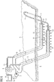
- FIG. 1 shows, schematically illustrated, an apparatus for in situ recovery of a hydrocarbonaceous substance from an underground reservoir 6 as a reservoir while reducing its viscosity, wherein cooling of inductors 10 is provided.
- a device for recovering bitumen from an oil sands deposit.
- the deposit 6 may be, in particular, an oil sands deposit or an oil shale occurrence from which bitumen or other heavy oils may be recovered.
- a tube 9 for introducing steam is shown, which is arranged substantially between parallel sections of an inductor 10 within the reservoir 6 and which is fed via a steam generator 8.
- a steam generator 8 By means distributed over the length of the tube arranged nozzles - not shown - the steam is pressed into the reservoir 6.
- the apparatus for in situ recovery of a hydrocarbonaceous substance further comprises an inductor 10 extending into wells within the reservoir 6.
- the inductor 10 or portions thereof are considered to be the inventive conductor. It is formed a closed loop conductor, which consists of the two horizontally extending in the reservoir 6 back and forth conductors of the inductor 10, and of conductor pieces 11 which act little or little as a heater and run above ground or from the earth's surface 5 into the deposit 6 to ensure the power connection for the inductor 10.
- both loop ends of the conductor loop are arranged above ground.
- the loop is simply closed by - see ladder 11 in the figure.
- an electrical supply 1 including all necessary electrical equipment such as inverter and generator, through which the necessary power and the necessary voltage is applied to the conductor loop, so that the inductors 10 as a conductor serve for an electric / electromagnetic heater for heat generation in the storage site 6.
- the inductors 10 are effective against at least parts of the deposit 6 as an inductive electric heater. Due to the conductivity of at least parts of the deposit 6, this can be heated by the largely concentric around the two as possible parallel sections of the inductor 10.
- the conductor loop can be greatly reduced in areas where they run outside the actual deposit 6 - as the conductor pieces 11 - by means of suitable guidance in their heating capacity. In this way, the heating power can be introduced in defined areas of the deposit 6.
- the inductor 10 may be rod-shaped metallic conductors or twisted metallic cables made of a metal that is in particular highly conductive, which are formed as a resonant circuit.
- a cooling circuit is provided to cool the inductor 10.
- the cooling circuit comprises a liquid guide 12 which according to the figure almost completely surrounds the conductor loop along its length. Much is merely a sheath of the inductor 10. A sheath outside the deposit 6 is not necessary, but may be advantageous, since thereby the laying of the liquid guide 12 can be done together with the conductor loop, thus allowing a simplified installation.
- the sections of the cooling circuit which are not explicitly intended for cooling, are marked as liquid inlets / outlets 13.
- the liquid circuit On the left side of the liquid circuit is closed only in a simple manner to a ring, so that by a first Liquid guide 12 along a first portion of the inductor 10 passed liquid through a second liquid guide 12 along a second portion of the inductor 10 is returned.
- the components to provide the liquid On the right side of the figure are above ground, the components to provide the liquid. These are a reservoir 3, in which the liquid 14 is located for cooling.
- a pump 2 is provided to pump the liquid 14 into the cooling circuit and to ensure a flow rate.
- a recooler 4 is provided, through which the heated cooling liquid can be cooled down.
- the liquid guide 12 is formed in the figure as a coaxial sheathing to the inductor 10, so that the inductor 10 - or a sheath of the inductor 10 - is surrounded as completely as possible during operation of a cooling liquid.
- the device may be operated such that when current is applied to the inductor 10, which heats the vicinity of the inductor 10 in the reservoir 6, a cooling fluid is always conducted through the fluid guide 12 along the inductor 10.
- the inductor 10 heats the bottom in the vicinity of the inductor 10, whereby the heated floor itself becomes the thermal radiator.
- the inductor 10 is to be protected from elevated temperatures. This is done by the cooling liquid in the liquid guide 12 in the form of the described external cooling of the inductor 10, whereby on the one hand the inductor 10 thermally insulated and on the other hand the temperature absorbed by the inductor 10 is dissipated again, so that the inductor 10 does not heat or at least only slightly or to a lesser extent.
- the liquid guide 12 may be additionally sheathed by a thermal insulator.
- the inductor 10 is integrated with the liquid guide 12 and may be laid as a unit. Various configurations of such combined conductors and cooling are explained below.
- FIG. 2 a section of an inductor 10 with a surrounding cooling is schematically illustrated in a perspective view.
- An inductor 10 centered in a tubular jacket 15 of the liquid guide 12 is surrounded by a liquid guide 12.
- the positioning of the inductor 10 may for example be determined solely by the flowing liquid in the liquid guide 12. On a centering is according to FIG. 2 waived.
- the inductor 10 is accordingly largely freely movable in the liquid guide 12 and could, for example, also come to rest on the liquid casing due to the weight force.
- For a specific positioning or fixation in the Liquid guide 12, however, are presented below various embodiments.
- the diameter of the inductor 10 may preferably be 30 to 100 mm.
- the annular gap width of the inductor 10 will preferably be 5 mm to 50 mm and the mass flow of the cooling medium within the liquid guide 12 preferably 5 to 100 1 / min.
- cross sections of cooled conductors are schematically illustrated.
- the cross section is taken along a cut surface, as in FIG. 1 is indicated by AA.
- a support of the inductor 10 by, for example, star-shaped spacers - webs 16 -, wherein preferably 2 to 5 spacers are used.
- the webs 16 are preferably attached to the inner wall of the shell 15 and are connected in the center via stabilizers 17 or attached directly to the outer shell of the inductor 10.
- the inductor 10 is located coaxially in the center of the casing 15 of the liquid guide 12 and is either laid as a unit with the casing 15 and the webs 16 or is subsequently retracted.
- the liquid guide 12 results from the cavities within the casing 15th
- the width of the webs 16 may, for example, in the range 5-30 mm, so that the pressure losses of the cooling medium in the liquid guide 12 are not too large.
- FIG. 4 To FIG. 4 are in the annular space - ie within an outer shell 20 - around the inductor 10 a plurality of tubes or tubes 12A, 12B, ..., 12F provided as a liquid guide 12.
- a thermal insulator 18 between the tubes / tubes and the outer shell 20 may additionally be used. In this sense is also to be understood, if these spaces remain empty, ie air or a specific gas or a vacuum serve as thermal insulation.
- the thickness of a thermal insulation layer can be selected between 3 and 50 mm.
- the cooling medium is passed through capillaries 19 as a liquid guide 12.
- it may also be porous material.
- These variants have the particular advantage that the liquid flow within the liquid guide 12 can be better controlled and that the position of the inductor 10 in relation to the liquid guide 12 can be specified exactly. This can be advantageous, since the induced field does not have the same strength on all sides of the inductor 10, depending on the orientation of the two inductors 10 relative to each other.
- FIG. 6 Completeness is according to FIG. 6 a further variant of the liquid cooling shown, in which a central, the cooling medium leading hose or tube is surrounded as a liquid guide 12 of the sub-conductors 10A, 10B, ..., 10F.
- the sub-conductors 10A, 10B,..., 10F together represent the inductor 10.
- the hose or pipe diameter of the liquid guide 12 can be between 10 and 100 mm and the mass flow of the cooling medium can be between 5 and 100 l / min.
- the inductor 10 may be, for example, 10 to 2000 Partial conductors consist whose total cross-sectional area is typically from 10 to 2000 mm 2 .
- FIG. 7 schematically illustrates a portion of an inductor 10 with a surrounding cooling in a perspective view, wherein a liquid guide 12 is formed perforated so that liquid can escape, the liquid can actually escape in liquid form or possibly as a gas, eg Steam.
- a liquid guide 12 is formed perforated so that liquid can escape, the liquid can actually escape in liquid form or possibly as a gas, eg Steam.
- Analogous to FIG. 2 is a centered in a tubular sheath 15 arranged inductor 10 is surrounded by a liquid guide 12.
- a perforation 12 consisting of a plurality of holes and passages through which the liquid transported from the inside to the outside can penetrate.
- the size, position and frequency of the holes is to be adapted to the desired conditions and by the representation in FIG. 7 not to be interpreted as limiting, in particular so that, for example, 30 to 300 l / min can escape over the entire length of the liquid guide 12.
- the holes of the perforation 21 can be arranged symmetrically on the entire circumference of the sheath 15. However, it could also be advantageous to provide an uneven distribution. Also over the length of the liquid guide 12, the distribution and / or the design of the holes may change, especially as the pressure within the Can change liquid guide 12 due to the exiting liquid.
- An escaping liquid in the reservoir 6 in the vicinity of the inductor 10 has an advantage in that thereby in this way an electrolyte can be injected into the reservoir, which on the one hand can increase the electrical conductivity in the reservoir 6 and on the other hand increased pressure within the deposit 6 results. Both effects show that the production rate and / or the conveying speed of the hydrocarbonaceous substance to be pumped can be increased. Further explanations are given by hand FIG. 8 ,
- FIG. 8 corresponds fundamentally to the structure of FIG. 1 , There is a conductor loop which is operated by an electrical supply 1. Sections acting as an electrode are highlighted as inductor 10. These are the horizontal and parallel in the deposit 6 extending sections.
- This liquid 14 is introduced by means of the pump 2 into a liquid system which consists of the liquid inlets 13 and of the liquid guide 12.
- the liquid guide 12 is again intended to denote the sections extending horizontally and parallel in the deposit 6.
- the liquid discharges 13 comprise the clever / pipe system above the earth's surface 5 or the connection to the horizontally running liquid guide 12.
- the feeding takes place in the present example, in contrast to FIG. 1 from the left on the drawing plane, but also a feeder from the right, as in FIG. 1 would be possible.
- essential difference to FIG. 1 is, however, that in the horizontal subterranean section, the liquid guide 12 has a perforation 21, through which an exiting liquid 22 is indicated by arrows.
- the liquid guide 12 already ends underground.
- a closure 23 of the liquid guide 12 is provided, wherein this conclusion may also have a perforation.
- the liquid guide 12 is returned to the surface for a remaining liquid residue.
- the liquid guide 12 can be returned to the surface, however, results due to the pressure conditions that no liquid reaches the earth's surface 5. The liquid guide 12 would thus be liquidless in the last section.
- liquid is introduced into the cooling system by means of a pump 2 or similar device.
- the pressure remains essentially unchanged until the liquid guide 12, since no liquid outlet is provided until the beginning of the liquid guide 12. If the liquid supplied now reaches the section with the liquid guide 12 according to the invention, part of the liquid is introduced into the reservoir 6 via the perforation 21. Another part of the liquid continues to flow along the liquid guide 12, wherein liquid is always discharged through the perforation 21. This results in an outflow of liquid through the exiting liquid 22. The loss of liquid is replaced by the pump 2 by flowing liquid.
- the liquid flows along the inductor 10 and can dissipate heat.
- liquid flows into the reservoir 6, in the vicinity of the inductors 10, whereby the pressure in the reservoir 6 can be increased or a decreasing pressure due to the promotion of the hydrocarbonaceous substance can be compensated, and the electrical conductivity in the reservoir 6 can be increased, in particular in the vicinity of the inductors 10, which in turn increases the effectiveness of the inductors 10.
- the effects mentioned mutually influence each other, because the flow of the heated liquid into the environment of the inductor 10 causes cool liquid to flow along the inductor 10 within the liquid guide 12, thereby maintaining the cooling or thermally insulating effect.
- the closure 23, the dimensions of the liquid guide 12, the configuration of the perforation 21 and the pressure applied to the liquid via the pump 2 should preferably be adapted to each other - especially taking into account the existing rock formations and the depth of the deposit - that substantially over the entire length of the horizontally extending inductor 10, the effects mentioned occur and / or even liquid 22 exits into the reservoir 6.
- the pressure is dependent on the depth of the deposit, i. from the distance of horizontally laid inductors 10 to the earth's surface 5, depending.
- the pressure should be higher than the hydrostatic pressure of the corresponding water column and is for example in the range between 10000 hPa (10 bar) to 50,000 hPa (50 bar).
- Pressure relief in the reservoir 6 is made by opening the production pipe (not shown) at a time when the pressure on an overburden above the reservoir 6 becomes too high.
- the function of the exiting liquid 22 is thus both increasing or maintaining the pressure in the reservoir 6, as well as displacement - flushing - of the substance to be conveyed, whereby avoiding a negative pressure in the reservoir 6 is achieved.
- an electrolyte As a liquid, in particular an electrolyte, for.
- water or aqueous solutions may be provided, for example, mixed with other ingredients.
- Suitable electrolytes, displacers or solvents are, in particular, organic or inorganic liquids or gases modified in the state of matter, or combinations thereof., In particular water - preferably produced and separated from heavy oil -, salt water, weak acids, weak bases, other solvents such as methane, Propane, butane, CO2 or mixtures.
- FIGS. 2 to 5 presented cross sections are also applicable to the liquid guide 12 with leaking liquid 22.
- the inductor 10 can be located in a perforated injector tube or tube, in which centering of the inductor 10 is dispensed with.
- the diameter of the inductor 10 will preferably be 30 to 100 mm.
- the annular gap width will preferably be 5 mm to 50 mm and the mass flow of the cooling medium preferably 30 to 300 l / min.
- the inductor 10 is located in a perforated Injektorrohr or hose, wherein a support of the inductor 10 is effected by star-shaped spacers.
- the diameter of the inductor 10 will preferably be 30 to 100 mm.
- the annular gap width will preferably be 5 mm to 50 mm and the mass flow of the cooling medium preferably 30 to 300 l / min.
- one or more perforated injector tubes or tubes are attached to the inductor 10.
- the direct contact of the inductor 10 to the reservoir is provided.
- the lack of contact may even be advantageous as the heat transfer from the surrounding hot reservoir back to the inductor 10 is reduced.
- the diameter of the inductor 10 will preferably be 30 to 100 mm.
- the diameter of the adjacent pipes preferably amounts to 5 mm to 50 mm and the mass flow of the cooling medium preferably 30 to 300 l / min.
- the device so that only portions of the inductor 10 are in an injector tube or hose. Furthermore, the exit holes of the perforation 21 may be distributed unevenly or even be present sections in which no perforation 21 is present.
- FIG. 9 is a sectional view of a deposit 6 shown schematically, wherein the deposit 6 is disposed below the surface of the earth 5 and has a region 7 with oil deposits. It is provided as in the previous embodiments, a conductor loop, wherein in FIG. 9 only an inductor 10 of the conductor loop is shown.
- the inductor 10 is at least partially encased by a liquid guide 12.
- the conductor loop is operated by an electric power supply 1 as in the above embodiments.
- a production pipe 39 for transporting away the substance to be conveyed in the soil available.
- a production stream 30 in the form of a liquid-solid-gas mixture - ie a phase mixture - can be transported to the surface of the earth 5 for processing.
- the substance to be delivered is separated from the liquid-solid-gas mixture by means of an oil / gas separator 31.
- a resulting separated oil 32 is indicated in the figure as an arrow, as well as an alternatively or additionally resulting separated gas 33.
- a residual liquid 34 - Produced Water - of the separated production stream 30 remains, which is further processed in the following, so that later can be injected back into the reservoir 6 in liquid form.
- the residual liquid 34 is supplied to a desanding device 35, in which sands and other solids are separated off. After this treatment step, a sanded residual liquid 36 remains.
- the remaining residual liquid 36 that has been disposed of already has a consistency that is possible for re-injecting in liquid form. This is because a pipe used for re-injecting can be operated long-term without suds or clogging by the deposited residual liquid 35.
- the desanded residual liquid 36 is fed to a desalination device 37, by means of which the salt content of the disposed residual liquid 36 is reduced. This can be achieved by adding specific chemicals. Desalting means 37 ideally achieve a salinity in the resulting conditioned liquid 38 which corresponds to a natural salinity within the deposit 6.
- the thus prepared liquid 38 can now in the cooling circuit according to FIG. 1 or the liquid injection according to FIG. 8 be supplied. Another alternative variant will be described below FIG. 9 explained.
- FIG. 9 the treated liquid 38 is fed to a pump 2 and pressed under pressure into the liquid inlet 13, which later merges into the liquid guide 12.
- the inductor 10 is again guided within the liquid inlet 13 and the liquid guide 12.
- FIG. 9 an embodiment is shown, in which the inductor 10 is fixed over sections of existing webs 16 within the liquid guide or - introduction.
- the conditioned liquid 38 is thus introduced along the inductor 10 within the liquid inlet 13 and the liquid guide 12 within a hose or tube to a depth of the reservoir 6.
- the liquid guide 12 is slotted, so that the liquid 38 penetrates via slots 40 from the liquid guide 12 into the substrate.
- the liquid which penetrates there can vaporize in the course of time due to the heating effect of the inductor 10.
- the length of the liquid guide 12 is limited and ends, while the inductor 10 continues to extend horizontally.
- the length of the slotted liquid guide 12, the frequency and size of the slots 40 and the amount of injected liquid 38 should be coordinated.
- liquid guide 12 as in FIG. 8 along the substantially entire active length of the inductor 10 to ensure a larger area distribution of the liquid to be injected.
- heated water can be used to avoid unwanted cooling of the reservoir and thus pressure drop or viscosity increase in the reservoir.
- the device with respect to temperature and thus pressure control in the reservoir is easy to control.
Description
Vorrichtung und Verfahren zur Gewinnung, insbesondere In-Situ-Gewinnung, einer kohlenstoffhaltigen Substanz aus einer unterirdischen LagerstätteApparatus and method for recovering, in particular recovering, a carbonaceous substance from a subterranean deposit
Die Erfindung betrifft eine Anlage zur In-Situ-Gewinnung einer kohlenstoffhaltigen Substanz aus einer unterirdischen Lagerstätte unter Herabsetzung von deren Viskosität. Eine solche Vorrichtung dient insbesondere zur Förderung von Bitumen oder Schwerstöl aus einem Reservoir unter einem Deckgebirge, wie es bei Ölschiefer und/oder Ölsandvorkommen beispielsweise in Kanada gegeben ist.The invention relates to an installation for the in situ recovery of a carbonaceous substance from an underground deposit with reduction of its viscosity. Such a device is used in particular for the production of bitumen or heavy oil from a reservoir under an overburden, as is the case with oil shale and / or oil sand deposits, for example in Canada.
Zur Förderung von Schwerstölen oder Bitumen aus den bekannten Ölsand- oder Ölschiefervorkommen muss deren Fließfähigkeit erheblich erhöht werden. Dies kann durch Temperaturerhöhung des Vorkommens (Reservoirs) erreicht werden. Die Erhöhung der Fließfähigkeit kann zum einen durch Einbringen von Lösungs- bzw. Verdünnungsmitteln und/oder zum anderen durch Aufheizen bzw. Aufschmelzen des Schwerstöl oder Bitumens erfolgen, wozu mittels Rohrsystemen, welche durch Bohrungen eingebracht werden, eine Beheizung erfolgt.For the promotion of heavy oils or bitumen from the known oil sand or oil shale deposits their flowability must be significantly increased. This can be achieved by increasing the temperature of the reservoir. The increase in fluidity can be done firstly by introducing solvents or diluents and / or on the other by heating or melting of the heavy oil or bitumen, for which by means of pipe systems, which are introduced through holes, heating takes place.
Das am weitesten verbreitete und angewendete In-Situ-Verfahren zur Förderung von Bitumen oder Schwerstöl ist das SAGD(Steam Assisted Gravity Drainage)-Verfahren. Dabei wird Wasserdampf, dem Lösungsmittel zugesetzt sein können, unter hohem Druck durch ein innerhalb des Flözes horizontal verlaufendes Rohr eingepresst. Das aufgeheizte, geschmolzene und vom Sand oder Gestein abgelöste Bitumen oder Schwerstöl sickert zu einem zweiten etwa 5 m tiefer gelegenem Rohr, durch das die Förderung des verflüssigten Bitumens oder Schwerstöl erfolgt, wobei der Abstand von Injektor und Produktionsrohr abhängig von Reservoirgeometrie ist.The most widely used and applied in-situ process for the extraction of bitumen or heavy oil is the SAGD (S team A ssisted G ravity D rainage) process. In this case, water vapor, which may be added to the solvent, is pressed under high pressure through a tube extending horizontally within the seam. The heated, molten bitumen or heavy oil removed from the sand or rock seeps to a second pipe located about 5 m lower, through which the liquefied bitumen or heavy oil is conveyed, the distance between injector and production pipe being dependent on reservoir geometry.
Der Wasserdampf hat dabei mehrere Aufgaben gleichzeitig zu erfüllen, nämlich die Einbringung der Heizenergie zur Verflüssigung, das Ablösen vom Sand sowie den Druckaufbau im Reservoir, um einerseits das Reservoir geomechanisch für Bitumentransport durchlässig zu machen (Permeabilität) und andererseits die Förderung des Bitumens ohne zusätzliche Pumpen zu ermöglichen.The steam has to fulfill several tasks at the same time, namely the introduction of heating energy for liquefaction, the detachment of the sand and the pressure build-up in the reservoir, on the one hand to make the reservoir geomechanically permeable for bitumen transport (permeability) and on the other hand, the promotion of bitumen without additional pumps to enable.
Das SAGD-Verfahren startet, indem für beispielsweise drei Monate durch beide Rohre Dampf eingebracht wird, um zunächst möglichst schnell das Bitumen im Raum zwischen den Rohren zu verflüssigen. Danach erfolgt die Dampfeinbringung nur noch durch das obere Rohr und die Förderung durch das untere Rohr kann beginnen.The SAGD process starts by introducing steam through both pipes, for example for three months, in order first to liquefy the bitumen in the space between the pipes as quickly as possible. Thereafter, the steam is introduced only through the upper tube and the promotion through the lower tube can begin.
Die Dampferzeugung erfolgt üblicherweise an der Tagesoberfläche. Aus der Schrift zur Patentanmeldung
In der deutschen Patentanmeldung
Bei den älteren, deutschen Patentanmeldungen
Bei den vorbeschriebenen Einrichtungen muss immer die elektrische Energie über einen elektrischen Hinleiter und einen elektrischen Rückleiter geführt werden. Dazu ist ein nicht unerheblicher Aufwand notwendig.In the above-described devices, the electrical energy must always be passed through an electrical forward conductor and an electrical return conductor. This requires a considerable effort.
Bei den genannten älteren Patentanmeldungen werden einzelne Induktorpaare aus Hin- und Rückleiter oder Gruppen von Induktorpaaren in verschiedenen geometrischen Konfigurationen bestromt, um das Reservoir induktiv zu erhitzen. Dabei wird innerhalb des Reservoirs von einem konstanten Abstand der Induktoren ausgegangen, was bei homogener elektrischer Leitfähigkeitsverteilung zu einer konstanten Heizleistung entlang der Induktoren führt. Beschrieben sind die räumlich eng beieinander geführten Hin- und Rückleiter in den Abschnitten, in denen das Deckgebirge durchstoßen wird, um dort die Verluste zu minimieren.In the said earlier patent applications, individual inductor pairs of forward and return conductors or groups of inductor pairs in different geometric configurations are energized to inductively heat the reservoir. In this case, a constant distance of the inductors is assumed within the reservoir, resulting in a homogeneous electrical conductivity distribution to a constant heat output along the inductors. Described are the spatially close together outgoing and return conductors in the sections in which the overburden is pierced in order to minimize losses there.
Eine Variation der Heizleistung entlang der Induktoren kann, wie in den älteren Anmeldungen beschrieben, speziell durch abschnittsweise Injektion von Elektrolyten erfolgen, womit die Impedanz verändert wird. Dies setzt entsprechend Elektrolytinjektionsvorrichtungen voraus, deren Installation aufwendig oder kostspielig sein kann.A variation of the heating power along the inductors can, as described in the earlier applications, be carried out specifically by sectionwise injection of electrolytes, whereby the impedance is changed. This requires corresponding electrolyte injection devices whose installation can be complicated or costly.
Davon ausgehend ist es Aufgabe der Erfindung, die vorbeschriebene Einrichtung für eine induktive Beheizung weiter zu optimierten.On this basis, it is an object of the invention to further optimize the above-described device for inductive heating.
Die Aufgabe wird erfindungsgemäß durch die Merkmale der unabhängigen Patentansprüche gelöst. Vorteilhafte Weiterbildungen und Ausgestaltungen der Erfindung sind in den Unteransprüchen angegeben.The object is achieved by the features of the independent claims. Advantageous developments and refinements of the invention are specified in the subclaims.
Erfindungsgemäß ist eine Vorrichtung zur Förderung von einer kohlenwasserstoffhaltigen Substanz, insbesondere Bitumen oder Schwerstöl, aus einem Reservoir vorgesehen, wobei das Reservoir mit Wärmeenergie zur Verringerung der Viskosität der Substanz beaufschlagbar ist, wozu wenigstens eine Leiterschleife zur induktiven Bestromung des Reservoirs als elektrische/elektromagnetische Heizung des Reservoirs vorgesehen ist, wobei ein Leiter - ein Induktor - der Leiterschleife in zumindest einem Abschnitt von einer Flüssigkeitsführung umgeben ist und die Flüssigkeitsführung perforiert ist, so dass bei Zuführung einer Flüssigkeit die Flüssigkeit über eine Perforation aus der Flüssigkeitsführung in das Reservoir eindringt.According to the invention, a device for conveying a hydrocarbon-containing substance, in particular bitumen or heavy oil, is provided from a reservoir, wherein the Reservoir with heat energy to reduce the viscosity of the substance is acted on, including at least one conductor loop for inductive energization of the reservoir is provided as electrical / electromagnetic heating of the reservoir, wherein a conductor - an inductor - the conductor loop is surrounded in at least a portion of a liquid guide and the liquid guide is perforated, so that when a liquid is supplied, the liquid penetrates via a perforation from the liquid guide into the reservoir.
Erfindungsgemäß handelt es sich also um eine "in-situ"-Förderung, also die Förderung der kohlenwasserstoffhaltigen Substanz direkt aus dem Reservoir, in dem diese Substanz angereichert ist, ohne das Reservoir im Tagebau abzubauen. Als Reservoir versteht man vorzugsweise eine Ölsand-Lagerstätte, die unterirdisch zu finden ist.According to the invention, it is therefore an "in situ" promotion, ie the promotion of the hydrocarbonaceous substance directly from the reservoir in which this substance is enriched without degrading the reservoir in the open pit. As a reservoir is preferably understood an oil sands deposit that can be found underground.
Erfindungsgemäß ist keine Einbringung von Dampf über die Flüssigkeitsführung vorgesehen. Jedoch kann eine Kombination zusätzlich mit dem SAGD-Verfahren vorteilhaft sein, beispielsweise das Kühlen des Induktors gemäß der erfindungsgemäßen Vorrichtung und ein Einbringen von Dampf über ein weiteres Rohr oder einen weiteren Schlauch.According to the invention, no introduction of steam via the liquid guide is provided. However, a combination may additionally be advantageous with the SAGD method, for example cooling the inductor according to the device according to the invention and introducing steam via a further tube or a further tube.
Unter Abschnitt des Leiters ist ein Teilstück des Leiters zu verstehen. Wird angenommen, dass es sich um den Leiter im wesentlichen um ein verdrilltes Kabel handelt, dass von einer röhrenförmigen Hülle ummantelt ist, so ist als Abschnitt des Leiters ein Teilstück entlang der Erstreckung des Kabels und der Hülle zu verstehen.The section of the conductor means a section of the conductor. Assuming that the conductor is essentially a twisted cable encased in a tubular sheath, the portion of the conductor means a section along the length of the cable and sheath.
Als Leiter wird insbesondere ein serieller Resonanzkreis oder ein Teil davon verstanden, welcher in einem kabelartigen Aufbau mit äußerer Isolierung gebracht wird. Dies ist erfindungsgemäß von einer Flüssigkeitsführung umgeben.As a conductor, in particular a serial resonant circuit or a part thereof is understood, which is brought in a cable-like structure with external insulation. This is according to the invention surrounded by a liquid guide.
Die Flüssigkeitsführung ist ein ausgedehnter hohler Körper - beispielsweise ein Rohr oder ein Schlauch - zu verstehen, durch den Flüssigkeit transportiert werden kann.The liquid guide is an extended hollow body - for example, a tube or a tube - to understand, can be transported through the liquid.
Durch das Vorsehen einer Flüssigkeitsführung kann eine Flüssigkeit entlang des Leiters und in das Reservoir geleitet werden. Je nach Ausgestaltung der Flüssigkeitsführung können sich dadurch folgende Vorteile ergeben:
- i) Erhöhung der elektrischen Leitfähigkeit im Reservoir mittels Einleiten von Flüssigkeit in das Reservoir.
Ein Problem beim elektromagnetischen Heizen mittels Induktion mancher Lagerstätten ist nämlich, dass die elektrische Leitfähigkeit in der Lagerstätte verhältnismäßig niedrig sein kann, und damit die resultierende, in die Lagerstätte eingebrachte, thermische Leistung möglicherweise nicht ausreichend ist, oder sogar hohe Energieverluste in der unmittelbarer Umgebung der Lagerstätte aufgrund der großen Eindringtiefen der magnetischen Felder entstehen. Somit kann erfindungsgemäß auf eine Erhöhung der elektrischen Eingangsleistung verzichtet werden, wodurch die Rentabilität und die Umweltfreundlichkeit des Prozesses maßgeblich beeinträchtigt würde. - ii) Erhöhte Verdrängung der kohlenwasserstoffhaltigen Substanz, z.B. des Öls, durch das Einleiten von Flüssigkeit in das Reservoir.
Ein weiteres Problem beim elektromagnetischen induktiven Heizen ist nämlich die mangelnde oder unzureichende Verdrängung des Öls aus der Lagerstätte während der Förderung, was die Förderrate beeinträchtigen oder sogar die Förderung zum Stillstand bringen kann. Die Ölverdrängung beim SAGD-Verfahren nach dem Stand der Technik erfolgt durch die Ausdehnung der Wasserdampfkammer in der Lagerstätte. Beim erfindungsgemäß vorgesehenen elektromagnetischen induktiven Heizen ohne zusätzliche Dampfeinbringung gibt es nicht zwangsläufig eine Wasserdampfkammer, so dass eine Ölverdrängung aufgrund einer Wasserdampfkammer nicht erfolgen kann. Dies wäre nur bei Einbringung sehr großer elektrischer Leistung über die Induktoren möglich, was aber vorzugsweise vermieden werden soll. - iii) Kühlung des Leiters, indem die Flüssigkeit direkt oder in der Nähe des Leiters entlanggeleitet wird, um einem Aufwärmen des Leiters durch die erhitzte Umgebung des Leiter entgegenzuwirken oder auch zur Aufnahme bereits im Leiter angefallene Erwärmung. Darüber hinaus kann es vorteilhaft sein dass auch die Umgebung des Leiters gekühlt werden kann, damit kein siedenes Wasser im Reservoir in direkte Berührung mit dem Leiter oder dessen Ummantelung kommt, wobei jedoch anzumerken ist, dass prinzipiell ein Sieden von Wasser im Reservoir vorteilhaft ist, um beispielsweise eine Verdrängung von Öl zu erreichen.
- i) increasing the electrical conductivity in the reservoir by introducing liquid into the reservoir.
Namely, a problem with electromagnetic heating by induction of some deposits is that the electrical conductivity in the deposit may be relatively low, and that the resulting thermal power introduced into the deposit may not be sufficient, or even high energy losses in the immediate vicinity Deposit arise due to the large penetration depths of the magnetic fields. Thus, according to the invention can be dispensed with an increase in the electrical input power, which would significantly affect the profitability and environmental friendliness of the process. - ii) Increased displacement of the hydrocarbonaceous substance, eg of the oil, by the introduction of liquid into the reservoir.
Another problem with electromagnetic inductive heating is the lack of or inadequate displacement of the oil from the reservoir during production, which may affect the production rate or even stop the production. The oil displacement in the SAGD method according to the prior art is carried out by the expansion of the steam chamber in the deposit. When inventively provided electromagnetic inductive heating without additional steam injection there is not necessarily a water vapor chamber, so that an oil displacement due to a steam chamber can not be done. This would only be possible with the introduction of very large electrical power through the inductors, but this should preferably be avoided. - iii) cooling the conductor by passing the liquid directly or in the vicinity of the conductor to counteract heating of the conductor by the heated environment of the conductor or also to absorb heating already incurred in the conductor. In addition, it may be advantageous that the environment of the conductor can be cooled so that no boiling water in the reservoir comes into direct contact with the conductor or its sheath, it being noted, however, that in principle a boiling of water in the reservoir is advantageous to For example, to achieve a displacement of oil.
Durch das Kühlen des Leiters kann die elektrische Leitfähigkeit in der unmittelbaren Umgebung um den Leiter reduziert werden und somit die geometriebedingt hohe Heizleistungsdichte direkt am Leiter zu reduzieren. Man kann somit eine homogenere Heizleistungsdichte im Reservoir erreichen.By cooling the conductor, the electrical conductivity in the immediate vicinity of the conductor can be reduced, thus reducing the geometry-related high heating power density directly at the conductor. It is thus possible to achieve a more homogeneous heating power density in the reservoir.
Die Kühlung ist insbesondere bei größeren Lagerstättetiefen - etwa größer als 130 m - vorteilhaft, weil es ansonsten zur Überhitzung des Induktors, beispielsweise bei Temperaturen von ca. 200°C oder mehr, kommen könnte. Insbesondere eine Kunststoffisolation des Induktors könnte einer solchen hohen Temperatur dauerhaft nicht standhalten. Zu beachten ist hierbei, dass die Siedetemperatur von Wasser im Reservoir bei einer Tiefe von 130 m oder darüber hinaus bei ca. 200°C liegen kann.The cooling is particularly advantageous for larger storage depths - about greater than 130 m - advantageous because otherwise it could lead to overheating of the inductor, for example, at temperatures of about 200 ° C or more. In particular, a plastic insulation of the inductor could not permanently withstand such a high temperature. It should be noted here that the boiling point of water in the reservoir at a depth of 130 m or more can be around 200 ° C.
Die Wärme des Leiters umfasst einerseits Wärme aufgrund ohmscher Verluste im Leiter, jedoch wesentlicher kann die Wärme aus dem Reservoir sein, die der Leiter ohne entsprechende Kühlung aus der Umgebung aus dem Reservoir aufnehmen würde.On the one hand, the heat of the conductor comprises heat due to ohmic losses in the conductor, but more importantly, the heat from the reservoir, which the conductor would receive from the reservoir without corresponding cooling from the environment, can be more significant.
Insbesondere über den Kontakt der Flüssigkeit mit einer Rohrwandung, welche wiederum mit dem Reservoir in Kontakt steht, wird vorteilhafterweise die Rohrwandungswärme abgeführt.In particular, via the contact of the liquid with a tube wall, which in turn with the reservoir in contact is, advantageously the heat pipe wall heat dissipated.
Weitere joulsche Verluste im Leiter können über die äußere, mit der Flüssigkeit in Kontakt stehende Isolierung des Leiters an die Flüssigkeit abgeführt werden, wobei die Flüssigkeit in einem äußeren Rohr geführt wird.Further negative losses in the conductor can be dissipated to the liquid via the outer, liquid-contacting insulation of the conductor, the liquid being guided in an outer tube.
Im Folgenden werden zuerst die Merkmale für eine Kühlung der des Leiters erläutert. Hierbei basiert der erfinderische Gedanke im wesentlichen auf eine Flüssigkeitsführung mit geschlossenem Flüssigkeitskreislauf, bei dem kühle Flüssigkeit entlang des Leiters innerhalb der Flüssigkeitsführung fließt, im Reservoir aufgeheizt wird und wieder aus dem Reservoir hinausgeleitet wird. Darauf aufbauend wird dann der zusätzliche erfinderische Gedanke erläutert, bei dem zusätzlich oder alternativ zur Kühlung, die Flüssigkeit über die Flüssigkeitsführung ins Reservoir eingespeist wird und dort im Erdreich verteilt wird, um weitere Effekte - beispielsweise die Verbesserung der Leitfähigkeit im Reservoir - zu erzielen.The features for cooling the conductor will first be explained below. Here, the inventive idea is based essentially on a fluid guide with a closed fluid circuit in which cool liquid flows along the conductor within the fluid guide, is heated in the reservoir and is led out of the reservoir again. Based on this, the additional inventive concept is explained, in which additionally or alternatively to the cooling, the liquid is fed via the liquid guide into the reservoir and is distributed there in the ground, in order to achieve further effects - for example the improvement of the conductivity in the reservoir.
In einer bevorzugten Ausgestaltung können die Flüssigkeitsführung und der Leiter derart zueinander angeordnet sein, dass eine Flüssigkeit in der Flüssigkeitsführung eine Kühlung des Leiters bewirkt. Dabei ist es irrelevant, ob es sich um eigene Abwärme des Leiters handelt oder ob es Wärme ist, die von Außen, vom durch den stromführenden Leiter erhitzten Reservoir, auf den Leiter wirkt. Der kühlende Effekt kann durch Bewegung der Flüssigkeit, insbesondere entlang des Leiters und unter Umwälzung oder Austausch der Flüssigkeit, verstärkt werden, da dadurch warme Flüssigkeit weggeleitet wird und kühle Flüssigkeit nachfließen kann.In a preferred embodiment, the liquid guide and the conductor may be arranged to each other such that a liquid in the liquid guide causes cooling of the conductor. It is irrelevant whether it is the conductor's own waste heat or whether it is heat acting on the conductor from the outside, from the reservoir heated by the current-carrying conductor. The cooling effect can be enhanced by movement of the liquid, in particular along the conductor and with circulation or exchange of the liquid, since warm liquid is thereby conducted away and cool liquid can flow.
Vollständigkeitshalber sei erwähnt, dass in einer weiteren vorteilhaften Ausgestaltung die Flüssigkeitsführung Teil eines im wesentlichen geschlossenen Flüssigkeitskreislaufs sein kann, bei dem ein Mittel zum Wärmetauschen - insbesondere an der Oberfläche und nicht innerhalb des Reservoirs - vorgesehen ist, um eine innerhalb der Flüssigkeitsführung erhitzte Flüssigkeit wieder abzukühlen.For completeness, it should be mentioned that in a further advantageous embodiment, the liquid guide may be part of a substantially closed liquid circuit, in which a means for heat exchange - in particular on the surface and not within the reservoir - is provided to cool a liquid heated within the liquid guide again ,
Mittels einer weiteren vorteilhaften Ausgestaltung kann die Rückkühlung der Flüssigkeit durch Rohre erfolgen, die durch kältere Bereich des Reservoirs führen, d.h. die Flüssigkeit wird nicht an die Oberfläche gebracht, sondern zirkuliert nur in der Tiefe. In diesem Fall ist vorzugsweise eine Pumpe in der Tiefe zu installieren. Vorteilhaft ist dabei, dass die elektrisch eingebrachte Heizleistung dem Reservoir nicht entzogen wird, sondern nur anders verteilt wird.By means of a further advantageous embodiment, the re-cooling of the liquid can be effected by tubes which pass through colder region of the reservoir, i. The liquid is not brought to the surface, but circulates only in the depth. In this case, it is preferable to install a pump at depth. It is advantageous that the electrically introduced heating power is not withdrawn from the reservoir, but only distributed differently.
Vorteilhafterweise kann die Flüssigkeitsführung als Schlauch und/oder Rohr ausgebildet sein, wobei der Leiter innerhalb des Schlauchs bzw. des Rohrs angeordnet ist, insbesondere so dass bei Zuführung einer Flüssigkeit der Leiter von der Flüssigkeit umspült wird. Somit kann eine optimale Übertragung von Wärme vom Leiter auf die Flüssigkeit gewährleistet werden.Advantageously, the liquid guide may be formed as a tube and / or tube, wherein the conductor is disposed within the tube or the tube, in particular so that when supplied with a liquid, the conductor is surrounded by the liquid. Thus, an optimal transfer of heat from the conductor to the liquid can be ensured.
Insbesondere kann der Schlauch und/oder das Rohr in etwa koaxial - zentriert - zum Leiter angeordnet sein, wobei insbesondere zumindest ein Steg innerhalb des Schlauchs bzw. des Rohrs zum Fixieren oder Positionieren des Leiters bzw. zum Stabilisieren der Lage des Leiters innerhalb des Schlauchs bzw. des Rohrs vorgesehen ist. Entlang einer axialen Richtung des Schlauchs/Rohrs können wiederholt Stege vorgesehen sein, um die Lage des Leiters zu sichern. Alternativ kann ein Steg auch eine axiale Ausdehnung haben, die sich sogar in einer besonderen Ausgestaltung über die gesamte Länge des Schlauchs/Rohrs erstreckt.In particular, the tube and / or the tube can be arranged approximately coaxially centered to the conductor, wherein in particular at least one web within the tube or the tube for fixing or positioning of the conductor or for stabilizing the position of the conductor inside the tube or of the pipe is provided. Along an axial direction of the hose / tube may be repeatedly provided webs to secure the position of the conductor. Alternatively, a web can also have an axial extent, which even extends in a particular embodiment over the entire length of the hose / tube.
Alternativ dazu kann der Leiter innerhalb des Schlauchs bzw. des Rohrs auch frei beweglich angeordnet sein, d.h. der Leiter ist unzentriert im Schlauch bzw. im Rohr und auf Mittel zum Fixieren wird verzichtet.Alternatively, the conductor may also be freely movable within the tube or tube, i. the conductor is uncentered in the tube or in the tube and means for fixing is omitted.
In einer weiteren Ausgestaltung kann die Flüssigkeitsführung als eine Vielzahl von Schläuchen und/oder Rohren ausgebildet sein. Weiterhin können eine Vielzahl von Kapillaren und/oder ein poröses Material vorgesehen sein, um die Flüssigkeit in der Flüssigkeitsführung zu transportieren. Diese Varianten sind bevorzugt derart angeordnet, dass der Leiter von der Vielzahl von Schläuchen und/oder Rohren und/oder Kapillaren und/oder dem porösen Material umgeben ist, wobei vorzugsweise die Vielzahl von Schläuchen und/oder Rohren und/oder Kapillaren und/oder das poröse Material und der Leiter innerhalb einer gemeinsamen schlauchförmigen Außenhülle angeordnet sind. Diese genannten Mittel zur Führung der Flüssigkeit sind insbesondere alle parallel zueinander verlaufend oder verdrillt. Diese Ausgestaltungen können so verstanden werden, dass die Flüssigkeit nicht den Leiter direkt umfließt sondern Schläuche/Rohre werden von außen an den Leiter angebracht sind.In a further embodiment, the liquid guide may be formed as a plurality of hoses and / or tubes. Furthermore, a plurality of capillaries and / or a porous material may be provided to transport the liquid in the liquid guide. These variants are preferably arranged such that the conductor is surrounded by the plurality of tubes and / or tubes and / or capillaries and / or the porous material, wherein preferably the plurality of tubes and / or tubes and / or capillaries and / or the porous material and the conductor are arranged within a common tubular outer shell. These mentioned means for guiding the liquid are in particular all parallel to each other or twisted. These embodiments can be understood that the liquid does not flow around the head directly but hoses / pipes are attached to the outside of the head.
Vollständigkeitshalber sei erwähnt, dass auch ein umgekehrter Ansatz denkbar ist, dass sich ein Leiter aus einer Vielzahl an Teilleitern zusammensetzt und diese Teilleiter um die Flüssigkeitsführung herum angeordnet werden können.For the sake of completeness, it should also be mentioned that a reverse approach is also conceivable in that a conductor is composed of a multiplicity of partial conductors and these partial conductors can be arranged around the fluid guide.
In einer Erweiterung der bisherigen Ausgestaltungen kann die Flüssigkeitsführung in Form der Vielzahl von Schläuchen und/oder Rohren derart ausgebildet sein, so dass mindestens ein erster Schlauch und/oder Rohr vorgesehen ist, in dem die Flüssigkeit gegenläufig zu einer Flussrichtung der Flüssigkeit in einem mindestens einen zweiter Schlauch und/oder Rohr fließt. Auf diese Weise kann zum Beispiel ein geschlossener Kreislauf gebildet werden. Alternativ könnten auch zwei Stellen oberirdisch Flüssigkeit in die Flüssigkeitsführung gepumpt werden, wobei von jeder der zwei Stellen nur eine Untermenge der zur Verfügung stehenden Schläuchen bzw. Rohren befüllt werden. Vorteilhafterweise wird mit einer gegenläufigen Kühlflüssigkeitsführung eine homogenere Temperatur entlang des Leiters erreicht.In an extension of the previous embodiments, the liquid guide in the form of the plurality of hoses and / or tubes may be formed such that at least a first tube and / or tube is provided, in which the liquid in opposite directions to a flow direction of the liquid in at least one second hose and / or pipe flows. In this way, for example, a closed circuit can be formed. Alternatively, two bodies above ground liquid in the liquid guide are pumped from each of the two places only a subset of the available tubes or tubes are filled. Advantageously, a more homogeneous temperature along the conductor is achieved with an opposite cooling liquid guide.
In einer Erweiterung kann zwischen der Flüssigkeitsführung und dem Reservoir, insbesondere zwischen der Flüssigkeitsführung und der Außenhülle, thermisch isolierende Mittel angeordnet sein, wobei das thermisch isolierende Mittel insbesondere als ein luft- oder gasgefüllter oder als ein Vakuum-einschließender Hohlraum ausgebildet ist. Die thermische Isolation von der Flüssigkeitsführung gegen das Reservoir erweist sich dabei insbesondere als vorteilhaft, da dadurch bei geeigneter Ausgestaltung die induktiv eingebracht Heizleistung nur zu einem möglichst geringen Anteil durch die Flüssigkeitskühlung wieder abgeführt wird.In an extension can be arranged between the liquid guide and the reservoir, in particular between the liquid guide and the outer shell, thermally insulating means, wherein the thermally insulating means is in particular designed as an air- or gas-filled or as a vacuum-enclosing cavity. The thermal insulation of the liquid guide against the reservoir proves to be particularly advantageous, since in a suitable embodiment, the inductively introduced heating power is dissipated again only to the lowest possible proportion by the liquid cooling.
Weiterhin kann ein Druckerhöhungsmittel zum Erhöhen des Drucks einer Flüssigkeit oder zum Umlaufen der Flüssigkeit vorgesehen sein, insbesondere eine Pumpe, so dass mittels des Druckerhöhungsmittels eine Bewegung der Flüssigkeit in der Flüssigkeitsführung erreicht wird. Auf diese Weise kann ein Kühlkreislauf betrieben werden.Furthermore, a pressure increasing means for increasing the pressure of a liquid or for circulating the liquid may be provided, in particular a pump, so that by means of the pressure increasing means, a movement of the liquid is achieved in the liquid guide. In this way, a cooling circuit can be operated.
Alternativ zur aktiven Pumpe kann auch ein Naturumlauf, gegebenenfalls mit Siedevorgang - beispielsweise Thermosiphon - vorgesehen sein.As an alternative to the active pump, a natural circulation, optionally with boiling process - for example thermosyphon - may be provided.
Weitere Elemente des Gesamtsystems, neben der Flüssigkeitsführung und der Pumpe können insbesondere ein Vorratsbehälter für die Flüssigkeit, ein Wärmetauscher und weitere oberirdische oder unterirdische hydraulische Verbindungen sein. Der Vorratsbehälter kann dabei entweder unter atmosphärischem Druck oder als Druckbehälter ausgeführt werden. Darüber hinaus kann ein Druckhalter vorgesehen sein, mittels dem die Flüssigkeit als Kühlmittel auf höherem Druckniveau gehalten wird und unter hohem Druckniveau zirkuliert, um Sieden bei hohem Leistungseintrag zu vermeiden. Vorzugsweise weist das Gesamtsystem eine Rückführung für die Flüssigkeit an die Oberfläche auf.Other elements of the overall system, in addition to the liquid guide and the pump may be in particular a reservoir for the liquid, a heat exchanger and other above-ground or underground hydraulic connections. The reservoir can be carried out either under atmospheric pressure or as a pressure vessel. In addition, a pressure holder may be provided by means of which the liquid is kept at a higher pressure level as a coolant is circulated and under high pressure level, to avoid boiling at high power input. Preferably, the overall system has a return for the liquid to the surface.
Die Erfindung ist insbesondere vorteilhaft, wenn die Flüssigkeitsführung eine Perforation aufweist, so dass bei Zuführung einer Flüssigkeit die Flüssigkeit aus der Flüssigkeitsführung in das Reservoir eindringen kann, und die Perforation wiederum Löcher aufweist, die in Form und/oder Größe und/oder Verteilung derart ausgestaltet sein können, dass bei Zuführung einer Flüssigkeit unter vorgegebenem Druck der Leiter über die gesamte Länge des von der Flüssigkeitsführung umgebenen Abschnitts der Leiterschleife ausreichend gekühlt wird.The invention is particularly advantageous when the liquid guide has a perforation, so that when a liquid is supplied, the liquid from the liquid guide can penetrate into the reservoir, and the perforation in turn has holes that configured in shape and / or size and / or distribution can be that when supplying a liquid under a predetermined pressure, the conductor over the entire length of the area surrounded by the liquid guide portion of the conductor loop is sufficiently cooled.
Dies kann insbesondere dadurch erreicht werden, indem die Flüssigkeitsführung über die Länge durchgängig ausreichend mit Flüssigkeit gefüllt ist und/oder durch den Leiter erwärmte Flüssigkeit aus der Flüssigkeitsführung durch die Löcher weggeleitet wird. Alternativ oder zusätzlich kann eine erforderliche Menge kühlender Flüssigkeit mit niedriger Temperatur durch die Flüssigkeitsführung nachfließen.This can be achieved in particular by the liquid guide being sufficiently filled with liquid throughout the length and / or liquid heated by the conductor being led away from the liquid guide through the holes. Alternatively or additionally, a required amount of low temperature cooling liquid may flow through the liquid guide.
Der vorstehend genannte Effekt ergibt sich vorzugsweise, wenn der der über die Zuführung angewendete Druck auf die Flüssigkeit in der Flüssigkeitsführung derart an eine vorgegebene Perforation angepasst wird, dass ein Austreten der Flüssigkeit durch die Perforation über einen längeren Anwendungszeitraum gewährleistet ist.The above-mentioned effect is preferably obtained when the pressure applied to the liquid in the liquid guide via the feed is adapted to a predetermined perforation in such a manner that leakage of the liquid through the perforation is ensured over a longer period of use.
Die bisher beschriebenen Anordnungen sind insbesondere vorteilhaft, als dass durch die Flüssigkeitsführung geleitete Flüssigkeit eine Umgebung im Reservoir thermisch isoliert wird und/oder dass der Leiter durch die durch die Flüssigkeitsführung geleitete Flüssigkeit gekühlt wird.The arrangements described so far are particularly advantageous in that liquid conducted through the liquid guide system thermally insulates an environment in the reservoir and / or that the conductor is cooled by the liquid conducted through the liquid guide.
Als Flüssigkeit zur Kühlung kann Wasser vorgesehen sein, insbesondere entsalzt und/oder entkalkt und/oder mit einem als Frostschutz wirkendem Mittel versetzt - z.B. Glykol -. Weiterhin können Salzwasser, Öl, Emulsionen oder Lösungen vorgesehen sein.Water may be provided as liquid for cooling, in particular desalted and / or descaled and / or mixed with an antifreeze agent - e.g. Glycol. Furthermore, salt water, oil, emulsions or solutions may be provided.
Bevorzugt kann es sich bei der Grundform für die Flüssigkeit um eine extrahierte Flüssigkeit handeln, die sich aus dem gewünschten aus dem Reservoir geförderten Fördermaterial abscheiden lässt.The basic form for the liquid may preferably be an extracted liquid which can be precipitated from the desired delivery material conveyed from the reservoir.
Bzgl. der Kühlung sei zusammengefasst, dass durch die erfindungsgemäße Anordnung eine auch in größeren Tiefen zu befürchtende Überhitzung des Induktors vermieden werden kann, bzw. die Lebensdauer gegenüber einem ungekühlten Induktor verlängert werden kann. Mit der Anordnung sind wirtschaftlichere, höhere Leistungsdichten zu erreichen.Concerning. the cooling is summarized that can be avoided by the inventive arrangement, even at greater depths to be feared overheating of the inductor, or the life can be extended compared to an uncooled inductor. With the arrangement, more economical, higher power densities can be achieved.
Das Vorsehen einer Perforation um darüber eine Injektion der als Kühlmittel wirkenden Flüssigkeit in das Reservoir zu erreichen hat weiterhin einen Vorteil, dass die vom Leiter weggeführte Wärme im Reservoir verbleibt und diesem nicht entzogen wird, wie bei einem geschlossenen Kühlkreislauf mit Rückkühlung an der Oberfläche der Fall wäre. Im Folgenden wird nun weiter auf die Injektion von der Flüssigkeit in das Reservoir eingegangen.The provision of a perforation for achieving an injection of the coolant acting as a coolant into the reservoir furthermore has the advantage that the heat removed from the conductor remains in the reservoir and is not removed from it, as in the case of a closed cooling circuit with surface cooling would. In the following, the injection of the liquid into the reservoir will now be discussed further.
Bis auf die Tatsache, dass es sich im Folgenden nicht um einen geschlossenen Flüssigkeitskreislauf handelt und dass Flüssigkeit im Reservoir zielgerichtet "verloren" geht, können die vorstehend genannten Merkmale auch im Fall der Einspeisung der der Flüssigkeit ins Reservoir auf identische oder analoge Weise implementiert werden. Die sich daraus ergebenden Vorteile - beispielsweise die verbesserte Kühlung - ergeben sich auch weiterhin entsprechend.Apart from the fact that the following is not a closed liquid circuit and that liquid in the reservoir is purposefully "lost", the above-mentioned features can also be implemented in the case of feeding the liquid into the reservoir in an identical or analogous manner. The resulting benefits - such as improved cooling - continue to be consistent.
Gemäß der Erfindung ist die Flüssigkeitsführung perforiert, so dass bei Zuführung einer Flüssigkeit die Flüssigkeit aus der Flüssigkeitsführung durch die Perforation in das Reservoir eindringt bzw. eingeleitet wird. Unter Perforation sind beispielsweise Löcher oder Schlitze gemeint, die sich in einer Flüssigkeitsführung befinden, so dass Flüssigkeit aus dem Inneren der Flüssigkeitsführung nach Außen in die Umgebung der Löcher oder Schlitze austreten kann. Neben den genannten Löcher und Schlitzen ist es auch möglich, dass die Flüssigkeitsführung zumindest teilweise aus porösen Material oder Kapillaren besteht, so dass die Flüssigkeit durch diese Mittel an die Umgebung abgegeben werden kann.According to the invention, the liquid guide is perforated, so that when a liquid is supplied, the liquid from the liquid guide penetrates or is introduced through the perforation into the reservoir. By perforation is meant, for example, holes or slits located in a liquid guide, so that liquid can escape from the interior of the liquid guide to the outside in the vicinity of the holes or slots. In addition to the holes and slots mentioned, it is also possible that the fluid guide consists at least partially of porous material or capillaries, so that the fluid can be released by these means to the environment.
Das Einleiten der Flüssigkeit in das Reservoir kann dabei die elektrische Leitfähigkeit des Reservoirs und/oder den Druck im Reservoir erhöhen eingeleitet wird.The introduction of the liquid into the reservoir can thereby increase the electrical conductivity of the reservoir and / or increase the pressure in the reservoir.
Wie bereits erwähnt, kann ein Druckerhöhungsmittel zum Erhöhen des Drucks einer Flüssigkeit oder zum Umlaufen der Flüssigkeit vorgesehen sein, insbesondere eine Pumpe, so dass mittels des Druckerhöhungsmittels eine Flüssigkeit mit erhöhtem Druck in die Flüssigkeitsführung eingeleitet werden kann. Mit der Pumpe soll insbesondere so viel Druck erzeugt werden, dass eine vorbestimmte Menge an Flüssigkeit über die Perforation in das Reservoir eindringt. Mit "erhöhtem Druck" ist somit gemeint, dass ein Umgebungsdruck im Reservoir überwunden werden soll. Der hydrostatische Druck im Reservoir in der Umgebung der Perforation sollte überschritten werden, damit die Flüssigkeit austreten kann, was beispielsweise mit einem Druck von 10000 hPa (10 bar) bis 50000 hPa (50 bar) erreicht werden kann.As already mentioned, a pressure increasing means can be provided for increasing the pressure of a liquid or for circulating the liquid, in particular a pump, so that a fluid with increased pressure can be introduced into the fluid guide by means of the pressure increasing means. In particular, so much pressure is to be generated by the pump that a predetermined amount of liquid penetrates into the reservoir via the perforation. By "increased pressure" is thus meant that an ambient pressure in the reservoir should be overcome. The hydrostatic pressure in the reservoir in the vicinity of the perforation should be exceeded so that the liquid can escape, which can be achieved for example with a pressure of 10,000 hPa (10 bar) to 50,000 hPa (50 bar).
Vorzugsweise kann die Perforation derart ausgebildet sein und/oder können Mittel vorgesehen sein, dass ein Eindringen von Festkörpern und/oder Sanden aus dem Reservoir im Wesentlichen verhindert wird. Derartige Mittel sind beispielsweise unter dem Begriff "Gravel Pack" bekannt.Preferably, the perforation may be formed and / or means may be provided for the penetration of solids and / or sands from the reservoir in the Is substantially prevented. Such agents are known, for example, by the term "Gravel Pack".
Die Erfindung ist insbesondere vorteilhaft, wenn die Perforation Löcher aufweist, die in Form und/oder Größe und/oder Verteilung derart ausgestaltet sein können, dass bei Zuführung einer Flüssigkeit unter vorgegebenem Druck die Flüssigkeit verteilt über eine Länge der Flüssigkeitsführung durch die Perforation in eine Umgebung der Leiterschleife im Reservoir abgegeben wird, so dass die elektrische Leitfähigkeit des Reservoirs verändert und/oder der Druck im Reservoir erhöht wird. Insbesondere kann die Flüssigkeit so gesteuert werden, dass die elektrische Leitfähigkeit innerhalb des Reservoir in seiner Ersteckung überwiegend erhöht wird und/oder dass die elektrische Leitfähigkeit im Reservoir in unmittelbarer Umgebung des Leiter erniedrigt wird.The invention is particularly advantageous when the perforation has holes that can be configured in shape and / or size and / or distribution such that when a liquid is supplied under a predetermined pressure, the liquid distributed over a length of the liquid guide through the perforation into an environment the conductor loop is discharged in the reservoir, so that the electrical conductivity of the reservoir changes and / or the pressure in the reservoir is increased. In particular, the liquid can be controlled so that the electrical conductivity within the reservoir in its embedding is predominantly increased and / or that the electrical conductivity in the reservoir in the immediate vicinity of the conductor is lowered.
Vorzugsweise soll die Perforation derart ausgebildet sein, dass die gesamte Länge der Flüssigkeitsführung - abgesehen von der Zuführung von der Oberfläche zur Zielregion im Reservoir - in jedem Abschnitt die gleiche Menge an Flüssigkeit abgegeben.Preferably, the perforation should be designed so that the entire length of the liquid guide - except for the supply from the surface to the target region in the reservoir - delivered in each section the same amount of liquid.
Die Erhöhung des Drucks im Reservoir ist insbesondere vorteilhaft, als dass dadurch die kohlenwasserstoffhaltigen Substanz im Reservoir besser verdrängt wird und/oder ein Unterdruck im Reservoir - aufgrund der Förderung der Substanz - vermieden wird.The increase in the pressure in the reservoir is particularly advantageous in that it better displaces the hydrocarbonaceous substance in the reservoir and / or avoids a negative pressure in the reservoir due to the delivery of the substance.
Die vorstehend genannten Effekte, Erhöhung der Leitfähigkeit und Erhöhung des Drucks, ergibt sich vorzugsweise, wenn der der über die Zuführung angewendete Druck auf die Flüssigkeit in der Flüssigkeitsführung derart an eine vorgegebene Perforation angepasst wird, dass ein Austreten der Flüssigkeit durch die Perforation über einen längeren Anwendungszeitraum gewährleistet ist.The above-mentioned effects, increasing the conductivity and increasing the pressure, preferably results when the pressure applied via the feed to the liquid in the liquid guide is adapted to a predetermined perforation in such a way that the liquid exits through the perforation over a longer period Period of application is guaranteed.
Als zuzuleitende Flüssigkeit eignet sich insbesondere Wasser oder eine organische oder anorganische Lösung als Elektrolyt, insbesondere auch zur Erhöhung der Leitfähigkeit.In particular, water or an organic or inorganic solution as the electrolyte, in particular also for increasing the conductivity, is suitable as the liquid to be supplied.
Die Flüssigkeit kann vorzugsweise mindestens eines der folgenden Bestandteile aufweisen: Salze, schwache Säuren, schwache Basen, CO2, oder Lösungsmittel, die insbesondere Alkane, beispielsweise Methan, Propan, Butan enthalten.The liquid may preferably have at least one of the following constituents: salts, weak acids, weak bases, CO 2 , or solvents which in particular contain alkanes, for example methane, propane, butane.
Zur weiteren Erhöhung des Drucks im Reservoir kann ein Ventil eines Förderrohrs zum Wegführen der verflüssigten kohlenwasserstoffhaltigen Substanz aus dem Reservoir geschlossen werden und zu einem späteren Zeitpunkt, abhängig vom Erreichen einer vorgegebenen Zeitspanne oder vom Erreichen eines vorgegebenen Drucks innerhalb des Reservoirs geöffnet werden. Somit kann während der Zeitspanne der Druck erhöht werden, weil kein Material das Reservoir verlässt und zusätzlich Flüssigkeit eingeleitet wird.To further increase the pressure in the reservoir, a valve of a production tubing for carrying the liquefied hydrocarbonaceous substance out of the reservoir may be closed and opened at a later time, depending on the attainment of a predetermined period of time or upon reaching a predetermined pressure within the reservoir. Thus, during the period of time the pressure can be increased because no material leaves the reservoir and additional liquid is introduced.
Insbesondere bei Vorliegen einer Perforation in der Flüssigkeitsführung ist ein Schließen des Flüssigkeitskreislaufs nicht notwendig. Es können beispielsweise für die Leiterschleife zwei voneinander getrennte Flüssigkeitsführungen vorgesehen sein, jeweils für eine Hälfte der Leiterschleife, wobei die beiden Flüssigkeitsführungen im Reservoir enden, ohne dass die Flüssigkeit wieder an die Oberfläche zurückgepumpt würde.In particular, in the presence of a perforation in the liquid guide a closing of the liquid circuit is not necessary. For example, two separate liquid guides may be provided for the conductor loop, each for one half of the conductor loop, with the two liquid guides terminating in the reservoir without the liquid being pumped back to the surface.
Es wurde bereits erläutert, welche Zusammensetzung die Flüssigkeit haben kann, die in das Reservoir in flüssiger Form eingespeist wird. Hierbei ist es insbesondere vorteilhaft, wenn die Flüssigkeit zumindest teilweise oder auch vollständig aus dem geförderten Wasser-Öl/Bitumen-Gemisch extrahiert wird. Dazu sollte die gewünschte zu fördernde Substanz von dem geförderten Wasser-Öl/Bitumen-Gemisch abgetrennt werden und der wässrige Rest nachbearbeitet bzw. aufbereitet werden. Dies kann im Vergleich zur Injizierung von Wasserdampf jedoch auf deutlich einfachere Art erfolgen.It has already been explained which composition may have the liquid which is fed into the reservoir in liquid form. It is particularly advantageous if the liquid is at least partially or completely extracted from the funded water-oil / bitumen mixture. For this purpose, the desired substance to be conveyed should be separated from the extracted water-oil / bitumen mixture and the aqueous residue should be post-processed or be prepared. However, this can be done in a much simpler way compared to the injection of water vapor.
Für das geförderte Wasser-Öl/Bitumen-Gemisch kann zuerst eine Öl- und/oder Gas-Separierung von der Flüssigkeit erfolgen. Zurück bleibt eine Restflüssigkeit - auch Produced Water genannt -, die weiterhin Öl-Anteile, Schwebestoffe und Sande und eine Vielzahl von chemischen Elementen oder Verbindungen enthält. Auf eine Entfernen des verbliebenen Öl-Anteils oder auch von vielen chemischen Elementen kann nun jedoch verzichtet werden, da bei der Rückführung der Restflüssigkeit in das Reservoir lediglich Stoffe enthalten sind, die ohnehin vorher im Reservoir vorhanden waren und bei der Förderung ausgeschwemmt wurden. Ein weiterer Grund, warum eine weitere Aufarbeitung der Restflüssigkeit nicht nötig ist, ist die Tatsache, dass erfindungsgemäß die Restflüssigkeit in flüssiger Form ins Reservoir eingebracht wird und nicht in gasförmigem Zustand. Eine Gewinnung von Speisewasser für Dampferzeuger würde jedoch eine aufwändige Apparatur erfordern und einen großen Energieeinsatz erfordern.For the extracted water-oil / bitumen mixture, oil and / or gas separation from the liquid can first take place. What remains is a residual liquid - also known as produced water - which also contains oil components, suspended particles and sands and a large number of chemical elements or compounds. However, it is now possible to dispense with removal of the remaining oil component or even of many chemical elements, since in the return of the residual liquid into the reservoir only substances are contained which were already present in the reservoir anyway and were flushed out during production. Another reason why further work-up of the residual liquid is not necessary is the fact that according to the invention the residual liquid is introduced into the reservoir in liquid form and not in the gaseous state. A recovery of feedwater for steam generators, however, would require a complex apparatus and require a large amount of energy.
Im Wesentlichen sollte zur Aufbereitung der Restflüssigkeit lediglich eine Sandtrennung erfolgen, da dies beim Wieder-Einleiten der Restflüssigkeit in das Reservoir zum Verstopfen und Versanden der Flüssigkeitsführung führen kann. Dies würde einem dauerhaften Betrieb entgegenstehen.Essentially, only a separation of sand should be carried out for the treatment of the residual liquid, since this can lead to the clogging and sanding of the liquid guide when re-introducing the residual liquid into the reservoir. This would prevent a permanent operation.
In einer vorteilhaften Ausgestaltung kann nach der Entsandung auch eine Entsalzung der Restflüssigkeit vorgesehen sein, damit sich im Reservoir durch kontinuierliches Einleiten der aufbereiteten Restflüssigkeit keine zu Hohe Salzkonzentration ergibt.In an advantageous embodiment, a desalting of the residual liquid can be provided after desanding, so that there is no excessively high salt concentration in the reservoir by continuously introducing the treated residual liquid.
Durch das Einleiten der entsandeten und entsalzenen Restflüssigkeit kann die Viskosität innerhalb des Reservoirs verringert werden, d.h. die Fließeigenschaften von Bitumen kann verbessert werden. Darüber hinaus ergibt sich eine Erhöhung der Stabilität des Reservoirs.By introducing the desanded and desalted residual liquid, the viscosity within the reservoir can be reduced, ie the flow properties of bitumen can be improved. In addition, there is an increase in the stability of the reservoir.
Zusätzlich zu den genannten Komponenten kann noch ein Wärmetauscher vorgesehen sein, um die aufbereitete Restflüssigkeit auf eine höhere Temperatur zu bringen, um eine unerwünschte Abkühlung des Reservoirs mit der Folge eines Druckabfalls oder einer Viskositätserhöhung zu verhindern.In addition to the components mentioned, a heat exchanger can also be provided in order to bring the treated residual liquid to a higher temperature in order to prevent undesirable cooling of the reservoir, with the result of a pressure drop or an increase in viscosity.
Die vorliegende Erfindung und deren Weiterbildungen werden nachfolgend im Rahmen eines Ausführungsbeispiels an Hand von Figuren näher erläutert.The present invention and its developments are explained below in the context of an embodiment with reference to figures.
Dabei zeigen in schematischer Darstellung
Figur 1- eine Vorrichtung mit einer Kühlung eines Induktors;
Figur 2- eine perspektivische Darstellung eines gekühlten Induktors;
Figur - Querschnitte von verschiedenen Induktoren mit Flüssigkeitsführung;
Figur 7- einen perforierte Flüssigkeitsführung;
Figur 8- eine Vorrichtung zum Injizieren einer Flüssigkeit ins Reservoir;
Figur 9- eine Vorrichtung zum Aufbereiten und Injizieren einer geförderten Produktionsstroms.
- FIG. 1
- a device with a cooling of an inductor;
- FIG. 2
- a perspective view of a cooled inductor;
- 3, 4, 5, 6
- Cross sections of different inductors with liquid management;
- FIG. 7
- a perforated fluid guide;
- FIG. 8
- a device for injecting a liquid into the reservoir;
- FIG. 9
- a device for processing and injecting a funded production stream.
Sich in den Figuren entsprechende Teile sind jeweils mit denselben Bezugszeichen versehen. Nicht näher ausgeführte Teile sind allgemein bekannter Stand der Technik.Parts corresponding to the figures are each provided with the same reference numerals. Non-detailed parts are well known in the art.
Weiterhin ist ein Rohr 9 zur Dampfeinbringung dargestellt, das im Wesentlichen zwischen parallelen Abschnitten eines Induktors 10 innerhalb des Reservoirs 6 angeordnet ist und das über einen Dampfgenerator 8 gespeist wird. Mittels über die Länge des Rohrs verteilt angeordnete Düsen - nicht dargestellt - wird der Dampf in das Reservoir 6 gepresst.Furthermore, a
Nicht dargestellt ist eine Produktionsrohrleitung, über die die aus der Lagerstätte 6 extrahierte Substanz gesammelt und aus der Lagerstätte 6 heraus bis an eine Erdoberfläche 5 gefördert wird.Not shown is a production pipeline through which the substance extracted from the
Die Vorrichtung zur In-Situ-Gewinnung einer kohlenwasserstoffhaltigen Substanz weist weiterhin einen Induktor 10 auf, der in Bohrungen innerhalb der Lagerstätte 6 verläuft. Der Induktor 10 oder Abschnitte von diesem sind als der erfindungsgemäße Leiter anzusehen. Es wird eine geschlossene Leiterschleife gebildet, die aus den zwei horizontal in der Lagerstätte 6 verlaufenden Hin- und Rückleitern des Induktors 10 besteht, sowie aus Leiterstücken 11 die nicht oder wenig als Heizung wirken und oberirdisch verlaufen bzw. von der Erdoberfläche 5 hinein in die Lagerstätte 6 führen, um den Stromanschluss für den Induktor 10 zu gewährleisten. In der Figur sind beispielsweise beide Schleifenenden der Leiterschleife oberirdisch angeordnet. Auf der rechten Seite in der Figur wird die Schleife einfach durch geschlossen - siehe Leiterstück 11 in der Figur. Auf der linken Seite befindet sich eine Elektroversorgung 1 inklusive aller benötigten elektrischen Einrichtungen wie Umrichter und Generator, durch die der nötige Strom und die nötige Spannung an die Leiterschleife angelegt wird, damit die Induktoren 10 als Leiter für eine elektrische/elektromagnetische Heizung zur Wärmeerzeugung in der Lagestätte 6 dienen.The apparatus for in situ recovery of a hydrocarbonaceous substance further comprises an
Die Induktoren 10 sind gegenüber zumindest Teilen der Lagerstätte 6 als induktive elektrische Heizung wirksam. Bedingt durch die Leitfähigkeit von zumindest Teilen der Lagerstätte 6, kann diese durch die weitgehend konzentrisch um die beiden möglichst parallel verlaufenden Abschnitte des Induktors 10 erwärmt werden.The
Die Leiterschleife kann in Bereichen, in denen diese außerhalb der eigentlichen Lagerstätte 6 verlaufen - als die Leiterstücke 11 -, mittels geeigneter Führung in ihrer Heizleistung stark gemindert werden. Auf diese Weise kann die Heizleistung in definierten Bereichen der Lagerstätte 6 eingebracht werden. Bei dem Induktor 10 kann es sich insbesondere um stabförmige metallische Leiter oder um verdrillte metallische Kabel aus einem insbesondere gut leitfähigen Metall handeln, welche als Resonanzkreis ausgebildet werden.The conductor loop can be greatly reduced in areas where they run outside the actual deposit 6 - as the conductor pieces 11 - by means of suitable guidance in their heating capacity. In this way, the heating power can be introduced in defined areas of the
Gemäß der Figur ist neben dem elektrischen Kreislauf auch ein Kühlkreislauf vorgesehen, um den Induktor 10 zu kühlen. Der Kühlkreislauf umfasst eine Flüssigkeitsführung 12 die gemäß der Figur die Leiterschleife entlang ihrer Länge fast vollständig ummantelt. Wesentlich ist lediglich eine Ummantelung des Induktors 10. Eine Ummantelung außerhalb der Lagerstätte 6 ist nicht notwendig, mag aber vorteilhaft sein, da dadurch das Verlegen der Flüssigkeitsführung 12 zusammen mit der Leiterschleife erfolgen kann und somit eine vereinfachte Installation erlaubt.According to the figure, in addition to the electrical circuit, a cooling circuit is provided to cool the
Gemäß der Figur sind die Abschnitte des Kühlkreislaufs, die nicht explizit zur Kühlung vorgesehen sind, als Flüssigkeitsein/ausleitungen 13 markiert. Gemäß der Figur ist auf der linken Seite der Flüssigkeitskreislauf lediglich auf einfach Weise zu einem Ring geschlossen, so dass die durch eine erste Flüssigkeitsführung 12 entlang eines ersten Abschnitts des Induktors 10 hindurchgeleitete Flüssigkeit durch eine zweite Flüssigkeitsführung 12 entlang eines zweiten Abschnitts des Induktors 10 zurückgeführt wird. Auf der rechten Seite der Figur finden sich oberirdisch die Komponenten zu Bereitstellung der Flüssigkeit. Diese sind ein Vorratsbehälter 3, in dem sich die Flüssigkeit 14 zur Kühlung befindet. Weiterhin ist eine Pumpe 2 vorgesehen, um die Flüssigkeit 14 in den Kühlkreislauf zu pumpen und um eine Fließgeschwindigkeit sicherzustellen. Weiterhin ist ein Rückkühler 4 vorgesehen, durch den die erhitzte Kühlflüssigkeit heruntergekühlt werden kann.According to the figure, the sections of the cooling circuit, which are not explicitly intended for cooling, are marked as liquid inlets /
Viele Varianten bzgl. der Anordnung des Induktors und des Kühlkreislaufs sind denkbar. Beispielsweise könnte auch auf der linken Seite in der Figur ein weiterer Rückkühler vorhanden sein. Weiterhin könnten mehrere Kühlkreisläufe vorhanden sein. Hin- und Rückleitung der Flüssigkeit könnten entlang eines einzigen Abschnitts des Induktors 10 und nicht entlang der gesamten Schleife erfolgen.Many variants with respect to the arrangement of the inductor and the cooling circuit are conceivable. For example, could be present on the left side in the figure another recooler. Furthermore, several cooling circuits could be present. Back and forth conduction of the liquid could occur along a single section of the
Die Flüssigkeitsführung 12 ist in der Figur als koaxiale Ummantelung zum Induktor 10 ausgebildet, so dass der Induktor 10 - bzw. eine Ummantelung des Induktors 10 - im Betrieb von einer Kühlflüssigkeit möglichst vollständig umgeben ist.The
Im Betrieb kann die Vorrichtung so betrieben werden, dass bei angelegtem Strom an den Induktor 10, durch den die Umgebung des Induktors 10 in der Lagerstätte 6 erhitzt wird stets eine Kühlflüssigkeit durch die Flüssigkeitsführung 12 entlang des Induktors 10 geleitet wird. Der Induktor 10 erhitzt den Boden in der Umgebung des Induktors 10, wodurch der erhitzte Boden selbst zum thermischen Strahler wird. Der Induktor 10 ist vor erhöhten Temperaturen zu schützen. Dies erfolgt durch die Kühlflüssigkeit in der Flüssigkeitsführung 12 in Form der beschriebenen Außenkühlung des Induktors 10, wodurch einerseits der Induktor 10 thermisch isoliert und andererseits die durch den Induktor 10 aufgenommene Temperatur wieder abführt wird, so dass sich der Induktor 10 nicht oder zumindest nur gering oder in geringerem Umfang erhitzt.In operation, the device may be operated such that when current is applied to the
Zur Verbesserung dieses Effekts kann die Flüssigkeitsführung 12 zusätzlich von einem thermischen Isolator ummantelt sein.To improve this effect, the
Auf diese Weise kann insbesondere ein Sieden von Wasser direkt am Induktor 10 in der Lagerstätte 6 verhindert werden, was wiederum einen negativen Einfluss auf eine ungekühlte Schutz-Ummantelung des Induktors 10 hätte, da die Schutz-Ummantelung für eine elektrische Isolation des Induktors 10 vorgesehen ist und üblicherweise aus Kunststoff besteht, jedoch eine dauerhafte Temperaturerhöhung den Kunststoff angreifen könnte. Es sei jedoch noch einmal erwähnt, dass ein Sieden von Flüssigkeit im Reservoir an sich durchaus vorteilhaft ist.In this way, in particular boiling of water directly at the
Idealerweise ist der Induktor 10 in die Flüssigkeitsführung 12 integriert und kann als eine Einheit verlegt werden. Verschiedene Ausgestaltungen von derartigen kombinierten Leitern und Kühlungen werden im Folgenden erläutert.Ideally, the
In
Der Durchmesser des Induktors 10 kann bevorzugt 30 bis 100 mm betragen. Die Ringspaltweite des Induktors 10 wird vorzugsweise 5 mm bis 50 mm betragen und der Massenstrom des Kühlmediums innerhalb der Flüssigkeitsführung 12 bevorzugt 5 bis 100 1/min.The diameter of the
Nachfolgend werden Querschnitte von gekühlten Leitern schematisch veranschaulicht. Der Querschnitt erfolgt entlang einer Schnittfläche, wie sie in
Gemäß
Die Flüssigkeitsführung 12 ergibt sich aus den sich Hohlräumen innerhalb der Ummantelung 15.The
Bei Ausführung der Stege 16 über die gesamte Länge werden gleichzeitig mehrer Kammern zwischen den Stegen 16 gebildet, die in unterschiedlichen Richtungen vom der Kühlflüssigkeit in unterschiedliche Richtungen durchflossen werden können.During execution of the
Die Breite der Stege 16 kann z.B. im Bereich 5-30 mm liegen, damit die Druckverluste des Kühlmediums in der Flüssigkeitsführung 12 nicht zu groß werden.The width of the
Nach
Vorzugsweise kann die Dicke einer thermischen Isolationsschicht zwischen 3 und 50 mm gewählt werden.Preferably, the thickness of a thermal insulation layer can be selected between 3 and 50 mm.
In
Vollständigkeitshalber ist gemäß
Während vorstehend eine reine Führung von Kühlflüssigkeit erläutert wurde, wird dies im Folgenden damit kombiniert, dass über die Länge der Flüssigkeitsführung 12 Flüssigkeit in die Lagerstätte 6 abgegeben werden kann.While above a pure guide of cooling liquid has been explained, this is combined with the following, that over the length of the
In
Analog zu
Die Löcher der Perforation 21 können dabei symmetrisch am gesamten Umfang der Ummantelung 15 angeordnet sein. Es könnte jedoch auch vorteilhaft sein, eine ungleichmäßige Verteilung vorzusehen. Auch über die Länge der Flüssigkeitsführung 12 können sich die Verteilung und/oder die Ausgestaltung der Löcher ändern, insbesondere da sich der Druck innerhalb der Flüssigkeitsführung 12 aufgrund der austretenden Flüssigkeit ändern kann.The holes of the
Eine austretende Flüssigkeit in die Lagerstätte 6 in der Umgebung des Induktors 10 hat dabei insofern einen Vorteil, als dass dadurch auf diese Weise ein Elektrolyt in das Reservoir injiziert werden kann, wodurch sich einerseits die elektrische Leitfähigkeit in der Lagerstätte 6 erhöhen kann und andererseits sich ein erhöhter Druck innerhalb der Lagerstätte 6 ergibt. Beide Effekte ergeben, dass die Förderquote und/oder die Fördergeschwindigkeit der zu fördernden kohlenwasserstoffhaltigen Substanz erhöht werden kann. Weitere Erläuterungen hierzu erfolgen an Hand von
Der Aufbau von
Es liegt weiterhin ein Vorratsbehälter 3 zum Bereitstellen einer Flüssigkeit 14, die als Kühlflüssigkeit vorgesehen ist. Diese Flüssigkeit 14 wird mittels der Pumpe 2 in ein Flüssigkeitssystem eingeleitet, dass aus den Flüssigkeitseinleitungen 13 und aus der Flüssigkeitsführung 12 besteht. Die Flüssigkeitsführung 12 soll hierbei wiederum die horizontal und parallel in der Lagerstätte 6 verlaufenden Abschnitte bezeichnen. Die Flüssigkeitseinleitungen 13 umfasst das Schlau/Rohrsystem oberhalb der Erdoberfläche 5 bzw. die Verbindung zur horizontal verlaufenden Flüssigkeitsführung 12.There is also a
Die Zuführung erfolgt im vorliegenden Beispiel im Unterschied zu
Im Gegensatz zur vorliegenden Ausgestaltung ist jedoch auch denkbar, dass die Flüssigkeitsführung 12 für einen verbleibenden Flüssigkeitsrest an die Oberfläche zurückgeführt wird. Alternativ kann zwar die Flüssigkeitsführung 12 an die Oberfläche zurückgeführt werden, jedoch ergibt sich aufgrund der Druckverhältnisse, dass keinerlei Flüssigkeit die Erdoberfläche 5 erreicht. Die Flüssigkeitsführung 12 wäre im letzten Abschnitt somit flüssigkeitslos.In contrast to the present embodiment, however, it is also conceivable that the
Im Betrieb wird Flüssigkeit mittels einer Pumpe 2 oder einer ähnlich wirkenden Vorrichtung ins Kühlsystem eingeleitet. Der Druck bleibt bis zur Flüssigkeitsführung 12 im Wesentlichen unverändert bestehen, da bis zum Beginn der Flüssigkeitsführung 12 kein Flüssigkeitsauslass vorgesehen ist. Erreicht nun die zugeführte Flüssigkeit den Abschnitt mit der erfindungsgemäßen Flüssigkeitsführung 12, wird ein Teil der Flüssigkeit über die Perforation 21 in die Lagerstätte 6 eingeleitet. Ein weiterer Teil der Flüssigkeit fließt weiter entlang der Flüssigkeitsführung 12, wobei stets Flüssigkeit über die Perforation 21 abgegeben wird. Es ergibt sich somit ein Abfluss der Flüssigkeit durch die austretende Flüssigkeit 22. Der Verlust an Flüssigkeit wird über die Pumpe 2 durch nachfliessende Flüssigkeit ersetzt.In operation, liquid is introduced into the cooling system by means of a
Es ergeben sich also mehrere Effekte: Einerseits fließt die Flüssigkeit entlang des Induktors 10 und kann Wärme abführen. Andererseits fließt Flüssigkeit in die Lagerstätte 6, im Umfeld der Induktoren 10, wodurch der Druck in der Lagerstätte 6 erhöht werden kann oder ein nachlassender Druck aufgrund der Förderung der kohlenwasserstoffhaltigen Substanz ausgeglichen werden kann, sowie die elektrische Leitfähigkeit in der Lagerstätte 6 insbesondere im Umfeld der Induktoren 10 erhöht werden kann, was wiederum die Effektivität der Induktoren 10 steigert. Die genannten Effekte beeinflussen sich gegenseitig, denn durch das Abfließen der erwärmten Flüssigkeit in die Umgebung des Induktors 10 fließt kühle Flüssigkeit entlang des Induktors 10 innerhalb der Flüssigkeitsführung 12 nach, wodurch der kühlende bzw. thermisch isolierende Effekt aufrechterhalten bleibt.This results in several effects: On the one hand, the liquid flows along the
Der Abschluss 23, die Dimensionen der Flüssigkeitsführung 12, die Ausgestaltung der Perforation 21 und der auf die Flüssigkeit über die Pumpe 2 angewendete Druck sollte bevorzugt so aneinander angepasst werden - insbesondere auch unter Beachtung der vorliegenden Gesteinsformationen und der Tiefe der Lagerstätte -, dass im wesentlichen über die gesamte Länge des horizontal verlaufenden Induktors 10 die genannten Effekte auftreten und/oder gleichmäßig Flüssigkeit 22 in die Lagerstätte 6 austritt.The closure 23, the dimensions of the
Der Druck ist von der Tiefe der Lagerstätte, d.h. von der Distanz der horizontal verlegten Induktoren 10 zur Erdoberfläche 5, abhängig. Der Druck sollte höher als der hydrostatische Druck der entsprechenden Wassersäule sein und liegt beispielsweise im Bereich zwischen 10000 hPa (10 bar) bis 50000 hPa (50 bar).The pressure is dependent on the depth of the deposit, i. from the distance of horizontally laid
Druckentlastung in der Lagerstätte 6 wird vorgenommen, indem zu einem Zeitpunkt, bei dem der Druck auf ein oberhalb der Lagerstätte 6 vorliegendes Deckgebirge zu hoch wird, das/die Produktionsrohre - nicht dargestellt - geöffnet werden. Jedoch kann es vorteilhaft sein, die Produktionsrohre so lange wie möglich geschlossen zu halten um einen hohen Druck zu erreichen.Pressure relief in the
Die Funktion der austretenden Flüssigkeit 22 ist somit sowohl Erhöhung oder Beibehaltung des Drucks in der Lagerstätte 6, als auch Verdrängung - Ausschwemmung - der zu fördernden Substanz, wobei eine Vermeidung eines Unterdruckes in der Lagerstätte 6 erreicht wird.The function of the exiting
Als Flüssigkeit kann insbesondere ein Elektrolyts, z. B. Wasser oder wässrige Lösungen, vorgesehen sein, beispielsweise versetzt mit weiteren Bestandteilen. Als Elektrolyt, Verdränger oder Lösungsmittel kommen insbesondere organische oder anorganische Flüssigkeiten oder im Aggregatzustand veränderte Gase in Frage bzw. Kombinationen daraus., insbesondere Wasser - vorzugsweise produziertes und von Schweröl abgeschiedenes Wasser -, Salzwasser, schwache Säuren, schwache Basen, andere Lösungsmittel wie Methan, Propan, Butan, CO2 oder Gemische.As a liquid, in particular an electrolyte, for. As water or aqueous solutions may be provided, for example, mixed with other ingredients. Suitable electrolytes, displacers or solvents are, in particular, organic or inorganic liquids or gases modified in the state of matter, or combinations thereof., In particular water - preferably produced and separated from heavy oil -, salt water, weak acids, weak bases, other solvents such as methane, Propane, butane, CO2 or mixtures.
Die in den
Entsprechend der Ausgestaltung von
Nach
Gemäß
Bei der gemäß
Im Unterschied zur
Bzgl. der vorgenannten Ausführungsformen sei noch einmal erwähnt, dass primär keine Zuführung von Dampf vorgesehen ist der oberirdisch erzeugt wird, sondern eine Zuführung von Flüssigkeiten. Auch auf eine zusätzliche Einspeisung von Dampf wird vorzugsweise verzichtet.Concerning. The aforementioned embodiments should be mentioned again that primarily no supply of steam is provided which is generated above ground, but a supply of liquids. Also, an additional feed of steam is preferably omitted.
Bei den vorhergehenden Ausführungsformen wurde nicht weiter darauf eingegangen, woher die Flüssigkeit zum Einleiten in die Flüssigkeitsführung stammen könnte. Anhand
In
Weiterhin ist der Induktor 10 zumindest teilweise von einer Flüssigkeitsführung 12 ummantelt. Die Leiterschleife wird wie in den vorstehenden Ausführungsformen durch eine Elektroversorgung 1 betrieben.Furthermore, the
In allen Ausgestaltungen der Erfindung - obwohl in den
Zuerst wird von dem Flüssigkeits-Feststoff-Gas-Gemisch mittels eines Öl/Gas-Separators 31 die zu fördernde Substanz abgeschieden. Ein sich dadurch ergebendes separiertes Öl 32 ist in der Figur als Pfeil angedeutet, ebenso ein sich alternativ oder zusätzlich ergebendes separiertes Gas 33. Weiterhin verbleibt eine Restflüssigkeit 34 - Produced Water - des separierten Produktionsstroms 30, die im Folgenden weiter aufbereitet wird, damit sie später wieder in die Lagerstätte 6 in flüssiger Form injiziert werden kann.First, the substance to be delivered is separated from the liquid-solid-gas mixture by means of an oil /
Als erster Aufbereitungsschritt wird die Restflüssigkeit 34 einer Entsandungseinrichtung 35 zugeführt, in der Sande und andere Festkörper abgeschieden werden. Nach diesem Aufbereitungsschritt verbleibt eine entsandete Restflüssigkeit 36.As a first treatment step, the
Durch das Entsanden hat die verbliebene entsandete Restflüssigkeit 36 bereits eine Konsistenz, die für ein Rückinjizieren in flüssiger Form möglich ist. Dies ist dadurch gegeben, weil ein zum Rückinjizieren verwendetes Rohr durch die entsandete Restflüssigkeit 35 langfristig ohne Versandungen oder Verstopfungen betrieben werden kann.As a result of the desanding process, the remaining
Gemäß
Auf weitere Aufbereitungsschritte kann verzichtet werden, da es erfindungsgemäß vorgesehen ist, eine Flüssigkeit - also in flüssiger Form und nicht gasförmig - entlang des Induktors 10 über die Flüssigkeitsführung 12 in die Lagerstätte 6 einzubringen. Die Aufbereitung kann somit auf eine Entsandung und eine Entsalzung beschränkt werden.Further preparation steps can be dispensed with, since it is provided according to the invention to introduce a liquid - that is to say in liquid form and not in gaseous form - along the
Die derart aufbereitete Flüssigkeit 38 kann nun in den Kühlkreislauf gemäß
Nach
Die aufbereitete Flüssigkeit 38 wird folglich entlang des Induktors 10 innerhalb der Flüssigkeitseinleitung 13 und der Flüssigkeitsführung 12 innerhalb eines Schlauchs oder Rohrs in eine Tiefe der Lagerstätte 6 eingeleitet. Um nun ein injizieren der Flüssigkeit 38 über eine größere Länge in den Erdboden der Lagerstätte 6 zu ermöglichen, ist die Flüssigkeitsführung 12 geschlitzt ausgebildet, so dass die Flüssigkeit 38 über Schlitze 40 aus der Flüssigkeitsführung 12 in den Untergrund eindringt.The conditioned
Die dort eindringende Flüssigkeit kann im weiteren Zeitverlauf aufgrund der heizenden Wirkung des Induktors 10 verdampfen.The liquid which penetrates there can vaporize in the course of time due to the heating effect of the
Gemäß
In einer alternativen Ausgestaltung kann die Flüssigkeitsführung 12 wie in
Das unter Zuhilfenahme von
Für die Injektion kann vorteilhafterweise auch über Durchlaufwärmetauscher - in
Weiterhin ist vorteilhaft, dass die Einrichtung bezüglich Temperaturhaltung und damit auch Druckführung im Reservoir einfach zu regeln ist.Furthermore, it is advantageous that the device with respect to temperature and thus pressure control in the reservoir is easy to control.
Als weitere Vorteile für die vorstehend erläuterten Kombination der mittelfrequent-induktiven Methode zur Erwärmung des Reservoirs mit dem vereinfachten Verfahren der Wasseraufbereitung und Wasser-Rückinjektion wird beispielsweise gesehen, dass lediglich ein reduzierter verfahrenstechnischer Aufwand für die Errichtung der Gesamtanlage der Wasseraufbereitung, besonders für die Speisewasseraufbereitung, erforderlich ist und dass Abfallwasser vermieden oder reduziert wird.As further advantages for the above-described combination of the medium-frequency inductive method for heating the reservoir with the simplified method of water treatment and water re-injection is for example seen that only a reduced procedural effort for the establishment of the entire system of water treatment, especially for the feedwater treatment, is required and that waste water is avoided or reduced.
Im Vergleich zur Dampferzeugung, um Dampf ins Reservoir zu injizieren, ergibt sich eine deutliche Energieeinsparung durch Vermeidung der Wärmeverluste, die sich bei der Dampferzeugung ergeben.In comparison to steam generation to inject steam into the reservoir, there is a significant energy saving by avoiding the heat losses resulting from steam generation.
Claims (16)
- Apparatus for extracting a substance containing hydrocarbons, in particular bitumen or extra-heavy oil, from a reservoir (6), wherein the reservoir (6) can be subjected to thermal energy in order to reduce the viscosity of said substance, for which purpose at least one conductor loop (10, 11) for inductively applying current to the reservoir (6) is provided as an electric/electromagnetic heater,
characterised in that
a conductor (10) of the conductor loop (10, 11) is surrounded in at least one section by a liquid-carrying conduit (12) in order to cool the conductor (10), and that
the liquid-carrying conduit (12) is perforated such that when a liquid is supplied said liquid penetrates into the reservoir (6) from the liquid-carrying conduit (12) via a perforation (21). - Apparatus according to claim 1,
characterised in that
the liquid-carrying conduit (12) is designed as a tube and/or pipe, wherein the conductor (10) is arranged within the tube or the pipe, in particular such that a liquid flows around the conductor (10) when said liquid is supplied. - Apparatus according to claim 2,
characterised in that
the tube and/or the pipe is arranged approximately coaxially relative to the conductor (10), wherein in particular at least one ridge (16) is provided within the tube or the pipe for the purpose of holding the conductor (10). - Apparatus according to claim 2,
characterised in that
the conductor (10) is so arranged within the tube or the pipe that it can move freely. - Apparatus according to claim 1,
characterised in that
the liquid-carrying conduit (12) is embodied as a multiplicity of tubes and/or pipes, wherein the conductor (10) is surrounded by the multiplicity of tubes and/or pipes, wherein the multiplicity of tubes and/or pipes and the conductor (10) are preferably arranged within a shared tubular outer sleeve (20). - Apparatus according to one of the preceding claims, characterised in that
a pressurisation means (2) is provided for increasing the pressure of a liquid and for circulating said liquid, in particular a pump, such that movement of the liquid is achieved and a liquid is introduced into the liquid-carrying conduit (12) at higher pressure by virtue of the pressurisation means (2). - Apparatus according to one of the preceding claims, characterised in that
the perforation (21) is embodied and/or means are provided such that any ingress of solids and/or sand from the reservoir (6) into the liquid-carrying conduit (12) is largely prevented. - Apparatus according to one of the preceding claims, characterised in that
the perforation (21) comprises holes which are so embodied in terms of shape and/or size and/or distribution that when a liquid is supplied at a predefined pressurea) the conductor (10) is sufficiently cooled over the entire length of that section of the conductor loop (10, 11) which is surrounded by the liquid-carrying conduit (12), in particular because- the liquid-carrying conduit (12) is sufficiently filled with liquid over its length,- liquid that has been heated by the conductor (10) is conveyed out of the liquid-carrying conduit (12) through the holes, and- a required quantity of low-temperature cooling liquid subsequently flows through the liquid-carrying conduit (12);andb) the liquid is discharged in a distributed manner along a length of the liquid-carrying conduit (12) through the perforation into an environment of the conductor loop (10, 11) in the reservoir (6), such that- the electrical conductivity of the reservoir (6) is changed, and- the pressure in the reservoir (6) is increased. - Method for extracting a substance containing hydrocarbons, in particular bitumen or extra-heavy oil, from a reservoir (6), wherein said reservoir (6) is subjected to thermal energy in order to reduce the viscosity of the substance, for which purpose at least one conductor loop (10, 11) for inductively applying current to the reservoir (6) is provided as an electric/electromagnetic heater,
characterised in that
a conductor (10) of the conductor loop (10, 11) is surrounded in at least one section by a liquid-carrying conduit (12) in order to cool the conductor (10), through which a liquid is carried, the liquid-carrying conduit (12) is perforated and the liquid is conveyed through a perforation (21) of the perforated liquid-carrying conduit (12),
wherein the liquid-carrying conduit (12) is designed according to one of claims 1 to 8 in particular. - Method according to claim 9,
characterised in that
the conductor (10) is cooled by the liquid that is carried through the liquid-carrying conduit (12). - Method according to one of claims 9 or 10, characterised in that
the liquid is introduced into the reservoir (6) via a perforation (21) in the liquid-carrying conduit (12). - Method according to claim 11,
characterised in that
the liquid is carried under pressure in the liquid-carrying conduit (12), such that a pressure which is present in the region of the perforation (21) within the liquid-carrying conduit (12) is greater than a hydrostatic pressure that is present in the environment of the perforation (21) in the reservoir (6). - Method according to claim 12,
characterised in that
the pressure of the liquid is adapted to a predefined perforation (21), such that when a liquid is supplied at this pressurea) the conductor (10) is sufficiently cooled over the entire length of that section of the conductor loop (10, 11) which is surrounded by the liquid-carrying conduit (12), in particular because- the liquid-carrying conduit (12) is sufficiently filled with liquid over its length, and/or- liquid that has been heated by the conductor (10) is conveyed out of the liquid-carrying conduit (12) through the holes, and/or- a required quantity of low-temperature cooling liquid subsequently flows through the liquid-carrying conduit (12);and/orb) the liquid is discharged in a distributed manner along a length of the liquid-carrying conduit (12) into an environment of the conductor loop (10, 11) in the reservoir (6), such that- the electrical conductivity of the reservoir (6) is changed, and/or- the pressure in the reservoir (6) is increased. - Method according to one of claims 9 to 13, characterised in that
water or an organic or inorganic solution is supplied as a liquid, comprising at least one of the following components:- salts;- weak acids;- weak bases;- solvents containing in particular alkanes such as e.g. methane, propane, butane; and/or- CO2. - Method according to one of claims 9 to 14, characterised in that
a valve is closed in an extraction pipe for removing the liquefied substance containing hydrocarbons from the reservoir (6), and subsequently opened as a function of a predefined time period being completed or a predefined pressure within the reservoir (6) being reached. - Method for installing a conductor loop (10, 11) which is provided for the purpose of extracting a substance containing hydrocarbons, in particular bitumen or extra-heavy oil, from a reservoir (6), wherein said reservoir (6) can be subjected to thermal energy in order to reduce the viscosity of said substance, for which purpose at least one conductor loop (10, 11) for inductively applying current to the reservoir (6) is provided as an electric/electromagnetic heater,
characterised in that
a conductor (10) of the conductor loop (10, 11) is surrounded in at least one section by a liquid-carrying conduit (12) in order to cool the conductor (10), the liquid-carrying conduit (12) is perforated such that when a liquid is supplied said liquid penetrates into the reservoir (6) from the liquid-carrying conduit (12) via a perforation (21), and the conductor loop (10, 11) and the liquid-carrying conduit (12) form an integral unit and are installed jointly in a borehole.
Applications Claiming Priority (2)
| Application Number | Priority Date | Filing Date | Title |
|---|---|---|---|
| DE102010008779A DE102010008779B4 (en) | 2010-02-22 | 2010-02-22 | Apparatus and method for recovering, in particular recovering, a carbonaceous substance from a subterranean deposit |
| PCT/EP2011/051279 WO2011101227A2 (en) | 2010-02-22 | 2011-01-31 | Device and method for obtaining, especially in situ, a carbonaceous substance from an underground deposit |
Publications (2)
| Publication Number | Publication Date |
|---|---|
| EP2507474A2 EP2507474A2 (en) | 2012-10-10 |
| EP2507474B1 true EP2507474B1 (en) | 2017-09-27 |
Family
ID=44356608
Family Applications (2)
| Application Number | Title | Priority Date | Filing Date |
|---|---|---|---|
| EP10788299.5A Not-in-force EP2510188B1 (en) | 2010-02-22 | 2010-12-02 | Device and method for the recovery, in particular in situ recovery, of a carbonaceous substance from subterranean formations |
| EP11701823.4A Not-in-force EP2507474B1 (en) | 2010-02-22 | 2011-01-31 | Device and method for obtaining, especially in situ, a carbonaceous substance from an underground deposit |
Family Applications Before (1)
| Application Number | Title | Priority Date | Filing Date |
|---|---|---|---|
| EP10788299.5A Not-in-force EP2510188B1 (en) | 2010-02-22 | 2010-12-02 | Device and method for the recovery, in particular in situ recovery, of a carbonaceous substance from subterranean formations |
Country Status (7)
| Country | Link |
|---|---|
| US (2) | US9322255B2 (en) |
| EP (2) | EP2510188B1 (en) |
| BR (2) | BR112012020949A2 (en) |
| CA (2) | CA2790597C (en) |
| DE (1) | DE102010008779B4 (en) |
| RU (2) | RU2587196C2 (en) |
| WO (2) | WO2011101055A2 (en) |
Families Citing this family (14)
| Publication number | Priority date | Publication date | Assignee | Title |
|---|---|---|---|---|
| DE102010023542B4 (en) | 2010-02-22 | 2012-05-24 | Siemens Aktiengesellschaft | Apparatus and method for recovering, in particular recovering, a carbonaceous substance from a subterranean deposit |
| EP2886793A1 (en) * | 2013-12-18 | 2015-06-24 | Siemens Aktiengesellschaft | Method for introducing an inductor loop into a rock formation |
| DE102014223621A1 (en) * | 2014-11-19 | 2016-05-19 | Siemens Aktiengesellschaft | deposit Heating |
| CA3020022A1 (en) | 2016-04-13 | 2017-10-19 | Acceleware Ltd. | Apparatus and methods for electromagnetic heating of hydrocarbon formations |
| DE102016118282A1 (en) | 2016-09-27 | 2018-03-29 | Geo Exploration Solutions Fzc | Process for increasing the oil yield |
| US10669814B2 (en) * | 2017-08-08 | 2020-06-02 | Saudi Arabian Oil Company | In-situ heating fluids with electromagnetic radiation |
| CA3083568C (en) * | 2019-06-27 | 2021-07-06 | Eavor Technologies Inc. | Guidance method for multilateral directional drilling |
| EP4051867A4 (en) | 2019-11-01 | 2023-11-15 | 102062448 Saskatchewan Ltd | Processes and configurations for subterranean resource extraction |
| US11187044B2 (en) | 2019-12-10 | 2021-11-30 | Saudi Arabian Oil Company | Production cavern |
| WO2021258191A1 (en) * | 2020-06-24 | 2021-12-30 | Acceleware Ltd. | Methods of providing wellbores for electromagnetic heating of underground hydrocarbon formations and apparatus thereof |
| US11460330B2 (en) | 2020-07-06 | 2022-10-04 | Saudi Arabian Oil Company | Reducing noise in a vortex flow meter |
| RU201194U1 (en) * | 2020-08-04 | 2020-12-02 | Федеральное государственное бюджетное образовательное учреждение высшего образования "Тюменский индустриальный университет" (ТИУ) | HEATER |
| US11725504B2 (en) | 2021-05-24 | 2023-08-15 | Saudi Arabian Oil Company | Contactless real-time 3D mapping of surface equipment |
| US11619097B2 (en) | 2021-05-24 | 2023-04-04 | Saudi Arabian Oil Company | System and method for laser downhole extended sensing |
Family Cites Families (27)
| Publication number | Priority date | Publication date | Assignee | Title |
|---|---|---|---|---|
| US4037655A (en) | 1974-04-19 | 1977-07-26 | Electroflood Company | Method for secondary recovery of oil |
| US4010799A (en) * | 1975-09-15 | 1977-03-08 | Petro-Canada Exploration Inc. | Method for reducing power loss associated with electrical heating of a subterranean formation |
| US4084637A (en) | 1976-12-16 | 1978-04-18 | Petro Canada Exploration Inc. | Method of producing viscous materials from subterranean formations |
| US4362610A (en) * | 1978-06-08 | 1982-12-07 | Carpenter Neil L | Apparatus for recovery of hydrocarbons from tar-sands |
| US4612989A (en) * | 1985-06-03 | 1986-09-23 | Exxon Production Research Co. | Combined replacement drive process for oil recovery |
| US5916529A (en) * | 1989-07-19 | 1999-06-29 | Chevron U.S.A. Inc | Multistage moving-bed hydroprocessing reactor with separate catalyst addition and withdrawal systems for each stage, and method for hydroprocessing a hydrocarbon feed stream |
| BR9005628C1 (en) | 1990-11-07 | 2000-01-25 | Petroleo Brasileiro Sa | Clearing method for flexible underwater lines. |
| RU2010954C1 (en) * | 1991-04-22 | 1994-04-15 | Татарский научно-исследовательский и проектный институт нефтяной промышленности | Induction heater |
| RU2139415C1 (en) * | 1998-01-21 | 1999-10-10 | Башкирский государственный университет | Method for recovery of minerals |
| RU2139416C1 (en) | 1998-03-18 | 1999-10-10 | Предприятие по добыче, переработке и транспортировке газа "Севергазпром" | Method for operational control of gas-lift well |
| CA2304938C (en) | 1999-08-31 | 2008-02-12 | Suncor Energy Inc. | Slanted well enhanced extraction process for the recovery of heavy oil and bitumen using heat and solvent |
| RU2200228C2 (en) * | 2001-04-20 | 2003-03-10 | Дрягин Вениамин Викторович | Down-hole induction heater |
| WO2002089532A1 (en) * | 2001-04-26 | 2002-11-07 | Phifer Smith Corporation | A method and apparatus for heating a gas-solvent solution |
| US6631761B2 (en) | 2001-12-10 | 2003-10-14 | Alberta Science And Research Authority | Wet electric heating process |
| RU2231631C1 (en) * | 2002-12-15 | 2004-06-27 | Дыбленко Валерий Петрович | Method of development of an oil pool |
| US8101061B2 (en) * | 2004-03-05 | 2012-01-24 | Board Of Regents, The University Of Texas System | Material and device properties modification by electrochemical charge injection in the absence of contacting electrolyte for either local spatial or final states |
| EP1738052B1 (en) | 2004-04-23 | 2008-04-16 | Shell International Research Maatschappij B.V. | Inhibiting reflux in a heated well of an in situ conversion system |
| EP1780027A1 (en) | 2004-08-12 | 2007-05-02 | Sony Corporation | Print control device, printing device, print control method, program, and data structure |
| US20060131022A1 (en) * | 2004-12-17 | 2006-06-22 | Bj Services Company | Matrix treatment of damaged sandstone formations using buffered HF-acidizing solutions |
| US7398823B2 (en) * | 2005-01-10 | 2008-07-15 | Conocophillips Company | Selective electromagnetic production tool |
| DE102007008292B4 (en) | 2007-02-16 | 2009-08-13 | Siemens Ag | Apparatus and method for recovering a hydrocarbonaceous substance while reducing its viscosity from an underground deposit |
| DE102007040606B3 (en) * | 2007-08-27 | 2009-02-26 | Siemens Ag | Method and device for the in situ production of bitumen or heavy oil |
| US8327681B2 (en) * | 2007-04-20 | 2012-12-11 | Shell Oil Company | Wellbore manufacturing processes for in situ heat treatment processes |
| DE102007036832B4 (en) | 2007-08-03 | 2009-08-20 | Siemens Ag | Apparatus for the in situ recovery of a hydrocarbonaceous substance |
| DE102007040605B3 (en) | 2007-08-27 | 2008-10-30 | Siemens Ag | Device for conveying bitumen or heavy oil in-situ from oil sand deposits comprises conductors arranged parallel to each other in the horizontal direction at a predetermined depth of a reservoir |
| DE102008062326A1 (en) * | 2008-03-06 | 2009-09-17 | Siemens Aktiengesellschaft | Arrangement for inductive heating of oil sands and heavy oil deposits by means of live conductors |
| US8851170B2 (en) * | 2009-04-10 | 2014-10-07 | Shell Oil Company | Heater assisted fluid treatment of a subsurface formation |
-
2010
- 2010-02-22 DE DE102010008779A patent/DE102010008779B4/en not_active Expired - Fee Related
- 2010-12-02 WO PCT/EP2010/068731 patent/WO2011101055A2/en active Application Filing
- 2010-12-02 EP EP10788299.5A patent/EP2510188B1/en not_active Not-in-force
- 2010-12-02 RU RU2012140494/03A patent/RU2587196C2/en not_active IP Right Cessation
- 2010-12-02 US US13/579,400 patent/US9322255B2/en active Active
- 2010-12-02 BR BR112012020949A patent/BR112012020949A2/en not_active Application Discontinuation
- 2010-12-02 CA CA2790597A patent/CA2790597C/en active Active
-
2011
- 2011-01-31 RU RU2012140479/03A patent/RU2586344C2/en not_active IP Right Cessation
- 2011-01-31 EP EP11701823.4A patent/EP2507474B1/en not_active Not-in-force
- 2011-01-31 BR BR112012020831A patent/BR112012020831A2/en not_active Application Discontinuation
- 2011-01-31 WO PCT/EP2011/051279 patent/WO2011101227A2/en active Application Filing
- 2011-01-31 US US13/578,674 patent/US9574430B2/en not_active Expired - Fee Related
- 2011-01-31 CA CA2790616A patent/CA2790616C/en not_active Expired - Fee Related
Non-Patent Citations (1)
| Title |
|---|
| None * |
Also Published As
| Publication number | Publication date |
|---|---|
| DE102010008779B4 (en) | 2012-10-04 |
| WO2011101227A2 (en) | 2011-08-25 |
| WO2011101055A2 (en) | 2011-08-25 |
| EP2510188B1 (en) | 2017-06-14 |
| CA2790597A1 (en) | 2011-08-25 |
| RU2012140479A (en) | 2014-03-27 |
| EP2507474A2 (en) | 2012-10-10 |
| RU2012140494A (en) | 2014-03-27 |
| US20150308248A1 (en) | 2015-10-29 |
| CA2790616A1 (en) | 2011-08-25 |
| RU2587196C2 (en) | 2016-06-20 |
| EP2510188A2 (en) | 2012-10-17 |
| CA2790597C (en) | 2018-03-06 |
| RU2586344C2 (en) | 2016-06-10 |
| WO2011101055A3 (en) | 2012-04-19 |
| BR112012020831A2 (en) | 2016-07-05 |
| US9322255B2 (en) | 2016-04-26 |
| BR112012020949A2 (en) | 2016-05-03 |
| US20130192831A1 (en) | 2013-08-01 |
| DE102010008779A1 (en) | 2011-08-25 |
| CA2790616C (en) | 2018-06-12 |
| US9574430B2 (en) | 2017-02-21 |
| WO2011101227A3 (en) | 2012-04-05 |
Similar Documents
| Publication | Publication Date | Title |
|---|---|---|
| EP2507474B1 (en) | Device and method for obtaining, especially in situ, a carbonaceous substance from an underground deposit | |
| DE102010023542B4 (en) | Apparatus and method for recovering, in particular recovering, a carbonaceous substance from a subterranean deposit | |
| DE69923247T2 (en) | Electric borehole heater | |
| DE102007008292A1 (en) | Hydrocarbon-containing substance extraction device, has production pipeline, and injection pipeline including active area designed as induction heater with respect to environment of active area in underground deposits | |
| EP2315910A2 (en) | Installation for the in situ extraction of a substance containing carbon | |
| WO2009019197A2 (en) | Device for in situ extraction of a substance comprising hydrocarbons | |
| DE102008022176A1 (en) | Device for "in situ" production of bitumen or heavy oil | |
| WO2009135806A1 (en) | Method and device for “in-situ” conveying of bitumen or very heavy oil | |
| WO2011101228A2 (en) | Device and method for obtaining, especially in situ, a carbonaceous substance from an underground deposit | |
| WO2014086594A1 (en) | Arrangement and method for introducing heat into a geological formation by means of electromagnetic induction | |
| EP2633153B1 (en) | Process for the in situ extraction of bitumen or ultraheavy oil from oil sand deposits as reservoir | |
| DE3022588A1 (en) | Underground heat extraction tube for heat pump - has insulation around inner and outer water circulating pipes to reduce heat losses | |
| WO2012062592A1 (en) | System and method for extraction of a gas from a gas-hydrate deposit | |
| DE102009019287A1 (en) | Method for heating up soil, associated plant and their use | |
| EP2740809A1 (en) | Arrangement and method for inserting heat into a collection of ores and/or sands by electromagnetic induction | |
| WO2015055712A1 (en) | Method for the thermal treatment of a subterranean hydrocarbon reservoir | |
| EP2740894A1 (en) | Assembly and method for inserting heat into a geological formation by electromagnetic induction | |
| DE1115663B (en) | Method and device for improving the production properties of an oil-bearing horizon |
Legal Events
| Date | Code | Title | Description |
|---|---|---|---|
| PUAI | Public reference made under article 153(3) epc to a published international application that has entered the european phase |
Free format text: ORIGINAL CODE: 0009012 |
|
| 17P | Request for examination filed |
Effective date: 20120704 |
|
| AK | Designated contracting states |
Kind code of ref document: A2 Designated state(s): AL AT BE BG CH CY CZ DE DK EE ES FI FR GB GR HR HU IE IS IT LI LT LU LV MC MK MT NL NO PL PT RO RS SE SI SK SM TR |
|
| RAP1 | Party data changed (applicant data changed or rights of an application transferred) |
Owner name: SIEMENS AKTIENGESELLSCHAFT |
|
| DAX | Request for extension of the european patent (deleted) | ||
| 17Q | First examination report despatched |
Effective date: 20161031 |
|
| GRAP | Despatch of communication of intention to grant a patent |
Free format text: ORIGINAL CODE: EPIDOSNIGR1 |
|
| INTG | Intention to grant announced |
Effective date: 20170421 |
|
| GRAS | Grant fee paid |
Free format text: ORIGINAL CODE: EPIDOSNIGR3 |
|
| GRAA | (expected) grant |
Free format text: ORIGINAL CODE: 0009210 |
|
| RAP1 | Party data changed (applicant data changed or rights of an application transferred) |
Owner name: SIEMENS AKTIENGESELLSCHAFT |
|
| AK | Designated contracting states |
Kind code of ref document: B1 Designated state(s): AL AT BE BG CH CY CZ DE DK EE ES FI FR GB GR HR HU IE IS IT LI LT LU LV MC MK MT NL NO PL PT RO RS SE SI SK SM TR |
|
| REG | Reference to a national code |
Ref country code: GB Ref legal event code: FG4D Free format text: NOT ENGLISH |
|
| REG | Reference to a national code |
Ref country code: CH Ref legal event code: EP |
|
| REG | Reference to a national code |
Ref country code: AT Ref legal event code: REF Ref document number: 932158 Country of ref document: AT Kind code of ref document: T Effective date: 20171015 |
|
| REG | Reference to a national code |
Ref country code: IE Ref legal event code: FG4D Free format text: LANGUAGE OF EP DOCUMENT: GERMAN |
|
| REG | Reference to a national code |
Ref country code: DE Ref legal event code: R096 Ref document number: 502011013054 Country of ref document: DE |
|
| REG | Reference to a national code |
Ref country code: FR Ref legal event code: PLFP Year of fee payment: 8 |
|
| PG25 | Lapsed in a contracting state [announced via postgrant information from national office to epo] |
Ref country code: NO Free format text: LAPSE BECAUSE OF FAILURE TO SUBMIT A TRANSLATION OF THE DESCRIPTION OR TO PAY THE FEE WITHIN THE PRESCRIBED TIME-LIMIT Effective date: 20171227 Ref country code: FI Free format text: LAPSE BECAUSE OF FAILURE TO SUBMIT A TRANSLATION OF THE DESCRIPTION OR TO PAY THE FEE WITHIN THE PRESCRIBED TIME-LIMIT Effective date: 20170927 Ref country code: HR Free format text: LAPSE BECAUSE OF FAILURE TO SUBMIT A TRANSLATION OF THE DESCRIPTION OR TO PAY THE FEE WITHIN THE PRESCRIBED TIME-LIMIT Effective date: 20170927 Ref country code: SE Free format text: LAPSE BECAUSE OF FAILURE TO SUBMIT A TRANSLATION OF THE DESCRIPTION OR TO PAY THE FEE WITHIN THE PRESCRIBED TIME-LIMIT Effective date: 20170927 Ref country code: LT Free format text: LAPSE BECAUSE OF FAILURE TO SUBMIT A TRANSLATION OF THE DESCRIPTION OR TO PAY THE FEE WITHIN THE PRESCRIBED TIME-LIMIT Effective date: 20170927 |
|
| REG | Reference to a national code |
Ref country code: NL Ref legal event code: MP Effective date: 20170927 |
|
| REG | Reference to a national code |
Ref country code: LT Ref legal event code: MG4D |
|
| PG25 | Lapsed in a contracting state [announced via postgrant information from national office to epo] |
Ref country code: BG Free format text: LAPSE BECAUSE OF FAILURE TO SUBMIT A TRANSLATION OF THE DESCRIPTION OR TO PAY THE FEE WITHIN THE PRESCRIBED TIME-LIMIT Effective date: 20171227 Ref country code: RS Free format text: LAPSE BECAUSE OF FAILURE TO SUBMIT A TRANSLATION OF THE DESCRIPTION OR TO PAY THE FEE WITHIN THE PRESCRIBED TIME-LIMIT Effective date: 20170927 Ref country code: LV Free format text: LAPSE BECAUSE OF FAILURE TO SUBMIT A TRANSLATION OF THE DESCRIPTION OR TO PAY THE FEE WITHIN THE PRESCRIBED TIME-LIMIT Effective date: 20170927 Ref country code: GR Free format text: LAPSE BECAUSE OF FAILURE TO SUBMIT A TRANSLATION OF THE DESCRIPTION OR TO PAY THE FEE WITHIN THE PRESCRIBED TIME-LIMIT Effective date: 20171228 |
|
| PG25 | Lapsed in a contracting state [announced via postgrant information from national office to epo] |
Ref country code: NL Free format text: LAPSE BECAUSE OF FAILURE TO SUBMIT A TRANSLATION OF THE DESCRIPTION OR TO PAY THE FEE WITHIN THE PRESCRIBED TIME-LIMIT Effective date: 20170927 |
|
| PG25 | Lapsed in a contracting state [announced via postgrant information from national office to epo] |
Ref country code: RO Free format text: LAPSE BECAUSE OF FAILURE TO SUBMIT A TRANSLATION OF THE DESCRIPTION OR TO PAY THE FEE WITHIN THE PRESCRIBED TIME-LIMIT Effective date: 20170927 Ref country code: ES Free format text: LAPSE BECAUSE OF FAILURE TO SUBMIT A TRANSLATION OF THE DESCRIPTION OR TO PAY THE FEE WITHIN THE PRESCRIBED TIME-LIMIT Effective date: 20170927 Ref country code: CZ Free format text: LAPSE BECAUSE OF FAILURE TO SUBMIT A TRANSLATION OF THE DESCRIPTION OR TO PAY THE FEE WITHIN THE PRESCRIBED TIME-LIMIT Effective date: 20170927 |
|
| PGFP | Annual fee paid to national office [announced via postgrant information from national office to epo] |
Ref country code: GB Payment date: 20180108 Year of fee payment: 8 Ref country code: DE Payment date: 20180319 Year of fee payment: 8 |
|
| PG25 | Lapsed in a contracting state [announced via postgrant information from national office to epo] |
Ref country code: IT Free format text: LAPSE BECAUSE OF FAILURE TO SUBMIT A TRANSLATION OF THE DESCRIPTION OR TO PAY THE FEE WITHIN THE PRESCRIBED TIME-LIMIT Effective date: 20170927 Ref country code: EE Free format text: LAPSE BECAUSE OF FAILURE TO SUBMIT A TRANSLATION OF THE DESCRIPTION OR TO PAY THE FEE WITHIN THE PRESCRIBED TIME-LIMIT Effective date: 20170927 Ref country code: SM Free format text: LAPSE BECAUSE OF FAILURE TO SUBMIT A TRANSLATION OF THE DESCRIPTION OR TO PAY THE FEE WITHIN THE PRESCRIBED TIME-LIMIT Effective date: 20170927 Ref country code: SK Free format text: LAPSE BECAUSE OF FAILURE TO SUBMIT A TRANSLATION OF THE DESCRIPTION OR TO PAY THE FEE WITHIN THE PRESCRIBED TIME-LIMIT Effective date: 20170927 Ref country code: IS Free format text: LAPSE BECAUSE OF FAILURE TO SUBMIT A TRANSLATION OF THE DESCRIPTION OR TO PAY THE FEE WITHIN THE PRESCRIBED TIME-LIMIT Effective date: 20180127 |
|
| PGFP | Annual fee paid to national office [announced via postgrant information from national office to epo] |
Ref country code: FR Payment date: 20180115 Year of fee payment: 8 |
|
| REG | Reference to a national code |
Ref country code: DE Ref legal event code: R097 Ref document number: 502011013054 Country of ref document: DE |
|
| PG25 | Lapsed in a contracting state [announced via postgrant information from national office to epo] |
Ref country code: DK Free format text: LAPSE BECAUSE OF FAILURE TO SUBMIT A TRANSLATION OF THE DESCRIPTION OR TO PAY THE FEE WITHIN THE PRESCRIBED TIME-LIMIT Effective date: 20170927 |
|
| PLBE | No opposition filed within time limit |
Free format text: ORIGINAL CODE: 0009261 |
|
| STAA | Information on the status of an ep patent application or granted ep patent |
Free format text: STATUS: NO OPPOSITION FILED WITHIN TIME LIMIT |
|
| PG25 | Lapsed in a contracting state [announced via postgrant information from national office to epo] |
Ref country code: PL Free format text: LAPSE BECAUSE OF FAILURE TO SUBMIT A TRANSLATION OF THE DESCRIPTION OR TO PAY THE FEE WITHIN THE PRESCRIBED TIME-LIMIT Effective date: 20170927 |
|
| REG | Reference to a national code |
Ref country code: CH Ref legal event code: PL |
|
| 26N | No opposition filed |
Effective date: 20180628 |
|
| PG25 | Lapsed in a contracting state [announced via postgrant information from national office to epo] |
Ref country code: MT Free format text: LAPSE BECAUSE OF FAILURE TO SUBMIT A TRANSLATION OF THE DESCRIPTION OR TO PAY THE FEE WITHIN THE PRESCRIBED TIME-LIMIT Effective date: 20170927 |
|
| PG25 | Lapsed in a contracting state [announced via postgrant information from national office to epo] |
Ref country code: LU Free format text: LAPSE BECAUSE OF NON-PAYMENT OF DUE FEES Effective date: 20180131 |
|
| REG | Reference to a national code |
Ref country code: IE Ref legal event code: MM4A |
|
| REG | Reference to a national code |
Ref country code: BE Ref legal event code: MM Effective date: 20180131 |
|
| PG25 | Lapsed in a contracting state [announced via postgrant information from national office to epo] |
Ref country code: SI Free format text: LAPSE BECAUSE OF FAILURE TO SUBMIT A TRANSLATION OF THE DESCRIPTION OR TO PAY THE FEE WITHIN THE PRESCRIBED TIME-LIMIT Effective date: 20170927 Ref country code: LI Free format text: LAPSE BECAUSE OF NON-PAYMENT OF DUE FEES Effective date: 20180131 Ref country code: BE Free format text: LAPSE BECAUSE OF NON-PAYMENT OF DUE FEES Effective date: 20180131 Ref country code: CH Free format text: LAPSE BECAUSE OF NON-PAYMENT OF DUE FEES Effective date: 20180131 |
|
| PG25 | Lapsed in a contracting state [announced via postgrant information from national office to epo] |
Ref country code: IE Free format text: LAPSE BECAUSE OF NON-PAYMENT OF DUE FEES Effective date: 20180131 |
|
| REG | Reference to a national code |
Ref country code: AT Ref legal event code: MM01 Ref document number: 932158 Country of ref document: AT Kind code of ref document: T Effective date: 20180131 |
|
| PG25 | Lapsed in a contracting state [announced via postgrant information from national office to epo] |
Ref country code: AT Free format text: LAPSE BECAUSE OF NON-PAYMENT OF DUE FEES Effective date: 20180131 |
|
| PG25 | Lapsed in a contracting state [announced via postgrant information from national office to epo] |
Ref country code: MC Free format text: LAPSE BECAUSE OF FAILURE TO SUBMIT A TRANSLATION OF THE DESCRIPTION OR TO PAY THE FEE WITHIN THE PRESCRIBED TIME-LIMIT Effective date: 20170927 |
|
| REG | Reference to a national code |
Ref country code: DE Ref legal event code: R119 Ref document number: 502011013054 Country of ref document: DE |
|
| GBPC | Gb: european patent ceased through non-payment of renewal fee |
Effective date: 20190131 |
|
| PG25 | Lapsed in a contracting state [announced via postgrant information from national office to epo] |
Ref country code: DE Free format text: LAPSE BECAUSE OF NON-PAYMENT OF DUE FEES Effective date: 20190801 Ref country code: FR Free format text: LAPSE BECAUSE OF NON-PAYMENT OF DUE FEES Effective date: 20190131 |
|
| PG25 | Lapsed in a contracting state [announced via postgrant information from national office to epo] |
Ref country code: GB Free format text: LAPSE BECAUSE OF NON-PAYMENT OF DUE FEES Effective date: 20190131 |
|
| PG25 | Lapsed in a contracting state [announced via postgrant information from national office to epo] |
Ref country code: TR Free format text: LAPSE BECAUSE OF FAILURE TO SUBMIT A TRANSLATION OF THE DESCRIPTION OR TO PAY THE FEE WITHIN THE PRESCRIBED TIME-LIMIT Effective date: 20170927 |
|
| PG25 | Lapsed in a contracting state [announced via postgrant information from national office to epo] |
Ref country code: HU Free format text: LAPSE BECAUSE OF FAILURE TO SUBMIT A TRANSLATION OF THE DESCRIPTION OR TO PAY THE FEE WITHIN THE PRESCRIBED TIME-LIMIT; INVALID AB INITIO Effective date: 20110131 Ref country code: PT Free format text: LAPSE BECAUSE OF FAILURE TO SUBMIT A TRANSLATION OF THE DESCRIPTION OR TO PAY THE FEE WITHIN THE PRESCRIBED TIME-LIMIT Effective date: 20170927 |
|
| PG25 | Lapsed in a contracting state [announced via postgrant information from national office to epo] |
Ref country code: CY Free format text: LAPSE BECAUSE OF FAILURE TO SUBMIT A TRANSLATION OF THE DESCRIPTION OR TO PAY THE FEE WITHIN THE PRESCRIBED TIME-LIMIT Effective date: 20170927 Ref country code: MK Free format text: LAPSE BECAUSE OF NON-PAYMENT OF DUE FEES Effective date: 20170927 |
|
| PG25 | Lapsed in a contracting state [announced via postgrant information from national office to epo] |
Ref country code: AL Free format text: LAPSE BECAUSE OF FAILURE TO SUBMIT A TRANSLATION OF THE DESCRIPTION OR TO PAY THE FEE WITHIN THE PRESCRIBED TIME-LIMIT Effective date: 20170927 |