RU2587196C2 - DEVICE AND METHOD FOR PRODUCTION, PARTICULARLY PRODUCTION AT DEPOSIT (in-situ), OF CARBON-CONTAINING SUBSTANCE FROM UNDERGROUND DEPOSIT - Google Patents
DEVICE AND METHOD FOR PRODUCTION, PARTICULARLY PRODUCTION AT DEPOSIT (in-situ), OF CARBON-CONTAINING SUBSTANCE FROM UNDERGROUND DEPOSIT Download PDFInfo
- Publication number
- RU2587196C2 RU2587196C2 RU2012140494/03A RU2012140494A RU2587196C2 RU 2587196 C2 RU2587196 C2 RU 2587196C2 RU 2012140494/03 A RU2012140494/03 A RU 2012140494/03A RU 2012140494 A RU2012140494 A RU 2012140494A RU 2587196 C2 RU2587196 C2 RU 2587196C2
- Authority
- RU
- Russia
- Prior art keywords
- fluid
- reservoir
- fluid guide
- solvent
- perforation
- Prior art date
Links
Images


Classifications
-
- C—CHEMISTRY; METALLURGY
- C09—DYES; PAINTS; POLISHES; NATURAL RESINS; ADHESIVES; COMPOSITIONS NOT OTHERWISE PROVIDED FOR; APPLICATIONS OF MATERIALS NOT OTHERWISE PROVIDED FOR
- C09K—MATERIALS FOR MISCELLANEOUS APPLICATIONS, NOT PROVIDED FOR ELSEWHERE
- C09K8/00—Compositions for drilling of boreholes or wells; Compositions for treating boreholes or wells, e.g. for completion or for remedial operations
- C09K8/58—Compositions for enhanced recovery methods for obtaining hydrocarbons, i.e. for improving the mobility of the oil, e.g. displacing fluids
- C09K8/592—Compositions used in combination with generated heat, e.g. by steam injection
-
- E—FIXED CONSTRUCTIONS
- E21—EARTH DRILLING; MINING
- E21B—EARTH DRILLING, e.g. DEEP DRILLING; OBTAINING OIL, GAS, WATER, SOLUBLE OR MELTABLE MATERIALS OR A SLURRY OF MINERALS FROM WELLS
- E21B17/00—Drilling rods or pipes; Flexible drill strings; Kellies; Drill collars; Sucker rods; Cables; Casings; Tubings
- E21B17/18—Pipes provided with plural fluid passages
-
- E—FIXED CONSTRUCTIONS
- E21—EARTH DRILLING; MINING
- E21B—EARTH DRILLING, e.g. DEEP DRILLING; OBTAINING OIL, GAS, WATER, SOLUBLE OR MELTABLE MATERIALS OR A SLURRY OF MINERALS FROM WELLS
- E21B34/00—Valve arrangements for boreholes or wells
- E21B34/06—Valve arrangements for boreholes or wells in wells
-
- E—FIXED CONSTRUCTIONS
- E21—EARTH DRILLING; MINING
- E21B—EARTH DRILLING, e.g. DEEP DRILLING; OBTAINING OIL, GAS, WATER, SOLUBLE OR MELTABLE MATERIALS OR A SLURRY OF MINERALS FROM WELLS
- E21B43/00—Methods or apparatus for obtaining oil, gas, water, soluble or meltable materials or a slurry of minerals from wells
- E21B43/16—Enhanced recovery methods for obtaining hydrocarbons
- E21B43/24—Enhanced recovery methods for obtaining hydrocarbons using heat, e.g. steam injection
- E21B43/2401—Enhanced recovery methods for obtaining hydrocarbons using heat, e.g. steam injection by means of electricity
-
- E—FIXED CONSTRUCTIONS
- E21—EARTH DRILLING; MINING
- E21B—EARTH DRILLING, e.g. DEEP DRILLING; OBTAINING OIL, GAS, WATER, SOLUBLE OR MELTABLE MATERIALS OR A SLURRY OF MINERALS FROM WELLS
- E21B43/00—Methods or apparatus for obtaining oil, gas, water, soluble or meltable materials or a slurry of minerals from wells
- E21B43/30—Specific pattern of wells, e.g. optimizing the spacing of wells
- E21B43/305—Specific pattern of wells, e.g. optimizing the spacing of wells comprising at least one inclined or horizontal well
Abstract
Description
Изобретение относится к установке для добычи на месте залегания (in-situ) углеродсодержащего вещества из подземного месторождения при снижении его вязкости. Такое устройство служит, в частности, для добычи битума или тяжелой фракции нефти из резервуара под покрывающей породой, как в случае битуминозного (горючего) сланца и/или залежей нефтеносного песка, например, в Канаде.The invention relates to an installation for in situ mining of a carbonaceous substance from an underground deposit while reducing its viscosity. Such a device is used, in particular, for the extraction of bitumen or a heavy oil fraction from a reservoir under the overburden, as in the case of tar (oil) shale and / or oil sand deposits, for example, in Canada.
Для добычи тяжелой фракции нефти или битума из известных месторождений нефтеносного песка или горючего сланца их текучесть должна быть существенно повышена. Это может достигаться за счет повышения температуры месторождения (резервуара).To produce a heavy fraction of oil or bitumen from known oil sand or oil shale deposits, their fluidity must be substantially increased. This can be achieved by increasing the temperature of the field (reservoir).
Наиболее распространенным и применяемым способом добычи на месте залегания (in-situ) для добычи битума или тяжелой фракции нефти является способ гравитационного дренирования при закачке пара (SAGD). При этом водяной пар под высоким давлением нагнетается через трубу, расположенную горизонтально внутри пласта. Нагретый, расплавленный и освобожденный от песка и породы битум или тяжелая фракция нефти просачивается ко второй примерно на 5 м ниже лежащей трубе, через которую осуществляется транспортировка сжиженного битума или тяжелой фракции нефти, причем расстояние от инжектора до трубопровода добываемого продукта (продуктопровода) зависит от геометрии резервуара.The most common and used in situ mining method for producing bitumen or a heavy oil fraction is gravity drainage steam injection (SAGD). In this case, water vapor is pumped under high pressure through a pipe located horizontally inside the reservoir. Heated, melted and freed from sand and rock bitumen or heavy oil fraction seeps to the second pipe about 5 m below the lying pipe through which liquefied bitumen or heavy oil fraction is transported, the distance from the injector to the pipeline of the product being extracted (product pipeline) depends on the geometry reservoir.
Водяной пар должен при этом одновременно выполнять несколько задач, а именно: ввод энергии нагрева для ожижения, отделение песка, а также повышение давления в резервуаре, чтобы, с одной стороны, резервуар геомеханически сделать проницаемым для добычи битума (проницаемость), а с другой стороны, обеспечить возможность добычи битума без дополнительных насосов.In this case, water vapor must simultaneously perform several tasks, namely: introducing heating energy for liquefaction, separating sand, and also increasing the pressure in the tank, so that, on the one hand, the tank is geomechanically made permeable for bitumen mining (permeability), and on the other hand , provide the possibility of mining bitumen without additional pumps.
Способ SAGD начинается тем, что, например, в течение трех месяцев через обе трубы вводится пар, чтобы сначала по возможности быстро разжижать битум в пространстве между трубами. Затем следует ввод пара только через верхнюю трубу, и добыча через нижнюю трубу может начинаться.The SAGD method begins by, for example, injecting steam through both pipes over a period of three months in order to first, as soon as possible, thin the bitumen in the space between the pipes. Then only steam is introduced through the upper pipe, and production through the lower pipe may begin.
В патентной заявке Германии DE 102007008292 А1 уже указано, что обычно применяемый для этого способ SAGD может комбинироваться с индуктивным нагревательным устройством. Кроме того, в патентной заявке Германии DE 102007036832 А1 описано устройство, в котором имеются параллельно проходящие индукторные или электродные компоновки, которые на поверхности земли подключены к осциллятору или преобразователю переменного тока (инвертору).In German patent application DE 102007008292 A1, it is already indicated that the commonly used SAGD method can be combined with an inductive heating device. In addition, German patent application DE 102007036832 A1 describes a device in which there are parallel-passing inductor or electrode arrangements that are connected to an oscillator or an AC converter (inverter) on the ground.
В обеих более ранних патентных заявках Германии DE 102007008292 А1 и DE 102007036832 А1 также предлагается ввод пара совместить с индуктивным нагревом месторождения. При этом может, в случае необходимости, дополнительно осуществляться резистивный нагрев между двумя электродами.In both earlier German patent applications, DE 102007008292 A1 and DE 102007036832 A1 also suggest steam injection to be combined with inductive heating of the field. In this case, if necessary, resistive heating between the two electrodes can be additionally carried out.
В вышеописанных устройствах необходимо всегда подавать электрическую энергию по электрическому прямому проводнику и электрическому обратному проводнику. Для этого требуются существенные затраты.In the above devices, it is always necessary to supply electrical energy through an electric forward conductor and an electric return conductor. This requires significant costs.
В упомянутых более ранних патентных заявках отдельные пары индукторов из прямого и обратного проводника или группы пар индукторов в различных геометрических конфигурациях обтекались током, чтобы резервуар нагреть индуктивным способом. При этом внутри резервуара следует исходить из постоянного расстояния между индукторами, что при однородном электрическом распределении проводимости приводит к постоянной мощности нагрева. Описаны пространственно близко друг к другу направляемые прямой и обратный проводники на участках, на которых пробивается покрывающая порода, чтобы там минимизировать потери.In the aforementioned earlier patent applications, individual pairs of inductors from the direct and return conductor or a group of pairs of inductors in various geometric configurations were electrically flowed to heat the tank inductively. In this case, the inside of the tank should be based on a constant distance between the inductors, which with a uniform electrical distribution of conductivity leads to a constant heating power. Directed direct and return conductors spatially close to each other are described in the areas where the overburden is pierced to minimize losses there.
Изменение мощности нагрева вдоль индукторов может, как описано в этих более ранних заявках, осуществляться специально посредство инжекции на участках электролитов, за счет чего изменяется импеданс. Это соответственно предусматривает устройства инжекции электролита, монтаж которых является трудоемким и дорогостоящим.Changing the heating power along the inductors can, as described in these earlier applications, be carried out specifically by injection at the electrolyte sites, due to which the impedance changes. This accordingly provides for electrolyte injection devices, the installation of which is time-consuming and expensive.
Из документа CA 2304938 A1 известно, что в резервуар можно подавать жидкий растворитель с помощью соосно расположенных нефтяной трубы и окружающей ее направляющей для жидкости, причем на одном участке в резервуаре могут быть предусмотрены катушки, которые обеспечивают выпаривание растворителя, так чтобы горячий парообразный растворитель мог проходить через оболочку, снабженную шлицевыми отверстиями, в полое пространство, окружающее данную оболочку. При этом катушки воздействуют непосредственно на жидкий растворитель внутри направляющей для жидкости, так что растворитель переходит в парообразное состояние уже в направляющей для жидкости. Газообразный растворитель может распределяться внутри полого пространства и входить в контакт с холодным и вязким углеводородным веществом в резервуаре.It is known from CA 2304938 A1 that a liquid solvent can be fed into the tank by means of a coaxially arranged oil pipe and a surrounding liquid guide, and coils can be provided in one section of the tank that allow the solvent to evaporate so that hot vaporous solvent can pass through a shell provided with splined holes into a hollow space surrounding the shell. In this case, the coils act directly on the liquid solvent inside the liquid guide, so that the solvent becomes vaporous already in the liquid guide. Gaseous solvent can be distributed within the hollow space and come into contact with a cold and viscous hydrocarbon substance in the tank.
Исходя из этого, задачей изобретения является дополнительно оптимизировать описанное устройство для индуктивного нагрева резервуара.Based on this, the object of the invention is to further optimize the described device for inductive heating of the tank.
В соответствии с изобретением эта задача решается признаками независимых пунктов формулы изобретения. Предпочтительные варианты осуществления и дальнейшие развития приведены в зависимых пунктах формулы изобретения.In accordance with the invention, this task is solved by the features of the independent claims. Preferred embodiments and further developments are provided in the dependent claims.
В соответствии с изобретением предусмотрено устройство и способ для добычи углеводородсодержащего вещества, особенно битума или тяжелой фракции нефти, из резервуара, причем резервуар может нагружаться тепловой энергией для снижения вязкости вещества, для чего предусмотрен по меньшей мере один проводящий шлейф (контур) для индуктивного обтекания током в качестве электрического и/или электромагнитного нагрева. Дополнительно предусмотрена направляющая флюида для транспортировки и ввода растворителя-флюида - далее упоминаемого кратко как «флюид» - в резервуар с целью дальнейшего снижения вязкости вещества и/или его вытеснения из резервуара. Направляющая флюида перфорирована, так что при подаче растворителя-флюида растворитель-флюид через перфорацию вытесняется из направляющей флюида в резервуар. Кроме того, перфорация имеет отверстия, которые по форме, и/или величине, и/или распределению выполнены таким образом, что при подаче растворителя-флюида под заданным давлением растворитель-флюид выдается в резервуар в окружающую среду направляющей флюида распределенным образом по длине направляющей флюида через перфорацию.In accordance with the invention, there is provided a device and method for producing a hydrocarbon-containing substance, especially bitumen or a heavy oil fraction, from a reservoir, the reservoir may be loaded with thermal energy to reduce the viscosity of the substance, for which at least one conductive loop (circuit) for inductive current flow is provided as electrical and / or electromagnetic heating. Additionally, a fluid guide is provided for transporting and introducing a solvent fluid — hereinafter referred to briefly as “fluid” —to the reservoir in order to further reduce the viscosity of the substance and / or to displace it from the reservoir. The fluid guide is perforated, so that when the solvent-fluid is supplied, the solvent-fluid is pushed out of the fluid guide into the reservoir through the perforation. In addition, the perforation has holes that are shaped and / or sized and / or distributed in such a way that when the solvent fluid is supplied under a predetermined pressure, the solvent fluid is discharged into the reservoir into the environment of the fluid guide in a distributed manner along the length of the fluid guide through perforation.
В соответствии с изобретением речь идет о так называемой добыче из пласта (добыче на месте залегания, in-situ), то есть добыче углеводородсодержащего вещества непосредственно из резервуара, в котором это вещество обогащается, без разработки этого резервуара открытым способом. Под резервуаром предпочтительно понимается месторождение нефтеносного песка, которое находится под землей.In accordance with the invention we are talking about the so-called production from the reservoir (in situ production), that is, the extraction of a hydrocarbon-containing substance directly from the reservoir in which this substance is enriched, without developing this reservoir in an open way. A reservoir is preferably an oil sand deposit that is underground.
В соответствии с изобретением не предусматривается введение водяного пара только для нагрева резервуара. Осуществляется, однако, инжекция растворителей, причем растворители-флюиды могут быть выполнены как газ, как жидкость или как многокомпонентная или многофазная смесь.In accordance with the invention, the introduction of water vapor is not provided only for heating the tank. However, the injection of solvents is carried out, and the solvent fluids can be performed as a gas, as a liquid, or as a multicomponent or multiphase mixture.
Проводящий шлейф представляет собой по существу скрученный кабель, который обычно окружен трубчатой оболочкой. Участок проводящего шлейфа вдоль протяженности кабеля далее обозначается как проводник. Под проводником, в частности, понимается последовательный резонансный контур или его часть, который подобно структуре кабеля помещен во внешней изоляции. Она может в предпочтительном выполнении изобретения быть окружена направляющей флюида, посредством которой растворитель-флюид инжектируется в резервуар. В качестве альтернативы направляющая для растворителя-флюида может быть реализована отдельно от проводящего шлейфа.The conductive loop is essentially a twisted cable, which is usually surrounded by a tubular sheath. The portion of the conductive loop along the length of the cable is hereinafter referred to as a conductor. By a conductor, in particular, is meant a series resonant circuit or part thereof, which, like a cable structure, is placed in an external insulation. It may, in a preferred embodiment of the invention, be surrounded by a fluid guide by which solvent-fluid is injected into the reservoir. Alternatively, the solvent fluid guide may be implemented separately from the conductive loop.
Направляющая флюида представляет собой выполненное полым тело - например трубу или шланг, - через которое транспортируется растворитель-флюид.A fluid guide is a hollow body — for example, a pipe or hose — through which a solvent fluid is transported.
За счет обеспечения направляющей флюида растворитель-флюид может направляться в резервуар. В зависимости от выполнения направляющей флюида могут обеспечиваться следующие преимущества:By providing a fluid guide, solvent-fluid can be directed into the reservoir. Depending on the implementation of the fluid guide, the following advantages may be provided:
i) Снижение вязкости добываемого углеводородсодержащего вещества - битума или тяжелой фракции нефти - в резервуаре посредством ввода растворителя-флюида в резервуар.i) Decreasing the viscosity of the produced hydrocarbon-containing substance - bitumen or heavy oil fraction - in the reservoir by introducing a solvent-fluid into the reservoir.
ii) Повышение вытеснения вещества, например нефти, за счет ввода флюида в резервуар.ii) Increased displacement of a substance, such as oil, by introducing fluid into the reservoir.
Преимущество (i) объясняется тем, что снижение вязкости нефти обеспечивает возможность экономически рациональной добычи нефти. Индуктивное нагревание, а также ввод растворителя обеспечивают снижение вязкости.Advantage (i) is explained by the fact that the decrease in oil viscosity provides the possibility of economically rational oil production. Inductive heating, as well as the introduction of solvent provide a decrease in viscosity.
Относительно пункта (ii): еще одной проблемой при электромагнитном индуктивном нагреве является часто недостающее или недостаточное вытеснение нефти из месторождения во время добычи, что может снизить скорость добычи или даже привести к полной ее остановке. Вытеснение нефти способом SAGD согласно уровню техники осуществляется посредством удлинения полости водяного пара в месторождении. При предусмотренном изобретением электромагнитном индуктивном нагреве не предусматривается ввод водяного пара. Однако сам введенный растворитель-флюид может применяться для вытеснения нефти.Regarding point (ii): another problem with electromagnetic inductive heating is often the lack or insufficient displacement of oil from the field during production, which can reduce the speed of production or even lead to its complete shutdown. The displacement of oil by the SAGD method according to the prior art is carried out by lengthening the cavity of water vapor in the field. With the electromagnetic induction heating provided by the invention, the introduction of water vapor is not provided. However, the injected solvent fluid itself can be used to displace oil.
Согласно изобретению в качестве растворителя пригодными являются как газы, например этан, пропан, бутан, СО2, SO2 и т.д., так и жидкости, например полимеры или водные смеси с полимерами (полиакриламид, ксантан), или водные смеси с подмешиванием смачивающего вещества (например, поверхностно-активные вещества), которые в битуме месторождения растворяются и уменьшают его вязкость. Кроме того, растворители могут объединяться или смешиваться, например пропан в качестве растворителя может смешиваться с другими газами (например, метаном), чтобы обеспечивать необходимый для вытеснения нефти объемный поток (расход) и давление.As a solvent according to the invention, both gases, for example ethane, propane, butane, CO 2 , SO 2 , etc., and liquids, for example polymers or aqueous mixtures with polymers (polyacrylamide, xanthan), or mixed aqueous mixtures are suitable as a solvent wetting agents (e.g. surfactants) that dissolve in the bitumen of the deposit and reduce its viscosity. In addition, the solvents can be combined or mixed, for example propane as a solvent can be mixed with other gases (for example, methane) to provide the necessary volumetric flow (flow) and pressure for oil displacement.
В первом предпочтительном варианте выполнения проводящие шлейфы - также обозначаемые как индукторы - и направляющая флюида - далее обозначаемая также как инжектор - могут выполняться отдельно. Одна или несколько направляющих флюида заканчиваются в резервуаре и выполнены таким образом, что растворитель-флюид может проникать в резервуар. Укладка инжектора возможна как в вертикальной, так и в горизонтальной скважине. При этом инжектор может иметь различные позиции по отношению к индуктору и продуктопроводу, например, выше индуктора или между парами индуктора и продуктопровода.In a first preferred embodiment, conductive loops — also referred to as inductors — and a fluid guide — hereinafter also referred to as an injector — can be performed separately. One or more fluid guides end in the reservoir and are configured so that solvent fluid can penetrate into the reservoir. Injector placement is possible in both vertical and horizontal wells. In this case, the injector may have different positions with respect to the inductor and the product pipe, for example, above the inductor or between the pairs of the inductor and the product pipe.
В качестве альтернативы, индуктор и инжектор могут также комбинироваться коаксиальным образом. Индуктор может прокладываться в направляющей растворитель трубе - направляющей флюида - по центру или со смещением от центра (эксцентрически). Кроме того, индуктор может состоять из нескольких частичных проводников, причем частичные проводники индуктора окружают направляющую флюида, которая применяется для подачи растворителя.Alternatively, the inductor and injector may also be combined in a coaxial manner. The inductor can be laid in the solvent guide pipe — the fluid guide — in the center or offset from the center (eccentric). In addition, the inductor may consist of several partial conductors, the partial conductors of the inductor surrounding the fluid guide, which is used to supply solvent.
Предпочтительным образом направляющая флюида может выполняться как шланг и/или труба, причем участок проводящего шлейфа - далее обозначаемый как проводник - размещен внутри шланга и/или трубы, в частности таким образом, что при подаче растворителя-флюида проводник омывается флюидом. Тем самым, требуется только одна скважина для прокладки индуктора и направляющей флюида.Advantageously, the fluid guide can be provided as a hose and / or pipe, wherein a portion of the conductive loop — hereinafter referred to as a conductor — is placed inside the hose and / or pipe, in particular in such a way that the conductor is washed with fluid when the solvent fluid is supplied. Thus, only one well is required for laying the inductor and fluid guide.
В частности, шланг и/или труба может размещаться примерно коаксиально - центрированным или также эксцентрическим образом - относительно проводника. Для фиксации проводника внутри шланга и/или трубы может предусматриваться по меньшей мере одна перемычка внутри шланга и/или трубы. Вдоль осевого направления шланга/трубы могут предусматриваться периодические перемычки, чтобы фиксировать положение проводника. В качестве альтернативы, перемычка также может иметь осевую протяженность, которая в особом выполнении продолжается даже по всей длине шланга/трубы.In particular, the hose and / or pipe can be positioned approximately coaxially - centered or also in an eccentric manner - relative to the conductor. To fix the conductor inside the hose and / or pipe, at least one jumper may be provided inside the hose and / or pipe. Periodic bridges may be provided along the axial direction of the hose / pipe to fix the position of the conductor. Alternatively, the jumper may also have an axial extension, which in a particular embodiment extends even along the entire length of the hose / pipe.
В другой коаксиальной форме выполнения направляющая флюида может находиться в центре и может окружаться трубообразным коаксиальным проводником. При этом предпочтительным является, что флюид направляется во внутреннем пространстве, свободном от электромагнитного поля, так что и электропроводный флюид не испытывает никакого нагревания за счет вихревых токов.In another coaxial embodiment, the fluid guide may be in the center and may be surrounded by a tube-like coaxial conductor. Moreover, it is preferable that the fluid is guided in an internal space free of electromagnetic field, so that the electrically conductive fluid does not experience any heating due to eddy currents.
В качестве альтернативы этому проводник может также размещаться внутри шланга или трубы с возможностью свободного перемещения, то есть проводник не центрирован в шланге или в трубе, и можно отказаться от средств фиксации.As an alternative to this, the conductor can also be placed inside the hose or pipe with the possibility of free movement, that is, the conductor is not centered in the hose or in the pipe, and fixation means can be omitted.
В другом выполнении направляющая флюида может быть выполнена как множество шлангов и/или труб. Кроме того, может предусматриваться множество капилляров и/или пористый материал, чтобы транспортировать флюид в направляющей флюида. Эти варианты предпочтительно выполнены таким образом, что проводник окружен множеством шлангов, и/или труб, и/или капилляров, и/или пористым материалом, причем предпочтительно множество шлангов, и/или труб, и/или капилляров, и/или пористый материал и проводник размещены внутри общей шлангообразной внешней оболочки. Эти упомянутые средства для направления флюида, в частности, проходят все параллельно друг другу или скрещенным образом. Такие формы выполнения могут трактоваться таким образом, что флюид не обтекает непосредственно проводник, а шланги/трубы приводятся к проводнику внешним образом.In another embodiment, the fluid guide may be configured as a plurality of hoses and / or pipes. In addition, a plurality of capillaries and / or porous material may be provided to transport the fluid in the fluid guide. These options are preferably made in such a way that the conductor is surrounded by a plurality of hoses and / or pipes and / or capillaries and / or porous material, and preferably a plurality of hoses and / or pipes and / or capillaries and / or porous material and a conductor is placed inside a common hose-like outer shell. These said means for directing the fluid, in particular, are all parallel to each other or in a crossed manner. Such forms of execution can be interpreted in such a way that the fluid does not flow around the conductor directly, and the hoses / pipes are brought to the conductor externally.
Для полноты описания следует упомянуть, что возможен и обратный подход, когда проводник составляется из множества частичных проводников, и эти частичные проводники могут размещаться вокруг направляющей флюида.For the sake of completeness, it should be mentioned that a reverse approach is also possible when the conductor is composed of many partial conductors, and these partial conductors can be placed around the fluid guide.
Согласно изобретению направляющая флюида перфорирована, так что при подаче флюида флюид из направляющей флюида вытесняется или вводится через перфорацию в резервуар. Под перфорацией понимаются, например, отверстия или прорези, которые находятся в направляющей флюида, так что флюид может выступать из внутреннего пространства направляющей флюида вовне в окружающую среду отверстий или прорезей. Наряду с упомянутыми отверстиями или прорезями, также возможно, что направляющая флюида по меньшей мере частично состоит из пористого материала или капилляров, так что флюид может через эти средства выходить в окружающую среду.According to the invention, the fluid guide is perforated, so that when the fluid is supplied, the fluid from the fluid guide is forced out or introduced through the perforation into the reservoir. Perforation refers, for example, to holes or slots that are located in the fluid guide, so that the fluid can protrude from the interior of the fluid guide outward into the environment of the holes or slots. Along with the aforementioned openings or slots, it is also possible that the fluid guide is at least partially composed of porous material or capillaries, so that the fluid can escape into the environment through these means.
Предпочтительным образом перфорация может быть выполнена таким образом, и/или могут быть предусмотрены средства, чтобы по существу препятствовать проникновению твердых частиц и/или песка из резервуара.Preferably, the perforation can be performed in this way, and / or means can be provided to substantially prevent the penetration of solid particles and / or sand from the tank.
Предпочтительным образом перфорация должна быть выполнена таким образом, что по всей длине направляющей флюида - исключая подачу с поверхности к целевой области в резервуаре - на каждом участке выдавалось одинаковое количество флюида.Preferably, the perforation should be performed in such a way that along the entire length of the fluid guide — excluding the flow from the surface to the target area in the reservoir — the same amount of fluid is dispensed in each section.
В вышеописанных выполнениях, при которых направляющая флюида окружена проводником, например из множества частичных проводников или в виде коаксиальной трубы, перфорацию следует выполнять предпочтительно электрически изолированной, чтобы не создавалось прямое электрическое соединение между проводником и резервуаром через флюид.In the above embodiments, in which the fluid guide is surrounded by a conductor, for example of a plurality of partial conductors or in the form of a coaxial pipe, the perforation should preferably be electrically insulated so that a direct electrical connection between the conductor and the reservoir through the fluid is not created.
При этом ввод флюида в резервуар может снижать вязкость в резервуаре и/или повышать давление в резервуаре.In this case, the introduction of fluid into the reservoir may decrease the viscosity in the reservoir and / or increase the pressure in the reservoir.
Кроме того, может быть предусмотрено средство повышения давления для повышения давления флюида в направляющей флюида, в частности насос, так что с помощью средства повышения давления реализуется движение жидкости в направляющей флюида, и с помощью средства повышения давления флюид может вводиться в направляющую флюида с повышенным давлением. С помощью насоса может, в частности, создаваться давление такой величины, что предопределенное количество флюида через перфорацию проникает в резервуар. Под «повышенным давлением», таким образом, понимается то, что должно быть превышено давление окружающей среды в резервуаре. Гидростатическое давление в резервуаре в окружении перфорации должно быть превышено, чтобы флюид мог выступать, что может быть реализовано, например, при давлении от 5000 ГПа (5 бар) до 50000 ГПа (50 бар).In addition, a means of increasing pressure may be provided to increase the pressure of the fluid in the fluid guide, in particular a pump, so that using the means of increasing pressure, fluid flows in the fluid guide, and using the means of increasing pressure, fluid can be introduced into the fluid guide with increased pressure . Using a pump, in particular, a pressure of such magnitude can be created that a predetermined amount of fluid penetrates the reservoir through the perforation. By "elevated pressure" is thus meant that the ambient pressure in the tank must be exceeded. The hydrostatic pressure in the tank surrounded by perforation must be exceeded so that the fluid can protrude, which can be realized, for example, at pressures from 5000 GPa (5 bar) to 50,000 GPa (50 bar).
В случае газообразного флюида может использоваться компрессор, который может питать одну или более инжекционных скважин и проложенные в них направляющие флюида. Повышение давления в резервуаре является особенно предпочтительным, так как за счет этого углеводородсодержащее вещество в резервуаре лучше вытесняется и/или исключается пониженное давление в резервуаре ввиду выгрузки вещества.In the case of gaseous fluid, a compressor may be used that can feed one or more injection wells and fluid guides laid therein. An increase in the pressure in the tank is particularly preferred, since due to this, the hydrocarbon-containing substance in the tank is better superseded and / or reduced pressure in the tank is eliminated due to the discharge of the substance.
Предпочтительным образом применяемое при подаче давление на флюид в направляющей флюида таким образом согласовывается с заданной перфорацией, что гарантирует выступание флюида через перфорацию в течение продолжительного интервала времени применения.Advantageously, the pressure applied to the fluid in the fluid guide in this way is consistent with the predetermined perforation, which ensures that the fluid protrudes through the perforation for an extended period of time.
Для дальнейшего повышения давления в резервуаре может запираться клапан транспортной трубы для отвода сжиженного углеводородсодержащего вещества из резервуара, и в более поздний момент времени, в зависимости от достижения заданного интервала времени или достижения заданного давления в резервуаре, отпираться. Тем самым в течение этого интервала времени давление может повышаться, потому что никакой материал не выпускается из резервуара и дополнительно нагнетается флюид.To further increase the pressure in the tank, the valve of the transport pipe can be closed to divert the liquefied hydrocarbon-containing substance from the tank, and at a later point in time, depending on the achievement of a predetermined time interval or the achievement of a predetermined pressure in the tank, Thus, during this time interval, the pressure can increase, because no material is discharged from the tank and fluid is additionally pumped.
В случае недостаточного вытеснения или для того, чтобы улучшить добычу углеводородсодержащего вещества из резервуара может быть предусмотрена дополнительная установка насоса в транспортной трубе.In case of insufficient displacement or in order to improve the production of hydrocarbon-containing substances from the tank, an additional installation of the pump in the transport pipe may be provided.
Предпочтительным образом для проводящего шлейфа могут быть предусмотрены два отдельные друг от друга направляющих флюида, соответственно для каждой половины проводящего шлейфа, причем обе направляющие флюида заканчиваются в резервуаре, так что флюид в полном объеме может доставляться в резервуар.Advantageously, for the conductive plume, two separate fluid guides may be provided, respectively, for each half of the conductive plume, both fluid guides ending in the reservoir, so that the fluid can be fully delivered to the reservoir.
Уже пояснялось, какой состав может иметь флюид, который закачивается в резервуар. При этом особенно предпочтительно, если часть флюида по меньшей мере частично или также полностью извлекается из добываемой смеси воды-нефти/битума, например природный газ или водные составляющие. Для этого желательное подлежащее подаче вещество должно отделяться от добываемой смеси воды-нефти/битума, и газообразный или водный остаток должен дополнительно обрабатываться или подготавливаться. Этот остаток затем вновь подается в резервуар (то есть согласно замкнутому циклу).It has already been explained what composition may have a fluid that is pumped into the reservoir. It is particularly preferable if part of the fluid is at least partially or also completely recovered from the produced water-oil / bitumen mixture, for example natural gas or aqueous components. For this, the desired substance to be supplied must be separated from the produced water-oil / bitumen mixture, and the gaseous or aqueous residue must be further processed or prepared. This residue is then fed back into the tank (i.e. according to a closed loop).
Предложенное изобретение и его дальнейшие варианты осуществления далее поясняются более подробно на примере выполнения со ссылками на чертежи, на которых показано следующее:The proposed invention and its further embodiments are further explained in more detail by way of example with reference to the drawings, which show the following:
фиг.1 - устройство для инжекции флюида в резервуар;figure 1 - a device for injecting fluid into the tank;
фиг.2 - представление в перспективе индуктора с направляющей флюида;figure 2 is a perspective view of an inductor with a fluid guide;
фиг.3, 4, 5 - сечения различных индукторов с направляющей флюида;figure 3, 4, 5 - section of various inductors with a fluid guide;
фиг.6 - перфорированная направляющая флюида;6 is a perforated fluid guide;
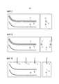
фиг.7-11 - различные выполнения соответствующего изобретению устройства.7-11 are various embodiments of the device of the invention.
На чертежах соответствующие части снабжены одинаковыми ссылочными позициями. Детально не показанные части относятся к общеизвестному уровню техники.In the drawings, the corresponding parts are provided with the same reference numerals. The parts not shown in detail are of the prior art.
Фиг.1 показывает в схематичном представлении устройство для добычи на месте залегания (in-situ) углеводородсодержащего вещества из подземного месторождения 6 в качестве резервуара при снижении его вязкости, причем для этого наряду с индуктивным нагреванием резервуара посредством индукторов 10 также предусмотрена подача растворителей. Такое устройство может представлять собой, например, устройство для добычи битума из залежей нефтеносного песка. Месторождение 6 может представлять собой, в частности, месторождение нефтеносного песка или месторождение горючего сланца, из которого могут добываться битум или другие тяжелые фракции нефти.Figure 1 shows in a schematic representation a device for in situ production of a hydrocarbon-containing substance from an
Согласно фиг.1 имеется проводящий шлейф, который функционирует посредством источника электропитания 1. Участки проводящего шлейфа, которые действуют как электроды, указываются как индукторы 10. Они представляют собой участки, проходящие горизонтально и параллельно в месторождении 6.According to figure 1 there is a conductive loop that operates by means of the power source 1. The sections of the conductive loop that act as electrodes are indicated as
Устройство для добычи на месте залегания (in-situ) углеводородсодержащего вещества имеет упомянутый индуктор 10, который проходит в скважинах внутри месторождения 6. Индуктор 10 или его участки следует рассматривать как проводник, который образует проводящий шлейф. Замкнутый проводящий шлейф состоит из двух проходящих в месторождении 6 прямого и обратного проводников индуктора 10, а также из участков 11 проводника, которые не действуют или действуют в малой степени как нагрев и проходят на земной поверхности или от земной поверхности 5 в месторождение 6, чтобы гарантировать токоподвод для индуктора 10. На чертеже, например, оба конца проводящего шлейфа размещены на земной поверхности. На правой стороне на чертеже шлейф просто замкнут - см. участок 11 проводника на чертеже. На левой стороне находится источник 1 электропитания, включая все необходимые электрические устройства, такие как инвертор и генератор, посредством которых необходимый ток и необходимое напряжение прикладывается к проводящему шлейфу, чтобы индукторы 10 служили как проводники для электрического/электромагнитного нагрева для генерации тепла в месторождении 6.A device for in situ production of a hydrocarbon-containing substance has the mentioned
Индукторы 10 по отношению к по меньшей мере частям месторождения 6 действуют в качестве индуктивного электрического нагрева. За счет проводимости по меньшей мере частей месторождения 6 последнее может нагреваться с помощью по существу концентрически вокруг обоих по возможности параллельно проходящих участков индуктора 10.
Индуктор 10 может представлять собой, в частности, стержнеобразный металлический проводник или скрученный металлический кабель из особенно хорошо проводящего металла, который выполнен как резонансный контур.The
На чертеже не показан продуктопровод, по которому извлеченное из месторождения 6 углеродсодержащее вещество собирается и из месторождения 6 транспортируется на земную поверхность 5.The drawing does not show the product pipeline through which the carbon-containing substance extracted from
Для уменьшения вязкости добываемого вещества в резервуаре предусмотрено только одно устройство, посредством которого в резервуар вводится растворитель-флюид. Имеется накопитель 3 для предоставления растворителя-флюида 14 - на чертеже показан как жидкость, однако он может представлять собой также газ, многокомпонентную смесь или смесь фаз, которая предусматривается как инжектируемый флюид. Этот флюид 14 посредством насоса 2 - или в случае газообразного флюида посредством компрессора - вводится во флюидную систему, которая состоит из трубопроводов 13 флюида и из направляющей 12 флюида. Направляющая 12 флюида должна при этом соответствовать участкам флюидной системы, проходящим горизонтально и параллельно в месторождении 6. Трубопроводы 13 флюида согласно чертежу включают в себя систему шлангов/труб над земной поверхностью 5 или соединение с горизонтально проходящей направляющей 12 флюида.To reduce the viscosity of the produced substance, only one device is provided in the reservoir by means of which solvent fluid is introduced into the reservoir. There is a reservoir 3 for providing
Подача осуществляется в предложенном примере, в отличие от фиг.1, слева в плоскости чертежа. Направляющая 12 флюида имеет в горизонтальном подземном участке перфорацию 21 или распределенным образом расположенные форсунки, через которые флюид 22 может выступать в резервуар (на фигуре показано стрелками). Кроме того, в предложенном примере направляющая 12 флюида заканчивается под землей. Для этого предусмотрено окончание 23 направляющей 12 флюида, причем это окончание также может иметь перфорацию.The feed is carried out in the proposed example, in contrast to figure 1, to the left in the plane of the drawing. The
Согласно чертежу проводящий шлейф вдоль длины индуктора 10 почти полностью коаксиально окружен направляющей 12 флюида, так что индуктор 10 - или оболочка индуктора 10 - при работе окружены флюидом. В идеальном случае индуктор 10 встроен в направляющую 12 флюида и может прокладываться как единый узел. Различные выполнения подобных комбинированных проводников и направляющих 12 флюида поясняются ниже со ссылками на фиг.2-11.According to the drawing, the conductive loop along the length of the
При работе флюид посредством насоса 2 или подобным образом действующего устройства вводится во флюидную систему. Давление остается до перфорированной части направляющей 12 флюида по существу неизменным, так как до начала работы направляющей 12 флюида не предусматривается никакой выпуск флюида. Если теперь поданный флюид достигает участка с выполненной согласно изобретению перфорированной направляющей 12 флюида, то часть флюида через перфорацию 21 вводится в месторождение 6. Другая часть флюида течет дальше вдоль направляющей 12 флюида, причем на участках постоянно часть флюида выходит через перфорацию 21. Тем самым имеет место уменьшение транспортируемого флюида за счет выпущенного флюида 22. Потеря флюида в направляющей 12 флюида восполняется с помощью насоса 2.During operation, fluid is introduced into the fluid system by means of a pump 2 or a similarly acting device. The pressure remains substantially unchanged until the perforated portion of the
В частности, достигается эффект, состоящий в том, что флюид течет в окружающую среду индуктора 10 в месторождение 6, за счет чего вязкость в месторождении 6 снижается и/или давление в месторождении 6 повышается. В особенности может компенсироваться спадающее давление из-за транспортировки углеводородсодержащего вещества. Кроме того, в зависимости от состава флюида также электрическая проводимость в месторождении 6, в частности в окружении индукторов 10, может повышаться или снижаться, что при повышении вновь повышает эффективность индукторов 10. При снижении проводимости плотность мощности нагрева в непосредственном окружении индуктора 10 может снижаться, чтобы снизить его термическую нагрузку.In particular, an effect is achieved in that the fluid flows into the environment of the
Завершение 23, размеры направляющей 12 флюида, выполнение перфорации 21 и давление, прикладываемое через насос 2 к флюиду, должны были бы предпочтительным образом таким образом согласовываться друг с другом, в частности, также с учетом имеющейся информации о породах и глубине месторождения, чтобы упомянутые эффекты проявлялись по существу по всей длине горизонтально проходящего индуктора 10 и/или чтобы флюид 22 равномерно выходил в месторождение.The
Применяемое давление зависит от глубины месторождения, то есть от расстояния от горизонтально проложенных индукторов 10 до земной поверхности 5. Давление должно быть выше, чем гидростатическое давление соответствующего водяного столба, и находится, например, в диапазоне от 5000 ГПа (5 бар) до 50000 ГПа (50 бар).The pressure used depends on the depth of the field, that is, on the distance from the horizontally laid
Снижение давления в месторождении 6 предпринимается таким образом, что к моменту времени, при котором давление на покрывающую породу, имеющуюся выше месторождения 6, становится слишком высоким, продуктопровод(ы) (не показан(ы)) открывается(ются). Однако может быть предпочтительным поддерживать продуктопроводы закрытыми по возможности дольше, чтобы достичь высокого давления в резервуаре 6.The pressure reduction in the
Для оптимизации давлений могут использоваться так называемые «искусственные всасывающие насосы», которые оказывают влияние на так называемое давление «по всему основанию» и с помощью которых может осуществляться транспорт производимого продукта из резервуара с помощью продуктопровода.To optimize pressures, the so-called “artificial suction pumps” can be used, which influence the so-called pressure “all over the base” and with the help of which the produced product can be transported from the tank using the product pipeline.
Функцией выступающего флюида 22 является, таким образом, как снижение вязкости, повышение или поддержание давления в месторождении 6, так и вытеснение (вымывание) добываемого вещества, причем достигается предотвращение пониженного давления в месторождении 6.The function of the protruding
В качестве растворителя-флюида могут, например, применяться газы, например этан, пропан, бутан, СО2, SO2 и т.д., а также жидкости, например полимеры или водные смеси с полимерами. Кроме того, возможны многокомпонентные смеси. Эти растворители поступают в соответствии с данным способом в резервуар, растворяются в битуме месторождения и уменьшают его вязкость. Кроме того, растворители могут объединяться или смешиваться, например пропан в качестве растворителя может смешиваться с другими газами (например, метаном), чтобы обеспечивать необходимый для вытеснения нефти объемный поток (расход) и давление.As the solvent fluid, for example, gases such as ethane, propane, butane, CO 2 , SO 2 , etc., as well as liquids, for example polymers or aqueous mixtures with polymers can be used. In addition, multicomponent mixtures are possible. These solvents enter the tank in accordance with this method, dissolve in the bitumen of the deposit and reduce its viscosity. In addition, the solvents can be combined or mixed, for example propane as a solvent can be mixed with other gases (for example, methane) to provide the necessary volumetric flow (flow) and pressure for oil displacement.
На фиг.2 схематично показан в пространственном представлении участок индуктора 10 с окружающей направляющей 12 флюида, причем показанный участок не имеет выпускных отверстий в направляющей 12 флюида. Индуктор 10, расположенный по центру выполненной в форме шланга оболочки 15 направляющей 12 флюида, окружен направляющей 12 флюида. Позиционирование индуктора 10 может, например, определяться только усилиями протекающего флюида в направляющей 12 флюида. В этом случае, как показано на фиг.2, можно отказаться от центрирования. Индуктор 10 в соответствии с этим является в значительной степени свободно подвижным в направляющей 12 флюида и может, например, ввиду силы тяжести внутри лежать на оболочке, окружающей флюид. Для конкретного позиционирования или фиксации в направляющей 12 флюида далее предоставляются различные формы выполнения.Figure 2 schematically shows in spatial representation a portion of the
Диаметр индуктора 10 может предпочтительно составлять от 30 до 100 мм. Ширина кольцевого зазора индуктора 10 предпочтительно составляет от 5 мм до 50 мм.The diameter of the
Далее объясняются схематично показанные сечения проводников, комбинированных с направляющей флюида. Сечение выполняется вдоль секущей плоскости, которая проходит под прямым углом к протяженности направляющей флюида.Next, schematically shown cross-sections of conductors combined with a fluid guide are explained. The section is performed along the secant plane, which runs at right angles to the length of the fluid guide.
Согласно фиг.3 осуществляется опирание индуктора 10 с помощью, например, звездообразных распорных держателей - перемычек 16, причем предпочтительно применяется от двух до пяти распорных держателей. Однако также возможно решение с только одной перемычкой 16. Перемычки 16 предпочтительно прикреплены к внутренней стенке оболочки 15 и в центре соединены через стабилизаторы 17 или непосредственно с внешней оболочкой индуктора 10. Индуктор 10 находится коаксиально в центре оболочки 16 направляющей 12 флюида и прокладывается как единый узел с оболочкой 15 и перемычками 16 или заливается дополнительно.According to FIG. 3, the
Направляющая 12 флюида образуется из полостей внутри оболочки 15.A
Ширина перемычек 16 может лежать, например, в диапазоне 5-30 мм, чтобы потери давления флюида в направляющей 12 флюида не становились слишком большими.The width of the
Согласно фиг.4 в кольцевой полости, то есть внутри внешней оболочки 20, вокруг индуктора 10 предусмотрено несколько шлангов или труб 12А, 12В, …, 12F в качестве направляющей 12 флюида.According to figure 4, in the annular cavity, that is, inside the
Согласно фиг.5 представлен еще один вариант, при котором центральный, направляющий растворитель-флюид шланг или труба в качестве направляющей 12 флюида окружен частичными проводниками 10А, 120В, …. При этом частичные проводники 10А, 120В, … представляют, при совместном рассмотрении, индуктор 10. Совместно частичные проводники 10А, 120В, … и направляющая 12 флюида окружены внешней оболочкой.According to FIG. 5, another embodiment is presented in which a central solvent-fluid-guiding hose or pipe as a
В то время как выше до сих пор пояснялось только направление флюида, далее внимание будет сконцентрировано на другом существенном аспекте, состоящем в том, что через направляющую 12 флюида флюид выдается в месторождение 6. Например, это может происходить через конец инжектора или по длине направляющей 12 флюида. Показанные на фиг.2-5 сечения, если явно не упоминается, применимы для участков направляющей 12 флюида, на которых флюид 22 должен выходить наружу.While only the direction of the fluid has been explained so far, further attention will be focused on another significant aspect, namely that the fluid is discharged through the
На фиг.6 схематично показан участок индуктора 10 с окружающей направляющей флюида в пространственном представлении, причем направляющая 12 флюида выполнена перфорированной, так что транспортируемый флюид может выходить наружу, причем флюид может выходить как газ, или жидкость, или многокомпонентная смесь.6 schematically shows a portion of the
Аналогично фиг.2, индуктор 10, расположенный по центру оболочки 15, выполненной в форме шланга, окружен направляющей 12 флюида. В отличие от выполнения согласно фиг.2 направляющая 12 флюида или оболочка 15 имеет перфорацию 12, состоящую из множества отверстий и проходов, через которые транспортируемый флюид может проникать изнутри наружу. Величина, положение и частота отверстий должны быть согласованы с желательными условиями и с помощью представления на фиг.7 не должны интерпретироваться как ограничивающие.Similarly to FIG. 2, an
Отверстия перфорации 21 могут при этом располагаться симметрично по всей окружности оболочки 15. Однако также может быть предпочтительным предусмотреть неравномерное распределение. Также по длине направляющей 12 флюида распределение и/или выполнение отверстий могут изменяться, в частности, так как давление внутри направляющей 12 флюида, ввиду выпущенного флюида, может изменяться.The perforation holes 21 may be located symmetrically around the entire circumference of the
Флюид, выходящий в месторождение 6 в окружении индуктора 10, имеет при этом преимущество в отношении того, что тем самым в резервуар может инжектироваться растворитель, за счет чего, с одной стороны, может быть снижена вязкость в месторождении 6, а с другой стороны, может обеспечиваться повышенное давление внутри месторождения 6. Оба эффекта обеспечивают то, что транспортируемое количество и/или скорость транспортировки добываемого углеводородсодержащего вещества могут быть повышены.The fluid entering the
Во всех формах выполнения изобретения - хотя частично не показанных - имеется продуктопровод для транспортировки добываемого вещества на участке грунта. По продуктопроводу может транспортироваться поток продукта в форме смеси жидкости, твердого вещества и газа, то есть смеси фаз, на наземную поверхность для подготовки. Далее со ссылками на схематичные чертежи поясняются различные выполнения, которые различаются по размещению индукторов, инжекторов флюида и продуктопровода.In all forms of carrying out the invention - although not partially shown - there is a product pipeline for transporting the produced substance on the ground. A product stream in the form of a mixture of a liquid, a solid substance and a gas, i.e. a mixture of phases, can be transported through a product pipeline to a ground surface for preparation. Next, with reference to the schematic drawings, various embodiments are explained, which differ in the arrangement of inductors, fluid injectors and product piping.
Согласно фиг.7, аналогично фиг.1, представлен комбинированный инжектор-индуктор на двух различных видах. Направляющая 12 флюида вновь окружает проводник 10 и проходит горизонтально внутри месторождения. Кроме того, предусмотрен продуктопровод 39, по существу по вертикали ниже комбинированного инжектора-индуктора.According to Fig.7, similarly to Fig.1, presents a combined injector-inductor in two different types. The
Фиг.8 показывает вариант относительно фиг.7, в котором представлены проходящие параллельно друг другу проводники 10 - прямой и обратный проводники - проводящего шлейфа. Направляющая 12 флюида окружает соответственно прямой/обратный проводник 10 и проходит внутри месторождения горизонтально. В этом примере выполнения продуктопровод 39 размещен предпочтительным образом посредине между проводниками 10, однако вновь ниже плоскости проложенных проводников 10. В плоскости сечения перпендикулярно направлению протяженности проводников и труб размещены пары 10, 12 комбинированных инжекторов-индукторов, таким образом, по существу в V-образной форме. Аналогичным образом продуктопровод 39 может позиционироваться между двумя проводящими шлейфами (например, между прямым проводником первого проводящего шлейфа и обратным проводником другого второго проводящего шлейфа) также в V-образной форме.Fig. 8 shows a variant with respect to Fig. 7, in which
Фиг.9-11 показывают формы выполнения, в которых проводники 10 сформированы не как единый узел с направляющей 12 флюида, а проложены отдельно.Figures 9-11 show embodiments in which the
Согласно фиг.9 проводники 10 и продуктопровод 39 вновь проложены горизонтально в месторождении. Кроме того, продуктопровод 39 размещен по существу вертикально ниже проводника 10. Направляющая 12 флюида ориентирована, например, по вертикали в месторождении, причем предпочтительно несколько направляющих 12 флюида могут быть предусмотрены на расстоянии друг от друга. Растворитель транспортируется по направляющим 12 флюида в вертикальном направлении в резервуар, причем растворитель предпочтительно может выступать только из наконечника соответствующей направляющей 12 флюида. Этот наконечник в предпочтительной форме выполнения позиционирован на некотором расстоянии от проводника 10 по вертикали над проводником 10.According to Fig.9, the
На фиг.10 показана форма выполнения, в которой проводник 10, продуктопровод 39 и направляющая 12 флюида выполнены как отдельные компоненты, однако в своей пространственной ориентации по существу выполнены в одинаковой форме. Все компоненты проходят внутри месторождения по существу горизонтально. Направляющая 12 флюида размещена по вертикали над проводником 10, который вновь расположен по вертикали над продуктопроводом 39.Figure 10 shows a form of execution in which the
На фиг.11 вновь показана форма выполнения, в которой проводник 10, продуктопровод 39 и направляющая 12 флюида выполнены как отдельные компоненты и в своей пространственной ориентации по существу выполнены в одинаковой форме, причем все компоненты проходят внутри месторождения по существу горизонтально. Проводящий шлейф выполнен как пара проводников, причем проводник 10 пары проводников размещен в значительной мере в горизонтальной плоскости. Предусмотрены два продуктопровода 39, которые предпочтительно расположены также в горизонтальной плоскости, причем соответствующий из продуктопроводов 39 расположен по существу по вертикали под одним из проводников 10. Направляющая 12 флюида находится в этой форме выполнения в центральной области между проводниками 10 и продуктопроводами 39, под проводниками 10, над продуктопроводами 39 и по существу посредине между парами проводников или парами продуктопроводов.11 again shows a form of execution in which the
Все формы выполнения имеют общее в том, что используется электромагнитно-индуктивный нагрев для нагревания месторождения нефти, поддерживаемый инжекцией растворителя.All forms of execution are common in that electromagnetic induction heating is used to heat the oil field, supported by solvent injection.
Инжекция растворителя является предпочтительно непрерывной, без временного прерывания. Инжекция растворителя, в зависимости от потребности, может также применяться для предварительной подготовки месторождения, например инжекция осуществляется перед действительным рабочим процессом добычи, чтобы снизить вязкость нефти вблизи продуктопровода. Тем самым потребление энергии применяемого предварительного нагрева месторождения снижается или даже исключается.The injection of the solvent is preferably continuous without interruption. Solvent injection, depending on need, can also be used for preliminary preparation of the field, for example, injection is carried out before the actual production workflow to reduce the viscosity of the oil near the product pipeline. Thus, the energy consumption of the applied pre-heating of the field is reduced or even eliminated.
За счет применения флюидов - газообразных или жидких, однофазных или в качестве смеси - дополнительно к индуктивному нагреву, с одной стороны, дополнительно снижается вязкость нефти, а с другой стороны, обеспечивается возможность вытеснения нефти из месторождения. Общее потребление энергии для добычи нефти или битума за счет этого снижается. За счет того, что можно отказаться от ввода водяного пара, обеспечивается возможность пониженного потребления воды и меньшие затраты установки для обработки производимой воды. Кроме того, может достигаться ускорение добычи или увеличение доли добычи.Due to the use of fluids - gaseous or liquid, single-phase or as a mixture - in addition to inductive heating, on the one hand, the viscosity of the oil is further reduced, and on the other hand, it is possible to displace oil from the field. The total energy consumption for oil or bitumen production is thereby reduced. Due to the fact that it is possible to refuse the introduction of water vapor, the possibility of reduced water consumption and lower installation costs for processing produced water are provided. In addition, accelerated production or an increase in the share of production can be achieved.
Claims (13)
что проводник (10) проводящего шлейфа (10, 11) состоит из нескольких частичных проводников, которые на по меньшей мере одном участке окружают направляющую (12) флюида.2. The device according to p. 1, characterized in
that the conductor (10) of the conductive loop (10, 11) consists of several partial conductors that surround at least one portion of the fluid guide (12).
что направляющая (12) флюида выполнена как шланг и/или труба.3. The device according to any one of paragraphs. 1 or 2, characterized in that
that the fluid guide (12) is designed as a hose and / or pipe.
что шланг и/или труба размещены примерно коаксиально относительно проводника (10).4. The device according to p. 3, characterized in
that the hose and / or pipe are approximately coaxial with respect to the conductor (10).
что перфорация (21) выполнена таким образом, и/или предусмотрены средства, чтобы по существу препятствовать проникновению твердых частиц и/или песка из резервуара (6) в направляющую (12) флюида.5. The device according to any one of paragraphs. 1 or 2, characterized in that
that the perforation (21) is made in this way, and / or means are provided to substantially prevent the penetration of solid particles and / or sand from the reservoir (6) into the fluid guide (12).
что перфорация (21) выполнена с электрической изоляцией отверстий перфорации (21) относительно проводника (10).6. The device according to any one of paragraphs. 1 or 2, characterized in that
that the perforation (21) is made with electrical insulation of the perforation holes (21) relative to the conductor (10).
что перфорация (21) имеет отверстия, которые по форме, и/или величине, и/или распределению таким образом выполнены, что при подаче растворителя-флюида под заданным давлением растворитель-флюид выдается в окружающую среду направляющей (12) флюида в резервуар (6) распределенным образом по длине направляющей (12) флюида через перфорацию (21).7. The device according to any one of paragraphs. 1 or 2, characterized in that
that the perforation (21) has holes that are shaped and / or sized and / or distributed in such a way that, when the solvent-fluid is supplied under a predetermined pressure, the solvent-fluid is released into the environment of the fluid guide (12) into the reservoir (6 ) in a distributed manner along the length of the fluid guide (12) through perforation (21).
что растворитель-флюид под давлением направляется в направляющую (12) флюида, так что внутри направляющей (12) флюида в зоне перфорации (21) имеется давление, большее, чем давление в резервуаре (6), предпочтительно гидростатическое давление в окружающей среде перфорации (21).9. The method according to p. 8, characterized in that
that the solvent fluid is directed under pressure into the fluid guide (12), so that inside the fluid guide (12) in the perforation zone (21) there is a pressure greater than the pressure in the reservoir (6), preferably the hydrostatic pressure in the perforation environment (21) )
в качестве растворителя-флюида предусмотрены газ, или жидкость, или многокомпонентная смесь, в частности, включая по меньшей мере один из следующих компонентов:
- алканы, например метан, и/или пропан, и/или бутан, и/или этан;
- водные смеси с содержащимися в них смачивающими веществами (например, поверхностно-активными веществами);
- водные смеси с содержащимися в них полимерами;
- кислоты;
- основания;
- SO2;
- CO2.11. The method according to any one of paragraphs. 8-10, characterized in that
as a solvent fluid, a gas or liquid or a multicomponent mixture is provided, in particular including at least one of the following components:
- alkanes, for example methane, and / or propane, and / or butane, and / or ethane;
- aqueous mixtures with the wetting agents contained therein (for example, surfactants);
- water mixtures with the polymers contained in them;
- acids;
- grounds;
- SO 2 ;
- CO 2.
Applications Claiming Priority (3)
| Application Number | Priority Date | Filing Date | Title |
|---|---|---|---|
| DE102010008779A DE102010008779B4 (en) | 2010-02-22 | 2010-02-22 | Apparatus and method for recovering, in particular recovering, a carbonaceous substance from a subterranean deposit |
| DE102010008779.3 | 2010-02-22 | ||
| PCT/EP2010/068731 WO2011101055A2 (en) | 2010-02-22 | 2010-12-02 | Device and method for the recovery, in particular in situ recovery, of a carbonaceous substance from subterranean formations |
Publications (2)
| Publication Number | Publication Date |
|---|---|
| RU2012140494A RU2012140494A (en) | 2014-03-27 |
| RU2587196C2 true RU2587196C2 (en) | 2016-06-20 |
Family
ID=44356608
Family Applications (2)
| Application Number | Title | Priority Date | Filing Date |
|---|---|---|---|
| RU2012140494/03A RU2587196C2 (en) | 2010-02-22 | 2010-12-02 | DEVICE AND METHOD FOR PRODUCTION, PARTICULARLY PRODUCTION AT DEPOSIT (in-situ), OF CARBON-CONTAINING SUBSTANCE FROM UNDERGROUND DEPOSIT |
| RU2012140479/03A RU2586344C2 (en) | 2010-02-22 | 2011-01-31 | APPARATUS AND METHOD FOR PRODUCTION, PARTICULARLY in situ PRODUCTION OF CARBONACEOUS MATERIAL FROM UNDERGROUND RESERVOIR |
Family Applications After (1)
| Application Number | Title | Priority Date | Filing Date |
|---|---|---|---|
| RU2012140479/03A RU2586344C2 (en) | 2010-02-22 | 2011-01-31 | APPARATUS AND METHOD FOR PRODUCTION, PARTICULARLY in situ PRODUCTION OF CARBONACEOUS MATERIAL FROM UNDERGROUND RESERVOIR |
Country Status (7)
| Country | Link |
|---|---|
| US (2) | US9322255B2 (en) |
| EP (2) | EP2510188B1 (en) |
| BR (2) | BR112012020949A2 (en) |
| CA (2) | CA2790597C (en) |
| DE (1) | DE102010008779B4 (en) |
| RU (2) | RU2587196C2 (en) |
| WO (2) | WO2011101055A2 (en) |
Families Citing this family (14)
| Publication number | Priority date | Publication date | Assignee | Title |
|---|---|---|---|---|
| DE102010023542B4 (en) | 2010-02-22 | 2012-05-24 | Siemens Aktiengesellschaft | Apparatus and method for recovering, in particular recovering, a carbonaceous substance from a subterranean deposit |
| EP2886793A1 (en) * | 2013-12-18 | 2015-06-24 | Siemens Aktiengesellschaft | Method for introducing an inductor loop into a rock formation |
| DE102014223621A1 (en) * | 2014-11-19 | 2016-05-19 | Siemens Aktiengesellschaft | deposit Heating |
| US10760392B2 (en) | 2016-04-13 | 2020-09-01 | Acceleware Ltd. | Apparatus and methods for electromagnetic heating of hydrocarbon formations |
| DE102016118282A1 (en) | 2016-09-27 | 2018-03-29 | Geo Exploration Solutions Fzc | Process for increasing the oil yield |
| US10669814B2 (en) | 2017-08-08 | 2020-06-02 | Saudi Arabian Oil Company | In-situ heating fluids with electromagnetic radiation |
| CA3083568C (en) * | 2019-06-27 | 2021-07-06 | Eavor Technologies Inc. | Guidance method for multilateral directional drilling |
| US11739624B2 (en) | 2019-11-01 | 2023-08-29 | 102062448 Saskatchewan Ltd. | Processes and configurations for subterranean resource extraction |
| US11187044B2 (en) | 2019-12-10 | 2021-11-30 | Saudi Arabian Oil Company | Production cavern |
| CA3183639A1 (en) * | 2020-06-24 | 2021-12-30 | Lynn P. Tessier | Methods of providing wellbores for electromagnetic heating of underground hydrocarbon formations and apparatus thereof |
| US11460330B2 (en) | 2020-07-06 | 2022-10-04 | Saudi Arabian Oil Company | Reducing noise in a vortex flow meter |
| RU201194U1 (en) * | 2020-08-04 | 2020-12-02 | Федеральное государственное бюджетное образовательное учреждение высшего образования "Тюменский индустриальный университет" (ТИУ) | HEATER |
| US11725504B2 (en) | 2021-05-24 | 2023-08-15 | Saudi Arabian Oil Company | Contactless real-time 3D mapping of surface equipment |
| US11619097B2 (en) | 2021-05-24 | 2023-04-04 | Saudi Arabian Oil Company | System and method for laser downhole extended sensing |
Citations (6)
| Publication number | Priority date | Publication date | Assignee | Title |
|---|---|---|---|---|
| US4084637A (en) * | 1976-12-16 | 1978-04-18 | Petro Canada Exploration Inc. | Method of producing viscous materials from subterranean formations |
| RU2139415C1 (en) * | 1998-01-21 | 1999-10-10 | Башкирский государственный университет | Method for recovery of minerals |
| CA2304938A1 (en) * | 1999-08-31 | 2001-02-28 | Suncor Energy Inc. | Slanted well enhanced extraction process for the recovery of heavy oil and bitumen using heat and solvent |
| RU2231631C1 (en) * | 2002-12-15 | 2004-06-27 | Дыбленко Валерий Петрович | Method of development of an oil pool |
| DE102007008292A1 (en) * | 2007-02-16 | 2008-08-21 | Siemens Ag | Hydrocarbon-containing substance extraction device, has production pipeline, and injection pipeline including active area designed as induction heater with respect to environment of active area in underground deposits |
| DE102007040606B3 (en) * | 2007-08-27 | 2009-02-26 | Siemens Ag | Method and device for the in situ production of bitumen or heavy oil |
Family Cites Families (21)
| Publication number | Priority date | Publication date | Assignee | Title |
|---|---|---|---|---|
| US4037655A (en) | 1974-04-19 | 1977-07-26 | Electroflood Company | Method for secondary recovery of oil |
| US4010799A (en) * | 1975-09-15 | 1977-03-08 | Petro-Canada Exploration Inc. | Method for reducing power loss associated with electrical heating of a subterranean formation |
| US4362610A (en) * | 1978-06-08 | 1982-12-07 | Carpenter Neil L | Apparatus for recovery of hydrocarbons from tar-sands |
| US4612989A (en) * | 1985-06-03 | 1986-09-23 | Exxon Production Research Co. | Combined replacement drive process for oil recovery |
| US5916529A (en) * | 1989-07-19 | 1999-06-29 | Chevron U.S.A. Inc | Multistage moving-bed hydroprocessing reactor with separate catalyst addition and withdrawal systems for each stage, and method for hydroprocessing a hydrocarbon feed stream |
| BR9005628C1 (en) * | 1990-11-07 | 2000-01-25 | Petroleo Brasileiro Sa | Clearing method for flexible underwater lines. |
| RU2010954C1 (en) * | 1991-04-22 | 1994-04-15 | Татарский научно-исследовательский и проектный институт нефтяной промышленности | Induction heater |
| RU2139416C1 (en) | 1998-03-18 | 1999-10-10 | Предприятие по добыче, переработке и транспортировке газа "Севергазпром" | Method for operational control of gas-lift well |
| RU2200228C2 (en) * | 2001-04-20 | 2003-03-10 | Дрягин Вениамин Викторович | Down-hole induction heater |
| WO2002089532A1 (en) * | 2001-04-26 | 2002-11-07 | Phifer Smith Corporation | A method and apparatus for heating a gas-solvent solution |
| US6631761B2 (en) * | 2001-12-10 | 2003-10-14 | Alberta Science And Research Authority | Wet electric heating process |
| WO2005084378A2 (en) * | 2004-03-05 | 2005-09-15 | Board Of Regents Of University Of Texas System | Material and device properties modification by electrochemical charge injection in the absence of contacting electrolyte for either local spatial or final states |
| JP4794550B2 (en) | 2004-04-23 | 2011-10-19 | シエル・インターナシヨナル・リサーチ・マートスハツペイ・ベー・ヴエー | Temperature limited heater used to heat underground formations |
| WO2006016651A1 (en) | 2004-08-12 | 2006-02-16 | Sony Corporation | Print control device, printing device, print control method, program, and data structure |
| US20060131022A1 (en) * | 2004-12-17 | 2006-06-22 | Bj Services Company | Matrix treatment of damaged sandstone formations using buffered HF-acidizing solutions |
| US7398823B2 (en) * | 2005-01-10 | 2008-07-15 | Conocophillips Company | Selective electromagnetic production tool |
| AU2008242808B2 (en) * | 2007-04-20 | 2011-09-22 | Shell Internationale Research Maatschappij B.V. | Varying properties of in situ heat treatment of a tar sands formation based on assessed viscosities |
| DE102007036832B4 (en) * | 2007-08-03 | 2009-08-20 | Siemens Ag | Apparatus for the in situ recovery of a hydrocarbonaceous substance |
| DE102007040605B3 (en) | 2007-08-27 | 2008-10-30 | Siemens Ag | Device for conveying bitumen or heavy oil in-situ from oil sand deposits comprises conductors arranged parallel to each other in the horizontal direction at a predetermined depth of a reservoir |
| DE102008062326A1 (en) * | 2008-03-06 | 2009-09-17 | Siemens Aktiengesellschaft | Arrangement for inductive heating of oil sands and heavy oil deposits by means of live conductors |
| US8448707B2 (en) * | 2009-04-10 | 2013-05-28 | Shell Oil Company | Non-conducting heater casings |
-
2010
- 2010-02-22 DE DE102010008779A patent/DE102010008779B4/en not_active Expired - Fee Related
- 2010-12-02 CA CA2790597A patent/CA2790597C/en active Active
- 2010-12-02 EP EP10788299.5A patent/EP2510188B1/en not_active Not-in-force
- 2010-12-02 BR BR112012020949A patent/BR112012020949A2/en not_active Application Discontinuation
- 2010-12-02 US US13/579,400 patent/US9322255B2/en active Active
- 2010-12-02 WO PCT/EP2010/068731 patent/WO2011101055A2/en active Application Filing
- 2010-12-02 RU RU2012140494/03A patent/RU2587196C2/en not_active IP Right Cessation
-
2011
- 2011-01-31 CA CA2790616A patent/CA2790616C/en not_active Expired - Fee Related
- 2011-01-31 WO PCT/EP2011/051279 patent/WO2011101227A2/en active Application Filing
- 2011-01-31 US US13/578,674 patent/US9574430B2/en not_active Expired - Fee Related
- 2011-01-31 BR BR112012020831A patent/BR112012020831A2/en not_active Application Discontinuation
- 2011-01-31 EP EP11701823.4A patent/EP2507474B1/en not_active Not-in-force
- 2011-01-31 RU RU2012140479/03A patent/RU2586344C2/en not_active IP Right Cessation
Patent Citations (6)
| Publication number | Priority date | Publication date | Assignee | Title |
|---|---|---|---|---|
| US4084637A (en) * | 1976-12-16 | 1978-04-18 | Petro Canada Exploration Inc. | Method of producing viscous materials from subterranean formations |
| RU2139415C1 (en) * | 1998-01-21 | 1999-10-10 | Башкирский государственный университет | Method for recovery of minerals |
| CA2304938A1 (en) * | 1999-08-31 | 2001-02-28 | Suncor Energy Inc. | Slanted well enhanced extraction process for the recovery of heavy oil and bitumen using heat and solvent |
| RU2231631C1 (en) * | 2002-12-15 | 2004-06-27 | Дыбленко Валерий Петрович | Method of development of an oil pool |
| DE102007008292A1 (en) * | 2007-02-16 | 2008-08-21 | Siemens Ag | Hydrocarbon-containing substance extraction device, has production pipeline, and injection pipeline including active area designed as induction heater with respect to environment of active area in underground deposits |
| DE102007040606B3 (en) * | 2007-08-27 | 2009-02-26 | Siemens Ag | Method and device for the in situ production of bitumen or heavy oil |
Also Published As
| Publication number | Publication date |
|---|---|
| RU2012140479A (en) | 2014-03-27 |
| US20150308248A1 (en) | 2015-10-29 |
| RU2586344C2 (en) | 2016-06-10 |
| WO2011101227A2 (en) | 2011-08-25 |
| EP2507474A2 (en) | 2012-10-10 |
| EP2507474B1 (en) | 2017-09-27 |
| US9322255B2 (en) | 2016-04-26 |
| CA2790597C (en) | 2018-03-06 |
| US9574430B2 (en) | 2017-02-21 |
| RU2012140494A (en) | 2014-03-27 |
| CA2790616A1 (en) | 2011-08-25 |
| US20130192831A1 (en) | 2013-08-01 |
| CA2790616C (en) | 2018-06-12 |
| BR112012020949A2 (en) | 2016-05-03 |
| WO2011101055A3 (en) | 2012-04-19 |
| EP2510188A2 (en) | 2012-10-17 |
| WO2011101055A2 (en) | 2011-08-25 |
| EP2510188B1 (en) | 2017-06-14 |
| DE102010008779B4 (en) | 2012-10-04 |
| DE102010008779A1 (en) | 2011-08-25 |
| BR112012020831A2 (en) | 2016-07-05 |
| WO2011101227A3 (en) | 2012-04-05 |
| CA2790597A1 (en) | 2011-08-25 |
Similar Documents
| Publication | Publication Date | Title |
|---|---|---|
| RU2587196C2 (en) | DEVICE AND METHOD FOR PRODUCTION, PARTICULARLY PRODUCTION AT DEPOSIT (in-situ), OF CARBON-CONTAINING SUBSTANCE FROM UNDERGROUND DEPOSIT | |
| US8091632B2 (en) | Method and device for the in-situ extraction of a hydrocarbon-containing substance from an underground deposit | |
| RU2579058C2 (en) | Carbon-bearing substance production device and method, especially in-situ production device and method, from underground deposit | |
| RU2426868C1 (en) | Device for extraction of hydrocarbon containing substance in places of natural bedding | |
| RU2524584C2 (en) | Systems and methods for underground seam processing with help of electric conductors | |
| RU2499886C2 (en) | Plant for on-site production of substance containing hydrocarbons | |
| US8607862B2 (en) | Method and device for in-situ conveying of bitumen or very heavy oil | |
| US10087715B2 (en) | Arrangement and method for introducing heat into a geological formation by means of electromagnetic induction | |
| US9422798B2 (en) | Hydrocarbon resource heating apparatus including ferromagnetic transmission line and related methods | |
| US8978756B2 (en) | Hydrocarbon processing apparatus including resonant frequency tracking and related methods | |
| US11346196B2 (en) | Method and apparatus for complex action for extracting heavy crude oil and bitumens using wave technologies | |
| Yadali Jamaloei | Electromagnetic heating for heavy-oil and bitumen recovery: experimental, numerical, and pilot studies | |
| CA2790618A1 (en) | Device and method for obtaining, especially in-situ, a carbonaceous substance from an underground deposit | |
| US20140251597A1 (en) | Apparatus for heating hydrocarbon resources with magnetic radiator and related methods |
Legal Events
| Date | Code | Title | Description |
|---|---|---|---|
| MM4A | The patent is invalid due to non-payment of fees |
Effective date: 20191203 |