EP2509240B1 - Receiver devices and receiving methods - Google Patents
Receiver devices and receiving methods Download PDFInfo
- Publication number
- EP2509240B1 EP2509240B1 EP10834363.3A EP10834363A EP2509240B1 EP 2509240 B1 EP2509240 B1 EP 2509240B1 EP 10834363 A EP10834363 A EP 10834363A EP 2509240 B1 EP2509240 B1 EP 2509240B1
- Authority
- EP
- European Patent Office
- Prior art keywords
- signal
- carrier
- output
- transmission path
- estimation
- Prior art date
- Legal status (The legal status is an assumption and is not a legal conclusion. Google has not performed a legal analysis and makes no representation as to the accuracy of the status listed.)
- Active
Links
Images









Classifications
-
- H—ELECTRICITY
- H04—ELECTRIC COMMUNICATION TECHNIQUE
- H04L—TRANSMISSION OF DIGITAL INFORMATION, e.g. TELEGRAPHIC COMMUNICATION
- H04L27/00—Modulated-carrier systems
- H04L27/26—Systems using multi-frequency codes
- H04L27/2601—Multicarrier modulation systems
- H04L27/2647—Arrangements specific to the receiver only
- H04L27/2655—Synchronisation arrangements
- H04L27/2657—Carrier synchronisation
-
- H—ELECTRICITY
- H04—ELECTRIC COMMUNICATION TECHNIQUE
- H04L—TRANSMISSION OF DIGITAL INFORMATION, e.g. TELEGRAPHIC COMMUNICATION
- H04L25/00—Baseband systems
- H04L25/02—Details ; arrangements for supplying electrical power along data transmission lines
- H04L25/03—Shaping networks in transmitter or receiver, e.g. adaptive shaping networks
- H04L25/03006—Arrangements for removing intersymbol interference
- H04L25/03821—Inter-carrier interference cancellation [ICI]
-
- H—ELECTRICITY
- H04—ELECTRIC COMMUNICATION TECHNIQUE
- H04L—TRANSMISSION OF DIGITAL INFORMATION, e.g. TELEGRAPHIC COMMUNICATION
- H04L27/00—Modulated-carrier systems
- H04L27/26—Systems using multi-frequency codes
- H04L27/2601—Multicarrier modulation systems
- H04L27/2647—Arrangements specific to the receiver only
- H04L27/2655—Synchronisation arrangements
- H04L27/2662—Symbol synchronisation
- H04L27/2665—Fine synchronisation, e.g. by positioning the FFT window
-
- H—ELECTRICITY
- H04—ELECTRIC COMMUNICATION TECHNIQUE
- H04L—TRANSMISSION OF DIGITAL INFORMATION, e.g. TELEGRAPHIC COMMUNICATION
- H04L27/00—Modulated-carrier systems
- H04L27/26—Systems using multi-frequency codes
- H04L27/2601—Multicarrier modulation systems
- H04L27/2647—Arrangements specific to the receiver only
- H04L27/2655—Synchronisation arrangements
- H04L27/2668—Details of algorithms
- H04L27/2669—Details of algorithms characterised by the domain of operation
- H04L27/2672—Frequency domain
-
- H—ELECTRICITY
- H04—ELECTRIC COMMUNICATION TECHNIQUE
- H04L—TRANSMISSION OF DIGITAL INFORMATION, e.g. TELEGRAPHIC COMMUNICATION
- H04L27/00—Modulated-carrier systems
- H04L27/26—Systems using multi-frequency codes
- H04L27/2601—Multicarrier modulation systems
- H04L27/2647—Arrangements specific to the receiver only
- H04L27/2655—Synchronisation arrangements
- H04L27/2689—Link with other circuits, i.e. special connections between synchronisation arrangements and other circuits for achieving synchronisation
- H04L27/2691—Link with other circuits, i.e. special connections between synchronisation arrangements and other circuits for achieving synchronisation involving interference determination or cancellation
-
- H—ELECTRICITY
- H04—ELECTRIC COMMUNICATION TECHNIQUE
- H04L—TRANSMISSION OF DIGITAL INFORMATION, e.g. TELEGRAPHIC COMMUNICATION
- H04L27/00—Modulated-carrier systems
- H04L27/26—Systems using multi-frequency codes
- H04L27/2601—Multicarrier modulation systems
- H04L27/2647—Arrangements specific to the receiver only
- H04L27/2655—Synchronisation arrangements
- H04L27/2689—Link with other circuits, i.e. special connections between synchronisation arrangements and other circuits for achieving synchronisation
- H04L27/2695—Link with other circuits, i.e. special connections between synchronisation arrangements and other circuits for achieving synchronisation with channel estimation, e.g. determination of delay spread, derivative or peak tracking
-
- H—ELECTRICITY
- H04—ELECTRIC COMMUNICATION TECHNIQUE
- H04L—TRANSMISSION OF DIGITAL INFORMATION, e.g. TELEGRAPHIC COMMUNICATION
- H04L25/00—Baseband systems
- H04L25/02—Details ; arrangements for supplying electrical power along data transmission lines
- H04L25/03—Shaping networks in transmitter or receiver, e.g. adaptive shaping networks
- H04L25/03006—Arrangements for removing intersymbol interference
- H04L2025/0335—Arrangements for removing intersymbol interference characterised by the type of transmission
- H04L2025/03375—Passband transmission
- H04L2025/03414—Multicarrier
-
- H—ELECTRICITY
- H04—ELECTRIC COMMUNICATION TECHNIQUE
- H04L—TRANSMISSION OF DIGITAL INFORMATION, e.g. TELEGRAPHIC COMMUNICATION
- H04L25/00—Baseband systems
- H04L25/02—Details ; arrangements for supplying electrical power along data transmission lines
- H04L25/03—Shaping networks in transmitter or receiver, e.g. adaptive shaping networks
- H04L25/03006—Arrangements for removing intersymbol interference
- H04L2025/0335—Arrangements for removing intersymbol interference characterised by the type of transmission
- H04L2025/03426—Arrangements for removing intersymbol interference characterised by the type of transmission transmission using multiple-input and multiple-output channels
Definitions
- the present invention relates to Doppler shift correction.
- the orthogonal frequency division multiplexing (OFDM) system is a system for transmitting information on a plurality of orthogonal narrow-band carriers and is used in many communication systems such as digital wireless communication and digital terrestrial broadcasting because of its high frequency usage efficiency and good receiving performance in a multipath environment, where a plurality of reflected waves are received.
- OFDM orthogonal frequency division multiplexing
- inter-carrier interference when an OFDM signal is received in a mobile device, changes in transmission path property over time modify the orthogonality among the carriers, producing inter-carrier interference.
- the inter-carrier interference will be described with reference to FIGs. 1A and 1B . If the transmission path property is constant and does not depend on time, the carrier signals cross one another at carrier intervals at an amplitude value of "0" as shown in FIG. 1A , and one carrier does not affect adjacent carriers. If the transmission path property changes over time, as shown in FIG. 1B , a Doppler shift causes each carrier frequency to shift by a Doppler frequency (DS in FIG. 1B ), causing the carrier signals to interfere with adjacent carriers (CI in FIG. 1B ).
- DS Doppler frequency
- Patent Document 1 A method of suppressing the inter-carrier interference included in the OFDM signal is disclosed in Patent Document 1, for example.
- the inter-carrier interference cancellation method described in Patent Document 1 first estimates the transmission path property from a known signal included in the received signal and corrects the received signal in accordance with the estimation result of the transmission path property.
- the leak-in coefficient of inter-carrier interference is calculated from the temporal variation in the estimated transmission path.
- the inter-carrier interference component is estimated from the correction result of the received signal and the calculated leak-in coefficient, and the estimated inter-carrier interference component is subtracted from the received signal, thereby suppressing inter-carrier interference.
- Non-Patent Document 1 Another method of suppressing inter-carrier interference included in the OFDM signal is disclosed in Non-Patent Document 1, for example.
- the received signal is transformed to a frequency domain and then the sum with each of the adjacent carriers weighted is calculated, thereby suppressing the interference component included in each carrier.
- the weighting coefficient is calculated by using the minimum mean square error (MMSE) algorithm. Since this method not only suppresses inter-carrier interference but also combines signals (LOs in FIG. 2 ) leaking into the adjacent carriers, as shown in FIG. 2 , it is conceivable that the method improves the receiving sensitivity greater than the method described in Patent Document 1.
- MMSE minimum mean square error
- Patent Document 1 WO2007/046503 (page 35, FIG. 1 )
- Non-Patent Document 1 Mitsuru Nakayama, Masahiro Fujii, Makoto Itami, Koji Ito, "MMSE ICI canceller for OFDM Mobile Reception", Journal of the Institute of Image Information and Television Engineers, Vol. 58, No. 1, pp. 83-90 (page 87), 2004
- the inter-carrier interference cancellation method described in Patent Document 1 is a method for eliminating a leak-in component (LI in FIG. 3 ) from an adjacent carrier, as shown in FIG. 3 , there is a problem that the method also eliminates leak-out components (LOs in FIG. 3 ) into the adjacent carriers, lowering the receiving sensitivity.
- LOs in FIG. 3 leak-out components
- the inter-carrier interference cancellation method described in Non-Patent Document 1 combines the leak-out components ⁇ LOs in FIG. 2 ) into the adjacent carriers, as shown in Fig. 2 , and consequently provides a higher receiving sensitivity than the method described in Patent Document 1.
- the intercarrier interference cancellation method requires calculation of an inverse matrix of a matrix with 11 rows and 11 columns for each carrier in weighted coefficient calculation by the MMSE algorithm, there is a problem that the amount of calculation is large.
- the present invention is provided to solve the problems of the conventional technologies described above, and its object is to provide a receiving device and a receiving method that can correct a Doppler shift by a small amount of calculation and can improve receiving sensitivity.
- the present invention provides a receiving device as set out in each of Claims 1, 5, 11 and 12, and a receiving method as set out in each of Claims 6 and 10.
- Optional features are set out in the remaining claims.
- a receiving device for receiving a signal obtained by inserting a known signal into a signal obtained by frequency-multiplexing a plurality of carriers used to send transmission data, at given intervals on the time axis or a signal obtained by frequency-multiplexing by assigning a known pilot carrier to a plurality of given carriers among carriers used to send transmission data
- the receiving device including: a transmission path estimation means for estimating a transmission path property from the known signal or the known pilot carrier included in the received signal, thereby outputting a signal of estimation result of the transmission path property; an FFT computation means for transforming the received signal to a frequency domain, thereby outputting a signal of the frequency domain; a correction means for correcting distortion of the signal of the frequency domain output from the FFT computation means on the basis of the signal of estimation result of the transmission path property output from the transmission path estimation means; a leak-in coefficient calculation means for calculating an inter-carrier interference leak-in coefficient on the basis of the signal of estimation result of the transmission path property output from the transmission path
- a receiving device receives a signal obtained by inserting a known signal into a signal obtained by frequency-multiplexing a plurality of carriers used to send transmission data, at given intervals on the time axis, or a signal obtained by frequency-multiplexing by assigning a known pilot carrier to a plurality of given carriers among carriers used to send transmission data, by using a plurality of antennas
- the receiving device includes a plurality of demodulation means corresponding respectively to the plurality of antennas, a plurality of Doppler shift correction means corresponding respectively to the plurality of demodulation means, a first combining means for combining signals output from the plurality of demodulation means, and a second combining means for combining signals output from the plurality of Doppler shift correction means, each of the plurality of demodulation means comprising a transmission path estimation means for estimating a transmission path property from the known signal or the pilot carrier included in the received signal, thereby outputting a signal of estimation result of the transmission path property; and an
- a receiving device receives a signal obtained by inserting a known signal into a signal obtained by frequency-multiplexing a plurality of carriers used to send transmission data, at given intervals on the time axis, or a signal obtained by frequency-multiplexing by assigning a known pilot carrier to a plurality of given carriers among carriers used to send transmission data
- the receiving device comprises a transmission path estimation means for estimating a transmission path property from the known signal or the pilot carrier included in the received signal, thereby outputting a signal of estimation result of the transmission path property; an FFT computation means for transforming the received signal to a frequency domain, thereby outputting a signal of the frequency domain; a correction means for correcting distortion of the signal of the frequency domain output from the FFT computation means, on the basis of the signal of estimation result of the transmission path property output from the transmission path estimation means; a second leak-in coefficient calculation means for calculating an inter-carrier interference leak-in coefficient, on the basis of the signal of estimation result of the transmission path property
- a receiving device receives a signal obtained by inserting a known signal into a signal obtained by frequency-multiplexing a plurality of carriers used to send transmission data, at given intervals on the time axis, or a signal obtained by frequency-multiplexing by assigning a known pilot carrier to a plurality of given carriers among carriers used to send transmission data
- the receiving device comprises a transmission path estimation means for estimating a transmission path property from the known signal or the pilot carrier included in the received signal, thereby outputting a signal of estimation result of the transmission path property; an FFT computation means for transforming the received signal to a frequency domain, thereby outputting a signal of the frequency domain; a correction means for correcting distortion of the signal of the frequency domain output from the FFT computation means, on the basis of the signal of estimation result of the transmission path property output from the transmission path estimation means; an FFT window position detection means for detecting an FFT window position in the FFT computation means, on the basis of the signal of estimation result of the transmission path property output from
- a receiving device and a receiving method estimate desired signals included in a carrier to be demodulated and a plurality of other carries by a small amount of calculation and combine them, thereby correcting a Doppler shift and improving the receiving sensitivity.
- a receiving device and a receiving method estimate desired signals included in a carrier to be demodulated and a plurality of other carries by a small amount of calculation and combines them, thereby correcting a Doppler shift and improving the receiving sensitivity, even if the FFT window position in FFT computation required for demodulation has changed.
- y n represents an n-th carrier of the received signal
- x n represents an n-th carrier of a transmission signal
- H is a matrix representing a transmission path, including elements of i rows and j columns (i j)
- h i,j represents a leak-in coefficient from a j-th carrier to an i-th carrier
- a first term on a right side represents a signal component transmitted by the n-th carrier
- a second term on the right side represents interference components from adjacent carriers.
- an n+1-th carrier y n+1 of the received signal is expressed by equation 3 below.
- a first term on a right side is a signal component leaking from a signal transmitted by the n-th carrier to the n+1-th carrier, and a second term on the right side represents the other interference components.
- an n-1-th carrier y n-1 of the received signal is expressed by equation 4 below.
- a first term on a right side represents a signal component leaking from the signal x n transmitted by the n-th carrier to the n-1-th carrier
- a second term on the right side represents the other interference components.
- the inter-carrier interference cancellation method described in Patent Document 1 estimates the interference components represented by the second term on the right side of the equation 2, from the received signal, and eliminates the estimated interference components, thereby eliminating the leak-in components from the adjacent carriers.
- the receiving device and the receiving method according to the first embodiment are characterized in that the second term on the right side of the equation 2, the second term on the right side of the equation 3, and the second term on the right side of the equation 4 are individually from the received signal, the estimated interference components are eliminated, and thereafter the signal components, the interference components of which have been eliminated, are combined.
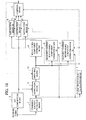
- FIG. 4 is a block diagram schematically showing structure of the receiving device according to the first embodiment.
- the receiving device according to the first embodiment includes a transmission path estimation means 1 for estimating the transmission path property from a known signal included in the received signal, an FFT computation means 2 for transforming the received signal to a frequency domain, a correction means 3 for correcting distortion in the received signal, a leak-in coefficient calculation means 4 for calculating an inter-carrier interference leak-in coefficient, an interference component estimation means 5 for estimating an interference component included in each carrier, an adjacent-carrier interference component estimation means (1) 6 for estimating an interference component other than the signal component leaking into an adjacent carrier on the right, and an adjacent-carrier interference component estimation means (2) 7 for estimating an interference component other than the signal component leaking into an adjacent carrier on the left.
- a transmission path estimation means 1 for estimating the transmission path property from a known signal included in the received signal
- an FFT computation means 2 for transforming the received signal to a frequency domain
- a correction means 3 for correcting distortion in the received
- the adjacent-carrier interference component estimation means (1) 6 and the adjacent-carrier interference component estimation means (2) 7 function as an unwanted component estimation means for estimating an unwanted component other than the signal component transmitted by the carrier to be demodulated among a plurality of carriers other than the carrier to be demodulated, on the basis of the signals output from the transmission path estimation means 1, the leak-in coefficient calculation means 4, and the correction means 3.
- the receiving device further includes a subtraction means (0) 8 for subtracting the interference component from each carrier of the received signal, a subtraction means (1) 9 for subtracting the interference component other than the signal component leaking from an adjacent carrier on the left of each carrier of the received signal, a subtraction means (2) 10 for subtracting the interference component other than the signal component leaking from an adjacent carrier on the right of each carrier of the received signal, and a combination means 11 for combining the signals output from the subtraction means (0) 8, the subtraction means (1) 9, and the subtraction means (2) 10.
- the unwanted component estimation means and a second subtraction means (subtraction means (1) 9 and subtraction means (2) 10) for subtracting the signal output from the unwanted component estimation means from the signal output from the FFT computation means 2 function as a signal component estimation means for estimating a desired signal component included in a plurality of carriers other than the carrier to be demodulated, on the basis of the signal of the frequency domain output from the FFT computation means 2, the signal of estimation result of the transmission path property output from the transmission path estimation means 1, the signal indicating the leak-in coefficient output from the leak-in coefficient calculation means 4, and the corrected signal of the frequency domain output from the correction means 3.
- the transmission path estimation means 1 in FIG. 4 estimates the transmission path property from a known signal. Estimation methods of the transmission path property are different depending on whether the known signal is a PN sequence or a pilot carrier. Next, each of the estimation methods will be described.
- the transmission path estimation means 1 first calculates a correlation between the received signal and a known PN sequence prepared beforehand (in a storage means which is not shown in the drawings) in the receiver.
- FIG. 6 shows a result of a correlation calculation in a transmission path of a two-ray ground reflection model.
- a correlation peak corresponding to the dominant wave is output;
- a correlation peak corresponding to the delayed wave is output.
- These correlation peaks are complex values representing amplitude and phase of the dominant wave and the delayed wave respectively.
- the transmission path estimation means 1 obtains the estimation result of the transmission path property acting on each carrier by transforming the results of correlation to the frequency domain.
- the transmission path estimation means 1 first transforms the received signal to the frequency domain, extracts a pilot carrier, and compares it with the pilot carrier prepared beforehand (in a storage means which is not shown in the drawings) by the receiver, thereby estimating the transmission path property acting on the pilot carrier. As shown in FIGs. 8A and 8B , the transmission path properties acting on all the carriers are estimated by interpolating the transmission path property acting on the pilot carrier in a symbol direction and in a carrier direction.
- h ⁇ n , n 1, 2, ..., N.
- This h ⁇ n , n is an estimated value of the on-diagonal element h n,n of the matrix H in the equation 1.
- This y n is the n-th carrier of the received signal and is an n-th element of a vector y representing the received signal of the equation 1.
- the correction means 3 in FIG. 4 corrects distortion of the signal output from the FFT computation means 2 in accordance with the signal output from the transmission path estimation means 1. More specifically, the correction means 3 divides the n-th carrier y n,n of the received signal by an estimation result of the transmission path property h ⁇ n , n acting on the n-th carrier. Based on the equation 2, the result of the division is expressed by equation 6 given below.
- the leak-in coefficient calculation means 4 in FIG. 4 executes calculation that is similar to calculation in the method described in Patent Document 1.
- the leak-in coefficient calculation means 4 will be described briefly below.
- FIG. 9 is a block diagram schematically showing structure of the leak-in coefficient calculation means 4.
- the leak-in coefficient calculation means 4 includes a delay means 31 for delaying the signal output from the transmission path estimation means 1 by two symbol intervals, a difference calculation means 32 for calculating a difference in estimation results of transmission path among symbols, for each carrier, and a constant matrix multiplication means 33 for multiplying the results of calculation by the difference calculation means by a constant matrix.
- Equation 9 The result obtained by multiplying H of the equation 7 by the constant matrix of the equation 8 is expressed by equation 9 below.
- the element h ⁇ i , j of the matrix K given by the equation 9 in the i-th row and the j-th column (i j) becomes the estimated value of the element h i,j of the matrix H representing the transmission path property of the equation 1 in the i-th row and the j-th column (i j).
- the leak-in coefficient calculation means 4 in FIG. 4 calculates and outputs the matrix K expressed by the equation 9.
- the interference component estimation means 5 performs calculation as expressed by equation 11 below.
- the component expressed by the equation 12 indicates the total sum of the estimated values of the leak-in components from the adjacent carriers.
- the subtraction means (0) 8 in FIG. 4 obtains the signal expressed by equation 13 below by subtracting the estimated interference component c n expressed by the equation 12 from the n-th carrier y n of the received signal expressed by the equation 2.
- the adjacent-carrier interference component estimation means 6 in FIG. 4 will be described by defining the matrix as given by equation 14 below on the basis of the equations 5 and 9.
- the element h ⁇ i , j in the i-th row and the j-th column in the equation 14 is the estimated value of the element h n,j of the matrix H representing the transmission path property defined by the equation 1 in the i-th row and the j-th column.
- the component expressed by the equation 17 is the sum of interference components other than the signal leaking from the n-th carrier to the n+1-th carrier, as shown in FIG. 10 .
- the component expressed by the equation 21 is the sum of interference components other than the signal component LO 2 leaking from the n-th carrier to the n-1-th carrier, as shown in FIG. 11 .
- the combining means 11 in FIG. 4 combines the signals output from the subtraction means (0) 8, the subtraction means (1) 9, and the subtraction means (2) 10. Letting the signals output from the subtraction means (0) 8, the subtraction means (1) 9, and the subtraction means (2) 10 be h n , n ⁇ x n , h n + 1 , n ⁇ x n , h n - 1 , n ⁇ x n respectively, the result obtained by combining the signals is expressed by equation 23 below.
- x n 1 h ⁇ n , n 2 + h ⁇ n + 1 , n 2 + h ⁇ n - 1 , n 2 ⁇ h ⁇ * n , n ⁇ h n , n ⁇ x n + h ⁇ * n + 1 , n ⁇ h n + 1 , n ⁇ x n + h ⁇ * n - 1 , n ⁇ h n - 1 , n ⁇ x n
- the outputs from the subtraction means (0) 8, the subtraction means (1) 9, and the subtraction means (2) 10 are multiplied by the corresponding estimation result of the transmission path property and the complex conjugate of the estimation result of the leak-in coefficients h ⁇ * n , n , h ⁇ * n + 1 , n , h ⁇ * n - 1 , n respectively as given by the equation 23, and then divided by h ⁇ n , n 2 + h ⁇ n + 1 , n 2 + h ⁇ n - 1 , n 2 for normalization.
- the receiving device and the receiving method according to the first embodiment can correct the Doppler shift and can improve the receiving sensitivity by extracting the individual components leaking into the adjacent carriers and combining them. Unlike Non-Patent Document 1, this process does not require the inverse matrix computation, and consequently can correct the Doppler shift by a small amount of computation.
- the equation 11 in the first embodiment indicates that if accuracy of the corrected signal x ⁇ is low, the inter-carrier interference estimation error becomes large, making it impossible to suppress the inter-carrier interference sufficiently.
- the inter-carrier interference estimation error is reduced by multiplying a signal having a low signal-to-noise power ratio by a small weighting coefficient.
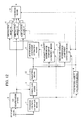
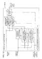
- FIG. 12 is a block diagram schematically showing structure of a receiving device according to the second embodiment.
- elements identical to or corresponding to the elements in FIG. 4 (first embodiment) will be denoted by the same reference numerals.
- the receiving device shown in FIG. 12 differs from the receiving device shown in FIG. 4 in that a weighting means 12 is included.
- the weighting means 12 will be described mainly.
- a signal transmitted by carriers of a transmission signal in the second embodiment is a complex signal obtained by multi-value digital modulation.
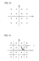
- transmission information is modulated by addressing four bits of transmission information to each of the sixteen signal points as shown in FIG. 13 , and the receiving device receives the transmission signal with noise added. If a signal point A in FIG. 14 is sent, for example, the signal point of the signal output from the correction means 3 in FIG. 12 is affected by noise and becomes a point B in FIG. 14 .
- the receiving device generally makes grid like partitions each containing a signal point of the transmission signal at its center, detects the partition containing the signal point of the signal output from the correction means 3, and judges that the transmission information is sent at the signal point corresponding the partition. This is called a hard decision.
- the signal point of the signal output from the correction means 3 is in the vicinity of the signal point of the transmission signal. As the signal-to-noise power ratio decreases, the signal point of the signal output from the correction means 3 separates from the signal point of the transmission signal. If the signal-to-noise power ratio is so low that the signal point crosses the boundary and enters an adjacent partition, an error occurs in restoration of the transmission bit.
- the weighting means 12 in FIG. 12 determines a weighting coefficient based on the idea that the corrected signal point near the boundary has a low signal-to-noise power ratio and a low reliability. More specifically, as a distance L between a signal point of the transmission signal and a signal point of the signal output from the correction means 3 increases, a smaller weighting coefficient is given, as shown in FIG. 14 .
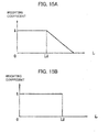
- FIGs. 15A and 15B show two examples of determining a weighting coefficient.
- FIG. 15A shows that the weighting coefficient gradually decreases if the distance between the signal point of the transmission signal and the signal point of the signal output from the correction means 3 exceeds a predetermined threshold L1.
- FIG. 15B shows that the weighting coefficient becomes 0 when the distance between the signal point of the transmission signal and the signal point of the signal output from the correction means 3 exceeds a predetermined threshold L2.
- the weighting means 12 in FIG. 12 multiplies the signal output from the correction means 3 by the weighting coefficient determined by the methods described above.
- the weighting coefficient may be multiplied after a hard decision is made on the signal output from the correction means 3.
- the receiving device and the receiving method according to the second embodiment multiply the signal output from the correction means 3 by a weighting coefficient decreasing as the distance between the signal point of the transmission signal and the signal point of the signal output from the correction means 3 increases. This reduces the inter-carrier interference estimation error, thereby allowing the Doppler shift to be corrected accurately.
- a signal output from the combining means 11 is fed back to reduce the inter-carrier interference estimation error.
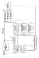
- FIG. 16 is a block diagram schematically showing structure of the receiving device according to the third embodiment.
- elements identical to or corresponding to the elements in FIG. 4 (first embodiment) will be denoted by the same reference numerals.
- the receiving device shown in FIG. 16 differs from the receiving device shown in FIG. 4 in that a switching means 13 is included.
- the switching means 13 will be described mainly.
- inter-carrier interference included in the received signal is first suppressed and the result is output from the combining means 11, as described in the first embodiment.
- the switching means 13 in FIG. 16 selects and outputs a signal input from the correction means 3.
- the signal output from the combining means 11 is fed back to the switching means 13.
- the switching means 13 selects and outputs the signal input from the combining means 11.
- the inter-carrier interference is suppressed again, and the result is output from the combining means 11.
- the receiving device and the receiving method according to the third embodiment improves the accuracy of x ⁇ in the equation 11 by feeding the signal output from the combining means 11 back and suppressing inter-carrier interference repeatedly, and consequently can correct the Doppler shift more accurately.
- Doppler shift correction in a diversity receiving device will be described, taking dual antenna diversity as an example.
- FIG. 17 is a block diagram schematically showing structure of a receiving device according to the fourth embodiment.
- the receiving device according to the fourth embodiment includes demodulation means 21 and 22 for demodulating received signals, a first combining means 23 for combining signals output from the demodulation means 21 and 22, Doppler shift correction means 24 and 25 for compensating an effect of a Doppler shift included in the signals output from the demodulation means 21 and 22, and a second combining means 26 for combining signals output from the Doppler shift correction means 24 and 25.
- FIG. 18 is a block diagram schematically showing structure of the demodulation means 21 and 22 in FIG. 17 .
- the demodulation means 21 and 22 include an FFT computation means 2 and a transmission path estimation means 1 respectively.
- the FFT computation means 2 transforms the received signal to a frequency domain
- the transmission path estimation means 1 estimates the transmission path property from a known signal included in the received signal. These means are the same as those in the first embodiment.
- the first combining means 23 in FIG. 17 combines signals obtained by performing FFT of the received signal, on the basis of the estimation result of the transmission path property obtained by the demodulation means (1) 21 and the demodulation means (2) 22.
- Generally known combining methods include selection combining, equal gain combining, and maximal ratio combining. The combining methods will be described briefly.
- Selection combining is a method of comparing
- the signals output from the demodulation means (1) 21 and the demodulation means (2) 22 are multiplied by the complex conjugate of the signal output from the transmission path estimation means 1 as a weight, and the signals are summed up, as expressed by equation 26 below.
- FIG. 17 a signal combined by the combining method expressed by any of the equations 24 - 26 is input to the Doppler shift correction means (1) 24 and the Doppler shift correction means (2) 25.
- FIG. 19 is a block diagram schematically showing structure of the Doppler shift correction means (1) 24 and the Doppler shift correction means (2) 25. The means in FIG. 19 are the same as the corresponding means in the first embodiment ( FIG. 4 ). The combined result input to the Doppler shift correction means (1) 24 and the Doppler shift correction means (2) 25 is used as x ⁇ in the equation 11 described in the first embodiment.
- the second combining means 26 in FIG. 17 combines the signals output from the combining means included in the Doppler shift correction means (1) 24 and the Doppler shift correction means (2) 25.
- the second combining means 26 uses any of the selection combining, the equal gain combining, and the maximal ratio combining, for example, as its combining method.
- the receiving device and the receiving method according to the fourth embodiment combine the signals output from a plurality of demodulation means and use the combined result as x ⁇ in the equation 11, as described above, the inter-carrier interference estimation error is reduced, and consequently the effect of the Doppler shift can be corrected more accurately.
- a receiving device and a receiving method that can correct a Doppler shift accurately even if an FFT window position changes.
- FIG. 20 is a block diagram schematically showing structure of the receiving device according to the fifth embodiment.
- elements identical to or corresponding to the elements in FIG. 4 used in the description of the first embodiment are denoted by the same reference numerals.
- elements 1, 2, 3, 5, 6, 7, 8, 9, 10, and 11 in FIG. 20 operate in a similar way to the elements having the identical reference numerals in FIG. 4 .
- the receiving device according to the fifth embodiment differs from the receiving device according to the first embodiment in that a second leak-in coefficient calculation means 100 for receiving FFT window position information and the output from the transmission path estimation means 1, instead of the leak-in coefficient calculation means 4 in the first embodiment.
- the second leak-in coefficient calculation means 100 receives an output (a signal of estimation result of the transmission path property) of the transmission path estimation means 1 and FFT window position information, corrects a phase shift in the output signal of the transmission path estimation means 1, caused by a change in the FFT window position, on the basis of the FFT window position information given from the outside, calculates the inter-carrier interference leak-in coefficient, and outputs a signal indicating the leak-in coefficient.
- FIG. 21 is a block diagram schematically showing an example of structure of the second leak-in coefficient calculation means 100 shown in FIG. 20 .
- the second leak-in coefficient calculation means 100 includes a delay means (1) 101a for outputting the output from the transmission path estimation means 1 after a delay of a single symbol interval and a delay means (2) 101b for outputting the output of the delay means (1) 101a after another delay of a single symbol interval.
- the second leak-in coefficient calculation means 100 also includes a phase correction means (1) 102a, a phase correction means (2) 102b, a difference calculation means 32, and a constant matrix multiplication means 33.
- the difference calculation means 32 and the constant matrix multiplication means 33 are the same as those described in the first embodiment ( FIG. 9 ).
- the delay means (1) 101a delays the output of the transmission path estimation means 1 by a single symbol interval, and the delay means (2) 101b delays the output of the delay means (1) 101a further by a single symbol interval.
- the phase correction means (1) 102a gives a phase rotation to the output of the transmission path estimation means 1 in accordance with the input FFT window position information.
- the FFT window position information is an input signal supplied from the outside and expresses the difference of the FFT window position in the FFT computation means 2 from the reference position or the amount of difference from the preceding symbol.
- the phase correction means (1) 102a gives the output of the transmission path estimation means 1 a reverse phase rotation from the phase rotation of the output of the transmission path estimation means 1 resulting from the difference in the FFT window position.
- the output of the phase correction means (1) 102a is a signal with the effect of the difference in FFT window position eliminated.
- the phase correction means (2) 102b corrects the phase of the output of the phase correction means (2) 102b in accordance with the FFT window position information corresponding to the output of the delay means (2) 101b.
- the signals of which phase is corrected by the phase correction means (1) 102a and the phase correction means (2) 102b respectively are converted to a leak-in coefficient by the difference calculation means 32 and the constant matrix multiplication means 33.
- the second leak-in coefficient calculation means 100 is configured to calculate the leak-in coefficient from the signal of which phase rotation resulting from the FFT window shift is corrected and is not confined to the structure shown in FIG. 21 .
- the output of the transmission path estimation means 1 is directly input to the delay means (1) 101a in FIG. 21
- the output of the transmission path estimation means 1 may be corrected by a phase correction means (not shown in the drawings), and then the corrected signal may be input to the delay means (1) 101a.
- the phase correction means (1) 102a and the phase correction means (2) 102b can be omitted.
- the second leak-in coefficient calculation means 100 may also include three or more delay means and may calculate a leak-in coefficient by using signals of estimation results of the transmission path property of three or more symbols.
- the configuration can be used if each signal of estimation result of the transmission path property is phase-corrected.
- the number of delay means may also be only one, and the leak-in coefficient may be calculated by using the signal of estimation result of the transmission path property of a single symbol.
- the second leak-in coefficient calculation means 100 can be configured by at least one delay means for outputting the output of the transmission path estimation means 1 after a delay of a single symbol interval, at least one phase correction means for giving the output of the transmission path estimation means 1 a reverse phase rotation from the phase rotation of the output of the transmission path estimation means 1 resulting from the difference from the preceding symbol or the difference from the reference FFT window position obtained as the FFT window position information, a difference calculation means 32 for calculating the difference between the signal of estimation result of the transmission path property of which phase has been corrected by the phase correction means and the signal of estimation result of the transmission path property which has been delayed by the delay means in units of symbols and has been phase-corrected by the phase correction means, and a constant matrix multiplication means 33 for multiplying the output of the difference calculation means 32 by a constant matrix.
- the leak-in coefficient is calculated from the signal in which phase rotation caused by the change in FFT window position has been corrected, so that the Doppler shift can be corrected for independently of the FFT window position, and a mobile reception capability can be improved.
- a receiving device and a receiving method according to a sixth embodiment can correct the Doppler shift accurately even if the FFT window position information is not known.
- FIG. 22 is a block diagram schematically showing structure of the receiving device according to the sixth embodiment.
- elements identical to or corresponding to the elements in FIG. 20 used to describe the fifth embodiment are denoted by the same reference numerals.
- elements 1, 2, 3, 5, 6, 7, 8, 9, 10, 11, and 100 in FIG. 22 operate in a similar way to the elements having the corresponding reference numerals in FIG. 20 .
- the receiving device according to the sixth embodiment differs from the receiving device according to the fifth embodiment in that an FFT window position detection means 103 is provided and that the FFT window position information detected by the FFT window position detection means 103 is input to the second leak-in coefficient calculation means 100.
- the FFT window position detection means 103 generates FFT window position information on the basis of an output (a signal of estimation result of the transmission path property) of the transmission path estimation means 1 and outputs the information to the second leak-in coefficient calculation means 100.
- FIG. 23 is a block diagram schematically showing an example of structure of the FFT window position detection means 103 shown in FIG. 22 .
- the FFT window position detection means 103 includes an inverse Fourier transformation means 104, a level calculation means 105, and an FFT window position determination means 106.
- the inverse Fourier transformation means 104 performs an inverse Fourier transform on the output of the transmission path estimation means 1 at given number of points (data count) and outputs the results.
- the output of the inverse Fourier transformation means 104 is input to the level calculation means 105.
- the level calculation means 105 calculates a square value of an absolute value of a complex signal, which is the output of the inverse Fourier transformation means 104, or an absolute value of a complex signal.
- the output of the level calculation means 105 represents a delay profile of the transmission path or its equivalent signal.
- the FFT window position determination means 106 determines the FFT window position from a difference between a point number (index) of the reference inverse Fourier transform and the index of the inverse Fourier transform which gives the maximum value of the output of the level calculation means 105, and outputs it as the FFT window position information.
- the difference in delay profile information among symbols, obtained as the output of the level calculation means 105 represents a change in the FFT window position, and detection of the difference between the maximum value and the reference value of the output of the level calculation means 105, is not always necessary.
- a change in index of the inverse Fourier transform that gives the maximum value of the output of the level calculation means 105 may be detected as the FFT window position information.
- the FFT window position may be detected from the difference between the recently detected output signal of the level calculation means 105 and a newly detected output signal of the level calculation means 105, instead of the maximum value of the output of the level calculation means 105.
- the receiving device and the receiving method according to the sixth embodiment is configured to calculate the leak-in coefficient from the signal obtained by correcting the phase rotation caused by the change in the FFT window position even if the FFT window position is changed from the outside in the FFT computation. Accordingly, the Doppler shift can be corrected for independently of the effect of the FFT window position, and a mobile reception capability can be improved consequently.
Landscapes
- Engineering & Computer Science (AREA)
- Computer Networks & Wireless Communication (AREA)
- Signal Processing (AREA)
- Power Engineering (AREA)
- Noise Elimination (AREA)
- Radio Relay Systems (AREA)
Description
- The present invention relates to Doppler shift correction.
- The orthogonal frequency division multiplexing (OFDM) system is a system for transmitting information on a plurality of orthogonal narrow-band carriers and is used in many communication systems such as digital wireless communication and digital terrestrial broadcasting because of its high frequency usage efficiency and good receiving performance in a multipath environment, where a plurality of reflected waves are received.
- However, there is a problem that when an OFDM signal is received in a mobile device, changes in transmission path property over time modify the orthogonality among the carriers, producing inter-carrier interference. The inter-carrier interference will be described with reference to
FIGs. 1A and 1B . If the transmission path property is constant and does not depend on time, the carrier signals cross one another at carrier intervals at an amplitude value of "0" as shown inFIG. 1A , and one carrier does not affect adjacent carriers. If the transmission path property changes over time, as shown inFIG. 1B , a Doppler shift causes each carrier frequency to shift by a Doppler frequency (DS inFIG. 1B ), causing the carrier signals to interfere with adjacent carriers (CI inFIG. 1B ). - A method of suppressing the inter-carrier interference included in the OFDM signal is disclosed in
Patent Document 1, for example. The inter-carrier interference cancellation method described inPatent Document 1 first estimates the transmission path property from a known signal included in the received signal and corrects the received signal in accordance with the estimation result of the transmission path property. The leak-in coefficient of inter-carrier interference is calculated from the temporal variation in the estimated transmission path. Thereafter, the inter-carrier interference component is estimated from the correction result of the received signal and the calculated leak-in coefficient, and the estimated inter-carrier interference component is subtracted from the received signal, thereby suppressing inter-carrier interference. - Furthermore, another method of suppressing inter-carrier interference included in the OFDM signal is disclosed in
Non-Patent Document 1, for example. In the inter-carrier interference suppression method described inNon-Patent Document 1, the received signal is transformed to a frequency domain and then the sum with each of the adjacent carriers weighted is calculated, thereby suppressing the interference component included in each carrier. The weighting coefficient is calculated by using the minimum mean square error (MMSE) algorithm. Since this method not only suppresses inter-carrier interference but also combines signals (LOs inFIG. 2 ) leaking into the adjacent carriers, as shown inFIG. 2 , it is conceivable that the method improves the receiving sensitivity greater than the method described inPatent Document 1. - Patent Document 1:
WO2007/046503 (page 35,FIG. 1 ) - Non-Patent Document 1: Mitsuru Nakayama, Masahiro Fujii, Makoto Itami, Koji Ito, "MMSE ICI canceller for OFDM Mobile Reception", Journal of the Institute of Image Information and Television Engineers, Vol. 58, No. 1, pp. 83-90 (page 87), 2004
- The article titled "Low Complexity Inter-Carrier Interference Compensation for Mobile Reception of DVB-T" by K. Schmidt et al., 9th International OFDM-Workshop 2004, Dresden (pages 72-76) discloses a low complexity ICI reduction scheme for OFDM with application to mobile DVB-T receivers. The data flow graph of the complete ICI reduction scheme of the described receiver model is illustrated in
Fig. 4 of this article, and the output of the ICI reduction scheme is expressed inequation 12. - In the description below, reference is made to embodiments. However, these embodiments are not necessarily embodiments of the features recited in the appended claims.
- Although the inter-carrier interference cancellation method described in
Patent Document 1 is a method for eliminating a leak-in component (LI inFIG. 3 ) from an adjacent carrier, as shown inFIG. 3 , there is a problem that the method also eliminates leak-out components (LOs inFIG. 3 ) into the adjacent carriers, lowering the receiving sensitivity. - In contrast to this, the inter-carrier interference cancellation method described in
Non-Patent Document 1 combines the leak-out components {LOs inFIG. 2 ) into the adjacent carriers, as shown inFig. 2 , and consequently provides a higher receiving sensitivity than the method described inPatent Document 1. However, since the intercarrier interference cancellation method requires calculation of an inverse matrix of a matrix with 11 rows and 11 columns for each carrier in weighted coefficient calculation by the MMSE algorithm, there is a problem that the amount of calculation is large. - The present invention is provided to solve the problems of the conventional technologies described above, and its object is to provide a receiving device and a receiving method that can correct a Doppler shift by a small amount of calculation and can improve receiving sensitivity.
- The present invention provides a receiving device as set out in each of
Claims Claims - A receiving device according to one embodiment of the present invention for receiving a signal obtained by inserting a known signal into a signal obtained by frequency-multiplexing a plurality of carriers used to send transmission data, at given intervals on the time axis or a signal obtained by frequency-multiplexing by assigning a known pilot carrier to a plurality of given carriers among carriers used to send transmission data, the receiving device including: a transmission path estimation means for estimating a transmission path property from the known signal or the known pilot carrier included in the received signal, thereby outputting a signal of estimation result of the transmission path property; an FFT computation means for transforming the received signal to a frequency domain, thereby outputting a signal of the frequency domain; a correction means for correcting distortion of the signal of the frequency domain output from the FFT computation means on the basis of the signal of estimation result of the transmission path property output from the transmission path estimation means; a leak-in coefficient calculation means for calculating an inter-carrier interference leak-in coefficient on the basis of the signal of estimation result of the transmission path property output from the transmission path estimation means, thereby outputting a signal indicating the leak-in coefficient; an interference component estimation means for estimating an interference component included in the carrier to be demodulated, on the basis of the signal indicating the leak-in coefficient output from the leak-in coefficient calculation means and the corrected signal of the frequency domain output from the correction means; a first subtraction means for obtaining a desired first signal component included in the carrier to be demodulated, by subtracting the interference component estimated by the interference component estimation means from the signal of the frequency domain output from the FFT computation means; a signal component estimation means for estimating a desired second signal component included in a plurality of carriers other than the carrier to be demodulated, on the basis of the signal of the frequency domain output from the FFT computation means, the signal of estimation result of the transmission path property output from the transmission path estimation means, the signal indicating the leak-in coefficient output from the leak-in coefficient calculation means, and the corrected signal of the frequency domain output from the correction means; and a combining means for combining the first signal component output from the first subtraction means and the second signal component output from the signal component estimation means.
- A receiving device according to another embodiment of the present invention receives a signal obtained by inserting a known signal into a signal obtained by frequency-multiplexing a plurality of carriers used to send transmission data, at given intervals on the time axis, or a signal obtained by frequency-multiplexing by assigning a known pilot carrier to a plurality of given carriers among carriers used to send transmission data, by using a plurality of antennas, and the receiving device includes a plurality of demodulation means corresponding respectively to the plurality of antennas, a plurality of Doppler shift correction means corresponding respectively to the plurality of demodulation means, a first combining means for combining signals output from the plurality of demodulation means, and a second combining means for combining signals output from the plurality of Doppler shift correction means, each of the plurality of demodulation means comprising a transmission path estimation means for estimating a transmission path property from the known signal or the pilot carrier included in the received signal, thereby outputting a signal of estimation result of the transmission path property; and an FFT computation means for transforming the received signal to the frequency domain, thereby outputting a signal of the frequency domain; the first combining means combining the signals of the frequency domain output from the FFT computation means, on the basis of the signal of estimation result of the transmission path property output from the transmission path estimation means included in each of the plurality of demodulation means; each of the plurality of Doppler shift correction means comprising a leak-in coefficient calculation means for calculating an inter-carrier interference leak-in coefficient on the basis of the signal of estimation result of the transmission path property output from the transmission path estimation means included in the corresponding demodulation means of the plurality of demodulation means, thereby outputting a signal indicating the leak-in coefficient; an interference component estimation means for estimating an interference component included in the carrier to be demodulated, on the basis of the signal indicating the leak-in coefficient output from the leak-in coefficient calculation means, and the signal output from the first combining means; a subtraction means for obtaining a desired signal component included in the carrier to be demodulated, by subtracting the interference component signal estimated by the interference component estimation means from the signal of the frequency domain output from the FFT computation means included in the corresponding demodulation means; a signal component estimation means for estimating a desired signal component included in a plurality of carriers other than the carrier to be demodulate, on the basis of the signal of the frequency domain output from the FFT computation means included in the corresponding demodulation means, the signal of estimation result of the transmission path property output from the transmission path estimation means, the signal indicating the leak-in coefficient output from the leak-in coefficient calculation means, and the signal output from the first combining means; and a third combining means for combining the signal output from the subtraction means and the signal output from the signal component estimation means; the second combining means combining signals output from the third combining means included in the plurality of Doppler shift correction means, on the basis of signals of estimation results of the transmission path property output from the transmission path estimation means included in each of the plurality of demodulation means.
- A receiving device according to a further embodiment of the present invention receives a signal obtained by inserting a known signal into a signal obtained by frequency-multiplexing a plurality of carriers used to send transmission data, at given intervals on the time axis, or a signal obtained by frequency-multiplexing by assigning a known pilot carrier to a plurality of given carriers among carriers used to send transmission data, and the receiving device comprises a transmission path estimation means for estimating a transmission path property from the known signal or the pilot carrier included in the received signal, thereby outputting a signal of estimation result of the transmission path property; an FFT computation means for transforming the received signal to a frequency domain, thereby outputting a signal of the frequency domain; a correction means for correcting distortion of the signal of the frequency domain output from the FFT computation means, on the basis of the signal of estimation result of the transmission path property output from the transmission path estimation means; a second leak-in coefficient calculation means for calculating an inter-carrier interference leak-in coefficient, on the basis of the signal of estimation result of the transmission path property output from the transmission path estimation means and FFT window position information in the FFT computation means, thereby outputting a signal indicating the leak-in coefficient; an interference component estimation means for estimating an interference component included in the carrier to be demodulated, on the basis of the signal indicating the leak-in coefficient, output from the second leak-in coefficient calculation means, and the corrected signal of the frequency domain output from the correction means; a first subtraction means for obtaining a desired first signal component included in the carrier to be demodulated, by subtracting the interference component estimated by the interference component estimation means from the signal of the frequency domain output from the FFT computation means; a signal component estimation means for estimating a desired second signal component included in a plurality of carriers other than the carrier to be demodulated, on the basis of the signal of the frequency domain output from the FFT computation means, the signal of estimation result of the transmission path property output from the transmission path estimation means, the signal indicating the leak-in coefficient, output from the second leak-in coefficient calculation means, and the corrected signal of the frequency domain output from the correction means; and a combining means for combining the first signal component output from the first subtraction means and the second signal component output from the signal component estimation means.
- A receiving device according a further embodiment of the present invention receives a signal obtained by inserting a known signal into a signal obtained by frequency-multiplexing a plurality of carriers used to send transmission data, at given intervals on the time axis, or a signal obtained by frequency-multiplexing by assigning a known pilot carrier to a plurality of given carriers among carriers used to send transmission data, and the receiving device comprises a transmission path estimation means for estimating a transmission path property from the known signal or the pilot carrier included in the received signal, thereby outputting a signal of estimation result of the transmission path property; an FFT computation means for transforming the received signal to a frequency domain, thereby outputting a signal of the frequency domain; a correction means for correcting distortion of the signal of the frequency domain output from the FFT computation means, on the basis of the signal of estimation result of the transmission path property output from the transmission path estimation means; an FFT window position detection means for detecting an FFT window position in the FFT computation means, on the basis of the signal of estimation result of the transmission path property output from the transmission path estimation means, thereby outputting FFT window position information;
a second leak-in coefficient calculation means for calculating an inter-carrier interference leak-in coefficient, on the basis of the signal of estimation result of the transmission path property output from the transmission path estimation means and the FFT window position information, thereby outputting a signal indicating the leak-in coefficient; an interference component estimation means for estimating an interference component included in the carrier to be demodulated, on the basis of the signal indicating the leak-in coefficient output from the leak-in coefficient calculation means, and the corrected signal of the frequency domain output from the correction means; a first subtraction means for obtaining a desired first signal component included in the carrier to be demodulated, by subtracting the interference component estimated by the interference component estimation means from the signal of the frequency domain output from the FFT computation means; a signal component estimation means for estimating a desired second signal component included in a plurality of carriers other than the carrier to be demodulated, on the basis of the signal of the frequency domain output from the FFT computation means, the signal of estimation result of the transmission path property output from the transmission path estimation means, the signal indicating the leak-in coefficient output from the leak-in coefficient calculation means, and the corrected signal of the frequency domain output from the correction means; and a combining means for combining the first signal component output from the first subtraction means and the second signal component output from the signal component estimation means. - A receiving device and a receiving method according to embodiments of the present invention estimate desired signals included in a carrier to be demodulated and a plurality of other carries by a small amount of calculation and combine them, thereby correcting a Doppler shift and improving the receiving sensitivity.
- A receiving device and a receiving method according to another embodiment of the present invention estimate desired signals included in a carrier to be demodulated and a plurality of other carries by a small amount of calculation and combines them, thereby correcting a Doppler shift and improving the receiving sensitivity, even if the FFT window position in FFT computation required for demodulation has changed.
-
-
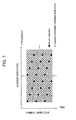
FIGs. 1A and 1B are explanatory diagrams about intercarrier interference; -
FIG. 2 is an explanatory diagram illustrating the combination of signals leaking into adjacent carriers inNon-Patent Document 1; -
FIG. 3 is an explanatory diagram illustrating intercarrier interference cancellation inPatent Document 1; -
FIG. 4 is a block diagram schematically showing structure of a receiving device according to a first embodiment; -
FIG. 5 is a diagram showing structure of a transmission signal in the first embodiment; -
FIG. 6 is a schematic diagram illustrating delay profile estimation using PN sequence correlation property in the first embodiment; -
FIG. 7 is a diagram showing structure of the transmission signal in the first embodiment; -
FIGs. 8A and 8B are diagrams illustrating an interpolation process in the first embodiment; -
FIG. 9 is a block diagram schematically showing structure of a leak-in coefficient calculation means in the first embodiment; -
FIG. 10 is a diagram showing a signal component leaking into an adjacent carrier on the right in the first embodiment; -
FIG. 11 is a diagram showing a signal component leaking into an adjacent carrier on the left in the first embodiment; -
FIG. 12 is a block diagram schematically showing structure of a receiving device according to a second embodiment; -
FIG. 13 is a diagram showing the arrangement of signal points of the transmission signal in the second embodiment; -
FIG. 14 is a diagram showing the signal points of transmission and reception in the second embodiment; -
FIGs. 15A and 15B are diagrams concerning a method of determining a weighting coefficient in the second embodiment; -
FIG. 16 is a block diagram schematically showing structure of a receiving device according to a third embodiment; -
FIG. 17 is a block diagram schematically showing structure of a receiving device according to a fourth embodiment; -
FIG. 18 is a block diagram schematically showing structure of a demodulation means in the fourth embodiment; -
FIG. 19 is a block diagram schematically showing structure of a Doppler shift correction means in the fourth embodiment; -
FIG. 20 is a block diagram schematically showing structure of a demodulation means in a fifth embodiment; -
FIG. 21 is a block diagram schematically showing an example of structure of a second leak-in coefficient calculation means shown inFIG. 20 ; -
FIG. 22 is a block diagram schematically showing structure of a demodulation means in a sixth embodiment; and -
FIG. 23 is a block diagram schematically showing an example of structure of an FFT window position detection means shown inFIG. 22 . - In order to describe an outline of a receiving device and a receiving method according to a first embodiment of the present invention, carriers of received signals are expressed by the following equations 1 (each of the equations is expressed as equation 1-1, equation 1-2, equation 1-3 and equation 1-4).


- In the equations, yn represents an n-th carrier of the received signal; xn represents an n-th carrier of a transmission signal; H is a matrix representing a transmission path, including elements of i rows and j columns (i j); hi,j represents a leak-in coefficient from a j-th carrier to an i-th carrier; and an on-diagonal element hi,i represents a transmission path property acting on the i-th carrier, where
n = 1, 2, ... , N
i = 1, 2, ..., N
j = 1, 2, ..., N. - From the
equation 1, an n-th subcarrier yn of the received signal is expressed byequation 2 below.
In theequation 2, a first term on a right side represents a signal component transmitted by the n-th carrier, and a second term on the right side represents interference components from adjacent carriers. - Furthermore, from the
equation 1, an n+1-th carrier yn+1 of the received signal is expressed byequation 3 below.
In theequation 3, a first term on a right side is a signal component leaking from a signal transmitted by the n-th carrier to the n+1-th carrier, and a second term on the right side represents the other interference components. - Similarly, an n-1-th carrier yn-1 of the received signal is expressed by
equation 4 below.
In theequation 4, a first term on a right side represents a signal component leaking from the signal xn transmitted by the n-th carrier to the n-1-th carrier, and a second term on the right side represents the other interference components. - The inter-carrier interference cancellation method described in
Patent Document 1 estimates the interference components represented by the second term on the right side of theequation 2, from the received signal, and eliminates the estimated interference components, thereby eliminating the leak-in components from the adjacent carriers. In contrast to this, the receiving device and the receiving method according to the first embodiment are characterized in that the second term on the right side of theequation 2, the second term on the right side of theequation 3, and the second term on the right side of theequation 4 are individually from the received signal, the estimated interference components are eliminated, and thereafter the signal components, the interference components of which have been eliminated, are combined. -
FIG. 4 is a block diagram schematically showing structure of the receiving device according to the first embodiment. As shown inFIG. 4 , the receiving device according to the first embodiment includes a transmission path estimation means 1 for estimating the transmission path property from a known signal included in the received signal, an FFT computation means 2 for transforming the received signal to a frequency domain, a correction means 3 for correcting distortion in the received signal, a leak-in coefficient calculation means 4 for calculating an inter-carrier interference leak-in coefficient, an interference component estimation means 5 for estimating an interference component included in each carrier, an adjacent-carrier interference component estimation means (1) 6 for estimating an interference component other than the signal component leaking into an adjacent carrier on the right, and an adjacent-carrier interference component estimation means (2) 7 for estimating an interference component other than the signal component leaking into an adjacent carrier on the left. The adjacent-carrier interference component estimation means (1) 6 and the adjacent-carrier interference component estimation means (2) 7 function as an unwanted component estimation means for estimating an unwanted component other than the signal component transmitted by the carrier to be demodulated among a plurality of carriers other than the carrier to be demodulated, on the basis of the signals output from the transmission path estimation means 1, the leak-in coefficient calculation means 4, and the correction means 3. The receiving device according to the first embodiment further includes a subtraction means (0) 8 for subtracting the interference component from each carrier of the received signal, a subtraction means (1) 9 for subtracting the interference component other than the signal component leaking from an adjacent carrier on the left of each carrier of the received signal, a subtraction means (2) 10 for subtracting the interference component other than the signal component leaking from an adjacent carrier on the right of each carrier of the received signal, and a combination means 11 for combining the signals output from the subtraction means (0) 8, the subtraction means (1) 9, and the subtraction means (2) 10. The unwanted component estimation means and a second subtraction means (subtraction means (1) 9 and subtraction means (2) 10) for subtracting the signal output from the unwanted component estimation means from the signal output from the FFT computation means 2 function as a signal component estimation means for estimating a desired signal component included in a plurality of carriers other than the carrier to be demodulated, on the basis of the signal of the frequency domain output from the FFT computation means 2, the signal of estimation result of the transmission path property output from the transmission path estimation means 1, the signal indicating the leak-in coefficient output from the leak-in coefficient calculation means 4, and the corrected signal of the frequency domain output from the correction means 3. - In the first embodiment, a description will be made as to a case where a signal transmitted in units of transmission symbols S1 including a significant symbol So generated from the transmission data with a PN sequence (pseudorandom sequence) added prior to it (
FIG. 5, FIG. 6 ) is received or a case where a signal obtained by frequency-multiplexing, in which a known pilot carrier is assigned to a plurality of given carriers among the carriers used to send the transmission data is received (FIG. 7 ,FIGs.8A and 8B ). - The transmission path estimation means 1 in
FIG. 4 estimates the transmission path property from a known signal. Estimation methods of the transmission path property are different depending on whether the known signal is a PN sequence or a pilot carrier. Next, each of the estimation methods will be described. - First, the method of estimating the transmission path property from the PN sequence will be described. It is generally known that the PN sequence has a strong correlation property. The transmission path estimation means 1 first calculates a correlation between the received signal and a known PN sequence prepared beforehand (in a storage means which is not shown in the drawings) in the receiver.
FIG. 6 shows a result of a correlation calculation in a transmission path of a two-ray ground reflection model. As shown inFIG. 6 , when the PN sequence included in a dominant wave agrees with the PN sequence prepared by the receiver, a correlation peak corresponding to the dominant wave is output; when the PN sequence included in the delayed wave agrees with the PN sequence prepared by the receiver, a correlation peak corresponding to the delayed wave is output. These correlation peaks are complex values representing amplitude and phase of the dominant wave and the delayed wave respectively. The transmission path estimation means 1 obtains the estimation result of the transmission path property acting on each carrier by transforming the results of correlation to the frequency domain. - Next, the method of estimating a transmission path property from the pilot carrier will be described. The transmission path estimation means 1 first transforms the received signal to the frequency domain, extracts a pilot carrier, and compares it with the pilot carrier prepared beforehand (in a storage means which is not shown in the drawings) by the receiver, thereby estimating the transmission path property acting on the pilot carrier. As shown in
FIGs. 8A and 8B , the transmission path properties acting on all the carriers are estimated by interpolating the transmission path property acting on the pilot carrier in a symbol direction and in a carrier direction. - Let the transmission path property estimated by either of the methods described above be

where n = 1, 2, ..., N. This
is an estimated value of the on-diagonal element hn,n of the matrix H in theequation 1. A diagonal matrix having
as an on-diagonal element is defined as given byequation 5 below.
- The FFT computation means 2 in
FIG. 4 obtains yn (n = 1, 2, ..., N) by transforming the received signal to the frequency domain. This yn is the n-th carrier of the received signal and is an n-th element of a vector y representing the received signal of theequation 1. - The correction means 3 in
FIG. 4 corrects distortion of the signal output from the FFT computation means 2 in accordance with the signal output from the transmission path estimation means 1. More specifically, the correction means 3 divides the n-th carrier yn,n of the received signal by an estimation result of the transmission path property
acting on the n-th carrier. Based on theequation 2, the result of the division is expressed byequation 6 given below.
- In this connection, it is assumed that the estimated value output from the transmission path estimation means 1 is correct. Then,

A first term on a right side of theequation 6 is the signal transmitted by the n-th carrier of the transmission signal, and a second term on the right side is an error component caused by leakage from the adjacent carriers. - The leak-in coefficient calculation means 4 in
FIG. 4 executes calculation that is similar to calculation in the method described inPatent Document 1. The leak-in coefficient calculation means 4 will be described briefly below. -
FIG. 9 is a block diagram schematically showing structure of the leak-in coefficient calculation means 4. As shown inFIG. 9 , the leak-in coefficient calculation means 4 includes a delay means 31 for delaying the signal output from the transmission path estimation means 1 by two symbol intervals, a difference calculation means 32 for calculating a difference in estimation results of transmission path among symbols, for each carrier, and a constant matrix multiplication means 33 for multiplying the results of calculation by the difference calculation means by a constant matrix. - The difference calculation means 32 in
FIG. 9 calculates a difference between signals having the same carrier numbers in different symbols. For example, let the transmission path property acting on the n-th carrier of the m+1-th symbol be
and the transmission path property acting on the n-th carrier of the m-1-th symbol be
Then, a result of the difference calculation is obtained by
In this connection, a matrix H having the calculated difference as a diagonal component is defined as given byequation 7 below.
- The constant matrix multiplication means 33 in
FIG. 9 multiplies H defined by theequation 7 by a constant matrix
expressed byequation 8 below.

- The result obtained by multiplying H of the
equation 7 by the constant matrix
of theequation 8 is expressed byequation 9 below.

- The element

of the matrix K given by theequation 9 in the i-th row and the j-th column (i j) becomes the estimated value of the element hi,j of the matrix H representing the transmission path property of theequation 1 in the i-th row and the j-th column (i j). The leak-in coefficient calculation means 4 inFIG. 4 calculates and outputs the matrix K expressed by theequation 9. - Now, if the leak-in coefficient calculation means 4 in
FIG. 4 considers just a component leaking into L adjacent carriers, the constant matrix can be simplified as given byequation 10 below.
Consequently, the amount of computation can be reduced. - Although the multiplication of the matrix given by the
equation 9 is needed to obtain the leak-in coefficient, as described above, the computation of theequation 9 means the multiplication of a fixed value L (I = -L to L) prepared beforehand by the receiver by
(n = 1, 2, ..., N) in each carrier, and the amount of computation is far smaller than the amount of computation of the inverse matrix inNon-Patent Document 1. - The interference component estimation means 5 in
FIG. 4 estimates the interference component included in each carrier on the basis of the signal output from the correction means 3 and the signal output from the leak-in coefficient calculation means 4. Letting the output of the correction means 3 given by theequation 6 be
The interference component estimation means 5 performs calculation as expressed byequation 11 below.
- The n-th element of the vector

in theequation 11 is expressed byequation 12 below.
The component expressed by theequation 12 indicates the total sum of the estimated values of the leak-in components from the adjacent carriers. - The subtraction means (0) 8 in
FIG. 4 obtains the signal expressed byequation 13 below by subtracting the estimated interference component cn expressed by theequation 12 from the n-th carrier yn of the received signal expressed by theequation 2.
- Here, the assumption that the estimation result of the leak-in coefficient and the correction result of the received signal are correct gives


This causes a second term on a right side of theequation 13 and a third term on the right side to cancel out each other, consequently eliminating the inter-carrier interference component. - The adjacent-carrier interference component estimation means 6 in
FIG. 4 will be described by defining the matrix as given by equation 14 below on the basis of theequations 
The element
in the i-th row and the j-th column in the equation 14 is the estimated value of the element hn,j of the matrix H representing the transmission path property defined by theequation 1 in the i-th row and the j-th column. - The adjacent-carrier interference component estimation means (1) 6 in
FIG. 4 first defines equation 15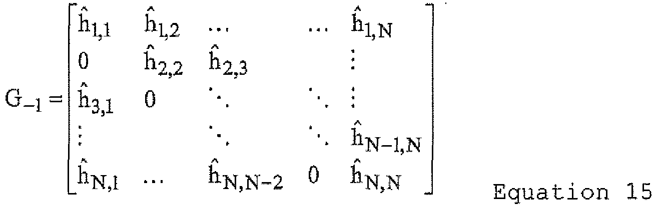
representing a matrix obtained by replacing an element of the i-th row and the i-1-th column of the matrix
Ĥ
given by the equation 14 by 0. - The vector
x̂
obtained by the correction means 3 is multiplied by this matrix, thereby obtaining equation 16 below.
- An n+1-th element of a vector

in the equation 16 is expressed by equation 17 below.
- The component expressed by the equation 17 is the sum of interference components other than the signal leaking from the n-th carrier to the n+1-th carrier, as shown in
FIG. 10 . - The subtraction means (1) 9 in
FIG. 4 obtains the signal expressed by equation 18 below
by subtracting the component expressed by the equation 17 from the n+1-th carrier yn+1 of the received signal expressed by theequation 3. - It is assumed here that the estimation result of the leak-in coefficient and the correction result of the received signal are correct. This provides


thereby causing the second term on the right side of the equation 18 and the third term on the right side to cancel out each other. Consequently, the signal component LO1 leaking from the n-th carrier to the n+1-th carrier can be extracted as shown inFIG. 10 . - Similarly, the adjacent-carrier interference component estimation means (2) 7 in
FIG. 4 first defines equation 19 below
which is the matrix obtained by replacing an element of the i-th row and the i+1-th column of the matrix
Ĥ
given by the equation 14 by 0. - The vector
x̂
obtained by the correction means 3 is multiplied by this matrix, thereby obtaining equation 20 below.
- An n-1-th element of a vector

in the equation 20 is expressed byequation 21 below.
- The component expressed by the
equation 21 is the sum of interference components other than the signal component LO2 leaking from the n-th carrier to the n-1-th carrier, as shown inFIG. 11 . - The subtraction means (2) 10 in
FIG. 4 obtains a signal expressed byequation 22 below
by subtracting the estimation result of the interference component expressed by theequation 21 from the n-1-th carrier of the received signal expressed by theequation 4. - It is assumed here that the estimation result of the leak-in coefficient and the correction result of the received signal are correct. Since this provides the following:


causing the second term and the third term of theequation 22 to cancel out each other. Consequently, the signal leaking from the n-th carrier to the n-1-th carrier can be extracted as shown inFIG. 11 . - The combining means 11 in
FIG. 4 combines the signals output from the subtraction means (0) 8, the subtraction means (1) 9, and the subtraction means (2) 10. Letting the signals output from the subtraction means (0) 8, the subtraction means (1) 9, and the subtraction means (2) 10 be
respectively, the result obtained by combining the signals is expressed byequation 23 below.
- The outputs from the subtraction means (0) 8, the subtraction means (1) 9, and the subtraction means (2) 10 are multiplied by the corresponding estimation result of the transmission path property and the complex conjugate of the estimation result of the leak-in coefficients

respectively as given by theequation 23, and then divided by
for normalization. - As described above, the receiving device and the receiving method according to the first embodiment can correct the Doppler shift and can improve the receiving sensitivity by extracting the individual components leaking into the adjacent carriers and combining them. Unlike
Non-Patent Document 1, this process does not require the inverse matrix computation, and consequently can correct the Doppler shift by a small amount of computation. - The
equation 11 in the first embodiment indicates that if accuracy of the corrected signal
x̂
is low, the inter-carrier interference estimation error becomes large, making it impossible to suppress the inter-carrier interference sufficiently. In a second embodiment, the inter-carrier interference estimation error is reduced by multiplying a signal having a low signal-to-noise power ratio by a small weighting coefficient. -
FIG. 12 is a block diagram schematically showing structure of a receiving device according to the second embodiment. InFIG. 12 , elements identical to or corresponding to the elements inFIG. 4 (first embodiment) will be denoted by the same reference numerals. The receiving device shown inFIG. 12 differs from the receiving device shown inFIG. 4 in that a weighting means 12 is included. The weighting means 12 will be described mainly. - A signal transmitted by carriers of a transmission signal in the second embodiment is a complex signal obtained by multi-value digital modulation. For example, transmission information is modulated by addressing four bits of transmission information to each of the sixteen signal points as shown in
FIG. 13 , and the receiving device receives the transmission signal with noise added. If a signal point A inFIG. 14 is sent, for example, the signal point of the signal output from the correction means 3 inFIG. 12 is affected by noise and becomes a point B inFIG. 14 . As shown inFIG. 14 , the receiving device generally makes grid like partitions each containing a signal point of the transmission signal at its center, detects the partition containing the signal point of the signal output from the correction means 3, and judges that the transmission information is sent at the signal point corresponding the partition. This is called a hard decision. - If the signal-to-noise power ratio is high, the signal point of the signal output from the correction means 3 is in the vicinity of the signal point of the transmission signal. As the signal-to-noise power ratio decreases, the signal point of the signal output from the correction means 3 separates from the signal point of the transmission signal. If the signal-to-noise power ratio is so low that the signal point crosses the boundary and enters an adjacent partition, an error occurs in restoration of the transmission bit.
- The weighting means 12 in
FIG. 12 determines a weighting coefficient based on the idea that the corrected signal point near the boundary has a low signal-to-noise power ratio and a low reliability. More specifically, as a distance L between a signal point of the transmission signal and a signal point of the signal output from the correction means 3 increases, a smaller weighting coefficient is given, as shown inFIG. 14 . -
FIGs. 15A and 15B show two examples of determining a weighting coefficient.FIG. 15A shows that the weighting coefficient gradually decreases if the distance between the signal point of the transmission signal and the signal point of the signal output from the correction means 3 exceeds a predetermined threshold L1.FIG. 15B shows that the weighting coefficient becomes 0 when the distance between the signal point of the transmission signal and the signal point of the signal output from the correction means 3 exceeds a predetermined threshold L2. - The weighting means 12 in
FIG. 12 multiplies the signal output from the correction means 3 by the weighting coefficient determined by the methods described above. The weighting coefficient may be multiplied after a hard decision is made on the signal output from the correction means 3. - As described above, the receiving device and the receiving method according to the second embodiment multiply the signal output from the correction means 3 by a weighting coefficient decreasing as the distance between the signal point of the transmission signal and the signal point of the signal output from the correction means 3 increases. This reduces the inter-carrier interference estimation error, thereby allowing the Doppler shift to be corrected accurately.
- As already described in the second embodiment, if accuracy of the corrected signal
x̂
is low, the inter-carrier interference estimation error becomes large, as can be understood from theequation 11 in the first embodiment, and consequently the inter-carrier interference cannot be suppressed sufficiently. In a receiving device and a receiving method according to a third embodiment, a signal output from the combining means 11 is fed back to reduce the inter-carrier interference estimation error. -
FIG. 16 is a block diagram schematically showing structure of the receiving device according to the third embodiment. InFIG. 16 , elements identical to or corresponding to the elements inFIG. 4 (first embodiment) will be denoted by the same reference numerals. The receiving device shown inFIG. 16 differs from the receiving device shown inFIG. 4 in that a switching means 13 is included. The switching means 13 will be described mainly. - In the third embodiment, inter-carrier interference included in the received signal is first suppressed and the result is output from the combining means 11, as described in the first embodiment. The switching means 13 in
FIG. 16 selects and outputs a signal input from the correction means 3. In the third embodiment, the signal output from the combining means 11 is fed back to the switching means 13. The switching means 13 selects and outputs the signal input from the combining means 11. On the basis of the signal output from the combining means 11, the inter-carrier interference is suppressed again, and the result is output from the combining means 11. - As described above, the receiving device and the receiving method according to the third embodiment improves the accuracy of
x̂
in theequation 11 by feeding the signal output from the combining means 11 back and suppressing inter-carrier interference repeatedly, and consequently can correct the Doppler shift more accurately. - In a fourth embodiment, Doppler shift correction in a diversity receiving device will be described, taking dual antenna diversity as an example.
-
FIG. 17 is a block diagram schematically showing structure of a receiving device according to the fourth embodiment. As shown inFIG. 17 , the receiving device according to the fourth embodiment includes demodulation means 21 and 22 for demodulating received signals, a first combining means 23 for combining signals output from the demodulation means 21 and 22, Doppler shift correction means 24 and 25 for compensating an effect of a Doppler shift included in the signals output from the demodulation means 21 and 22, and a second combining means 26 for combining signals output from the Doppler shift correction means 24 and 25. -
FIG. 18 is a block diagram schematically showing structure of the demodulation means 21 and 22 inFIG. 17 . As shown inFIG. 18 , the demodulation means 21 and 22 include an FFT computation means 2 and a transmission path estimation means 1 respectively. The FFT computation means 2 transforms the received signal to a frequency domain, and the transmission path estimation means 1 estimates the transmission path property from a known signal included in the received signal. These means are the same as those in the first embodiment. - The first combining means 23 in
FIG. 17 combines signals obtained by performing FFT of the received signal, on the basis of the estimation result of the transmission path property obtained by the demodulation means (1) 21 and the demodulation means (2) 22. Generally known combining methods include selection combining, equal gain combining, and maximal ratio combining. The combining methods will be described briefly. - In
FIG. 17 , let the result of FFT of the received signal output from the demodulation means (1) 21 be a1s + n1, let the estimation result of the transmission path property be a1', let the result of FFT of the received signal output from the demodulation means (2) 22 be a2s + n2, and let the estimation result of the transmission path property be a2', where s represents a sent signal point, a1 and a2 represent the transmission path property acting on the transmission signal s, and n1 and n2 represent noise. - Selection combining is a method of comparing |a1'| and |a2'| and selecting and correcting a larger signal. For example, if |a1'| > |a2'|, a signal as expressed by
equation 24 below
is output. - In equal gain combining, the signals output from the demodulation means (1) 21 and the demodulation means (2) 22 are corrected and then averaged out, as expressed by
equation 25 below.
- In maximal ratio combining, the signals output from the demodulation means (1) 21 and the demodulation means (2) 22 are multiplied by the complex conjugate of the signal output from the transmission path estimation means 1 as a weight, and the signals are summed up, as expressed by
equation 26 below.
- In
FIG. 17 , a signal combined by the combining method expressed by any of the equations 24 - 26 is input to the Doppler shift correction means (1) 24 and the Doppler shift correction means (2) 25.FIG. 19 is a block diagram schematically showing structure of the Doppler shift correction means (1) 24 and the Doppler shift correction means (2) 25. The means inFIG. 19 are the same as the corresponding means in the first embodiment (FIG. 4 ). The combined result input to the Doppler shift correction means (1) 24 and the Doppler shift correction means (2) 25 is used as
x̂
in theequation 11 described in the first embodiment. - The second combining means 26 in
FIG. 17 combines the signals output from the combining means included in the Doppler shift correction means (1) 24 and the Doppler shift correction means (2) 25. The second combining means 26 uses any of the selection combining, the equal gain combining, and the maximal ratio combining, for example, as its combining method. - Since the receiving device and the receiving method according to the fourth embodiment combine the signals output from a plurality of demodulation means and use the combined result as
x̂
in theequation 11, as described above, the inter-carrier interference estimation error is reduced, and consequently the effect of the Doppler shift can be corrected more accurately. - In a fifth embodiment, a receiving device and a receiving method that can correct a Doppler shift accurately even if an FFT window position changes.
-
FIG. 20 is a block diagram schematically showing structure of the receiving device according to the fifth embodiment. InFIG. 20 , elements identical to or corresponding to the elements inFIG. 4 used in the description of the first embodiment, are denoted by the same reference numerals. Specifically,elements FIG. 20 operate in a similar way to the elements having the identical reference numerals inFIG. 4 . The receiving device according to the fifth embodiment differs from the receiving device according to the first embodiment in that a second leak-in coefficient calculation means 100 for receiving FFT window position information and the output from the transmission path estimation means 1, instead of the leak-in coefficient calculation means 4 in the first embodiment. - Next, the operation of the receiving device according to the fifth embodiment and the receiving method will be described in detail. The second leak-in coefficient calculation means 100 receives an output (a signal of estimation result of the transmission path property) of the transmission path estimation means 1 and FFT window position information, corrects a phase shift in the output signal of the transmission path estimation means 1, caused by a change in the FFT window position, on the basis of the FFT window position information given from the outside, calculates the inter-carrier interference leak-in coefficient, and outputs a signal indicating the leak-in coefficient.
-
FIG. 21 is a block diagram schematically showing an example of structure of the second leak-in coefficient calculation means 100 shown inFIG. 20 . As shown inFIG. 21 , the second leak-in coefficient calculation means 100 includes a delay means (1) 101a for outputting the output from the transmission path estimation means 1 after a delay of a single symbol interval and a delay means (2) 101b for outputting the output of the delay means (1) 101a after another delay of a single symbol interval. The second leak-in coefficient calculation means 100 also includes a phase correction means (1) 102a, a phase correction means (2) 102b, a difference calculation means 32, and a constant matrix multiplication means 33. The difference calculation means 32 and the constant matrix multiplication means 33 are the same as those described in the first embodiment (FIG. 9 ). - The delay means (1) 101a delays the output of the transmission path estimation means 1 by a single symbol interval, and the delay means (2) 101b delays the output of the delay means (1) 101a further by a single symbol interval. The phase correction means (1) 102a gives a phase rotation to the output of the transmission path estimation means 1 in accordance with the input FFT window position information. The FFT window position information is an input signal supplied from the outside and expresses the difference of the FFT window position in the FFT computation means 2 from the reference position or the amount of difference from the preceding symbol. The phase correction means (1) 102a gives the output of the transmission path estimation means 1 a reverse phase rotation from the phase rotation of the output of the transmission path estimation means 1 resulting from the difference in the FFT window position. Accordingly, the output of the phase correction means (1) 102a is a signal with the effect of the difference in FFT window position eliminated. The phase correction means (2) 102b corrects the phase of the output of the phase correction means (2) 102b in accordance with the FFT window position information corresponding to the output of the delay means (2) 101b. The signals of which phase is corrected by the phase correction means (1) 102a and the phase correction means (2) 102b respectively are converted to a leak-in coefficient by the difference calculation means 32 and the constant matrix multiplication means 33.
- The second leak-in coefficient calculation means 100 is configured to calculate the leak-in coefficient from the signal of which phase rotation resulting from the FFT window shift is corrected and is not confined to the structure shown in
FIG. 21 . For example, although the output of the transmission path estimation means 1 is directly input to the delay means (1) 101a inFIG. 21 , the output of the transmission path estimation means 1 may be corrected by a phase correction means (not shown in the drawings), and then the corrected signal may be input to the delay means (1) 101a. In this case, the phase correction means (1) 102a and the phase correction means (2) 102b can be omitted. - The second leak-in coefficient calculation means 100 may also include three or more delay means and may calculate a leak-in coefficient by using signals of estimation results of the transmission path property of three or more symbols. The configuration can be used if each signal of estimation result of the transmission path property is phase-corrected. The number of delay means may also be only one, and the leak-in coefficient may be calculated by using the signal of estimation result of the transmission path property of a single symbol. Accordingly, the second leak-in coefficient calculation means 100 can be configured by at least one delay means for outputting the output of the transmission path estimation means 1 after a delay of a single symbol interval, at least one phase correction means for giving the output of the transmission path estimation means 1 a reverse phase rotation from the phase rotation of the output of the transmission path estimation means 1 resulting from the difference from the preceding symbol or the difference from the reference FFT window position obtained as the FFT window position information, a difference calculation means 32 for calculating the difference between the signal of estimation result of the transmission path property of which phase has been corrected by the phase correction means and the signal of estimation result of the transmission path property which has been delayed by the delay means in units of symbols and has been phase-corrected by the phase correction means, and a constant matrix multiplication means 33 for multiplying the output of the difference calculation means 32 by a constant matrix.
- According to the receiving device and the receiving method according to the fifth embodiment, even if the FFT window position is changed in the FFT computation from the outside, the leak-in coefficient is calculated from the signal in which phase rotation caused by the change in FFT window position has been corrected, so that the Doppler shift can be corrected for independently of the FFT window position, and a mobile reception capability can be improved.
- In the fifth embodiment, the description has been made as to a case where the FFT window position information is known and input from the outside. A receiving device and a receiving method according to a sixth embodiment, however, can correct the Doppler shift accurately even if the FFT window position information is not known.
-
FIG. 22 is a block diagram schematically showing structure of the receiving device according to the sixth embodiment. InFIG. 22 , elements identical to or corresponding to the elements inFIG. 20 used to describe the fifth embodiment, are denoted by the same reference numerals. Specifically,elements FIG. 22 operate in a similar way to the elements having the corresponding reference numerals inFIG. 20 . The receiving device according to the sixth embodiment differs from the receiving device according to the fifth embodiment in that an FFT window position detection means 103 is provided and that the FFT window position information detected by the FFT window position detection means 103 is input to the second leak-in coefficient calculation means 100. - The operation of the receiving device and the receiving method according to the sixth embodiment will next be described. The FFT window position detection means 103 generates FFT window position information on the basis of an output (a signal of estimation result of the transmission path property) of the transmission path estimation means 1 and outputs the information to the second leak-in coefficient calculation means 100.
-
FIG. 23 is a block diagram schematically showing an example of structure of the FFT window position detection means 103 shown inFIG. 22 . As shown inFIG. 23 , the FFT window position detection means 103 includes an inverse Fourier transformation means 104, a level calculation means 105, and an FFT window position determination means 106. - The inverse Fourier transformation means 104 performs an inverse Fourier transform on the output of the transmission path estimation means 1 at given number of points (data count) and outputs the results. The output of the inverse Fourier transformation means 104 is input to the level calculation means 105. The level calculation means 105 calculates a square value of an absolute value of a complex signal, which is the output of the inverse Fourier transformation means 104, or an absolute value of a complex signal. The output of the level calculation means 105 represents a delay profile of the transmission path or its equivalent signal. The FFT window position determination means 106 determines the FFT window position from a difference between a point number (index) of the reference inverse Fourier transform and the index of the inverse Fourier transform which gives the maximum value of the output of the level calculation means 105, and outputs it as the FFT window position information.
- The difference in delay profile information among symbols, obtained as the output of the level calculation means 105, represents a change in the FFT window position, and detection of the difference between the maximum value and the reference value of the output of the level calculation means 105, is not always necessary. For example, a change in index of the inverse Fourier transform that gives the maximum value of the output of the level calculation means 105 may be detected as the FFT window position information. Alternatively, the FFT window position may be detected from the difference between the recently detected output signal of the level calculation means 105 and a newly detected output signal of the level calculation means 105, instead of the maximum value of the output of the level calculation means 105.
- As described above, the receiving device and the receiving method according to the sixth embodiment is configured to calculate the leak-in coefficient from the signal obtained by correcting the phase rotation caused by the change in the FFT window position even if the FFT window position is changed from the outside in the FFT computation. Accordingly, the Doppler shift can be corrected for independently of the effect of the FFT window position, and a mobile reception capability can be improved consequently.
- 1 transmission path estimation means; 2 FFT computation means; 3 correction means; 4 leak-in coefficient calculation means; 5 interference component estimation means; 6 adjacent-carrier interference component estimation means (1); 7 adjacent-carrier interference component estimation means (2); 8 subtraction means (0); 9 subtraction means (1); 10 subtraction means (2); 11 combining means; 12 weighting means; 13 switching means; 21 demodulation means (1); 22 demodulation means (2); 23 first combining means; 24 Doppler shift correction means (1); 25 Doppler shift correction means (2); 26 second combining means; 31 delay means; 32 difference calculation means; 33 constant matrix multiplication means; 100 second leak-in coefficient calculation means; 101a delay means (1); 101b delay means (2); 102a phase correction means (1); 102b phase correction means (2); 103 FFT window position detection means; 104 inverse Fourier transformation means; 105 level calculation means; 106 FFT window position determination means.
Claims (14)
- A receiving device for receiving a signal obtained by inserting a known signal into a signal obtained by frequency-multiplexing a plurality of carriers used to send transmission data, at given intervals on the time axis or a signal obtained by frequency-multiplexing by assigning a known pilot carrier to a plurality of given carriers among carriers used to send transmission data, the receiving device comprising:a transmission path estimation means (1) for estimating a transmission path property from the known signal or the known pilot carrier included in the received signal, thereby outputting a signal of estimation result of the transmission path property;an FFT computation means (2) for transforming the received signal to a frequency domain, thereby outputting a signal of the frequency domain;a correction means (3) for correcting distortion of the signal of the frequency domain output from the FFT computation means (2) on the basis of the signal of estimation result of the transmission path property output from the transmission path estimation means (1);a leak-in coefficient calculation means (4) for calculating an inter-carrier interference leak-in coefficient on the basis of the signal of estimation result of the transmission path property output from the transmission path estimation means (1), thereby outputting a signal indicating the leak-in coefficient;an interference component estimation means (5) for estimating an interference component included in the carrier (n) to be demodulated, on the basis of the signal indicating the leak-in coefficient output from the leak-in coefficient calculation means (4) and the corrected signal of the frequency domain output from the correction means (3);a first subtraction means (8) for obtaining a desired first signal component included in the carrier (n) to be demodulated, by subtracting the interference component estimated by the interference component estimation means (5) from the signal of the frequency domain output from the FFT computation means (1);a signal component estimation means (6, 7, 9, 10) for estimating a desired second signal component included in a plurality of carriers other than the carrier (n) to be demodulated, on the basis of the signal of the frequency domain output from the FFT computation means (2), the signal of estimation result of the transmission path property output from the transmission path estimation means (1), the signal indicating the leak-in coefficient output from the leak-in coefficient calculation means (4), and the corrected signal of the frequency domain output from the correction means (3), the signal component estimation means (6, 7, 9, 10) being arranged to estimate the second signal component by subtracting, from each of a first carrier (n+1) and a second carrier (n-1) in the signal output from the FFT computation means (2) that are each adjacent to the carrier (n) to be demodulated, a sum of interference components other than signals leaking from the carrier (n) to be demodulated to the respective first or second carrier (n+1; n-1); anda combining means (11) for combining the first signal component output from the first subtraction means (8) and the second signal component output from the signal component estimation means (6, 7, 9, 10).
- The receiving device according to Claim 1, wherein the signal component estimation means includes:an unwanted component estimation means (6, 7) for estimating the interference components other than signals leaking from the carrier (n) that is to be demodulated to the first and second carriers (n+1, n-1), on the basis of the signal of estimation result of the transmission path property output from the transmission path estimation means (1), the signal indicating the leak-in coefficient output from the leak-in coefficient calculation means (4), and the corrected signal of the frequency domain output from the correction means (3); anda second subtraction means (9, 10) for subtracting, from each of the first and second carrier (n+1, n-1) in the signal output from the FFT computation means (2), the sum of interference components other than signals leaking from the carrier (n) that is to be demodulated to the respective first or second carrier (n+1; n-1).
- The receiving device according to Claim 1 or 2, further comprising a weighting means (12) for determining a weighting coefficient of each carrier on the basis of the corrected signal of the frequency domain of each carrier output from the correction means (3) and multiplying the corrected signal of the frequency domain by the weighting coefficient so as to weight the corrected signal of the frequency domain input to the interference component estimation means and the signal component estimation means.
- The receiving device according to Claim 1 or 2, further comprising a switching means (13) for receiving the corrected signal of the frequency domain output from the correction means (3) and the signal output from the combining means (11), thereby outputting either the corrected signal of the frequency domain output from the correction means (3) or the signal output from the combining means (11) selectively to the signal component estimation means (6, 7, 9, 10).
- A receiving device for receiving a signal obtained by inserting a known signal into a signal obtained by frequency-multiplexing a plurality of carriers used to send transmission data, at given intervals on the time axis, or a signal obtained by frequency-multiplexing by assigning a known pilot carrier to a plurality of given carriers among carriers used to send transmission data, by using a plurality of antennas, the receiving device comprising:a plurality of demodulation means (21, 22) corresponding respectively to the plurality of antennas;a plurality of Doppler shift correction means (24, 25) corresponding respectively to the plurality of demodulation means (21, 22);a first combining means (23) for combining signals output from the plurality of demodulation means (21, 22); anda second combining means (26) for combining signals output from the plurality of Doppler shift correction means (24, 25);each of the plurality of demodulation means (21, 22) including:a transmission path estimation means (1) for estimating a transmission path property from the known signal or the pilot carrier included in the received signal, thereby outputting a signal of estimation result of the transmission path property; andan FFT computation means (2) for transforming the received signal to a frequency domain, thereby outputting a signal of the frequency domain;the first combining means (23) combining the signals of the frequency domain output from the FFT computation means (2), on the basis of the signal of estimation result of the transmission path property output from the transmission path estimation means (1) included in each of the plurality of demodulation means (21, 22);each of the plurality of Doppler shift correction means (24, 25) including:a leak-in coefficient calculation means (4) for calculating an inter-carrier interference leak-in coefficient on the basis of the signal of estimation result of the transmission path property output from the transmission path estimation means (1) included in the corresponding demodulation means of the plurality of demodulation means (21, 22), thereby outputting a signal indicating the leak-in coefficient;an interference component estimation means (5) for estimating an interference component included in the carrier (n) to be demodulated, on the basis of the signal indicating the leak-in coefficient output from the leak-in coefficient calculation means (4) and the signal output from the first combining means (23);a subtraction means (8) for obtaining a desired signal component included in the carrier (n) to be demodulated, by subtracting the interference component signal estimated by the interference component estimation means (5) from the signal of the frequency domain output from the FFT computation means (2) included in the corresponding demodulation means;a signal component estimation means (6, 7, 9, 10) for estimating a desired second signal component included in a plurality of carriers other than the carrier (n) to be demodulated, on the basis of the signal of the frequency domain output from the FFT computation means (2) included in the corresponding demodulation means, the signal of estimation result of the transmission path property output from the transmission path estimation means (1), the signal indicating the leak-in coefficient output from the leak-in coefficient calculation means (4), and the signal output from the first combining means (23), the signal component estimation means (6, 7, 9, 10) being arranged to estimate the second signal component by subtracting, from each of a first carrier (n+1) and a second carrier (n-1) in the signal output from the FFT computation means (2) that are each adjacent to the carrier (n) to be demodulated, a sum of interference components other than signals leaking from the carrier (n) to be demodulated to the respective first or second carrier (n+1; n-1); anda third combining means (11) for combining the signal output from the subtraction means (8) and the signal output from the signal component estimation means (6, 7, 9, 10);the second combining means (26) being arranged to combine signals output from the third combining means (11) included in the plurality of Doppler shift correction means (24, 25), on the basis of signals of estimation results of the transmission path property output from the transmission path estimation means (1) included in each of the plurality of demodulation means (21, 22).
- A receiving method of receiving a signal obtained by inserting a known signal into a signal obtained by frequency-multiplexing a plurality of carriers used to send transmission data, at given intervals on the time axis or a signal obtained by frequency-multiplexing by assigning a known pilot carrier to a plurality of given carriers among carriers used to send transmission data, the receiving method comprising:a transmission path estimation step of estimating a transmission path property from the known signal or the pilot carrier included in the received signal, thereby outputting a signal of estimation result of the transmission path property;an FFT computation step of transforming the received signal to a frequency domain, thereby outputting a signal of the frequency domain;a correction step of correcting distortion of the signal of the frequency domain generated in the FFT computation step, on the basis of the signal of estimation result of the transmission path property output from the transmission path estimation step;a leak-in coefficient calculation step of calculating an inter-carrier interference leak-in coefficient on the basis of the signal of estimation result of the transmission path property generated in the transmission path estimation step, thereby outputting a signal indicating the leak-in coefficient;an interference component estimation step of estimating an interference component included in the carrier (n) to be demodulated, on the basis of the signal indicating the leak-in coefficient generated in the leak-in coefficient calculation step, and the corrected signal of the frequency domain generated in the correction step;a first subtraction step of obtaining a desired first signal component included in the carrier (n) to be demodulated, by subtracting the interference component estimated in the interference component estimation step from the signal of the frequency domain generated in the FFT computation step;a signal component estimation step of estimating a desired second signal component included in a plurality of carriers other than the carrier (n) to be demodulated, on the basis of the signal of the frequency domain output from the FFT computation step, the signal of estimation result of the transmission path property generated in the transmission path estimation step, the signal indicating the leak-in coefficient generated in the leak-in coefficient calculation step, and the corrected signal of the frequency domain generated in the correction step, the second signal component being estimated by subtracting, from each of a first carrier (n+1) and a second carrier (n-1) in the signal output from the FFT computation means (2) that are each adjacent to the carrier (n) to be demodulated, a sum of interference components other than signals leaking from the carrier (n) to be demodulated to the respective first or second carrier (n+1; n-1); anda combining step of generating a combined signal by combining the first signal component generated in the first subtraction step and the second signal component generated in the signal component estimation step.
- The receiving method according to Claim 6, wherein the signal component estimation step comprises:an unwanted component estimation step of estimating the interference components other than signals leaking from the carrier (n) that is to be demodulated to the first and second carriers (n+1, n-1), on the basis of the signal of estimation result of the transmission path property generated in the transmission path estimation step, the signal indicating the leak-in coefficient generated in the leak-in coefficient calculation step, and the corrected signal of the frequency domain generated in the correction step; anda second subtraction step of subtracting, from each of the first and second carrier (n+1, n-1) in the signal output from the FFT computation means (2), the sum of interference components other than signals leaking from the carrier (n) that is to be demodulated to the respective first or second carrier (n+1; n-1).
- The receiving method according to Claim 6 or 7, further comprising a weighting step of determining a weighting coefficient of each carrier on the basis of the corrected signal of the frequency domain of each carrier generated in the correction step, and multiplying the corrected signal of the frequency domain by the weighting coefficient so as to weight the corrected signal of the frequency domain used in the interference component estimation step and the signal component estimation step.
- The receiving method according to Claim 6 or 7, further comprising:generating a second estimate of the interference component, on the basis of the signal indicating the leak-in coefficient generated in the leak-in coefficient calculation step and the combined signal generated in the combining step;obtaining a second estimate of the first signal component by subtracting the second estimate of the interference component from the signal of the frequency domain generated in the FFT computation step;generating a second estimate of the second signal component on the basis of the signal of the frequency domain output from the FFT computation step, the signal of estimation result of the transmission path property generated in the transmission path estimation step, the signal indicating the leak-in coefficient generated in the leak-in coefficient calculation step, and the combined signal generated in the combining step; andcombining the second estimate of the first signal component and the second estimate for the second signal.
- A receiving method of receiving a signal obtained by inserting a known signal into a signal obtained by frequency-multiplexing a plurality of carriers used to send transmission data, at given intervals on the time axis, or a signal obtained by frequency-multiplexing by assigning a known pilot carrier to a plurality of given carriers among carriers used to send transmission data, by using a plurality of antennas, the receiving method comprising:a demodulation step of generating a plurality of demodulation signals corresponding respectively to the plurality of antennas;a Doppler shift correction step of performing a Doppler shift correction on the plurality of demodulation signals;a first combining step of combining a plurality of demodulation signals generated in the demodulation step; anda second combining step of combining signals generated in the Doppler shift correction step;the demodulation step including:a transmission path estimation step of estimating a transmission path property from the known signal or the pilot carrier included in the received signal, thereby outputting a signal of estimation result of the transmission path property; andan FFT computation step of transforming the received signal to a frequency domain, thereby outputting a signal of the frequency domain;the first combining step including:a step of combining the signals of the frequency domain generated in the FFT computation step, on the basis of the signal generated in the transmission path estimation step;the Doppler shift correction step including:a leak-in coefficient calculation step of calculating an inter-carrier interference leak-in coefficient on the basis of the signal generated in the transmission path estimation step, thereby outputting a signal indicating the leak-in coefficient;an interference component estimation step of estimating an interference component included in the carrier (n) to be demodulated, on the basis of the signal indicating the leak-in coefficient, generated in the leak-in coefficient calculation step, and the signal output from the first combining step;a subtraction step of obtaining a desired signal component included in the carrier (n) to be demodulated, by subtracting the interference component signal estimated in the interference component estimation step from the signal of the frequency domain generated in the FFT computation step;a signal component estimation step of estimating a desired second signal component included in a plurality of carriers other than the carrier (n) to be demodulated, on the basis of the signal of the frequency domain generated in the FFT computation step, the signal of the frequency domain generated in the transmission path estimation step, the signal indicating the leak-in coefficient, generated in the leak-in coefficient calculation step, and the signal generated in the first combining step, the signal component estimation means (6, 7, 9, 10) being arranged to estimate the second signal component by subtracting, from each of a first carrier (n+1) and a second carrier (n-1) in the signal output from the FFT computation means (2) that are each adjacent to the carrier (n) to be demodulated, a sum of interference components other than signals leaking from the carrier (n) to be demodulated to the respective first or second carrier (n+1; n-1); anda third combining step of combining signals output from the subtraction step and the signal component estimation step;the second combining step including a step of combining signals generated in the third combining step, on the basis of the signal of estimation result of the transmission path property generated in the transmission path estimation step.
- A receiving device for receiving a signal obtained by inserting a known signal into a signal obtained by frequency-multiplexing a plurality of carriers used to send transmission data, at given intervals on the time axis, or a signal obtained by frequency-multiplexing by assigning a known pilot carrier to a plurality of given carriers among carriers used to send transmission data, the receiving device comprising:a transmission path estimation means (1) for estimating a transmission path property from the known signal or the pilot carrier included in the received signal, thereby outputting a signal of estimation result of the transmission path property;an FFT computation means (2) for transforming the received signal to a frequency domain, thereby outputting a signal of the frequency domain;a correction means (3) for correcting distortion of the signal of the frequency domain output from the FFT computation means (2), on the basis of the signal of estimation result of the transmission path property output from the transmission path estimation means (1);a leak-in coefficient calculation means (100) for calculating an inter-carrier interference leak-in coefficient on the basis of the signal of estimation result of the transmission path property output from the transmission path estimation means (1) and FFT window position information in the FFT computation means (2), thereby outputting a signal indicating the leak-in coefficient;an interference component estimation means (5) for estimating an interference component included in the carrier (n) to be demodulated, on the basis of the signal indicating the leak-in coefficient output from the leak-in coefficient calculation means (100), and the corrected signal of the frequency domain output from the correction means (3);a first subtraction means (8) for obtaining a desired first signal component included in the carrier (n) to be demodulated, by subtracting the interference component estimated by the interference component estimation means (5) from the signal of the frequency domain output from the FFT computation means (2);a signal component estimation means (6, 7, 9, 10) for estimating a desired second signal component included in a plurality of carriers other than the carrier (n) to be demodulated, on the basis of the signal of the frequency domain output from the FFT computation means (2), the signal of estimation result of the transmission path property output from the transmission path estimation means (1), the signal indicating the leak-in coefficient output from the leak-in coefficient calculation means (100), and the corrected signal of the frequency domain output from the correction means (3), the signal component estimation means (6, 7, 9, 10) being arranged to estimate the second signal component by subtracting, from each of a first carrier (n+1) and a second carrier (n-1) in the signal output from the FFT computation means (2) that are each adjacent to the carrier (n) to be demodulated, a sum of interference components other than signals leaking from the carrier (n) to be demodulated to the respective first or second carrier (n+1; n-1); anda combining means (11) for combining the first signal component output from the first subtraction means (8) and the second signal component output from the signal component estimation means (6, 7, 9, 10).
- A receiving device for receiving a signal obtained by inserting a known signal into a signal obtained by frequency-multiplexing a plurality of carriers used to send transmission data, at given intervals on the time axis, or a signal obtained by frequency-multiplexing by assigning a known pilot carrier to a plurality of given carriers among carriers used to send transmission data, the receiving device comprising:a transmission path estimation means (1) for estimating a transmission path property from the known signal or the pilot carrier included in the received signal, thereby outputting a signal of estimation result of the transmission path property;an FFT computation means (2) for transforming the received signal to a frequency domain, thereby outputting a signal of the frequency domain;a correction means (3) for correcting distortion of the signal of the frequency domain output from the FFT computation means (2), on the basis of the signal of estimation result of the transmission path property output from the transmission path estimation means (1);an FFT window position detection means (103) for detecting an FFT window position in the FFT computation means (2), on the basis of the signal of estimation result of the transmission path property output from the transmission path estimation means (1), thereby outputting FFT window position information;a leak-in coefficient calculation means (100) for calculating an inter-carrier interference leak-in coefficient, on the basis of the signal of estimation result of the transmission path property output from the transmission path estimation means (1) and the FFT window position information, thereby outputting a signal indicating the leak-in coefficient;an interference component estimation means (5) for estimating an interference component included in the carrier (n) to be demodulated, on the basis of the signal indicating the leak-in coefficient output from the leak-in coefficient calculation means (100) and the corrected signal of the frequency domain output from the correction means (3);a first subtraction means (8) for obtaining a desired first signal component included in the carrier (n) to be demodulated, by subtracting the interference component estimated by the interference component estimation means (5) from the signal of the frequency domain output from the FFT computation means (2);a signal component estimation means (6, 7, 9, 10) for estimating a desired second signal component included in a plurality of carriers other than the carrier (n) to be demodulated, on the basis of the signal of the frequency domain output from the FFT computation means (2), the signal of estimation result of the transmission path property output from the transmission path estimation means (1), the signal indicating the leak-in coefficient output from the leak-in coefficient calculation means (100), and the corrected signal of the frequency domain output from the correction means (3), the signal component estimation means (6, 7, 9, 10) being arranged to estimate the second signal component by subtracting, from each of a first carrier (n+1) and a second carrier (n-1) in the signal output from the FFT computation means (2) that are each adjacent to the carrier (n) to be demodulated, a sum of interference components other than signals leaking from the carrier (n) to be demodulated to the respective first or second carrier (n+1; n-1); anda combining means (11) for combining the first signal component output from the first subtraction means (8) and the second signal component output from the signal component estimation means (6, 7, 9, 10).
- The receiving device according to Claim 11 or 12, wherein the leak-in coefficient calculation means (100) includes:at least one delay means (101a, 101b) for outputting the output of the transmission path estimation means (1) after a delay of a single symbol interval;at least one phase correction means (102a, 102b) for giving the output of the transmission path estimation means (1) a reverse phase rotation from the phase rotation of the output of the transmission path estimation means, resulting from the difference from the preceding symbol or the difference of the FFT window position obtained as the FFT window position information from the reference position;a difference calculation means (32) for calculating the difference between the signal of estimation result of the transmission path property of which phase has been corrected by the phase correction means (102a, 102b) and the signal of estimation result of the transmission path property which has been delayed by the delay means (101a, 101b) in units of symbols and has been phase-corrected by the phase correction means; anda constant matrix multiplication means (33) for multiplying the output of the difference calculation means (32) by a constant matrix.
- The receiving device according to Claim 12, wherein the FFT window position detection means (103) includes:an inverse Fourier transformation means (104) for performing an inverse Fourier transform on the output of the transmission path estimation means (1);a level calculation means (105) for calculating the square value of the absolute value of the complex signal, which is the output of the inverse Fourier transformation means (104), or the absolute value of the complex signal; anda window position determination means (106) for detecting an FFT window position from a change in the output of the level calculation means (105) or the index of the inverse Fourier transform that gives the maximum value of the output of the level calculation means (105).
Applications Claiming Priority (4)
| Application Number | Priority Date | Filing Date | Title |
|---|---|---|---|
| JP2009276584 | 2009-12-04 | ||
| PCT/JP2010/000677 WO2011067866A1 (en) | 2009-12-04 | 2010-02-04 | Receiver apparatus and reception method |
| JP2010249824 | 2010-11-08 | ||
| PCT/JP2010/006908 WO2011067907A1 (en) | 2009-12-04 | 2010-11-26 | Receiver device and receiving method |
Publications (3)
| Publication Number | Publication Date |
|---|---|
| EP2509240A1 EP2509240A1 (en) | 2012-10-10 |
| EP2509240A4 EP2509240A4 (en) | 2014-01-01 |
| EP2509240B1 true EP2509240B1 (en) | 2015-11-04 |
Family
ID=44114770
Family Applications (1)
| Application Number | Title | Priority Date | Filing Date |
|---|---|---|---|
| EP10834363.3A Active EP2509240B1 (en) | 2009-12-04 | 2010-11-26 | Receiver devices and receiving methods |
Country Status (4)
| Country | Link |
|---|---|
| EP (1) | EP2509240B1 (en) |
| JP (1) | JP5047391B2 (en) |
| CN (1) | CN102648591B (en) |
| WO (1) | WO2011067907A1 (en) |
Families Citing this family (4)
| Publication number | Priority date | Publication date | Assignee | Title |
|---|---|---|---|---|
| CN103973321A (en) * | 2013-02-06 | 2014-08-06 | 中国电子科技集团公司第十研究所 | Method for increasing flexibility of multi-tone frequency modulated signal receiver |
| US11240773B2 (en) | 2018-12-07 | 2022-02-01 | Google Llc | Managing doppler and framing impacts in networks |
| KR20210101957A (en) | 2020-02-11 | 2021-08-19 | 삼성전자주식회사 | Method and apparatus for detecting velocity of object in radar system |
| CN119916294B (en) * | 2025-01-21 | 2026-01-27 | 哈尔滨工程大学 | A correlation direction finding system based on FPGA |
Family Cites Families (6)
| Publication number | Priority date | Publication date | Assignee | Title |
|---|---|---|---|---|
| JP4189477B2 (en) * | 2003-01-10 | 2008-12-03 | 国立大学法人東京工業大学 | OFDM (Orthogonal Frequency Division Multiplexing) Adaptive Equalization Reception System and Receiver |
| US7706428B2 (en) * | 2005-04-21 | 2010-04-27 | Telefonaktiebolaget L M Ericsson (Publ) | Low complexity inter-carrier interference cancellation |
| EP1940062B1 (en) | 2005-10-21 | 2016-09-07 | Panasonic Intellectual Property Management Co., Ltd. | Inter-carrier interference removal device and reception device using the same |
| CN101542952B (en) * | 2007-01-12 | 2013-11-27 | 松下电器产业株式会社 | OFDM reception device, OFDM reception integrated circuit and OFDM reception method |
| KR101359628B1 (en) * | 2007-10-25 | 2014-02-06 | 삼성전자주식회사 | Method for Inter-carrier interference cancellation and equalization method, apparatus, and OFDM receiver using the method |
| JP2009141740A (en) * | 2007-12-07 | 2009-06-25 | Panasonic Corp | ICI amount estimating apparatus, estimating method, and receiving apparatus using the same |
-
2010
- 2010-11-26 EP EP10834363.3A patent/EP2509240B1/en active Active
- 2010-11-26 CN CN201080053312.9A patent/CN102648591B/en not_active Expired - Fee Related
- 2010-11-26 JP JP2011544186A patent/JP5047391B2/en active Active
- 2010-11-26 WO PCT/JP2010/006908 patent/WO2011067907A1/en not_active Ceased
Also Published As
| Publication number | Publication date |
|---|---|
| WO2011067907A1 (en) | 2011-06-09 |
| EP2509240A1 (en) | 2012-10-10 |
| JPWO2011067907A1 (en) | 2013-04-18 |
| CN102648591A (en) | 2012-08-22 |
| JP5047391B2 (en) | 2012-10-10 |
| EP2509240A4 (en) | 2014-01-01 |
| CN102648591B (en) | 2015-01-14 |
Similar Documents
| Publication | Publication Date | Title |
|---|---|---|
| JP4938679B2 (en) | Inter-carrier interference canceling apparatus and receiving apparatus using the same | |
| JP3724501B1 (en) | Demodulator, diversity receiver and demodulation method | |
| US8699448B2 (en) | Method and arrangement for improved interference rejection combining | |
| US8275053B2 (en) | Apparatus and method of estimating channel based on channel delay spread in mobile communication system | |
| US20090196166A1 (en) | Receiver and frequency information estimating method | |
| JP6140565B2 (en) | Diversity receiver | |
| EP3588885A1 (en) | Wireless communication system | |
| JP2008118411A (en) | Radio receiver | |
| JP5308438B2 (en) | Interference estimation method for orthogonal pilot pattern | |
| JP5282042B2 (en) | Method and apparatus for impairment correlation evaluation in multi-antenna receiver | |
| EP2509240A1 (en) | Receiver device and receiving method | |
| JP4829849B2 (en) | OFDM signal combining receiver and repeater | |
| JP4789678B2 (en) | OFDM receiving method and OFDM receiving apparatus | |
| JP4115466B2 (en) | OFDM receiver | |
| JP5795466B2 (en) | Receiver | |
| JP4688761B2 (en) | OFDM signal combining receiver and repeater | |
| JP4719102B2 (en) | Propagation path estimation device and path diversity reception device | |
| JP5566223B2 (en) | Diversity receiving apparatus and diversity receiving method | |
| JP5473751B2 (en) | OFDM signal combining receiver | |
| JP4658835B2 (en) | OFDM receiver | |
| WO2011067866A1 (en) | Receiver apparatus and reception method | |
| JP4714636B2 (en) | Mobile receiver and method of operating the same | |
| JP2010272977A (en) | Wireless receiver | |
| JP4725356B2 (en) | OFDM communication device |
Legal Events
| Date | Code | Title | Description |
|---|---|---|---|
| PUAI | Public reference made under article 153(3) epc to a published international application that has entered the european phase |
Free format text: ORIGINAL CODE: 0009012 |
|
| 17P | Request for examination filed |
Effective date: 20120314 |
|
| AK | Designated contracting states |
Kind code of ref document: A1 Designated state(s): AL AT BE BG CH CY CZ DE DK EE ES FI FR GB GR HR HU IE IS IT LI LT LU LV MC MK MT NL NO PL PT RO RS SE SI SK SM TR |
|
| DAX | Request for extension of the european patent (deleted) | ||
| A4 | Supplementary search report drawn up and despatched |
Effective date: 20131203 |
|
| RIC1 | Information provided on ipc code assigned before grant |
Ipc: H04L 27/26 20060101ALI20131127BHEP Ipc: H04J 11/00 20060101AFI20131127BHEP Ipc: H04L 25/03 20060101ALI20131127BHEP |
|
| 17Q | First examination report despatched |
Effective date: 20140410 |
|
| GRAP | Despatch of communication of intention to grant a patent |
Free format text: ORIGINAL CODE: EPIDOSNIGR1 |
|
| INTG | Intention to grant announced |
Effective date: 20140908 |
|
| GRAP | Despatch of communication of intention to grant a patent |
Free format text: ORIGINAL CODE: EPIDOSNIGR1 |
|
| INTG | Intention to grant announced |
Effective date: 20150521 |
|
| GRAS | Grant fee paid |
Free format text: ORIGINAL CODE: EPIDOSNIGR3 |
|
| GRAA | (expected) grant |
Free format text: ORIGINAL CODE: 0009210 |
|
| AK | Designated contracting states |
Kind code of ref document: B1 Designated state(s): AL AT BE BG CH CY CZ DE DK EE ES FI FR GB GR HR HU IE IS IT LI LT LU LV MC MK MT NL NO PL PT RO RS SE SI SK SM TR |
|
| REG | Reference to a national code |
Ref country code: GB Ref legal event code: FG4D |
|
| REG | Reference to a national code |
Ref country code: CH Ref legal event code: EP |
|
| REG | Reference to a national code |
Ref country code: AT Ref legal event code: REF Ref document number: 759818 Country of ref document: AT Kind code of ref document: T Effective date: 20151115 |
|
| REG | Reference to a national code |
Ref country code: IE Ref legal event code: FG4D |
|
| REG | Reference to a national code |
Ref country code: DE Ref legal event code: R096 Ref document number: 602010028867 Country of ref document: DE |
|
| REG | Reference to a national code |
Ref country code: NL Ref legal event code: MP Effective date: 20151104 |
|
| REG | Reference to a national code |
Ref country code: LT Ref legal event code: MG4D |
|
| REG | Reference to a national code |
Ref country code: AT Ref legal event code: MK05 Ref document number: 759818 Country of ref document: AT Kind code of ref document: T Effective date: 20151104 |
|
| PG25 | Lapsed in a contracting state [announced via postgrant information from national office to epo] |
Ref country code: ES Free format text: LAPSE BECAUSE OF FAILURE TO SUBMIT A TRANSLATION OF THE DESCRIPTION OR TO PAY THE FEE WITHIN THE PRESCRIBED TIME-LIMIT Effective date: 20151104 Ref country code: NL Free format text: LAPSE BECAUSE OF FAILURE TO SUBMIT A TRANSLATION OF THE DESCRIPTION OR TO PAY THE FEE WITHIN THE PRESCRIBED TIME-LIMIT Effective date: 20151104 Ref country code: IS Free format text: LAPSE BECAUSE OF FAILURE TO SUBMIT A TRANSLATION OF THE DESCRIPTION OR TO PAY THE FEE WITHIN THE PRESCRIBED TIME-LIMIT Effective date: 20160304 Ref country code: HR Free format text: LAPSE BECAUSE OF FAILURE TO SUBMIT A TRANSLATION OF THE DESCRIPTION OR TO PAY THE FEE WITHIN THE PRESCRIBED TIME-LIMIT Effective date: 20151104 Ref country code: NO Free format text: LAPSE BECAUSE OF FAILURE TO SUBMIT A TRANSLATION OF THE DESCRIPTION OR TO PAY THE FEE WITHIN THE PRESCRIBED TIME-LIMIT Effective date: 20160204 Ref country code: LT Free format text: LAPSE BECAUSE OF FAILURE TO SUBMIT A TRANSLATION OF THE DESCRIPTION OR TO PAY THE FEE WITHIN THE PRESCRIBED TIME-LIMIT Effective date: 20151104 Ref country code: IT Free format text: LAPSE BECAUSE OF FAILURE TO SUBMIT A TRANSLATION OF THE DESCRIPTION OR TO PAY THE FEE WITHIN THE PRESCRIBED TIME-LIMIT Effective date: 20151104 |
|
| PG25 | Lapsed in a contracting state [announced via postgrant information from national office to epo] |
Ref country code: SE Free format text: LAPSE BECAUSE OF FAILURE TO SUBMIT A TRANSLATION OF THE DESCRIPTION OR TO PAY THE FEE WITHIN THE PRESCRIBED TIME-LIMIT Effective date: 20151104 Ref country code: FI Free format text: LAPSE BECAUSE OF FAILURE TO SUBMIT A TRANSLATION OF THE DESCRIPTION OR TO PAY THE FEE WITHIN THE PRESCRIBED TIME-LIMIT Effective date: 20151104 Ref country code: PL Free format text: LAPSE BECAUSE OF FAILURE TO SUBMIT A TRANSLATION OF THE DESCRIPTION OR TO PAY THE FEE WITHIN THE PRESCRIBED TIME-LIMIT Effective date: 20151104 Ref country code: RS Free format text: LAPSE BECAUSE OF FAILURE TO SUBMIT A TRANSLATION OF THE DESCRIPTION OR TO PAY THE FEE WITHIN THE PRESCRIBED TIME-LIMIT Effective date: 20151104 Ref country code: AT Free format text: LAPSE BECAUSE OF FAILURE TO SUBMIT A TRANSLATION OF THE DESCRIPTION OR TO PAY THE FEE WITHIN THE PRESCRIBED TIME-LIMIT Effective date: 20151104 Ref country code: BE Free format text: LAPSE BECAUSE OF NON-PAYMENT OF DUE FEES Effective date: 20151130 Ref country code: PT Free format text: LAPSE BECAUSE OF FAILURE TO SUBMIT A TRANSLATION OF THE DESCRIPTION OR TO PAY THE FEE WITHIN THE PRESCRIBED TIME-LIMIT Effective date: 20160304 Ref country code: LV Free format text: LAPSE BECAUSE OF FAILURE TO SUBMIT A TRANSLATION OF THE DESCRIPTION OR TO PAY THE FEE WITHIN THE PRESCRIBED TIME-LIMIT Effective date: 20151104 Ref country code: GR Free format text: LAPSE BECAUSE OF FAILURE TO SUBMIT A TRANSLATION OF THE DESCRIPTION OR TO PAY THE FEE WITHIN THE PRESCRIBED TIME-LIMIT Effective date: 20160205 |
|
| REG | Reference to a national code |
Ref country code: CH Ref legal event code: PL |
|
| PG25 | Lapsed in a contracting state [announced via postgrant information from national office to epo] |
Ref country code: LI Free format text: LAPSE BECAUSE OF NON-PAYMENT OF DUE FEES Effective date: 20151130 Ref country code: CZ Free format text: LAPSE BECAUSE OF FAILURE TO SUBMIT A TRANSLATION OF THE DESCRIPTION OR TO PAY THE FEE WITHIN THE PRESCRIBED TIME-LIMIT Effective date: 20151104 Ref country code: CH Free format text: LAPSE BECAUSE OF NON-PAYMENT OF DUE FEES Effective date: 20151130 |
|
| REG | Reference to a national code |
Ref country code: DE Ref legal event code: R097 Ref document number: 602010028867 Country of ref document: DE |
|
| REG | Reference to a national code |
Ref country code: IE Ref legal event code: MM4A |
|
| PG25 | Lapsed in a contracting state [announced via postgrant information from national office to epo] |
Ref country code: SM Free format text: LAPSE BECAUSE OF FAILURE TO SUBMIT A TRANSLATION OF THE DESCRIPTION OR TO PAY THE FEE WITHIN THE PRESCRIBED TIME-LIMIT Effective date: 20151104 Ref country code: EE Free format text: LAPSE BECAUSE OF FAILURE TO SUBMIT A TRANSLATION OF THE DESCRIPTION OR TO PAY THE FEE WITHIN THE PRESCRIBED TIME-LIMIT Effective date: 20151104 Ref country code: SK Free format text: LAPSE BECAUSE OF FAILURE TO SUBMIT A TRANSLATION OF THE DESCRIPTION OR TO PAY THE FEE WITHIN THE PRESCRIBED TIME-LIMIT Effective date: 20151104 Ref country code: DK Free format text: LAPSE BECAUSE OF FAILURE TO SUBMIT A TRANSLATION OF THE DESCRIPTION OR TO PAY THE FEE WITHIN THE PRESCRIBED TIME-LIMIT Effective date: 20151104 Ref country code: RO Free format text: LAPSE BECAUSE OF FAILURE TO SUBMIT A TRANSLATION OF THE DESCRIPTION OR TO PAY THE FEE WITHIN THE PRESCRIBED TIME-LIMIT Effective date: 20151104 |
|
| PLBE | No opposition filed within time limit |
Free format text: ORIGINAL CODE: 0009261 |
|
| STAA | Information on the status of an ep patent application or granted ep patent |
Free format text: STATUS: NO OPPOSITION FILED WITHIN TIME LIMIT |
|
| PG25 | Lapsed in a contracting state [announced via postgrant information from national office to epo] |
Ref country code: MC Free format text: LAPSE BECAUSE OF FAILURE TO SUBMIT A TRANSLATION OF THE DESCRIPTION OR TO PAY THE FEE WITHIN THE PRESCRIBED TIME-LIMIT Effective date: 20151104 |
|
| 26N | No opposition filed |
Effective date: 20160805 |
|
| GBPC | Gb: european patent ceased through non-payment of renewal fee |
Effective date: 20160204 |
|
| PG25 | Lapsed in a contracting state [announced via postgrant information from national office to epo] |
Ref country code: IE Free format text: LAPSE BECAUSE OF NON-PAYMENT OF DUE FEES Effective date: 20151126 |
|
| REG | Reference to a national code |
Ref country code: FR Ref legal event code: ST Effective date: 20161003 |
|
| PG25 | Lapsed in a contracting state [announced via postgrant information from national office to epo] |
Ref country code: SI Free format text: LAPSE BECAUSE OF FAILURE TO SUBMIT A TRANSLATION OF THE DESCRIPTION OR TO PAY THE FEE WITHIN THE PRESCRIBED TIME-LIMIT Effective date: 20151104 Ref country code: FR Free format text: LAPSE BECAUSE OF NON-PAYMENT OF DUE FEES Effective date: 20160104 |
|
| PG25 | Lapsed in a contracting state [announced via postgrant information from national office to epo] |
Ref country code: BE Free format text: LAPSE BECAUSE OF FAILURE TO SUBMIT A TRANSLATION OF THE DESCRIPTION OR TO PAY THE FEE WITHIN THE PRESCRIBED TIME-LIMIT Effective date: 20151104 |
|
| PG25 | Lapsed in a contracting state [announced via postgrant information from national office to epo] |
Ref country code: GB Free format text: LAPSE BECAUSE OF NON-PAYMENT OF DUE FEES Effective date: 20160204 |
|
| PG25 | Lapsed in a contracting state [announced via postgrant information from national office to epo] |
Ref country code: HU Free format text: LAPSE BECAUSE OF FAILURE TO SUBMIT A TRANSLATION OF THE DESCRIPTION OR TO PAY THE FEE WITHIN THE PRESCRIBED TIME-LIMIT; INVALID AB INITIO Effective date: 20101126 Ref country code: BG Free format text: LAPSE BECAUSE OF FAILURE TO SUBMIT A TRANSLATION OF THE DESCRIPTION OR TO PAY THE FEE WITHIN THE PRESCRIBED TIME-LIMIT Effective date: 20151104 |
|
| PG25 | Lapsed in a contracting state [announced via postgrant information from national office to epo] |
Ref country code: CY Free format text: LAPSE BECAUSE OF FAILURE TO SUBMIT A TRANSLATION OF THE DESCRIPTION OR TO PAY THE FEE WITHIN THE PRESCRIBED TIME-LIMIT Effective date: 20151104 |
|
| PG25 | Lapsed in a contracting state [announced via postgrant information from national office to epo] |
Ref country code: MT Free format text: LAPSE BECAUSE OF FAILURE TO SUBMIT A TRANSLATION OF THE DESCRIPTION OR TO PAY THE FEE WITHIN THE PRESCRIBED TIME-LIMIT Effective date: 20151104 |
|
| PG25 | Lapsed in a contracting state [announced via postgrant information from national office to epo] |
Ref country code: LU Free format text: LAPSE BECAUSE OF NON-PAYMENT OF DUE FEES Effective date: 20151126 |
|
| REG | Reference to a national code |
Ref country code: DE Ref legal event code: R084 Ref document number: 602010028867 Country of ref document: DE |
|
| PG25 | Lapsed in a contracting state [announced via postgrant information from national office to epo] |
Ref country code: TR Free format text: LAPSE BECAUSE OF FAILURE TO SUBMIT A TRANSLATION OF THE DESCRIPTION OR TO PAY THE FEE WITHIN THE PRESCRIBED TIME-LIMIT Effective date: 20151104 Ref country code: MK Free format text: LAPSE BECAUSE OF FAILURE TO SUBMIT A TRANSLATION OF THE DESCRIPTION OR TO PAY THE FEE WITHIN THE PRESCRIBED TIME-LIMIT Effective date: 20151104 |
|
| PG25 | Lapsed in a contracting state [announced via postgrant information from national office to epo] |
Ref country code: AL Free format text: LAPSE BECAUSE OF FAILURE TO SUBMIT A TRANSLATION OF THE DESCRIPTION OR TO PAY THE FEE WITHIN THE PRESCRIBED TIME-LIMIT Effective date: 20151104 |
|
| P01 | Opt-out of the competence of the unified patent court (upc) registered |
Effective date: 20230512 |
|
| REG | Reference to a national code |
Ref country code: DE Ref legal event code: R081 Ref document number: 602010028867 Country of ref document: DE Owner name: MITSUBISHI ELECTRIC MOBILITY CORPORATION, JP Free format text: FORMER OWNER: MITSUBISHI ELECTRIC CORP., TOKYO, JP |
|
| PGFP | Annual fee paid to national office [announced via postgrant information from national office to epo] |
Ref country code: DE Payment date: 20250930 Year of fee payment: 16 |