EP2508778A2 - Gear wheel and gear-drive unit - Google Patents
Gear wheel and gear-drive unit Download PDFInfo
- Publication number
- EP2508778A2 EP2508778A2 EP12153408A EP12153408A EP2508778A2 EP 2508778 A2 EP2508778 A2 EP 2508778A2 EP 12153408 A EP12153408 A EP 12153408A EP 12153408 A EP12153408 A EP 12153408A EP 2508778 A2 EP2508778 A2 EP 2508778A2
- Authority
- EP
- European Patent Office
- Prior art keywords
- gear
- region
- lubricant
- groove
- tooth
- Prior art date
- Legal status (The legal status is an assumption and is not a legal conclusion. Google has not performed a legal analysis and makes no representation as to the accuracy of the status listed.)
- Granted
Links
- 239000000314 lubricant Substances 0.000 claims abstract description 41
- 230000005540 biological transmission Effects 0.000 claims description 19
- 239000004033 plastic Substances 0.000 claims description 7
- 238000001746 injection moulding Methods 0.000 claims description 6
- 229930040373 Paraformaldehyde Natural products 0.000 claims description 5
- 230000009471 action Effects 0.000 claims description 5
- 229920006324 polyoxymethylene Polymers 0.000 claims description 5
- 238000002347 injection Methods 0.000 claims description 3
- 239000007924 injection Substances 0.000 claims description 3
- 238000000034 method Methods 0.000 claims description 2
- -1 polyoxymethylene Polymers 0.000 claims description 2
- 230000008569 process Effects 0.000 claims description 2
- 210000004746 tooth root Anatomy 0.000 claims 1
- 239000004519 grease Substances 0.000 description 7
- 238000004519 manufacturing process Methods 0.000 description 6
- 230000007704 transition Effects 0.000 description 3
- 230000015572 biosynthetic process Effects 0.000 description 2
- 238000006073 displacement reaction Methods 0.000 description 2
- 230000000694 effects Effects 0.000 description 2
- 238000005461 lubrication Methods 0.000 description 2
- 239000000463 material Substances 0.000 description 2
- 238000002844 melting Methods 0.000 description 2
- 230000008018 melting Effects 0.000 description 2
- 238000007493 shaping process Methods 0.000 description 2
- 239000004696 Poly ether ether ketone Substances 0.000 description 1
- JUPQTSLXMOCDHR-UHFFFAOYSA-N benzene-1,4-diol;bis(4-fluorophenyl)methanone Chemical compound OC1=CC=C(O)C=C1.C1=CC(F)=CC=C1C(=O)C1=CC=C(F)C=C1 JUPQTSLXMOCDHR-UHFFFAOYSA-N 0.000 description 1
- 230000008859 change Effects 0.000 description 1
- 230000002950 deficient Effects 0.000 description 1
- 238000011161 development Methods 0.000 description 1
- 230000018109 developmental process Effects 0.000 description 1
- 230000017525 heat dissipation Effects 0.000 description 1
- 239000002184 metal Substances 0.000 description 1
- 229920002530 polyetherether ketone Polymers 0.000 description 1
- 229920000642 polymer Polymers 0.000 description 1
- 239000002861 polymer material Substances 0.000 description 1
- 230000009467 reduction Effects 0.000 description 1
Images

Classifications
-
- F—MECHANICAL ENGINEERING; LIGHTING; HEATING; WEAPONS; BLASTING
- F16—ENGINEERING ELEMENTS AND UNITS; GENERAL MEASURES FOR PRODUCING AND MAINTAINING EFFECTIVE FUNCTIONING OF MACHINES OR INSTALLATIONS; THERMAL INSULATION IN GENERAL
- F16H—GEARING
- F16H57/00—General details of gearing
- F16H57/04—Features relating to lubrication or cooling or heating
- F16H57/042—Guidance of lubricant
- F16H57/043—Guidance of lubricant within rotary parts, e.g. axial channels or radial openings in shafts
- F16H57/0431—Means for guiding lubricant directly onto a tooth surface or to foot areas of a gear, e.g. by holes or grooves in a tooth flank
-
- F—MECHANICAL ENGINEERING; LIGHTING; HEATING; WEAPONS; BLASTING
- F16—ENGINEERING ELEMENTS AND UNITS; GENERAL MEASURES FOR PRODUCING AND MAINTAINING EFFECTIVE FUNCTIONING OF MACHINES OR INSTALLATIONS; THERMAL INSULATION IN GENERAL
- F16H—GEARING
- F16H55/00—Elements with teeth or friction surfaces for conveying motion; Worms, pulleys or sheaves for gearing mechanisms
- F16H55/02—Toothed members; Worms
- F16H55/06—Use of materials; Use of treatments of toothed members or worms to affect their intrinsic material properties
- F16H2055/065—Moulded gears, e.g. inserts therefor
-
- F—MECHANICAL ENGINEERING; LIGHTING; HEATING; WEAPONS; BLASTING
- F16—ENGINEERING ELEMENTS AND UNITS; GENERAL MEASURES FOR PRODUCING AND MAINTAINING EFFECTIVE FUNCTIONING OF MACHINES OR INSTALLATIONS; THERMAL INSULATION IN GENERAL
- F16H—GEARING
- F16H57/00—General details of gearing
- F16H57/04—Features relating to lubrication or cooling or heating
- F16H57/0463—Grease lubrication; Drop-feed lubrication
- F16H57/0464—Grease lubrication
-
- F—MECHANICAL ENGINEERING; LIGHTING; HEATING; WEAPONS; BLASTING
- F16—ENGINEERING ELEMENTS AND UNITS; GENERAL MEASURES FOR PRODUCING AND MAINTAINING EFFECTIVE FUNCTIONING OF MACHINES OR INSTALLATIONS; THERMAL INSULATION IN GENERAL
- F16H—GEARING
- F16H57/00—General details of gearing
- F16H57/04—Features relating to lubrication or cooling or heating
- F16H57/048—Type of gearings to be lubricated, cooled or heated
- F16H57/0493—Gearings with spur or bevel gears
Definitions
- the invention relates to a gear according to the preamble of claim 1. Furthermore, the invention relates to a transmission drive unit using a gear according to the invention.
- a gear according to the preamble of claim 1 is already well known and is used in particular as part of a transmission drive unit in motor vehicles, for example as Wegver thoroughlysantrieb, window lift drive, windscreen wiper drive or the like.
- the speed of the drive motor is reduced while increasing the torque by means of coupled to an electric drive motor transmission, for example, to adjust a seat or a window in the vehicle.
- the transmission has at least one gear, which consists in particular of plastic, wherein the teeth are in operative connection with a cooperating with the gear, a counter-toothing having counter-element.
- the contact surface between the teeth of the gear and the counter teeth on the counter element is exposed to wear over the life of the drive unit. Therefore, it is known in the art to supply the gearbox of the transmission within a housing in assembly with a grease reservoir, e.g. is applied in the region of the side surfaces of the gear in the form of a grease or lubricant.
- the disadvantage here is that the grease pushed out of the contact area with increasing duration of the transmission drive unit to the side, but also thrown off. It is therefore possible, especially if the amount of rubbing fat deposits is relatively small, that it can lead to deficient lubrication conditions during operation. This lack of lubrication leads to a strong friction increase, which in turn leads to a reduced power output and increased wear of the gear. Furthermore, the increased friction power can lead to increased heat dissipation and melting or softening of the gear wheel, which usually consists of polymer material, which in the worst case can lead to a gearbox failure. When installing the gearbox drive unit, it is attempted to bring the grease as close as possible to the friction point. This is usually done by placing the grease on the tooth flanks on a side surface of the gear between the axis of rotation of the gear and the teeth.
- the invention has the object, a gear according to the preamble of claim 1 such that a supply of a friction-critical area on the gear from the radial intermediate region between the axis of rotation of the gear and the area of the teeth as simple as possible and at the same time effective way is ensured.
- This object is achieved in a gear with the features of claim 1 according to the invention in that on the tooth flank surface is formed at least one longitudinal groove for supplying the lubricant in the direction of the friction region. By means of this at least one longitudinal groove, the displacement of lubricant from the region of the friction surface is at least inhibited.
- the at least one longitudinal groove of at least one side surface of the gear in particular from the region of the tooth flank edge of the tooth , goes out.
- the at least one longitudinal groove extends to the friction surface, the friction surface itself
- at least substantially groove-free is formed. Due to the groove-free design of the friction surface in this case, in particular, a high hydraulic load capacity of the tooth flank of the tooth is made possible.
- the load capacity of the teeth can be increased if the friction surface has a lower roughness than the tooth root area of the tooth flank surface.
- the Zahnfuß Scheme is formed groove-free.
- a symmetrical or uniform supply of the friction surface with lubricant at the same time good functionality (carrying capacity) of the gear is achieved if at least one longitudinal groove emanates from both side surfaces of the gear, when the longitudinal grooves are formed approximately the same length, and if the length of the longitudinal grooves, which emanates from the respective side surface, based on the gear width, between 30% and 70%, preferably 45% to 55% of the gear width.
- longitudinal grooves In a further constructive embodiment of the longitudinal grooves, these have been found to be particularly advantageous if they have a width and depth between 5 .mu.m and 50 .mu.m, in particular 20 .mu.m, and if several longitudinal grooves in the presence of these are preferably arranged parallel to one another with a spacing of in particular about 20 .mu.m.
- the at least one longitudinal groove in the region of the tooth is additionally supplied with lubricant by a depot arranged outside the tooth. It is structurally provided that in a radial intermediate region between the axis of rotation and the teeth at least one depot for lubricant for additional supply of the friction surfaces of the teeth is arranged, wherein the intermediate region has at least one recess for forming the depot, and wherein between the recess for the depot and the area of the teeth on a surface of at least one of the side surfaces of the gear at least one lubricant guide, in particular in the form of a Zulakerille is formed, which connects the recess or the depot with the region of the teeth.
- the feed groove is formed in the region of at least one continuous, in particular a flat side surface of the toothed wheel. This results in a particularly simple flow of the lubricant from the depot in the direction of the region of the teeth.
- the feed groove starting from the recess for the depot, has a substantially directed to the rotation axis first portion which merges into a curved second portion, wherein the second portion at the level of the friction surface ends at a tooth flank edge.
- the transition from the side surface into the longitudinal groove for the lubricant as gently as possible, that is done without abrupt change of direction.
- the transition region is formed rounded from the ZuGermanrille in the longitudinal groove at the tooth flank edge.
- a gear according to the invention can be produced particularly easily with the additional depot and the longitudinal grooves if it consists of plastic and is designed as an injection molded part, wherein the at least one longitudinal groove and / or the recess for the depot during the injection process by a corresponding configuration of the injection molding tool is trained.
- the Recess for the depot at the level of the side surface in the region not connected to the feed groove is formed with at least one sharp-edged edge and / or the side surface in the area not connected to the feed groove with a relatively smooth surface.
- a preferred embodiment provides that the at least one longitudinal groove and possibly the Zuzhourille is provided with measures to form a capillary action for the lubricant in the direction of the friction surface. As a result, a targeted direction of the movement of the lubricant toward the friction surface can be generated.
- the invention also includes a transmission drive unit, in particular a window lift drive, a seat adjustment drive, a windshield wiper drive or the like with a drive motor and one with the drive motor coupled transmission, wherein the transmission has at least one inventive gear.
- a gear drive unit tends over the lifetime considered to a low wear or it is possible to realize the gear drive unit in reduced size or with lower production costs with the same functionality.
- the gear drive unit 100 serves in particular as a window lift drive, seat adjustment drive, windshield wiper drive or the like in a motor vehicle.
- the gear drive unit 100 has a drive motor 101 designed as an electric motor, which is flanged to a side surface of a gear housing 102.
- a not shown in the figures gear is arranged, which reduces a relatively high speed of the drive motor 101 while increasing the torque and thus a corresponding rotational movement of an output shaft 103 of the transmission drive unit 100 generated.
- the output shaft 103 is in turn mechanically connected at least indirectly to the object to be moved, for example a seat or a window pane.
- an inventive gear 10 is shown, which is used as part of the mentioned transmission in the transmission drive unit 100.
- the gear 10 is in particular made of plastic and is produced by injection molding.
- POM polyoxymethylene
- the toothed wheel 10 preferably has a multiplicity of teeth 1 on its outer circumference, which form a straight toothing in the exemplary embodiment.
- the teeth 1 form a helical toothing.
- the teeth 1 of the gear 10 cooperate with a counter-toothing of a counter-element, not shown, for example, connected to the drive motor 101 driving screw together.
- the area in which a tooth 1 meshes with the corresponding counter teeth in the Fig. 3 designated as friction surface 11.
- the friction surface 11 is in the in the Fig. 3 illustrated embodiment disposed approximately in the central region of a tooth 1 of the gear 10.
- the gear 10 has in its longitudinal axis a bore 12 for supporting the gear 10, e.g. in a stub axle, which is arranged in the transmission housing 102.
- the gear 10 is rotatably disposed in the transmission drive unit 100, so that the bore 12 at the same time forms the axis of rotation of the gear 10.
- the gear 10 in the region of the preferably flat side surfaces 13, 14 a plurality of recesses 15,18, during the manufacture of the gear 10 are formed or produced by a corresponding shaping or design of the injection molding tool.
- the depots 16 are separated by a radially circumferential intermediate web 17 of the radially inner recesses 18.
- the gear 10 has a plurality of depots 16 and first recesses 15, which are arranged distributed at equal angular intervals on the gear 10.
- feed grooves 20 are formed, which connect the region of the depots 16 with the radially outer region 21, in which the teeth 1 are arranged.
- the gear 10 preferably has a number of feed grooves 20 such that at least those tooth flank surfaces 22 are arranged in operative connection with the feed grooves 20, which have corresponding friction surfaces 11 or cooperate with the counter element mentioned.
- the gear 10 preferably has a number of feed grooves 20 such that at least those tooth flank surfaces 22 are arranged in operative connection with the feed grooves 20, which have corresponding friction surfaces 11 or cooperate with the counter element mentioned.
- the feed grooves 20 each consist of a rectilinearly formed in the embodiment first portion 23, which merges in the direction of the region 21 in a bent portion 24.
- the bent portion 24 in turn opens in the region 21 of the tooth 1 at a tooth flank edge 29 at the level of approximately the friction surface 11 (FIG. Figure 3 ).
- the straight section 23, which extends from the side of the depot 16 facing away from the tooth 1 from the edge of the recess 15, is oriented towards the bore 12, the bent section 24 preferably has the largest possible radius of curvature r.
- Such a design of the feed grooves 20 enables, in particular, the shortest possible transport path for the lubricant from the respective depot 16 in the direction of or the associated teeth 1. It is also important that the transition from the side surfaces 13, 14 to the tooth flank surfaces 22 in the region of the tooth flank edges 29 via preferably rounded tooth flank edge portions 25 as gently as possible, as in the Fig. 3 is shown.
- the edges 26, 27, the recesses 15 and the depots 16 in the region of the side surface 13, 14 limit, as sharp as possible or are formed with the smallest possible radius of curvature.
- the radius of curvature is to be chosen as small as possible for manufacturing reasons, taking into account the production costs.
- the side surfaces 13, 14 or areas in which no transport of lubricant should take place to be provided with the lowest possible roughness.
- the feed grooves 20 open in the region of a tooth 1 on the tooth flank delimiting tooth flank edge 29 in height of the friction surface 11. From the tooth flank edge 29 and the tooth flank edge portion 25 parallel to the tooth 1 aligned longitudinal grooves 30, wherein it is particularly preferably provided in that corresponding longitudinal grooves 30 emanate from both side surfaces 13, 14 of the toothed wheel 10. These longitudinal grooves 30 extend up to the friction surface 11, wherein the friction surface 11 itself, however, has no longitudinal grooves 30.
- the length I of the longitudinal grooves 30, which emanate from both side surfaces 13, 14 of the gear 10, is preferably formed approximately the same length and is about a quarter of the total gear width B. In particular, it is provided that the length I of each of both side surfaces 13th , 14 outgoing longitudinal grooves 30 together, based on the gear width B, between 30% and 70%, preferably 45% to 55% of the gear width B is.
- the longitudinal grooves 30 are preferably equipped, like the feed grooves 20, with an additional capillary action in the direction of the friction surface 11. This is again on the DE 10 2009 000 210 A1 the applicant referenced in which such measures are disclosed.
- the longitudinal grooves 30 form another depot for the lubricant, since the lubricant always moves in the direction of the friction surface 11 when there lubricant is consumed.
- the longitudinal grooves 30 and the tooth flank edge portions 25, as well as the feed grooves 20, are preferably already taken into account during the production of the gearwheel 10 or produced by a corresponding shaping of the injection molding tool.
- the longitudinal grooves 30 have a width b and a depth t of between 5 .mu.m and 50 .mu.m, in particular 20 .mu.m.
- the distance a in the presence of a plurality of longitudinal grooves 30 is preferably about 20 microns.
- the tooth root region 32 of a tooth 1 has no longitudinal grooves 30 and preferably a greater roughness, e.g. R27 has as the friction surface 11, which has, for example, a roughness of R21.
- the gear wheel 10 according to the invention as described above or the gear drive unit 100 can be modified or modified in many different ways, without departing from the spirit of the invention.
- This consists in the provision or the formation of at least one longitudinal groove 30 in the region of the tooth 1.
- the gear 10 may not be formed of plastic, but of metal.
- the longitudinal grooves 30 are formed as extending over the entire width B of the tooth 1 longitudinal grooves 30, or only spaced start from the tooth flank edge 29 and extend for example even into the region of the friction surface 11 , In particular, if the load capacity of the teeth 1 is not critical for the application.
Landscapes
- Engineering & Computer Science (AREA)
- General Engineering & Computer Science (AREA)
- Mechanical Engineering (AREA)
- Gears, Cams (AREA)
- General Details Of Gearings (AREA)
Abstract
Description
Die Erfindung betrifft ein Zahnrad nach dem Oberbegriff des Anspruchs 1. Ferner betrifft die Erfindung eine Getriebe-Antriebseinheit unter Verwendung eines erfindungsgemäßen Zahnrades.The invention relates to a gear according to the preamble of
Ein Zahnrad nach dem Oberbegriff des Anspruchs 1 ist bereits allgemein bekannt und wird insbesondere als Bestandteil einer Getriebe-Antriebseinheit in Kraftfahrzeugen, beispielsweise als Sitzverstellungsantrieb, Fensterheberantrieb, Scheibenwischerantrieb oder ähnlichem verwendet. Hierbei wird mittels eines mit einem elektrischen Antriebsmotor gekoppelten Getriebes die Drehzahl des Antriebsmotors unter gleichzeitiger Erhöhung des Drehmoments herabgesetzt, um beispielsweise einen Sitz oder eine Fensterscheibe im Kraftfahrzeug verstellen zu können. Das Getriebe weist wenigstens ein Zahnrad auf, das insbesondere aus Kunststoff besteht, wobei dessen Zähne in Wirkverbindung mit einem mit dem Zahnrad zusammenwirkenden, eine Gegenverzahnung aufweisenden Gegenelement stehen. Die Kontaktfläche zwischen den Zähnen des Zahnrads und der Gegenverzahnung am Gegenelement ist über die Lebensdauer der Antriebseinheit einem Verschleiß ausgesetzt. Daher ist es beim Stand der Technik bekannt, das innerhalb eines Gehäuses angeordnete Zahnrad des Getriebes beim Zusammenbau Getriebes mit einem Fettdepot zu versorgen, das z.B. im Bereich der Seitenflächen des Zahnrads in Form einer Fett- bzw. Schmiermittelmenge aufgebracht wird.A gear according to the preamble of
Nachteilig dabei ist, dass das Fett aus dem Kontaktbereich mit zunehmender Laufzeit der Getriebe-Antriebseinheit zur Seite geschoben, aber auch abgeschleudert wird. Es ist daher möglich, insbesondere wenn die Menge des reibnahen Fettdepots relativ klein ist, dass es während des Betriebs zu Mangelschmierungszuständen kommen kann. Diese Mangelschmierung führt zu einer starken Reiberhöhung, die wiederum zu einer verringerten Abgabeleistung und zu einem erhöhten Verschleiß des Zahnrads führt. Ferner kann es durch die erhöhte Reibleistung zu einer erhöhten Wärmeabgabe und zum Anschmelzen oder Erweichen des üblicherweise aus Polymerwerkstoff bestehenden Zahnrads kommen, was im schlimmsten Fall zu einem Getriebeausfall führen kann. Bei der Montage der Getriebe-Antriebseinheit wird versucht, dass Fett möglichst nahe an die Reibstelle heranzubringen. Dies erfolgt üblicherweise dadurch, dass das Schmiermittel bzw. Fett auf die Zahnflanken an einer Seitenfläche des Zahnrads zwischen der Drehachse des Zahnrads und den Zähnen angeordnet bzw. aufgebracht wird.The disadvantage here is that the grease pushed out of the contact area with increasing duration of the transmission drive unit to the side, but also thrown off. It is therefore possible, especially if the amount of rubbing fat deposits is relatively small, that it can lead to deficient lubrication conditions during operation. This lack of lubrication leads to a strong friction increase, which in turn leads to a reduced power output and increased wear of the gear. Furthermore, the increased friction power can lead to increased heat dissipation and melting or softening of the gear wheel, which usually consists of polymer material, which in the worst case can lead to a gearbox failure. When installing the gearbox drive unit, it is attempted to bring the grease as close as possible to the friction point. This is usually done by placing the grease on the tooth flanks on a side surface of the gear between the axis of rotation of the gear and the teeth.
Aus der
Ausgehend von dem dargestellten Stand der Technik liegt der Erfindung die Aufgabe zugrunde, ein Zahnrad nach dem Oberbegriff des Anspruchs 1 derart weiterzubilden, dass eine Versorgung eines reibungskritischen Bereiches am Zahnrad aus dem radialen Zwischenbereich zwischen der Drehachse des Zahnrads und dem Bereich der Zähne auf möglichst einfache und gleichzeitig effektive Art und Weise sichergestellt ist. Diese Aufgabe wird bei einem Zahnrad mit den Merkmalen des Anspruchs 1 erfindungsgemäß dadurch gelöst, dass an der Zahnflankenoberfläche wenigstens eine Längsrille zur Zuführung des Schmiermittels in Richtung zum Reibbereich ausgebildet ist. Mittels dieser wenigstens einen Längsrille wird die Verdrängung von Schmiermittel aus dem Bereich der Reibfläche zumindest gehemmt.Based on the illustrated prior art, the invention has the object, a gear according to the preamble of
Vorteilhafte Weiterbildungen des erfindungsgemäßen Zahnrads sind in den Unteransprüchen angegeben. In den Rahmen der Erfindung fallen sämtliche Kombinationen aus zumindest zwei von in den Ansprüchen, der Beschreibung und/oder den Figuren offenbarten Merkmalen.Advantageous developments of the gear according to the invention are specified in the subclaims. All combinations of at least two of the features disclosed in the claims, the description and / or the figures fall within the scope of the invention.
Zur Optimierung der Depotwirkung der wenigstens einen Rille sowie zur Schaffung der Möglichkeit, die wenigstens eine Längsrille mit einem zusätzlichen Schmiermitteldepot zu verbinden, ist es besonders bevorzugt vorgesehen, dass die wenigstens eine Längsrille von wenigstens einer Seitenfläche des Zahnrads, insbesondere vom Bereich der Zahnflankenkante des Zahns, ausgeht.To optimize the depot effect of the at least one groove and to create the possibility of connecting the at least one longitudinal groove with an additional lubricant reservoir, it is particularly preferred that the at least one longitudinal groove of at least one side surface of the gear, in particular from the region of the tooth flank edge of the tooth , goes out.
Um eine möglichst gleichmäßige Zuführung des Schmiermittels in den Bereich der Reibfläche zu ermöglichen sowie gleichzeitig die Möglichkeit zu schaffen, möglichst viel Schmiermittel in den Bereich der Reibfläche zuzuführen, ist es darüber hinaus vorgesehen, dass die wenigstens eine Längsrille bis zur Reibfläche reicht, die Reibfläche selbst jedoch zumindest im Wesentlichen rillenfrei ausgebildet ist. Durch die rillenfreie Ausbildung der Reibfläche wird hierbei insbesondere auch eine hohe hydodynamische Tragfähigkeit der Zahnflanke des Zahns ermöglicht.In order to allow the most uniform possible supply of the lubricant in the region of the friction surface and at the same time to provide the possibility to supply as much lubricant in the region of the friction surface, it is also provided that the at least one longitudinal groove extends to the friction surface, the friction surface itself However, at least substantially groove-free is formed. Due to the groove-free design of the friction surface in this case, in particular, a high hydraulic load capacity of the tooth flank of the tooth is made possible.
Die Tragfähigkeit der Zähne lässt sich darüber hinaus erhöhen, wenn die Reibfläche eine geringere Rauigkeit aufweist als der Zahnfußbereich der Zahnflankenoberfläche.In addition, the load capacity of the teeth can be increased if the friction surface has a lower roughness than the tooth root area of the tooth flank surface.
Um die Gefahr von Zahnbrüchen infolge der Kerbwirkung von Längsrillen zu vermeiden bzw. herabzusetzen, ist es darüber hinaus in einer weiteren Ausgestaltung der Erfindung vorgesehen, dass der Zahnfußbereich rillenfrei ausgebildet ist.In order to avoid or reduce the risk of dental fractures due to the notch effect of longitudinal grooves, it is also provided in a further embodiment of the invention that the Zahnfußbereich is formed groove-free.
Eine symmetrische bzw. gleichmäßige Versorgung der Reibfläche mit Schmiermittel bei gleichzeitig guter Funktionalität (Tragfähigkeit) des Zahnrads wird erzielt, wenn von beiden Seitenflächen des Zahnrads jeweils wenigstens eine Längsrille ausgeht, wenn die Längsrillen in etwa gleichlang ausgebildet sind, und wenn die Länge der Längsrillen, die von der jeweiligen Seitenfläche ausgeht, bezogen auf die Zahnradbreite, zwischen 30% und 70%, bevorzugt 45% bis 55% der Zahnradbreite beträgt.A symmetrical or uniform supply of the friction surface with lubricant at the same time good functionality (carrying capacity) of the gear is achieved if at least one longitudinal groove emanates from both side surfaces of the gear, when the longitudinal grooves are formed approximately the same length, and if the length of the longitudinal grooves, which emanates from the respective side surface, based on the gear width, between 30% and 70%, preferably 45% to 55% of the gear width.
In weiterer konstruktiver Ausgestaltung der Längsrillen haben sich diese als besonders vorteilhaft herausgestellt, wenn diese eine Breite und Tiefe zwischen 5µm und 50µm, insbesondere 20µm aufweisen, und wenn beim Vorhandensein mehrere Längsrillen diese bevorzugt parallel zueinander mit einem Abstand von insbesondere etwa 20µm angeordnet sind.In a further constructive embodiment of the longitudinal grooves, these have been found to be particularly advantageous if they have a width and depth between 5 .mu.m and 50 .mu.m, in particular 20 .mu.m, and if several longitudinal grooves in the presence of these are preferably arranged parallel to one another with a spacing of in particular about 20 .mu.m.
In einer weiteren, ganz besonders bevorzugten Ausgestaltung der Erfindung ist es vorgesehen, dass die wenigstens eine Längsrille im Bereich des Zahns von einem außerhalb des Zahns angeordneten Depot zusätzlich mit Schmiermittel versorgt wird. Hierbei ist es konstruktiv vorgesehen, dass in einem radialen Zwischenbereich zwischen der Drehachse und den Zähnen wenigstens ein Depot für Schmiermittel zur zusätzlichen Versorgung der Reibflächen der Zähne angeordnet ist, wobei der Zwischenbereich wenigstens eine Ausnehmung zur Ausbildung des Depots aufweist, und wobei zwischen der Ausnehmung für das Depot und dem Bereich der Zähne an einer Oberfläche wenigstens einer der Seitenflächen des Zahnrads wenigstens eine Schmiermittelführung, insbesondere in Form einer Zuführrille ausgebildet ist, die die Ausnehmung bzw. das Depot mit dem Bereich der Zähne verbindet.In a further, particularly preferred embodiment of the invention, it is provided that the at least one longitudinal groove in the region of the tooth is additionally supplied with lubricant by a depot arranged outside the tooth. It is structurally provided that in a radial intermediate region between the axis of rotation and the teeth at least one depot for lubricant for additional supply of the friction surfaces of the teeth is arranged, wherein the intermediate region has at least one recess for forming the depot, and wherein between the recess for the depot and the area of the teeth on a surface of at least one of the side surfaces of the gear at least one lubricant guide, in particular in the form of a Zuführrille is formed, which connects the recess or the depot with the region of the teeth.
Um den Schmiermitteltransport zu vereinfachen wird es insbesondere vorgeschlagen, dass die Zuführrille im Bereich wenigstens einer stetigen, insbesondere einer ebenen Seitenfläche des Zahnrads ausgebildet ist. Dadurch ergibt sich ein besonders einfaches Fließen des Schmiermittels aus dem Depot in Richtung des Bereichs der Zähne.In order to simplify the transport of lubricant, it is proposed in particular that the feed groove is formed in the region of at least one continuous, in particular a flat side surface of the toothed wheel. This results in a particularly simple flow of the lubricant from the depot in the direction of the region of the teeth.
Bei Versuchen hat es sich herausgestellt, dass es wesentlich für eine sichere und zuverlässige Schmiermittelversorgung der Zähne ist, dass das Schmiermittel auf möglichst kurzem Wege zugeführt wird, und dass die Führung des Schmiermittels möglichst keine abrupten Richtungswechsel des Schmiermittels erfordern. Daher ist es in einer besonders bevorzugten Ausgestaltung der Erfindung vorgesehen, dass die Zuführrille, ausgehend von der Ausnehmung für das Depot, einen im Wesentlichen zur Drehachse gerichteten ersten Abschnitt aufweist, der in einem gebogenen zweiten Abschnitt übergeht, wobei der zweite Abschnitt in Höhe der Reibfläche an einer Zahnflankenkante endet.In tests, it has been found that it is essential for a secure and reliable lubricant supply to the teeth, that the lubricant is supplied as short as possible, and that the guidance of the lubricant as possible do not require abrupt changes in direction of the lubricant. Therefore, it is provided in a particularly preferred embodiment of the invention that the feed groove, starting from the recess for the depot, has a substantially directed to the rotation axis first portion which merges into a curved second portion, wherein the second portion at the level of the friction surface ends at a tooth flank edge.
Wichtig ist es auch, dass der Übergang von der Seitenfläche in die Längsrille für das Schmiermittel möglichst sanft, das heißt ohne abrupten Richtungswechsel erfolgt. Hierzu kann es vorgesehen sein, dass der Übergangsbereich von der Zuführrille in die Längsrille an der Zahnflankenkante gerundet ausgebildet ist.It is also important that the transition from the side surface into the longitudinal groove for the lubricant as gently as possible, that is done without abrupt change of direction. For this purpose, it may be provided that the transition region is formed rounded from the Zuführrille in the longitudinal groove at the tooth flank edge.
Ein erfindungsgemäßes Zahnrad lässt sich fertigungstechnisch besonders einfach mit dem zusätzlichen Depot sowie den Längsrillen ausbilden, wenn es aus Kunststoff besteht und als Spritzgussteil ausgebildet ist, wobei die wenigstens eine Längsrille und/oder die Ausnehmung für das Depot während des Spritzprozesses durch eine entsprechende Ausgestaltung des Spritzgusswerkzeuges ausgebildet wird.A gear according to the invention can be produced particularly easily with the additional depot and the longitudinal grooves if it consists of plastic and is designed as an injection molded part, wherein the at least one longitudinal groove and / or the recess for the depot during the injection process by a corresponding configuration of the injection molding tool is trained.
Die angeführten Maßnahmen führen insgesamt zu einer Reduzierung der Wärmebelastung des Zahnrads. Daher kann gegenüber dem Stand der Technik, bei denen als Kunststoff für das Zahnrad beispielsweise Polymere wie PA, PBT oder PEEK eingesetzt wird, ein Kunststoff mit einem niedrigeren Schmelzpunkt, vorzugsweise POM, eingesetzt werden.The measures mentioned lead overall to a reduction in the heat load of the gear. Therefore, compared to the prior art, in which, for example, polymers such as PA, PBT or PEEK is used as plastic for the gear, a plastic with a lower melting point, preferably POM, can be used.
Um entweder über die Lebensdauer des Zahnrads betrachtet in der Getriebe-Antriebseinheit nur eine möglichst geringe Menge an Schmiermittel einbringen zu müssen bzw. zu vermeiden, dass Schmiermittel an Stellen gerät, die nicht geschmiert werden müssen, sieht eine weitere Ausgestaltung der Erfindung vor, dass die Ausnehmung für das Depot in Höhe der Seitenfläche in dem nicht mit der Zuführrille verbundenen Bereich mit wenigstens einer scharfkantig ausgebildeten Kante und/oder die Seitenfläche in dem nicht mit der Zuführrille verbundenen Bereich mit einer relativ glatten Oberfläche ausgebildet ist.In order to have to bring in the transmission drive unit only the smallest possible amount of lubricant either over the life of the gear or to avoid that lubricant gets in places that do not need to be lubricated, provides a further embodiment of the invention that the Recess for the depot at the level of the side surface in the region not connected to the feed groove is formed with at least one sharp-edged edge and / or the side surface in the area not connected to the feed groove with a relatively smooth surface.
Weiterhin sieht eine bevorzugte Ausgestaltung vor, dass die wenigstens eine Längsrille und ggf. die Zuführrille mit Maßnahmen zur Ausbildung einer Kapillarwirkung für das Schmiermittel in Richtung der Reibfläche versehen ist. Dadurch lässt sich eine gezielte Richtung der Bewegung des Schmiermittels hin zur Reibfläche erzeugen.Furthermore, a preferred embodiment provides that the at least one longitudinal groove and possibly the Zuführrille is provided with measures to form a capillary action for the lubricant in the direction of the friction surface. As a result, a targeted direction of the movement of the lubricant toward the friction surface can be generated.
Die Erfindung umfasst auch eine Getriebe-Antriebseinheit, insbesondere einen Fensterheberantrieb, einen Sitzverstellungsantrieb, einen Scheibenwischerantrieb oder ähnlichem mit einem Antriebsmotor und einem mit dem Antriebsmotor gekoppelten Getriebe, wobei das Getriebe wenigstens ein erfindungsgemäßes Zahnrad aufweist. Eine derartige Getriebe-Antriebseinheit neigt über die Lebensdauer betrachtet zu einem geringen Verschleiß bzw. es wird ermöglicht, bei gleicher Funktionalität die Getriebe-Antriebseinheit in verkleinerter Größe bzw. mit geringeren Herstellkosten zu realisieren.The invention also includes a transmission drive unit, in particular a window lift drive, a seat adjustment drive, a windshield wiper drive or the like with a drive motor and one with the drive motor coupled transmission, wherein the transmission has at least one inventive gear. Such a gear drive unit tends over the lifetime considered to a low wear or it is possible to realize the gear drive unit in reduced size or with lower production costs with the same functionality.
Weitere Vorteile, Merkmale und Einzelheiten der Erfindung ergeben sich aus der nachfolgenden Beschreibung bevorzugter Ausführungsbeispiele sowie anhand der Zeichnung.Further advantages, features and details of the invention will become apparent from the following description of preferred embodiments and from the drawing.
Diese zeigt in:
- Fig. 1
- eine Getriebe-Antriebseinheit in stark vereinfachter Darstellung,
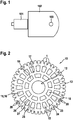
- Fig. 2
- ein Zahnrad, wie es bei einer Getriebe-Antriebseinheit der
Fig. 1 verwendet wird, in einer Seitenansicht, - Fig. 3
- eine perspektivische Teilansicht des erfindungsgemäßen Zahnrads im Bereich eines seiner Zähne und
- Fig. 4
- eine Darstellung mehrerer Längsrillen, die an einer Zahnflankenoberfläche eines Zahnes gemäß der
Fig. 3 angeordnet sind, in einer Schnittdarstellung.
- Fig. 1
- a gear drive unit in a highly simplified representation,
- Fig. 2
- a gear, as is the case with a transmission drive unit
Fig. 1 is used, in a side view, - Fig. 3
- a partial perspective view of the gear according to the invention in the region of one of his teeth and
- Fig. 4
- a representation of a plurality of longitudinal grooves, which on a tooth flank surface of a tooth according to the
Fig. 3 are arranged, in a sectional view.
Gleiche Bauteile bzw. Bauteile mit gleicher Funktion sind in den Figuren mit den gleichen Bezugsziffern versehen.The same components or components with the same function are provided in the figures with the same reference numerals.
In der
In der
Das Zahnrad 10 weist an seinem Außenumfang bevorzugt eine Vielzahl von Zähnen 1 auf, die im Ausführungsbeispiel eine Geradverzahnung ausbilden. Selbstverständlich ist es auch denkbar, dass die Zähne 1 eine Schrägverzahnung ausbilden. Die Zähne 1 des Zahnrades 10 wirken mit einer Gegenverzahnung eines nicht dargestellten Gegenelements, beispielsweise einer mit dem Antriebsmotor 101 verbundenen Antriebsschnecke, zusammen. Hierbei ist der Bereich, in dem ein Zahn 1 mit der entsprechenden Gegenverzahnung kämmt, in der
Das Zahnrad 10 weist in seiner Längsachse eine Bohrung 12 zur Lagerung des Zahnrads 10 z.B. in einem Achsstummel auf, der in dem Getriebegehäuse 102 angeordnet ist. Über die Bohrung 12 ist das Zahnrad 10 in der Getriebe-Antriebseinheit 100 drehbar angeordnet, so dass die Bohrung 12 gleichzeitig die Drehachse des Zahnrads 10 ausbildet.The
Sowohl aus fertigungstechnischen Gründen, insbesondere aufgrund der Schwindung des Materials, als auch z.B. aus Gründen eines möglichst geringen Gewichts, weist das Zahnrad 10 im Bereich der vorzugsweise ebenen Seitenflächen 13, 14 eine Vielzahl von Ausnehmungen 15,18 auf, die während der Herstellung des Zahnrads 10 durch eine entsprechend Formgebung bzw. Ausbildung des Spritzgusswerkzeuges ausgebildet bzw. hergestellt werden. Hierbei bilden die einen Ausnehmungen 15 in einem in Bezug auf die Bohrung 12 radial äußeren Bereich Aufnahmekammern bzw. Depots 16 zur Aufnahme bzw. Speicherung des nicht dargestellten Schmiermittels, insbesondere Fett, aus. Die Depots 16 sind über einen radial umlaufenden Zwischensteg 17 von den radial inneren Ausnehmungen 18 getrennt.Both for manufacturing reasons, in particular due to the shrinkage of the material, as well as for the sake of the lowest possible weight, the
Im Ausführungsbeispiel weist das Zahnrad 10 eine Vielzahl von Depots 16 bzw. ersten Ausnehmungen 15 auf, die in gleichmäßigen Winkelabständen über das Zahnrad 10 verteilt angeordnet sind. Wie insbesondere anhand der
Vorteilhafterweise bestehen die Zuführrillen 20 jeweils aus einem im Ausführungsbeispiel geradlinig ausgebildeten ersten Abschnitt 23, der in Richtung des Bereichs 21 in einen gebogenen Abschnitt 24 übergeht. Der gebogene Abschnitt 24 mündet wiederum im Bereich 21 des Zahns 1 an einer Zahnflankenkante 29 in Höhe etwa der Reibfläche 11 (
Um einen Transport von Schmiermittel aus dem Depot 16 in Richtung des Bereichs 21 zu vereinfachen bzw. zu begünstigen, kann es entsprechend der
Um zu vermeiden, dass Fett von dem Depot 16 in andere Bereiche des Zahnrads 10 gelangt, die insbesondere nicht geschmiert werden sollen, ist es weiterhin vorgesehen, dass die Kanten 26, 27, die die Ausnehmungen 15 bzw. die Depots 16 im Bereich der Seitenfläche 13, 14 begrenzen, möglichst scharfkantig bzw. mit einem möglichst geringen Krümmungsradius ausgebildet sind. Hierbei ist der Krümmungsradius derart klein zu wählen, wie dies aus fertigungstechnischen Gründen unter Berücksichtigung der Fertigungskosten möglich ist. Darüber hinaus sind insbesondere die Seitenflächen 13, 14 bzw. Bereiche, in denen kein Transport von Schmiermittel stattfinden soll, mit einer möglichst geringen Rauigkeit zu versehen.In order to avoid that grease passes from the depot 16 in other areas of the
Wie aus einer Zusammenschau der
Wichtig ist es auch, dass die Längsrillen 30 bevorzugt, wie die Zuführrillen 20, mit einer zusätzlichen Kapillarwirkung in Richtung zur Reibfläche 11 hin ausgestattet sind. Hierzu wird nochmals auf die
Auch die Längsrillen 30 und die Zahnflankenkantenabschnitte 25 werden, ebenso wie die Zuführrillen 20, bevorzugt bereits während der Herstellung des Zahnrads 10 berücksichtigt bzw. durch eine entsprechende Formgebung des Spritzgusswerkzeugs erzeugt. Wie insbesondere anhand der
Wichtig ist auch, dass der Zahnfußbereich 32 eines Zahns 1 keine Längsrillen 30 aufweist sowie bevorzugt eine größere Rauigkeit, z.B. R27 hat als die Reibfläche 11, die beispielsweise eine Rauigkeit von R21 aufweist.It is also important that the
Das soweit beschriebene erfindungsgemäße Zahnrad 10 bzw. die Getriebe-Antriebseinheit 100 können in vielfältiger Art und Weise abgewandelt bzw. modifiziert werden, ohne vom Erfindungsgedanken abzuweichen. Dieser besteht in dem Vorsehen bzw. der Ausbildung wenigstens einer Längsrille 30 im Bereich des Zahns 1. So ist es selbstverständlich auch denkbar, dass das Zahnrad 10 nicht aus Kunststoff, sondern aus Metall ausgebildet sein kann. Weiterhin kann auf die Ausbildung der Zuführrillen 20 verzichtet werden, die die Depots 16 mit den Längsrillen 30 verbinden. In diesem Fall bilden die Längsrillen 30 das einzige Schmiermitteldepot aus. In einer weiteren Ausgestaltung der Erfindung ist es auch denkbar, dass die Längsrillen 30 als über die gesamte Breite B des Zahns 1 verlaufende Längsrillen 30 ausgebildet sind, oder erst beabstandet von der Zahnflankenkante 29 beginnen und zum Beispiel auch bis in den Bereich der Reibfläche 11 hineinreichen, insbesondere, wenn die Tragfähigkeit der Zähne 1 für den Anwendungsfall nicht kritisch ist.The
Claims (15)
dadurch gekennzeichnet, dass
an der Zahnflankenoberfläche (22) wenigstens eine Längsrille (30) zur Zuführung des Schmiermittels in Richtung zum Reibbereich (11) ausgebildet ist.Gear (10) which is mounted in a rotation axis and on whose circumference preferably a plurality of teeth (1) for transmitting a torque to a cooperating with the gear (10) counter element are arranged, wherein a friction region (11) between a tooth ( 1) and the counter-element on a tooth flank surface (22) is provided with lubricant,
characterized in that
at least one longitudinal groove (30) for supplying the lubricant in the direction of the friction region (11) is formed on the tooth flank surface (22).
dadurch gekennzeichnet,
dass die wenigstens eine Längsrille (30) von wenigstens einer Seitenfläche (13, 14) des Zahnrads (10), insbesondere vom Bereich der Zahnflankenkante (29) des Zahns (1), ausgeht.Gear according to claim 1,
characterized,
that the at least one longitudinal groove (30) of at least one side surface (13, 14) of the gear (10), in particular from the area of the tooth flank edge (29) of the tooth (1), runs out.
dadurch gekennzeichnet,
dass die wenigstens eine Längsrille (30) bis zur Reibfläche (11) reicht, die Reibfläche (11) jedoch zumindest im Wesentlichen rillenfrei ausgebildet ist.Gear according to claim 1 or 2,
characterized,
in that the at least one longitudinal groove (30) extends as far as the friction surface (11), but the friction surface (11) is at least substantially groove-free.
dadurch gekennzeichnet,
dass die Reibfläche (11) eine geringere Rauigkeit aufweist als der Zahnfußbereich (32) der Zahnflankenoberfläche (22).Cogwheel according to one of claims 1 to 3,
characterized,
that the friction surface (11) has a lower roughness than the tooth-root region (32) of the tooth flank surface (22).
dadurch gekennzeichnet,
dass der Zahnfußbereich (32) rillenfrei ausgebildet ist.Cogwheel according to one of claims 1 to 4,
characterized,
that the tooth base (32) is formed groove-free.
dadurch gekennzeichnet,
dass von beiden Seitenflächen (13, 14) des Zahnrads (10) jeweils wenigstens eine Längsrille (30) ausgeht, dass die Längsrillen (30) in etwa gleich lang ausgebildet sind, und dass die Länge (I) der Längsrille (30), die von der jeweiligen Seitenfläche (13, 14) ausgeht, bezogen auf die Zahnradbreite (B), zwischen 30% und 70%, bevorzugt 45% bis 55% der Zahnradbreite (B) beträgt.Cogwheel according to one of claims 1 to 5,
characterized,
in that at least one longitudinal groove (30) originates from both side surfaces (13, 14) of the toothed wheel (10), that the longitudinal grooves (30) are approximately of equal length, and that the length (I) of the longitudinal groove (30), from the respective side surface (13, 14), based on the gear width (B), between 30% and 70%, preferably 45% to 55% of the gear width (B).
dadurch gekennzeichnet,
dass die Breite (b) und Tiefe (t) der Längsrille (30) zwischen 5µm und 50µm, insbesondere 20µm beträgt, und dass beim Vorhandensein mehrere Längsrillen (30) diese bevorzugt parallel zueinander mit einem Abstand (a) von insbesondere etwa 20µm angeordnet sind.Gear according to one of claims 1 to 6,
characterized,
that the width (b) and depth (t) of the longitudinal groove (30) between 5 .mu.m and 50 .mu.m, in particular 20 .mu.m, and that in the presence of a plurality of longitudinal grooves (30) these are preferably arranged parallel to each other with a distance (a) of in particular about 20 microns ,
dadurch gekennzeichnet,
dass in einem radialen Zwischenbereich zwischen der Drehachse und den Zähnen (1) wenigstens ein Depot (16) für Schmiermittel zur zusätzlichen Versorgung der Reibflächen (11) der Zähne (1) angeordnet ist, wobei der Zwischenbereich wenigstens eine Ausnehmung (15) zur Ausbildung des Depots (16) aufweist, und wobei zwischen der Ausnehmung (15) für das Depot (16) und dem Bereich (21) der Zähne (1) an einer Oberfläche wenigstens einer der Seitenflächen (13, 14) des Zahnrads (10) wenigstens eine Schmiermittelführung, insbesondere in Form einer Zuführrille (20) ausgebildet ist, die die Ausnehmung (15) bzw. das Depot (16) mit dem Bereich (21) der Zähne (1) verbindet.Cogwheel according to one of claims 1 to 7,
characterized,
is arranged that in a radial intermediate region between the rotational axis and the teeth (1) at least one vault (16) for lubricant to the additional supply of the friction surfaces (11) of the teeth (1), wherein the intermediate region at least one recess (15) to form the Depot (16), and wherein between the recess (15) for the depot (16) and the region (21) of the teeth (1) on a surface of at least one of the side surfaces (13, 14) of the gear (10) at least one Lubricant guide, in particular in the form of a Zuführrille (20) is formed, which connects the recess (15) and the depot (16) with the region (21) of the teeth (1).
dadurch gekennzeichnet,
dass die wenigstens eine Seitenfläche (13, 14) als stetige, insbesondere als ebene Seitenfläche (13, 14) ausgebildet ist.Gear according to one of claims 2 to 8,
characterized,
in that the at least one side face (13, 14) is formed as a continuous, in particular as a flat side face (13, 14).
dadurch gekennzeichnet,
dass die Zuführrille (20), ausgehend von der Ausnehmung (15), einen im Wesentlichen zur Drehachse gerichteten ersten Abschnitt (23) aufweist, der in einen gebogenen zweiten Abschnitt (24) übergeht, wobei der zweite Abschnitt (24) im Bereich (21) der Zähne (1) in Höhe der Reibfläche (11) an einer Zahnflankenkante (29) endet.Gear according to claim 8 or 9,
characterized,
in that the feed groove (20), starting from the recess (15), has a first section (23) directed substantially towards the axis of rotation, which merges into a curved second section (24), the second section (24) being in the region (21 ) of the teeth (1) at the level of the friction surface (11) ends at a tooth flank edge (29).
dadurch gekennzeichnet,
dass der Übergangsbereich von der Zuführrille (20) in die Längsrille (30) an der Zahnflankenkante (29) gerundet ausgebildet ist.Cogwheel according to one of claims 8 to 10,
characterized,
is configured that the transitional region of the feeding groove (20) in the longitudinal groove (30) on the tooth flank edge (29) rounded.
dadurch gekennzeichnet,
dass das Zahnrad (10) aus Kunststoff - insbesondere aus POM (Polyoxymethylen) - besteht und als Spritzgußteil ausgebildet ist, wobei die wenigstens eine Längsrille (30) und/oder die Ausnehmung (15) für das Depot (16) während des Spritzprozesses durch eine entsprechende Ausgestaltung des Spritzgusswerkzeuges ausgebildet wird.Cogwheel according to one of claims 1 to 11,
characterized,
in that the toothed wheel (10) consists of plastic - in particular of POM (polyoxymethylene) - and is designed as an injection molding, wherein the at least one longitudinal groove (30) and / or the recess (15) for the depot (16) during the injection process by a corresponding embodiment of the injection molding tool is formed.
dadurch gekennzeichnet,
dass die Ausnehmung (15) für das Depot (16) in Höhe der Seitenfläche (13, 14) in dem nicht mit der Zuführrille (20) verbundenen Bereich mit wenigstens einer scharfkantig ausgebildeten Kante (26, 27) und/oder die Seitenfläche (13, 14) in dem nicht mit der Zuführrille (20) verbundenen Bereich mit einer relativ glatten Oberfläche ausgebildet ist.Gear according to one of claims 8 to 12,
characterized,
in that the recess (15) for the depot (16) at the level of the side face (13, 14) in the region not connected to the feed groove (20) has at least one sharp-edged edge (26, 27) and / or the side face (13 , 14) in which the area not connected to the feed groove (20) is formed with a relatively smooth surface.
dadurch gekennzeichnet,
dass die wenigstens eine Längsrille (30) und ggf. die Zuführrille (20) mit Maßnahmen zur Ausbildung einer Kapillarwirkung für das Schmiermittel in Richtung der Reibfläche (11) versehen ist.Cogwheel according to one of claims 1 to 13,
characterized,
in that the at least one longitudinal groove (30) and optionally the feed groove (20) are provided with measures for forming a capillary action for the lubricant in the direction of the friction surface (11).
Applications Claiming Priority (1)
| Application Number | Priority Date | Filing Date | Title |
|---|---|---|---|
| DE201110006276 DE102011006276A1 (en) | 2011-03-28 | 2011-03-28 | Zanhrad as well as transmission drive unit |
Publications (3)
| Publication Number | Publication Date |
|---|---|
| EP2508778A2 true EP2508778A2 (en) | 2012-10-10 |
| EP2508778A3 EP2508778A3 (en) | 2015-06-24 |
| EP2508778B1 EP2508778B1 (en) | 2019-08-07 |
Family
ID=45557958
Family Applications (1)
| Application Number | Title | Priority Date | Filing Date |
|---|---|---|---|
| EP12153408.5A Active EP2508778B1 (en) | 2011-03-28 | 2012-02-01 | Gear wheel and gear-drive unit |
Country Status (2)
| Country | Link |
|---|---|
| EP (1) | EP2508778B1 (en) |
| DE (1) | DE102011006276A1 (en) |
Cited By (3)
| Publication number | Priority date | Publication date | Assignee | Title |
|---|---|---|---|---|
| DE102016206141A1 (en) | 2016-04-13 | 2017-10-19 | Robert Bosch Gmbh | Device with a frictional contact and method for operating a device with a frictional contact |
| DE102016206139A1 (en) | 2016-04-13 | 2017-10-19 | Robert Bosch Gmbh | Device with a frictional contact and method for operating a device with a frictional contact |
| CN107747622A (en) * | 2017-11-03 | 2018-03-02 | 六安市金龙齿轮有限公司 | A kind of gap oil-filling type superposition gear and its gear working method |
Families Citing this family (3)
| Publication number | Priority date | Publication date | Assignee | Title |
|---|---|---|---|---|
| CN108253114B (en) * | 2017-12-21 | 2021-12-10 | 安徽工程大学 | Self-lubricating gear with micro-texture |
| US11105411B2 (en) * | 2018-02-28 | 2021-08-31 | Sikorsky Aircraft Corporation | Secondary lubrication for gears and gearboxes |
| DE102018217617A1 (en) | 2018-10-15 | 2020-04-16 | Robert Bosch Gmbh | Method for producing a gear worm, which is arranged in particular on an armature shaft, and such a gear worm |
Family Cites Families (5)
| Publication number | Priority date | Publication date | Assignee | Title |
|---|---|---|---|---|
| US3424022A (en) * | 1967-01-23 | 1969-01-28 | Babcock & Wilcox Co | Hydrostatic gearing |
| JPH10203436A (en) * | 1997-01-20 | 1998-08-04 | Hitachi Ltd | Vehicle for earth work |
| JP2004092697A (en) * | 2002-08-29 | 2004-03-25 | Chiba Dies:Kk | Gear |
| DE102009000210A1 (en) | 2009-01-14 | 2010-07-15 | Robert Bosch Gmbh | Element, particularly gear element or gear wheel, for use in device, particularly gear, guiding device, bearing device and valve or drive device, has upper surface provided with upper surface capillarity structure |
| DE102009000297A1 (en) * | 2009-01-19 | 2010-07-22 | Robert Bosch Gmbh | Transmission element, transmission, device with gear and method for producing a transmission element |
-
2011
- 2011-03-28 DE DE201110006276 patent/DE102011006276A1/en not_active Withdrawn
-
2012
- 2012-02-01 EP EP12153408.5A patent/EP2508778B1/en active Active
Cited By (5)
| Publication number | Priority date | Publication date | Assignee | Title |
|---|---|---|---|---|
| DE102016206141A1 (en) | 2016-04-13 | 2017-10-19 | Robert Bosch Gmbh | Device with a frictional contact and method for operating a device with a frictional contact |
| DE102016206139A1 (en) | 2016-04-13 | 2017-10-19 | Robert Bosch Gmbh | Device with a frictional contact and method for operating a device with a frictional contact |
| EP3242059A2 (en) | 2016-04-13 | 2017-11-08 | Robert Bosch GmbH | Device with a frictional contact and method for operating a device comprising a frictional contact |
| EP3242048A1 (en) | 2016-04-13 | 2017-11-08 | Robert Bosch GmbH | Device with a frictional contact and method for operating a device comprising a frictional contact |
| CN107747622A (en) * | 2017-11-03 | 2018-03-02 | 六安市金龙齿轮有限公司 | A kind of gap oil-filling type superposition gear and its gear working method |
Also Published As
| Publication number | Publication date |
|---|---|
| EP2508778A3 (en) | 2015-06-24 |
| EP2508778B1 (en) | 2019-08-07 |
| DE102011006276A1 (en) | 2012-10-04 |
Similar Documents
| Publication | Publication Date | Title |
|---|---|---|
| EP2505424B1 (en) | Spindle drive for horizontal adjustment of a motor vehicle seat | |
| EP2508778B1 (en) | Gear wheel and gear-drive unit | |
| EP2836416B1 (en) | Floating bearing for a steering gear | |
| EP2221510B1 (en) | Planet wheel with a bolt comprising an axial nut | |
| WO2007131604A1 (en) | Lubricating device with lubricating pinion | |
| AT506562A1 (en) | PULLEY | |
| DE3015681C2 (en) | Lubricating device for a radial bearing | |
| DE2616765A1 (en) | W-N GEAR WITH A SINGLE-FLANKED OR DOUBLE-FLANKED TOOTH PROFILE | |
| EP2710282A1 (en) | Planetary gear system | |
| WO2008113396A1 (en) | Lubricating pinion and lubricating device | |
| DE102012111941B4 (en) | Seat fitting for a motor vehicle seat | |
| EP2129937B1 (en) | Two-component gear wheel | |
| DE202008016335U1 (en) | Motor-gear unit for actuating an adjusting element of a vehicle | |
| WO2015067262A2 (en) | Sliding sleeve for supporting sun gears | |
| DE102014104949B4 (en) | gear | |
| EP2691673A1 (en) | Planet gear for a planetary gear train | |
| DE102014106533A1 (en) | Disc brake for a commercial vehicle | |
| DE112012004609B4 (en) | worm gear | |
| DE102008058873A1 (en) | Gear box i.e. transfer gear-box, has clutch distributing torque to output shafts, and gear wheel plunged into oil sump of gear and partially enclosed by shielding element, where shielding element is connected to section of wheel | |
| EP2834539A1 (en) | Gearbox arrangement for a rail vehicle | |
| DE19628520C2 (en) | Self-locking gear | |
| DE102014218303A1 (en) | steering gear | |
| DE102005001448A1 (en) | worm | |
| DE102011003249A1 (en) | Gear assembly for rail vehicle, has driving and driven wheels fixed to housing shell along toothing of wheels for increasing lubricant or oil supply from lubricant inlet to lubricant outlet in circumferential direction | |
| DE102018217617A1 (en) | Method for producing a gear worm, which is arranged in particular on an armature shaft, and such a gear worm |
Legal Events
| Date | Code | Title | Description |
|---|---|---|---|
| PUAI | Public reference made under article 153(3) epc to a published international application that has entered the european phase |
Free format text: ORIGINAL CODE: 0009012 |
|
| AK | Designated contracting states |
Kind code of ref document: A2 Designated state(s): AL AT BE BG CH CY CZ DE DK EE ES FI FR GB GR HR HU IE IS IT LI LT LU LV MC MK MT NL NO PL PT RO RS SE SI SK SM TR |
|
| AX | Request for extension of the european patent |
Extension state: BA ME |
|
| PUAL | Search report despatched |
Free format text: ORIGINAL CODE: 0009013 |
|
| AK | Designated contracting states |
Kind code of ref document: A3 Designated state(s): AL AT BE BG CH CY CZ DE DK EE ES FI FR GB GR HR HU IE IS IT LI LT LU LV MC MK MT NL NO PL PT RO RS SE SI SK SM TR |
|
| AX | Request for extension of the european patent |
Extension state: BA ME |
|
| RIC1 | Information provided on ipc code assigned before grant |
Ipc: F16H 57/04 20100101AFI20150521BHEP |
|
| 17P | Request for examination filed |
Effective date: 20160104 |
|
| RBV | Designated contracting states (corrected) |
Designated state(s): AL AT BE BG CH CY CZ DE DK EE ES FI FR GB GR HR HU IE IS IT LI LT LU LV MC MK MT NL NO PL PT RO RS SE SI SK SM TR |
|
| STAA | Information on the status of an ep patent application or granted ep patent |
Free format text: STATUS: EXAMINATION IS IN PROGRESS |
|
| 17Q | First examination report despatched |
Effective date: 20170223 |
|
| GRAJ | Information related to disapproval of communication of intention to grant by the applicant or resumption of examination proceedings by the epo deleted |
Free format text: ORIGINAL CODE: EPIDOSDIGR1 |
|
| STAA | Information on the status of an ep patent application or granted ep patent |
Free format text: STATUS: GRANT OF PATENT IS INTENDED |
|
| GRAP | Despatch of communication of intention to grant a patent |
Free format text: ORIGINAL CODE: EPIDOSNIGR1 |
|
| INTG | Intention to grant announced |
Effective date: 20190228 |
|
| GRAS | Grant fee paid |
Free format text: ORIGINAL CODE: EPIDOSNIGR3 |
|
| GRAA | (expected) grant |
Free format text: ORIGINAL CODE: 0009210 |
|
| STAA | Information on the status of an ep patent application or granted ep patent |
Free format text: STATUS: THE PATENT HAS BEEN GRANTED |
|
| AK | Designated contracting states |
Kind code of ref document: B1 Designated state(s): AL AT BE BG CH CY CZ DE DK EE ES FI FR GB GR HR HU IE IS IT LI LT LU LV MC MK MT NL NO PL PT RO RS SE SI SK SM TR |
|
| REG | Reference to a national code |
Ref country code: GB Ref legal event code: FG4D Free format text: NOT ENGLISH |
|
| REG | Reference to a national code |
Ref country code: CH Ref legal event code: EP Ref country code: AT Ref legal event code: REF Ref document number: 1164381 Country of ref document: AT Kind code of ref document: T Effective date: 20190815 |
|
| REG | Reference to a national code |
Ref country code: DE Ref legal event code: R096 Ref document number: 502012015108 Country of ref document: DE |
|
| REG | Reference to a national code |
Ref country code: IE Ref legal event code: FG4D Free format text: LANGUAGE OF EP DOCUMENT: GERMAN |
|
| REG | Reference to a national code |
Ref country code: NL Ref legal event code: MP Effective date: 20190807 |
|
| REG | Reference to a national code |
Ref country code: LT Ref legal event code: MG4D |
|
| PG25 | Lapsed in a contracting state [announced via postgrant information from national office to epo] |
Ref country code: FI Free format text: LAPSE BECAUSE OF FAILURE TO SUBMIT A TRANSLATION OF THE DESCRIPTION OR TO PAY THE FEE WITHIN THE PRESCRIBED TIME-LIMIT Effective date: 20190807 Ref country code: NO Free format text: LAPSE BECAUSE OF FAILURE TO SUBMIT A TRANSLATION OF THE DESCRIPTION OR TO PAY THE FEE WITHIN THE PRESCRIBED TIME-LIMIT Effective date: 20191107 Ref country code: HR Free format text: LAPSE BECAUSE OF FAILURE TO SUBMIT A TRANSLATION OF THE DESCRIPTION OR TO PAY THE FEE WITHIN THE PRESCRIBED TIME-LIMIT Effective date: 20190807 Ref country code: NL Free format text: LAPSE BECAUSE OF FAILURE TO SUBMIT A TRANSLATION OF THE DESCRIPTION OR TO PAY THE FEE WITHIN THE PRESCRIBED TIME-LIMIT Effective date: 20190807 Ref country code: SE Free format text: LAPSE BECAUSE OF FAILURE TO SUBMIT A TRANSLATION OF THE DESCRIPTION OR TO PAY THE FEE WITHIN THE PRESCRIBED TIME-LIMIT Effective date: 20190807 Ref country code: PT Free format text: LAPSE BECAUSE OF FAILURE TO SUBMIT A TRANSLATION OF THE DESCRIPTION OR TO PAY THE FEE WITHIN THE PRESCRIBED TIME-LIMIT Effective date: 20191209 Ref country code: BG Free format text: LAPSE BECAUSE OF FAILURE TO SUBMIT A TRANSLATION OF THE DESCRIPTION OR TO PAY THE FEE WITHIN THE PRESCRIBED TIME-LIMIT Effective date: 20191107 Ref country code: LT Free format text: LAPSE BECAUSE OF FAILURE TO SUBMIT A TRANSLATION OF THE DESCRIPTION OR TO PAY THE FEE WITHIN THE PRESCRIBED TIME-LIMIT Effective date: 20190807 |
|
| PG25 | Lapsed in a contracting state [announced via postgrant information from national office to epo] |
Ref country code: AL Free format text: LAPSE BECAUSE OF FAILURE TO SUBMIT A TRANSLATION OF THE DESCRIPTION OR TO PAY THE FEE WITHIN THE PRESCRIBED TIME-LIMIT Effective date: 20190807 Ref country code: LV Free format text: LAPSE BECAUSE OF FAILURE TO SUBMIT A TRANSLATION OF THE DESCRIPTION OR TO PAY THE FEE WITHIN THE PRESCRIBED TIME-LIMIT Effective date: 20190807 Ref country code: IS Free format text: LAPSE BECAUSE OF FAILURE TO SUBMIT A TRANSLATION OF THE DESCRIPTION OR TO PAY THE FEE WITHIN THE PRESCRIBED TIME-LIMIT Effective date: 20191207 Ref country code: RS Free format text: LAPSE BECAUSE OF FAILURE TO SUBMIT A TRANSLATION OF THE DESCRIPTION OR TO PAY THE FEE WITHIN THE PRESCRIBED TIME-LIMIT Effective date: 20190807 Ref country code: GR Free format text: LAPSE BECAUSE OF FAILURE TO SUBMIT A TRANSLATION OF THE DESCRIPTION OR TO PAY THE FEE WITHIN THE PRESCRIBED TIME-LIMIT Effective date: 20191108 Ref country code: ES Free format text: LAPSE BECAUSE OF FAILURE TO SUBMIT A TRANSLATION OF THE DESCRIPTION OR TO PAY THE FEE WITHIN THE PRESCRIBED TIME-LIMIT Effective date: 20190807 |
|
| PG25 | Lapsed in a contracting state [announced via postgrant information from national office to epo] |
Ref country code: TR Free format text: LAPSE BECAUSE OF FAILURE TO SUBMIT A TRANSLATION OF THE DESCRIPTION OR TO PAY THE FEE WITHIN THE PRESCRIBED TIME-LIMIT Effective date: 20190807 |
|
| RAP2 | Party data changed (patent owner data changed or rights of a patent transferred) |
Owner name: ROBERT BOSCH GMBH |
|
| PG25 | Lapsed in a contracting state [announced via postgrant information from national office to epo] |
Ref country code: IT Free format text: LAPSE BECAUSE OF FAILURE TO SUBMIT A TRANSLATION OF THE DESCRIPTION OR TO PAY THE FEE WITHIN THE PRESCRIBED TIME-LIMIT Effective date: 20190807 Ref country code: RO Free format text: LAPSE BECAUSE OF FAILURE TO SUBMIT A TRANSLATION OF THE DESCRIPTION OR TO PAY THE FEE WITHIN THE PRESCRIBED TIME-LIMIT Effective date: 20190807 Ref country code: PL Free format text: LAPSE BECAUSE OF FAILURE TO SUBMIT A TRANSLATION OF THE DESCRIPTION OR TO PAY THE FEE WITHIN THE PRESCRIBED TIME-LIMIT Effective date: 20190807 Ref country code: DK Free format text: LAPSE BECAUSE OF FAILURE TO SUBMIT A TRANSLATION OF THE DESCRIPTION OR TO PAY THE FEE WITHIN THE PRESCRIBED TIME-LIMIT Effective date: 20190807 Ref country code: EE Free format text: LAPSE BECAUSE OF FAILURE TO SUBMIT A TRANSLATION OF THE DESCRIPTION OR TO PAY THE FEE WITHIN THE PRESCRIBED TIME-LIMIT Effective date: 20190807 |
|
| PG25 | Lapsed in a contracting state [announced via postgrant information from national office to epo] |
Ref country code: CZ Free format text: LAPSE BECAUSE OF FAILURE TO SUBMIT A TRANSLATION OF THE DESCRIPTION OR TO PAY THE FEE WITHIN THE PRESCRIBED TIME-LIMIT Effective date: 20190807 Ref country code: IS Free format text: LAPSE BECAUSE OF FAILURE TO SUBMIT A TRANSLATION OF THE DESCRIPTION OR TO PAY THE FEE WITHIN THE PRESCRIBED TIME-LIMIT Effective date: 20200224 Ref country code: SM Free format text: LAPSE BECAUSE OF FAILURE TO SUBMIT A TRANSLATION OF THE DESCRIPTION OR TO PAY THE FEE WITHIN THE PRESCRIBED TIME-LIMIT Effective date: 20190807 Ref country code: SK Free format text: LAPSE BECAUSE OF FAILURE TO SUBMIT A TRANSLATION OF THE DESCRIPTION OR TO PAY THE FEE WITHIN THE PRESCRIBED TIME-LIMIT Effective date: 20190807 |
|
| REG | Reference to a national code |
Ref country code: DE Ref legal event code: R097 Ref document number: 502012015108 Country of ref document: DE |
|
| PLBE | No opposition filed within time limit |
Free format text: ORIGINAL CODE: 0009261 |
|
| STAA | Information on the status of an ep patent application or granted ep patent |
Free format text: STATUS: NO OPPOSITION FILED WITHIN TIME LIMIT |
|
| PG2D | Information on lapse in contracting state deleted |
Ref country code: IS |
|
| 26N | No opposition filed |
Effective date: 20200603 |
|
| PG25 | Lapsed in a contracting state [announced via postgrant information from national office to epo] |
Ref country code: SI Free format text: LAPSE BECAUSE OF FAILURE TO SUBMIT A TRANSLATION OF THE DESCRIPTION OR TO PAY THE FEE WITHIN THE PRESCRIBED TIME-LIMIT Effective date: 20190807 |
|
| REG | Reference to a national code |
Ref country code: CH Ref legal event code: PL |
|
| GBPC | Gb: european patent ceased through non-payment of renewal fee |
Effective date: 20200201 |
|
| REG | Reference to a national code |
Ref country code: BE Ref legal event code: MM Effective date: 20200229 |
|
| PG25 | Lapsed in a contracting state [announced via postgrant information from national office to epo] |
Ref country code: LU Free format text: LAPSE BECAUSE OF NON-PAYMENT OF DUE FEES Effective date: 20200201 Ref country code: MC Free format text: LAPSE BECAUSE OF FAILURE TO SUBMIT A TRANSLATION OF THE DESCRIPTION OR TO PAY THE FEE WITHIN THE PRESCRIBED TIME-LIMIT Effective date: 20190807 |
|
| PG25 | Lapsed in a contracting state [announced via postgrant information from national office to epo] |
Ref country code: CH Free format text: LAPSE BECAUSE OF NON-PAYMENT OF DUE FEES Effective date: 20200229 Ref country code: LI Free format text: LAPSE BECAUSE OF NON-PAYMENT OF DUE FEES Effective date: 20200229 |
|
| PG25 | Lapsed in a contracting state [announced via postgrant information from national office to epo] |
Ref country code: IE Free format text: LAPSE BECAUSE OF NON-PAYMENT OF DUE FEES Effective date: 20200201 Ref country code: GB Free format text: LAPSE BECAUSE OF NON-PAYMENT OF DUE FEES Effective date: 20200201 |
|
| PG25 | Lapsed in a contracting state [announced via postgrant information from national office to epo] |
Ref country code: BE Free format text: LAPSE BECAUSE OF NON-PAYMENT OF DUE FEES Effective date: 20200229 |
|
| REG | Reference to a national code |
Ref country code: AT Ref legal event code: MM01 Ref document number: 1164381 Country of ref document: AT Kind code of ref document: T Effective date: 20200201 |
|
| PGFP | Annual fee paid to national office [announced via postgrant information from national office to epo] |
Ref country code: FR Payment date: 20210217 Year of fee payment: 10 |
|
| PG25 | Lapsed in a contracting state [announced via postgrant information from national office to epo] |
Ref country code: AT Free format text: LAPSE BECAUSE OF NON-PAYMENT OF DUE FEES Effective date: 20200201 |
|
| REG | Reference to a national code |
Ref country code: DE Ref legal event code: R084 Ref document number: 502012015108 Country of ref document: DE |
|
| PG25 | Lapsed in a contracting state [announced via postgrant information from national office to epo] |
Ref country code: MT Free format text: LAPSE BECAUSE OF FAILURE TO SUBMIT A TRANSLATION OF THE DESCRIPTION OR TO PAY THE FEE WITHIN THE PRESCRIBED TIME-LIMIT Effective date: 20190807 Ref country code: CY Free format text: LAPSE BECAUSE OF FAILURE TO SUBMIT A TRANSLATION OF THE DESCRIPTION OR TO PAY THE FEE WITHIN THE PRESCRIBED TIME-LIMIT Effective date: 20190807 |
|
| PG25 | Lapsed in a contracting state [announced via postgrant information from national office to epo] |
Ref country code: MK Free format text: LAPSE BECAUSE OF FAILURE TO SUBMIT A TRANSLATION OF THE DESCRIPTION OR TO PAY THE FEE WITHIN THE PRESCRIBED TIME-LIMIT Effective date: 20190807 |
|
| PGFP | Annual fee paid to national office [announced via postgrant information from national office to epo] |
Ref country code: DE Payment date: 20220426 Year of fee payment: 11 |
|
| PG25 | Lapsed in a contracting state [announced via postgrant information from national office to epo] |
Ref country code: FR Free format text: LAPSE BECAUSE OF NON-PAYMENT OF DUE FEES Effective date: 20220228 |
|
| REG | Reference to a national code |
Ref country code: DE Ref legal event code: R119 Ref document number: 502012015108 Country of ref document: DE |
|
| PG25 | Lapsed in a contracting state [announced via postgrant information from national office to epo] |
Ref country code: DE Free format text: LAPSE BECAUSE OF NON-PAYMENT OF DUE FEES Effective date: 20230901 |