EP2507796B1 - Crayon de combustible nucléaire et procédé de fabrication de pastilles d'un tel crayon - Google Patents
Crayon de combustible nucléaire et procédé de fabrication de pastilles d'un tel crayon Download PDFInfo
- Publication number
- EP2507796B1 EP2507796B1 EP10787098.2A EP10787098A EP2507796B1 EP 2507796 B1 EP2507796 B1 EP 2507796B1 EP 10787098 A EP10787098 A EP 10787098A EP 2507796 B1 EP2507796 B1 EP 2507796B1
- Authority
- EP
- European Patent Office
- Prior art keywords
- fuel
- pellets
- length
- sheath
- cladding
- Prior art date
- Legal status (The legal status is an assumption and is not a legal conclusion. Google has not performed a legal analysis and makes no representation as to the accuracy of the status listed.)
- Not-in-force
Links
- 239000008188 pellet Substances 0.000 title claims description 169
- 239000000446 fuel Substances 0.000 title claims description 137
- 239000003758 nuclear fuel Substances 0.000 title claims description 26
- 238000004519 manufacturing process Methods 0.000 title claims description 11
- 238000000034 method Methods 0.000 title claims description 5
- 239000000463 material Substances 0.000 claims description 33
- 238000005253 cladding Methods 0.000 claims description 31
- 229910052778 Plutonium Inorganic materials 0.000 claims description 9
- 229910052770 Uranium Inorganic materials 0.000 claims description 9
- XLYOFNOQVPJJNP-UHFFFAOYSA-N water Substances O XLYOFNOQVPJJNP-UHFFFAOYSA-N 0.000 claims description 9
- 239000000956 alloy Substances 0.000 claims description 7
- 229910045601 alloy Inorganic materials 0.000 claims description 7
- 229910001093 Zr alloy Inorganic materials 0.000 claims description 5
- 239000000919 ceramic Substances 0.000 claims description 5
- 229910010293 ceramic material Inorganic materials 0.000 claims description 5
- 239000000203 mixture Substances 0.000 claims description 5
- FLDALJIYKQCYHH-UHFFFAOYSA-N plutonium(iv) oxide Chemical class [O-2].[O-2].[Pu+4] FLDALJIYKQCYHH-UHFFFAOYSA-N 0.000 claims description 4
- 239000000843 powder Substances 0.000 claims description 4
- WZECUPJJEIXUKY-UHFFFAOYSA-N [O-2].[O-2].[O-2].[U+6] Chemical compound [O-2].[O-2].[O-2].[U+6] WZECUPJJEIXUKY-UHFFFAOYSA-N 0.000 claims description 3
- 229910000439 uranium oxide Inorganic materials 0.000 claims description 3
- 229910052720 vanadium Inorganic materials 0.000 claims description 3
- LEONUFNNVUYDNQ-UHFFFAOYSA-N vanadium atom Chemical compound [V] LEONUFNNVUYDNQ-UHFFFAOYSA-N 0.000 claims description 3
- 229910009817 Ti3SiC2 Inorganic materials 0.000 claims 1
- 239000007769 metal material Substances 0.000 claims 1
- 235000010603 pastilles Nutrition 0.000 description 67
- 230000003993 interaction Effects 0.000 description 42
- 230000004992 fission Effects 0.000 description 23
- 239000007789 gas Substances 0.000 description 20
- 239000002826 coolant Substances 0.000 description 16
- 238000003825 pressing Methods 0.000 description 11
- 230000000930 thermomechanical effect Effects 0.000 description 10
- 238000012546 transfer Methods 0.000 description 9
- 230000008961 swelling Effects 0.000 description 8
- 238000013461 design Methods 0.000 description 7
- 230000004308 accommodation Effects 0.000 description 6
- 230000006872 improvement Effects 0.000 description 6
- 230000002093 peripheral effect Effects 0.000 description 6
- 101100234547 Caenorhabditis elegans rod-1 gene Proteins 0.000 description 5
- 238000002485 combustion reaction Methods 0.000 description 5
- 230000000694 effects Effects 0.000 description 5
- 239000010410 layer Substances 0.000 description 5
- 230000007246 mechanism Effects 0.000 description 5
- 238000005457 optimization Methods 0.000 description 5
- 230000015556 catabolic process Effects 0.000 description 4
- 238000006731 degradation reaction Methods 0.000 description 4
- 238000001125 extrusion Methods 0.000 description 4
- 239000002245 particle Substances 0.000 description 4
- 238000005245 sintering Methods 0.000 description 4
- 230000008901 benefit Effects 0.000 description 3
- 238000006243 chemical reaction Methods 0.000 description 3
- 230000006835 compression Effects 0.000 description 3
- 238000007906 compression Methods 0.000 description 3
- 239000000470 constituent Substances 0.000 description 3
- 238000011049 filling Methods 0.000 description 3
- 230000004907 flux Effects 0.000 description 3
- 230000008707 rearrangement Effects 0.000 description 3
- 239000003870 refractory metal Substances 0.000 description 3
- 239000012780 transparent material Substances 0.000 description 3
- 239000011800 void material Substances 0.000 description 3
- 101000579646 Penaeus vannamei Penaeidin-1 Proteins 0.000 description 2
- 230000009471 action Effects 0.000 description 2
- 125000004429 atom Chemical group 0.000 description 2
- 238000005452 bending Methods 0.000 description 2
- 239000011247 coating layer Substances 0.000 description 2
- 239000002131 composite material Substances 0.000 description 2
- 238000005260 corrosion Methods 0.000 description 2
- 230000007797 corrosion Effects 0.000 description 2
- 230000003247 decreasing effect Effects 0.000 description 2
- 238000000280 densification Methods 0.000 description 2
- 238000010438 heat treatment Methods 0.000 description 2
- 239000011159 matrix material Substances 0.000 description 2
- 238000002844 melting Methods 0.000 description 2
- 230000008018 melting Effects 0.000 description 2
- 230000000750 progressive effect Effects 0.000 description 2
- 238000004088 simulation Methods 0.000 description 2
- 239000007787 solid Substances 0.000 description 2
- JFALSRSLKYAFGM-UHFFFAOYSA-N uranium(0) Chemical compound [U] JFALSRSLKYAFGM-UHFFFAOYSA-N 0.000 description 2
- OKTJSMMVPCPJKN-UHFFFAOYSA-N Carbon Chemical compound [C] OKTJSMMVPCPJKN-UHFFFAOYSA-N 0.000 description 1
- 206010011906 Death Diseases 0.000 description 1
- 101100218355 Talaromyces purpureogenus axe-2 gene Proteins 0.000 description 1
- 241001080024 Telles Species 0.000 description 1
- QCWXUUIWCKQGHC-UHFFFAOYSA-N Zirconium Chemical compound [Zr] QCWXUUIWCKQGHC-UHFFFAOYSA-N 0.000 description 1
- 238000010521 absorption reaction Methods 0.000 description 1
- 238000004458 analytical method Methods 0.000 description 1
- 230000003416 augmentation Effects 0.000 description 1
- 210000004027 cell Anatomy 0.000 description 1
- 238000010276 construction Methods 0.000 description 1
- 230000001276 controlling effect Effects 0.000 description 1
- 238000001816 cooling Methods 0.000 description 1
- 238000012937 correction Methods 0.000 description 1
- 230000002596 correlated effect Effects 0.000 description 1
- 230000000875 corresponding effect Effects 0.000 description 1
- 230000003111 delayed effect Effects 0.000 description 1
- 238000007865 diluting Methods 0.000 description 1
- 239000006185 dispersion Substances 0.000 description 1
- 238000009826 distribution Methods 0.000 description 1
- 238000005516 engineering process Methods 0.000 description 1
- 239000012530 fluid Substances 0.000 description 1
- -1 for example Substances 0.000 description 1
- 229910002804 graphite Inorganic materials 0.000 description 1
- 239000010439 graphite Substances 0.000 description 1
- 239000013529 heat transfer fluid Substances 0.000 description 1
- 238000000265 homogenisation Methods 0.000 description 1
- 230000002706 hydrostatic effect Effects 0.000 description 1
- 238000009434 installation Methods 0.000 description 1
- 239000012528 membrane Substances 0.000 description 1
- 229910052751 metal Inorganic materials 0.000 description 1
- 239000002184 metal Substances 0.000 description 1
- 230000004048 modification Effects 0.000 description 1
- 238000012986 modification Methods 0.000 description 1
- 238000005453 pelletization Methods 0.000 description 1
- 230000035699 permeability Effects 0.000 description 1
- 230000000704 physical effect Effects 0.000 description 1
- OYEHPCDNVJXUIW-UHFFFAOYSA-N plutonium atom Chemical compound [Pu] OYEHPCDNVJXUIW-UHFFFAOYSA-N 0.000 description 1
- 238000002360 preparation method Methods 0.000 description 1
- 238000004321 preservation Methods 0.000 description 1
- 230000001869 rapid Effects 0.000 description 1
- 239000012798 spherical particle Substances 0.000 description 1
- 239000010421 standard material Substances 0.000 description 1
- 230000001629 suppression Effects 0.000 description 1
- 238000004804 winding Methods 0.000 description 1
- 229910052726 zirconium Inorganic materials 0.000 description 1
Images
Classifications
-
- G—PHYSICS
- G21—NUCLEAR PHYSICS; NUCLEAR ENGINEERING
- G21C—NUCLEAR REACTORS
- G21C21/00—Apparatus or processes specially adapted to the manufacture of reactors or parts thereof
- G21C21/02—Manufacture of fuel elements or breeder elements contained in non-active casings
-
- G—PHYSICS
- G21—NUCLEAR PHYSICS; NUCLEAR ENGINEERING
- G21C—NUCLEAR REACTORS
- G21C3/00—Reactor fuel elements and their assemblies; Selection of substances for use as reactor fuel elements
- G21C3/02—Fuel elements
- G21C3/04—Constructional details
- G21C3/06—Casings; Jackets
-
- G—PHYSICS
- G21—NUCLEAR PHYSICS; NUCLEAR ENGINEERING
- G21C—NUCLEAR REACTORS
- G21C3/00—Reactor fuel elements and their assemblies; Selection of substances for use as reactor fuel elements
- G21C3/02—Fuel elements
- G21C3/04—Constructional details
- G21C3/16—Details of the construction within the casing
- G21C3/18—Internal spacers or other non-active material within the casing, e.g. compensating for expansion of fuel rods or for compensating excess reactivity
-
- G—PHYSICS
- G21—NUCLEAR PHYSICS; NUCLEAR ENGINEERING
- G21C—NUCLEAR REACTORS
- G21C3/00—Reactor fuel elements and their assemblies; Selection of substances for use as reactor fuel elements
- G21C3/02—Fuel elements
- G21C3/04—Constructional details
- G21C3/045—Pellets
- G21C3/048—Shape of pellets
-
- G—PHYSICS
- G21—NUCLEAR PHYSICS; NUCLEAR ENGINEERING
- G21C—NUCLEAR REACTORS
- G21C3/00—Reactor fuel elements and their assemblies; Selection of substances for use as reactor fuel elements
- G21C3/02—Fuel elements
- G21C3/04—Constructional details
- G21C3/06—Casings; Jackets
- G21C3/07—Casings; Jackets characterised by their material, e.g. alloys
-
- G—PHYSICS
- G21—NUCLEAR PHYSICS; NUCLEAR ENGINEERING
- G21C—NUCLEAR REACTORS
- G21C3/00—Reactor fuel elements and their assemblies; Selection of substances for use as reactor fuel elements
- G21C3/42—Selection of substances for use as reactor fuel
- G21C3/58—Solid reactor fuel Pellets made of fissile material
- G21C3/60—Metallic fuel; Intermetallic dispersions
-
- G—PHYSICS
- G21—NUCLEAR PHYSICS; NUCLEAR ENGINEERING
- G21C—NUCLEAR REACTORS
- G21C3/00—Reactor fuel elements and their assemblies; Selection of substances for use as reactor fuel elements
- G21C3/42—Selection of substances for use as reactor fuel
- G21C3/58—Solid reactor fuel Pellets made of fissile material
- G21C3/62—Ceramic fuel
- G21C3/623—Oxide fuels
-
- Y—GENERAL TAGGING OF NEW TECHNOLOGICAL DEVELOPMENTS; GENERAL TAGGING OF CROSS-SECTIONAL TECHNOLOGIES SPANNING OVER SEVERAL SECTIONS OF THE IPC; TECHNICAL SUBJECTS COVERED BY FORMER USPC CROSS-REFERENCE ART COLLECTIONS [XRACs] AND DIGESTS
- Y02—TECHNOLOGIES OR APPLICATIONS FOR MITIGATION OR ADAPTATION AGAINST CLIMATE CHANGE
- Y02E—REDUCTION OF GREENHOUSE GAS [GHG] EMISSIONS, RELATED TO ENERGY GENERATION, TRANSMISSION OR DISTRIBUTION
- Y02E30/00—Energy generation of nuclear origin
- Y02E30/30—Nuclear fission reactors
Definitions
- the invention relates to a new type of nuclear fuel rod.
- Target applications for this new type of nuclear fuel rod are both nuclear pressurized water reactors (PWR) that nuclear fast reactors (FBR) gas-cooled (RNR-gas), so-called IV th generation.
- PWR nuclear pressurized water reactors
- FBR nuclear fast reactors
- RNR-gas nuclear fast reactors
- nuclear reactors in the whole of the application, we understand the usual meaning of the term to this day, namely power plants from nuclear fission reactions using fuel elements in which the fissions that release the heating power, the latter being extracted from the elements by heat exchange with a heat transfer fluid which ensures their cooling.
- nuclear fuel pencil in the whole of the application, we understand the official meaning defined for example in the dictionary of Nuclear Science and Technology, namely a narrow tube of small diameter, closed at both ends, constituting the core of a nuclear reactor and containing fissile material.
- a nuclear fuel needle whose use privileges the name is a nuclear fuel rod within the meaning of the present invention.
- the invention thus proposes a new design of nuclear fuel rods with improved thermomechanical behavior in situations of mechanical interaction between the fuel pellets and the sheath.
- the inventor has considered an improvement of a fuel element concept.
- the density of the fissions within the fuel is directly correlated to the power density that must be evacuated to the coolant through the sheath.
- the density of fissile material in the reactive volume depends mainly on the shape of the elements which limits their capacity to be arranged in a given volume while aiming for a maximum filling level, while having the permeability necessary for the coolant to ensure the evacuation of the power produced by the elements with acceptable pressure drop.
- the basic fuel elements conventionally encountered in installations nuclear devices can be classified into three types, plate-like element (of all shapes), slender cylindrical type element in the direction of the axis (usually circular or annular section) which constitutes an element of a pencil, and element of spherical type, most often in the form of particle of small diameter (millimeter size).
- composite fuel elements made from spherical particles embedded in an inert matrix exist under the three previous geometric shapes of ball, plate and compact high temperature reactors (HTR).
- HTR high temperature reactors
- each of these three types of fuel elements combines different solutions to the problems posed and is the subject of compromise of design choices for its field of operation.
- the operating range of each fuel element is in fact limited by the performance of the selected design.
- the plates comprise sheaths that behave like hulls with high slenderness (ratio between the free length of the hull and its thickness).
- the sheathing material adapts, by its malleability, its geometry to that of the combustible central part, which allows accommodation of the differential deformations (swelling and expansion) between the fuel material and the sheath, transversely and at a very low level of stress .
- This plate structure presents however, it has a low capacity to contain the deformations imposed on it by the fuel in the direction of the thickness because of the very low stiffness of the sheaths transversely to their plane. This freedom allows the fuel to deform anisotropically, preferably in this direction.
- this structure is also very unstable in buckling in the case where compressive forces would exert in its plane, globally or locally (on a hot spot for example), particularly, in cases where the fuel core does not exist. is not, or weakly, linked to the sheaths.
- the good thermal contact between the fuel and the sheath is sought to keep the fuel in a sufficiently low temperature range so that, in all operating situations, it does not release its gaseous fission products.
- the plate elements are therefore used only for cold fuels, that is to say in the temperature range where the combustible material does not release its gas and at moderate levels of the power density.
- the plate optimization parameters generally relate, for a target power density level, to the thickness of the plate and the quality of the fuel / sheath contact, to the control of the corrosion of the sheath and to the non-degradation of its shells. ductility properties in operation.
- the main modes of ruin of these elements are related either to a lack of ductility of the sheathing in imposed deformation (degradation by corrosion or hardening under irradiation), or an increase in the thermal resistance between the fuel and the coolant (corroded zone resistive on the sheath, combustible decohesion / sheath with opening of a game by local buckling of the sheath for example) which causes a heating of the fuel with release of fission gas and putting internal pressure of the cladding leading to failure by instability in deformation of the sheath.
- Cylindrical elements include cartridges used in graphite / gas reactors, pencils used in pressurized water reactors (PWR) or fast neutron reactor (RNR) needles, for example.
- a radial clearance exists by construction between the fuel in the form of pellets and the sheath inside which they are stacked, a clearance which accommodates the differential deformations between the fuel material and the sheath: this set is capable, at a minimum, of compensating for the differential expansions during the first ramp-up of the element and the part of the swelling of the non-resorbable fuel by creep and redensification on its internal cavities, that is to say to say the cavities constituted by the central hole and by its porosities. Also, the combustible material must operate at a temperature enabling it to activate these mechanisms of accommodation of its deformations.
- a second expansion volume is formed in the sheath at the end of the stack of fuel pellets in order to limit the internal pressure in the element.
- the main parameters of optimization of these cylindrical elements are the initial radial clearance between the fuel and the sheath, that is to say the radial clearance during assembly, the quality of the fluid ensuring the thermal connection between the fuel and the sheath ( gaseous seal or molten metal seal), the effective filling density of the fuel in the section of the sheath which is defined by both the radial clearance, the porosities, the voids such as the central hole and / or the lenticular recesses (or “Dishings" in English) at the longitudinal ends of the pellet, the stiffness of the sheath (thickness) and the mechanical properties (strength limit and ductility) and behavior laws (swelling and creep) of the sheath and fuel materials.
- the radial play pellet / gas-filled sheath and the thickness of the sheath constitute a radial thermal resistance which conditions the heat transfer between the coolant and the fuel pellets.
- the thermal resistance is variable in operation since there is an evolution of the radial clearance and a degradation of the conductivity due to the release of the fission gases. This variation in thermal resistance complicates the control of maximum temperature of the fuel to be reached, which is dictated by the fact that in all operating situations the combustible material must not reach its melting limit.
- the operation in "pressure chamber" of this type of element involves the use of material capable of ensuring the mechanical strength of the element without risk of sudden rupture (instantaneous and / or delayed) in pressure.
- the circular section which has the best resistance to pressure, is most often adopted: thus in a situation of mechanical interaction between the fuel and the sheath, the latter oppose a high frettage stiffness by its implementation. circumferential traction, the fuel is then blocked in its two radial directions, only its axial direction is partially free, this partial freedom depending on the level of attachment between pellets and the sheath.
- This circumferential pressure exerted by the sheath on the fuel activates its mechanisms of rearrangement on itself, that is to say redensification on itself.
- sheath material is therefore essential since it must have both a sufficient tensile strength in the target operating temperature range, plasticity ductility and thermal creep and sufficient toughness, typically greater than 20 MPa . ⁇ m in a temperature range corresponding to the entire operating range of the fuel elements. The operating conditions of these elements (Temperatures and power density) are therefore fixed by the choice of cladding (instantaneous resistance limit and creep as a function of temperature) and that of the combustible material (melting temperature).
- the main mode of residual ruin associated with this type of element is the instantaneous fuel / sheath mechanical interaction exceeding the capacity of deformation of the sheath, for example in reactor up-winding situations at a level higher than that of the previous operation. or in an operating regime where the temperature of the fuel does not activate or not its mechanisms of self-accommodation of its own deformations.
- the spherical elements such as those comprising the particles used in high temperature reactors (or "High Temperature Reactor” in English, abbreviation HTR), different coating layers are successively deposited on a fissile nucleus which must be center.
- voids are created in the form of porosities within the fissile nucleus and in an intermediate layer, called "buffer", with very high porosity and which ensures the initial continuity between the fissile nucleus and the cladding layers.
- the accommodation of the differential deformations between the fuel and the sheath, that is to say the coating layer, is done by filling voids: in operation, the progressive densification of the buffer under neutron flux releases a radial clearance allowing 'avoid the strong mechanical interaction between the fissile nucleus and the cladding layers.
- the free volumes internal to the cladding retain the fission gases released by the fissile: the spherical shape of the sheath is then well adapted to withstand the internal pressure that is established.
- the optimization parameters of the elementary particles are essentially in the choice of materials (nature, structure, properties and laws of behavior under neutron flux and temperature) and the thickness of the different layers.
- HTR high temperature gas cooled
- this type of spherical fuel element is used in composites of various forms diluting the particles with a very small volume fraction, of the order of some%, of the fissile material in the reactive volume of the reactor, in a matrix ensuring the transfer thermal towards the coolant.
- this type of spherical fuel element repels the risk of sheath failure to nuclear combustion (or "burnup" in English) at high rates.
- the present cylindrical type element has the major disadvantage of having a thermomechanical behavior in a situation of mechanical interaction between fuel pellets and sheath to not be controlled.
- the inventor has therefore set main objective to improve the thermomechanical behavior of the fuel elements of the type pencil in a position of mechanical interaction between fuel pellets and cladding, currently used in reactors of the II and III rd generation.
- Another object of the invention is to provide a pencil-type fuel element whose manufacturing process is not in complete rupture with the industrial tool set up to manufacture the current fuel elements pencil-type circular section.
- the inventor has sought to identify the mechanical phenomena that occur in the case of mechanical interaction pellets / uncontrolled sheath, that is to say in situations of instantaneous mechanical interaction exceeding the deformation capacity of the sheath.
- a currently existing circular section fuel rod has a very strong mechanical interaction between pellets and sheath.
- the full pellets of circular section present in these situations a thermal gradient decreasing from their center to their peripheral ring: in other words, the cold peripheral ring of the pellet imposes a radial stiffness which constitutes a sort of circumferential stiffening stiffness .
- the pellet does not accommodate very little by itself, any radial flexibility is prevented.
- the sheath has a circumferential stiffening stiffness, said membrane imposed by most of the radial deformation of the fuel pellet. In other words, circumferential hooping occurs in this radial direction of interaction.
- the pellet then retains only a possible direction of relaxation, the axial or longitudinal direction, which locally allows ends of each pellet, creep to the lenticular recesses (or "dishings" in English) provided for this purpose.
- the inventor first proposes to give it a cross section of elliptical shape.
- the pencil-type fuel elements consist of pellets of circularly cylindrical fuel stacked individually on each other and sheathed by a tube of greater length than that of the stack to release at the ends of column expansion volumes necessary to limit the progressive pressurization of the stack of pellets of fuel under the effect of the release of fission gases.
- the thermal transfer between the fuel pellets and the coolant is done radially through a thermal resistance consisting of the radial clearance to the assembly between pellets and sheath, which is filled with gas at the beginning of life, and the thickness of the sheath.
- the usual fuel elements of the plate type are able to accommodate by the "malleability" of their cladding the deformations imposed by the fuel, at very low stress level in the cladding, while ensuring the heat transfer in the direction of the cladding. deformation. Also, the inventor has considered that it is necessary to implement a large slenderness of the fuel elements, that is to say a ratio between the width and the high thickness, to allow them to accommodate in the sense the thickness, at very low stress level in the sheath, the deformations imposed by the fuel.
- the inventor has thus arrived at the solution according to the invention, namely pellets of elliptical cross section truncated along their major axis stacked individually on each other in a sheath of elliptical section with a radial clearance provided for mounting along the non-truncated portion pellet and fission gas expansion vessels with truncated ends.
- the new pencil geometry proposed according to the invention thus makes it possible to ensure a geometrical stability of the cross-section ensuring the control of the gradient and thermal exchanges of the pellet during normal operation while allowing, by adjusting the slenderness coefficient of the section and by the dimensioning of the truncations of the pellet and thus of its recesses at the ends, an accommodation of the deformations imposed by the pellet on the cladding in a situation of mechanical interaction, which minimizes the level of stress in the distribution sheath imposed deformations between the pellet and the sheath and by the mode of biasing stress by ovalization of the sheath.
- the assembly of pellets in the sheath along the entire length of the major truncated axis c is equal to or less than 10% of that of the major axis 2 * a of the sheath.
- the sheath is preferably made of zirconium alloy, alloy M5 (ZrNbO) and the fuel pellets are preferably made of ceramic materials such as UO 2 , (U, Pu) O 2 , or a mixed mixture based on uranium oxide and reprocessed plutonium oxides.
- the sheath is preferably made of refractory metal material or semi-refractory metal material, for example vanadium-based alloys. or in ductile ceramic, such as, for example, Ti 3 SiC 2 type MAX-phases, and the fuel pellets are preferably made of ceramic materials such as (U, Pu) C, (U, Pu) O 2 .
- the invention also relates to a nuclear fuel assembly comprising a plurality of fuel rods as described above and arranged between them in a network.
- the invention also relates to a sheath of neutron transparent material, extending in a longitudinal direction and having an elliptical shape in cross section in its longitudinal direction.
- the invention also relates to a nuclear fuel pellet which extends in a longitudinal direction and of generally truncated elliptical shape with a major axis truncated in cross section to its longitudinal direction.
- the ratio H / (2 * c) between the height H and the great length 2 * c is at least equal to 1.2.
- the invention also relates to a method of stacking fuel pellets in a sheath of neutron-transparent material in order to produce a nuclear fuel rod, in which the raw sintering fuel pellets obtained are stacked directly according to the method of manufacturing described previously inside a sheath of generally elliptical shape whose inner wall has a small axis of length 2 * b equal to that of the small axis 2 * b 'of the pellets to the mounting clearance, the difference in length between half of the large truncated axis of the pellets and the half major axis of the sheath ( ca) being much greater than the mounting clearance j.
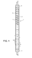
- FIG 1 we see a nuclear fuel rod 1 according to the invention which is shown in its configuration for use in a nuclear reactor, that is to say in a vertical position with the pellets 6 to the lower part as specified below .
- the pencil 1 consists of a sheath 2 of zirconium alloy closed at each of its ends by a cap respectively upper 3 and lower 4.
- the inside of the sheath is essentially divided into two compartments, one of which in the upper part constitutes a gas expansion chamber and the other 6 houses the fissile column formed by the stack of nuclear fuel pellets 6 which each extend in the longitudinal direction XX 'of the pen 1.
- each pellet 6 has substantially the same height H.
- a helical compression spring 7 is housed in the expansion chamber 5 with its lower end bearing against the stack of the pellets 6 and its other end bearing against the top cap 3.
- this spring 7 In addition to maintaining the stack of pellets 6 along the longitudinal axis XX 'and the "absorption" over time of the longitudinal swelling of the pellets 6, the other function of this spring 7 is to prevent the buckling of the section of the sheath on its ovalization mode.
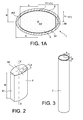
- the Figure 1A shows a straight cross section of pencil 1 of the figure 1 .
- the sheath 2 according to the invention is of constant thickness over its entire periphery and of elliptical general shape. More exactly, the inner wall 200 of the sheath 2 of elliptical shape has a major axis of length 2 * a and a minor axis of length 2 * b.
- the fuel pellet 6 is also elliptical in shape truncated at each end of the major axis of the sheath. In other words, the pellet 6 has a large truncated axis of length 2 * c and a small axis of length 2 * b '.
- the dimension c defines the distance of the truncation plane of the pellet 6 relative to its center.
- a uniform radial play j mounting between the pellet 6 and the sheath 2 is defined on the elliptical sides of the pellet, that is to say over the entire length 2 * c thereof.
- each fuel pellet 6 has a truncated elliptical cross section whose half small axis b 'is of length substantially equal to that of the half minor axis b of the inner wall 200 of sheath 2, to the mounting set near j.
- Free volumes or in other words expansion voids 60 are thus located at both ends of the major truncated axis of the pellet 6, that is to say between the truncated edges 61 of the pellet 6 and the inner wall 200 of the sheath 2.
- the slenderness factor a '/ b' must be at least 1, 5.
- the first targeted application is the specific use of the operating conditions of reactors in the pressurized water (PWR) sector.
- the pencil can then be made of constituent materials that are in principle the same as those used for the design of current standard fuel elements, such as the currently known circular section rods: zirconium alloys or M5 alloy (ZrNbO) for sheaths and pellets of UO 2 ceramic fuel or a mixed mixture based on uranium oxide and reprocessed plutonium oxides.
- zirconium alloys or M5 alloy (ZrNbO) for sheaths and pellets of UO 2 ceramic fuel or a mixed mixture based on uranium oxide and reprocessed plutonium oxides.
- the second intended application is the specific use in operating conditions of gas-cooled fast neutron reactors (RNR-gas), the conditions under which the clad temperatures reached are high in the range of 300 ° C to 900 ° C and the Neutron fluence in fast neutrons is high.
- the pen can then be used in the following constituent materials: refractory metal or semi refractory, such as alloys based on vanadium or ductile ceramic, such as Ti type of MAX-phases 3 SiC 2 to the cladding and pellets ceramic fuel ( U, Pu) C or (U, Pu) O 2 .
- a particular embodiment of a pencil of elliptical section according to the invention is described below.
- the dimensioning of the rod 1 is made to meet the operating conditions of a standard pressurized water reactor (PWR).
- PWR pressurized water reactor
- the elliptical section rod 1 In comparison with the reference geometry of a standard circular section pencil for pressurized water reactor (PWR), the elliptical section rod 1 according to the invention has an increased total section of the order of 4.4% with a surface percentage of fuel in the sheath on the order of 92.5%.
- the total void j, 60 formed respectively by the initial radial clearance to the assembly j between pellets 6 and sheath 2 and the truncations 61 of the ends of the pellet 6 (void space 60 between truncated edges 61 and internal sheath wall 20 ) represents approximately 7.47% of the internal transverse section of the sheath equal to ⁇ * a * b.
- the slenderness a '/ b' considered in the invention equal to 1.8 with the dimensions given above allows to consider the pressing of each pellet no longer along its cylindrical axis XX 'as currently performed for the pencils with circular cross-section, but orthogonally, that is to say in the direction of the minor axis a 'of its elliptical section or in other words on its edge delimited by its height H.
- the elliptical shape of the cladding also makes it possible to envisage the sheathing of the raw pellets of sintering. Indeed, the inventor believes that a pressing of the fuel pellet according to its edge H must ensure a lower dispersion of the thickness dimensions of the sintered pellets by better homogenization of the pressing densities within the pellet.
- the elliptical shape of the sheath must allow cladding of the sheath on the pellet faces (excluding the end voids 60), that is to say on the entire length 2 * c, as soon as the coolant is pressurized.
- the local superheating (at the edges 61) is 136 ° C. with respect to the temperature of the exchange surfaces (at the level of the portions 62) in contact with the sheath.
- the local superheat reaches is 220 ° C.
- This thermal equilibrium that drives the mechanical stability of the section is obtained by optimizing the geometrical parameters of the section: its ovality factor a / b and its truncation ratio c / a. It goes without saying that these parameters depend on each use and their optimization depends on the operating conditions of each fuel pellet and the mechanical properties of the constituent materials, including the laws of behavior in thermal creep and irradiation.
- thermomechanical behavior also results in a control of the internal pressurization of the pencil by the fission gases released by the fuel.
- the presence of the voids 60 at the truncated ends 61 of the pellet constitutes additional expansion tanks with respect to a pencil of standard circular section.
- thermomechanical behavior results in a mechanical interaction between pellets 6 and sheath 2 which flexes the latter.
- Induced bending stresses are located in the end sectors 200 of the sheath next truncations 61 of the fuel pellet.
- the creep of the sheath 2 limits these constraints to a value less than 100 MPa in operation.
- the sheath is thus well solicited only in flexion on its ovalization mode: it does not go into circumferential shrinking mode as is likely to do a pencil sheath with standard circular section.
- the fuel pellet 6 As for the fuel pellet 6, it adapts its section deformations mainly by creeping out towards the end voids 60 under the action of the oval stiffnesses of the truncated elliptic section of the pellet which thus oppose the dilatation and swelling deformities.
Landscapes
- Engineering & Computer Science (AREA)
- Physics & Mathematics (AREA)
- Plasma & Fusion (AREA)
- General Engineering & Computer Science (AREA)
- High Energy & Nuclear Physics (AREA)
- Manufacturing & Machinery (AREA)
- Monitoring And Testing Of Nuclear Reactors (AREA)
Applications Claiming Priority (2)
| Application Number | Priority Date | Filing Date | Title |
|---|---|---|---|
| FR0958661A FR2953637B1 (fr) | 2009-12-04 | 2009-12-04 | Crayon de combustible nucleaire et procede de fabrication de pastilles d'un tel crayon |
| PCT/EP2010/068611 WO2011067274A1 (fr) | 2009-12-04 | 2010-12-01 | Crayon de combustible nucléaire et procédé de fabrication de pastilles d'un tel crayon |
Publications (2)
| Publication Number | Publication Date |
|---|---|
| EP2507796A1 EP2507796A1 (fr) | 2012-10-10 |
| EP2507796B1 true EP2507796B1 (fr) | 2015-01-07 |
Family
ID=42333340
Family Applications (1)
| Application Number | Title | Priority Date | Filing Date |
|---|---|---|---|
| EP10787098.2A Not-in-force EP2507796B1 (fr) | 2009-12-04 | 2010-12-01 | Crayon de combustible nucléaire et procédé de fabrication de pastilles d'un tel crayon |
Country Status (9)
| Country | Link |
|---|---|
| US (1) | US9406410B2 (enExample) |
| EP (1) | EP2507796B1 (enExample) |
| JP (1) | JP5964753B2 (enExample) |
| KR (1) | KR101730058B1 (enExample) |
| CN (1) | CN102770921A (enExample) |
| ES (1) | ES2534470T3 (enExample) |
| FR (1) | FR2953637B1 (enExample) |
| RU (1) | RU2546971C2 (enExample) |
| WO (1) | WO2011067274A1 (enExample) |
Families Citing this family (16)
| Publication number | Priority date | Publication date | Assignee | Title |
|---|---|---|---|---|
| FR3005046B1 (fr) | 2013-04-29 | 2015-05-15 | Commissariat Energie Atomique | Nouveau materiau a base d'uranium, de gadolinium et d'oxygene et son utilisation comme poison neutronique consommable |
| RU2527426C1 (ru) * | 2013-06-28 | 2014-08-27 | Борис Федорович Титов | Твэл ядерного реактора |
| JP6850128B2 (ja) * | 2014-04-14 | 2021-03-31 | アドバンスト・リアクター・コンセプツ・エルエルシー | 合金のマトリックス中に分散したセラミック核燃料 |
| KR102605340B1 (ko) * | 2015-08-27 | 2023-11-23 | 테라파워, 엘엘씨 | 다중 스미어 밀도 연료를 갖는 연료 요소 |
| CN107393688B (zh) * | 2016-05-16 | 2024-06-18 | 深圳市京泉华科技股份有限公司 | 磁芯及具该磁芯的电感装置 |
| CA3078796A1 (en) * | 2017-12-22 | 2019-06-27 | Terrapower, Llc | Annular metal nuclear fuel and methods of manufacturing the same |
| RU2691628C1 (ru) * | 2018-09-03 | 2019-06-17 | Акционерное общество "Высокотехнологический научно-исследовательский институт неорганических материалов имени академика А.А. Бочвара" | Твэл ядерного реактора |
| CN109461509B (zh) * | 2018-09-29 | 2020-11-10 | 中广核研究院有限公司 | 惰性基体弥散燃料芯块及其制备方法 |
| CN109583022B (zh) * | 2018-10-29 | 2020-06-23 | 中广核研究院有限公司 | 燃料棒包壳蠕变有限长管修正方法的建立方法 |
| US11935662B2 (en) * | 2019-07-02 | 2024-03-19 | Westinghouse Electric Company Llc | Elongate SiC fuel elements |
| KR20230079094A (ko) * | 2020-10-07 | 2023-06-05 | 웨스팅하우스 일렉트릭 컴퍼니 엘엘씨 | 내수성 및 증기 산화 저항성이 향상된 코팅 연료 펠릿 |
| CN114188056B (zh) * | 2021-12-03 | 2024-02-20 | 中国原子能科学研究院 | 燃料芯块操作装置及方法 |
| CN114913997B (zh) * | 2022-03-31 | 2024-09-24 | 中广核研究院有限公司 | 控制棒及控制棒组件 |
| CN114752749B (zh) * | 2022-04-18 | 2023-02-28 | 西安交通大学 | 一种提高包壳材料在快中子辐照环境中耐受能力的方法 |
| CN115132379A (zh) * | 2022-07-08 | 2022-09-30 | 中国核动力研究设计院 | 一种采用难熔金属基的弥散微封装棒状燃料元件及反应堆 |
| FR3149720A1 (fr) * | 2023-06-07 | 2024-12-13 | Commissariat A L'energie Atomique Et Aux Energies Alternatives | Crayon de réacteur nucléaire |
Family Cites Families (18)
| Publication number | Priority date | Publication date | Assignee | Title |
|---|---|---|---|---|
| BE580274A (enExample) * | 1958-07-02 | |||
| BE615521A (enExample) * | 1962-03-09 | |||
| GB1271644A (en) | 1968-07-24 | 1972-04-19 | Atomic Energy Authority Uk | Improvements in nuclear fuel elements |
| US3575803A (en) * | 1968-08-08 | 1971-04-20 | Atomic Energy Commission | Reactor fueling method |
| DE2152132A1 (de) * | 1971-10-20 | 1973-04-26 | Siemens Ag | Kernreaktorbrennstab |
| JPS5135884A (enExample) * | 1974-09-20 | 1976-03-26 | Hitachi Ltd | |
| JPS58142293A (ja) | 1982-02-19 | 1983-08-24 | 動力炉・核燃料開発事業団 | 核燃料棒 |
| FR2639463B1 (fr) | 1988-11-22 | 1990-12-21 | Commissariat Energie Atomique | Crayon d'element combustible pour reacteur nucleaire refroidi a l'eau |
| JPH04164291A (ja) | 1990-10-29 | 1992-06-09 | Toshiba Corp | 原子炉用制御棒 |
| JP3726367B2 (ja) * | 1996-08-09 | 2005-12-14 | 三菱マテリアル株式会社 | 軽水炉用燃料棒およびその製造方法 |
| DE19636563C1 (de) | 1996-09-09 | 1998-03-26 | Siemens Ag | Kernreaktor-Brennelemente mit hohem Abbrand und Verfahren zu ihrer Fertigung |
| JPH11202073A (ja) | 1998-01-12 | 1999-07-30 | Toshiba Corp | 核燃料ペレットの製造方法 |
| FR2861888B1 (fr) * | 2003-10-29 | 2008-02-29 | Franco Belge Combustibles | Procede de fabrication de pastilles de combustible nucleaire |
| RU2275700C2 (ru) * | 2004-05-25 | 2006-04-27 | Открытое акционерное общество "Новосибирский завод химконцентратов" | Способ изготовления таблетированного ядерного топлива |
| JP4138763B2 (ja) | 2005-02-28 | 2008-08-27 | 三菱重工業株式会社 | 加圧水型原子炉の燃料集合体及び燃料集合体の設計方法 |
| JP4697938B2 (ja) | 2005-04-04 | 2011-06-08 | 原子燃料工業株式会社 | 高温ガス炉用被覆燃料粒子の製造法 |
| FR2889765B1 (fr) | 2005-08-10 | 2011-06-24 | Commissariat Energie Atomique | Element combustible de type plaque macrostructuree |
| KR100794071B1 (ko) * | 2006-12-05 | 2008-01-10 | 한국원자력연구원 | 핵연료 소결체의 제조 방법 |
-
2009
- 2009-12-04 FR FR0958661A patent/FR2953637B1/fr not_active Expired - Fee Related
-
2010
- 2010-12-01 CN CN2010800631738A patent/CN102770921A/zh active Pending
- 2010-12-01 KR KR1020127017231A patent/KR101730058B1/ko not_active Expired - Fee Related
- 2010-12-01 US US13/513,849 patent/US9406410B2/en not_active Expired - Fee Related
- 2010-12-01 RU RU2012127788/07A patent/RU2546971C2/ru not_active IP Right Cessation
- 2010-12-01 JP JP2012541482A patent/JP5964753B2/ja not_active Expired - Fee Related
- 2010-12-01 EP EP10787098.2A patent/EP2507796B1/fr not_active Not-in-force
- 2010-12-01 WO PCT/EP2010/068611 patent/WO2011067274A1/fr not_active Ceased
- 2010-12-01 ES ES10787098.2T patent/ES2534470T3/es active Active
Also Published As
| Publication number | Publication date |
|---|---|
| CN102770921A (zh) | 2012-11-07 |
| JP5964753B2 (ja) | 2016-08-03 |
| KR101730058B1 (ko) | 2017-05-11 |
| KR20120093410A (ko) | 2012-08-22 |
| RU2012127788A (ru) | 2014-01-10 |
| EP2507796A1 (fr) | 2012-10-10 |
| ES2534470T3 (es) | 2015-04-23 |
| US9406410B2 (en) | 2016-08-02 |
| JP2013513099A (ja) | 2013-04-18 |
| WO2011067274A1 (fr) | 2011-06-09 |
| FR2953637A1 (fr) | 2011-06-10 |
| FR2953637B1 (fr) | 2012-03-23 |
| US20120321031A1 (en) | 2012-12-20 |
| RU2546971C2 (ru) | 2015-04-10 |
Similar Documents
| Publication | Publication Date | Title |
|---|---|---|
| EP2507796B1 (fr) | Crayon de combustible nucléaire et procédé de fabrication de pastilles d'un tel crayon | |
| EP2583282B1 (fr) | Joint d'interface solide a porosite ouverte pour crayon de combustible nucleaire | |
| EP2739465B1 (fr) | Gaine de combustible nucleaire en materiau composite a matrice ceramique et procede de fabrication associe | |
| EP2583284B1 (fr) | Joint d'interface solide a porosite ouverte pour une barre de commande nucleaire | |
| EP1913600B1 (fr) | Element combustible de type plaque macrostructuree | |
| EP1338015B1 (fr) | Crayon comportant un empilement de pastilles de combustible nucleaire oxyde | |
| FR2965969A1 (fr) | Aiguille de combustible nucleaire metallique comprenant une enveloppe avec des fibres de sic | |
| EP3391378B1 (fr) | Grappe absorbante et crayon absorbant pour réacteur nucléaire | |
| TWI795634B (zh) | 自癒液體丸護套間隙熱傳填料 | |
| FR3000594A1 (fr) | Pastille de combustible nucleaire a base de dioxyde d'uranium piegant les produits de fission ayant des microcellules metalliques et sa methode de fabrication | |
| EP0845146B1 (fr) | Crayon absorbant pour grappe de commande de reacteur nucleaire et procede de fabrication | |
| WO2009044061A1 (fr) | Assemblage combustible pour reacteur nucleaire a neutrons rapides | |
| FR3161981A1 (fr) | Pastille de combustible nucléaire intégrant au moins une cavité, dénuée de matière fissile, à section transversale sous la forme d’au moins une portion de spirale non débouchante vers l’extérieur de la pastille, Procédés de fabrication associés. | |
| FR3150632A1 (fr) | Pastille de combustible nucléaire intégrant un insert conducteur thermique sous la forme de branches ramifiées réparties depuis un cylindre intérieur évidé vers l’extérieur de la pastille. | |
| FR2898727A1 (fr) | Barre de combustible nucleaire annulaire pouvant etre regulee en flux de chaleur de tubes interne et externe | |
| CN120390966A (zh) | 具有径向可变富集度的核燃料芯块 | |
| FR3065573A1 (fr) | Cœur de reacteur rapide et procede de chargement de combustible de reacteur rapide | |
| EP4390971A2 (fr) | Réacteur nucléaire à sel(s) fondu(s), de type à neutrons rapides, à cuve remplie de sels liquide inerte autour de la cuve de réacteur en tant que système d`évacuation de la puissance résiduelle du réacteur (epur) | |
| EP0031766B1 (fr) | Crayon de matériau consommable pour le pilotage d'un réacteur nucléaire |
Legal Events
| Date | Code | Title | Description |
|---|---|---|---|
| PUAI | Public reference made under article 153(3) epc to a published international application that has entered the european phase |
Free format text: ORIGINAL CODE: 0009012 |
|
| 17P | Request for examination filed |
Effective date: 20120608 |
|
| AK | Designated contracting states |
Kind code of ref document: A1 Designated state(s): AL AT BE BG CH CY CZ DE DK EE ES FI FR GB GR HR HU IE IS IT LI LT LU LV MC MK MT NL NO PL PT RO RS SE SI SK SM TR |
|
| DAX | Request for extension of the european patent (deleted) | ||
| GRAP | Despatch of communication of intention to grant a patent |
Free format text: ORIGINAL CODE: EPIDOSNIGR1 |
|
| RIC1 | Information provided on ipc code assigned before grant |
Ipc: G21C 3/07 20060101ALN20140702BHEP Ipc: G21C 3/18 20060101ALI20140702BHEP Ipc: G21C 3/62 20060101ALN20140702BHEP Ipc: G21C 3/60 20060101ALN20140702BHEP Ipc: G21C 21/02 20060101ALI20140702BHEP Ipc: G21C 3/06 20060101AFI20140702BHEP |
|
| INTG | Intention to grant announced |
Effective date: 20140725 |
|
| GRAS | Grant fee paid |
Free format text: ORIGINAL CODE: EPIDOSNIGR3 |
|
| GRAA | (expected) grant |
Free format text: ORIGINAL CODE: 0009210 |
|
| AK | Designated contracting states |
Kind code of ref document: B1 Designated state(s): AL AT BE BG CH CY CZ DE DK EE ES FI FR GB GR HR HU IE IS IT LI LT LU LV MC MK MT NL NO PL PT RO RS SE SI SK SM TR |
|
| REG | Reference to a national code |
Ref country code: GB Ref legal event code: FG4D Free format text: NOT ENGLISH |
|
| REG | Reference to a national code |
Ref country code: CH Ref legal event code: EP |
|
| REG | Reference to a national code |
Ref country code: IE Ref legal event code: FG4D Free format text: LANGUAGE OF EP DOCUMENT: FRENCH |
|
| REG | Reference to a national code |
Ref country code: AT Ref legal event code: REF Ref document number: 706221 Country of ref document: AT Kind code of ref document: T Effective date: 20150215 |
|
| REG | Reference to a national code |
Ref country code: DE Ref legal event code: R096 Ref document number: 602010021685 Country of ref document: DE Effective date: 20150219 |
|
| REG | Reference to a national code |
Ref country code: SE Ref legal event code: TRGR |
|
| REG | Reference to a national code |
Ref country code: ES Ref legal event code: FG2A Ref document number: 2534470 Country of ref document: ES Kind code of ref document: T3 Effective date: 20150423 |
|
| REG | Reference to a national code |
Ref country code: NL Ref legal event code: VDEP Effective date: 20150107 |
|
| REG | Reference to a national code |
Ref country code: AT Ref legal event code: MK05 Ref document number: 706221 Country of ref document: AT Kind code of ref document: T Effective date: 20150107 |
|
| REG | Reference to a national code |
Ref country code: LT Ref legal event code: MG4D |
|
| PG25 | Lapsed in a contracting state [announced via postgrant information from national office to epo] |
Ref country code: BG Free format text: LAPSE BECAUSE OF FAILURE TO SUBMIT A TRANSLATION OF THE DESCRIPTION OR TO PAY THE FEE WITHIN THE PRESCRIBED TIME-LIMIT Effective date: 20150407 Ref country code: LT Free format text: LAPSE BECAUSE OF FAILURE TO SUBMIT A TRANSLATION OF THE DESCRIPTION OR TO PAY THE FEE WITHIN THE PRESCRIBED TIME-LIMIT Effective date: 20150107 Ref country code: NO Free format text: LAPSE BECAUSE OF FAILURE TO SUBMIT A TRANSLATION OF THE DESCRIPTION OR TO PAY THE FEE WITHIN THE PRESCRIBED TIME-LIMIT Effective date: 20150407 Ref country code: FI Free format text: LAPSE BECAUSE OF FAILURE TO SUBMIT A TRANSLATION OF THE DESCRIPTION OR TO PAY THE FEE WITHIN THE PRESCRIBED TIME-LIMIT Effective date: 20150107 Ref country code: HR Free format text: LAPSE BECAUSE OF FAILURE TO SUBMIT A TRANSLATION OF THE DESCRIPTION OR TO PAY THE FEE WITHIN THE PRESCRIBED TIME-LIMIT Effective date: 20150107 |
|
| PG25 | Lapsed in a contracting state [announced via postgrant information from national office to epo] |
Ref country code: GR Free format text: LAPSE BECAUSE OF FAILURE TO SUBMIT A TRANSLATION OF THE DESCRIPTION OR TO PAY THE FEE WITHIN THE PRESCRIBED TIME-LIMIT Effective date: 20150408 Ref country code: PL Free format text: LAPSE BECAUSE OF FAILURE TO SUBMIT A TRANSLATION OF THE DESCRIPTION OR TO PAY THE FEE WITHIN THE PRESCRIBED TIME-LIMIT Effective date: 20150107 Ref country code: AT Free format text: LAPSE BECAUSE OF FAILURE TO SUBMIT A TRANSLATION OF THE DESCRIPTION OR TO PAY THE FEE WITHIN THE PRESCRIBED TIME-LIMIT Effective date: 20150107 Ref country code: RS Free format text: LAPSE BECAUSE OF FAILURE TO SUBMIT A TRANSLATION OF THE DESCRIPTION OR TO PAY THE FEE WITHIN THE PRESCRIBED TIME-LIMIT Effective date: 20150107 Ref country code: NL Free format text: LAPSE BECAUSE OF FAILURE TO SUBMIT A TRANSLATION OF THE DESCRIPTION OR TO PAY THE FEE WITHIN THE PRESCRIBED TIME-LIMIT Effective date: 20150107 Ref country code: IS Free format text: LAPSE BECAUSE OF FAILURE TO SUBMIT A TRANSLATION OF THE DESCRIPTION OR TO PAY THE FEE WITHIN THE PRESCRIBED TIME-LIMIT Effective date: 20150507 Ref country code: LV Free format text: LAPSE BECAUSE OF FAILURE TO SUBMIT A TRANSLATION OF THE DESCRIPTION OR TO PAY THE FEE WITHIN THE PRESCRIBED TIME-LIMIT Effective date: 20150107 |
|
| REG | Reference to a national code |
Ref country code: DE Ref legal event code: R097 Ref document number: 602010021685 Country of ref document: DE |
|
| PG25 | Lapsed in a contracting state [announced via postgrant information from national office to epo] |
Ref country code: DK Free format text: LAPSE BECAUSE OF FAILURE TO SUBMIT A TRANSLATION OF THE DESCRIPTION OR TO PAY THE FEE WITHIN THE PRESCRIBED TIME-LIMIT Effective date: 20150107 Ref country code: EE Free format text: LAPSE BECAUSE OF FAILURE TO SUBMIT A TRANSLATION OF THE DESCRIPTION OR TO PAY THE FEE WITHIN THE PRESCRIBED TIME-LIMIT Effective date: 20150107 Ref country code: SK Free format text: LAPSE BECAUSE OF FAILURE TO SUBMIT A TRANSLATION OF THE DESCRIPTION OR TO PAY THE FEE WITHIN THE PRESCRIBED TIME-LIMIT Effective date: 20150107 Ref country code: RO Free format text: LAPSE BECAUSE OF FAILURE TO SUBMIT A TRANSLATION OF THE DESCRIPTION OR TO PAY THE FEE WITHIN THE PRESCRIBED TIME-LIMIT Effective date: 20150107 Ref country code: CZ Free format text: LAPSE BECAUSE OF FAILURE TO SUBMIT A TRANSLATION OF THE DESCRIPTION OR TO PAY THE FEE WITHIN THE PRESCRIBED TIME-LIMIT Effective date: 20150107 |
|
| PLBE | No opposition filed within time limit |
Free format text: ORIGINAL CODE: 0009261 |
|
| STAA | Information on the status of an ep patent application or granted ep patent |
Free format text: STATUS: NO OPPOSITION FILED WITHIN TIME LIMIT |
|
| 26N | No opposition filed |
Effective date: 20151008 |
|
| PG25 | Lapsed in a contracting state [announced via postgrant information from national office to epo] |
Ref country code: IT Free format text: LAPSE BECAUSE OF FAILURE TO SUBMIT A TRANSLATION OF THE DESCRIPTION OR TO PAY THE FEE WITHIN THE PRESCRIBED TIME-LIMIT Effective date: 20150107 |
|
| REG | Reference to a national code |
Ref country code: FR Ref legal event code: PLFP Year of fee payment: 6 |
|
| PG25 | Lapsed in a contracting state [announced via postgrant information from national office to epo] |
Ref country code: SI Free format text: LAPSE BECAUSE OF FAILURE TO SUBMIT A TRANSLATION OF THE DESCRIPTION OR TO PAY THE FEE WITHIN THE PRESCRIBED TIME-LIMIT Effective date: 20150107 |
|
| PG25 | Lapsed in a contracting state [announced via postgrant information from national office to epo] |
Ref country code: MC Free format text: LAPSE BECAUSE OF FAILURE TO SUBMIT A TRANSLATION OF THE DESCRIPTION OR TO PAY THE FEE WITHIN THE PRESCRIBED TIME-LIMIT Effective date: 20150107 Ref country code: LU Free format text: LAPSE BECAUSE OF FAILURE TO SUBMIT A TRANSLATION OF THE DESCRIPTION OR TO PAY THE FEE WITHIN THE PRESCRIBED TIME-LIMIT Effective date: 20151201 |
|
| REG | Reference to a national code |
Ref country code: CH Ref legal event code: PL |
|
| REG | Reference to a national code |
Ref country code: IE Ref legal event code: MM4A |
|
| PG25 | Lapsed in a contracting state [announced via postgrant information from national office to epo] |
Ref country code: IE Free format text: LAPSE BECAUSE OF NON-PAYMENT OF DUE FEES Effective date: 20151201 Ref country code: CH Free format text: LAPSE BECAUSE OF NON-PAYMENT OF DUE FEES Effective date: 20151231 Ref country code: LI Free format text: LAPSE BECAUSE OF NON-PAYMENT OF DUE FEES Effective date: 20151231 |
|
| REG | Reference to a national code |
Ref country code: FR Ref legal event code: PLFP Year of fee payment: 7 |
|
| PG25 | Lapsed in a contracting state [announced via postgrant information from national office to epo] |
Ref country code: HU Free format text: LAPSE BECAUSE OF FAILURE TO SUBMIT A TRANSLATION OF THE DESCRIPTION OR TO PAY THE FEE WITHIN THE PRESCRIBED TIME-LIMIT; INVALID AB INITIO Effective date: 20101201 Ref country code: SM Free format text: LAPSE BECAUSE OF FAILURE TO SUBMIT A TRANSLATION OF THE DESCRIPTION OR TO PAY THE FEE WITHIN THE PRESCRIBED TIME-LIMIT Effective date: 20150107 |
|
| PG25 | Lapsed in a contracting state [announced via postgrant information from national office to epo] |
Ref country code: CY Free format text: LAPSE BECAUSE OF FAILURE TO SUBMIT A TRANSLATION OF THE DESCRIPTION OR TO PAY THE FEE WITHIN THE PRESCRIBED TIME-LIMIT Effective date: 20150107 |
|
| PG25 | Lapsed in a contracting state [announced via postgrant information from national office to epo] |
Ref country code: MT Free format text: LAPSE BECAUSE OF FAILURE TO SUBMIT A TRANSLATION OF THE DESCRIPTION OR TO PAY THE FEE WITHIN THE PRESCRIBED TIME-LIMIT Effective date: 20150107 |
|
| REG | Reference to a national code |
Ref country code: FR Ref legal event code: PLFP Year of fee payment: 8 |
|
| PGFP | Annual fee paid to national office [announced via postgrant information from national office to epo] |
Ref country code: DE Payment date: 20171212 Year of fee payment: 8 |
|
| PGFP | Annual fee paid to national office [announced via postgrant information from national office to epo] |
Ref country code: GB Payment date: 20171219 Year of fee payment: 8 Ref country code: SE Payment date: 20171211 Year of fee payment: 8 Ref country code: BE Payment date: 20171220 Year of fee payment: 8 |
|
| PGFP | Annual fee paid to national office [announced via postgrant information from national office to epo] |
Ref country code: ES Payment date: 20180129 Year of fee payment: 8 |
|
| PGFP | Annual fee paid to national office [announced via postgrant information from national office to epo] |
Ref country code: FR Payment date: 20180102 Year of fee payment: 8 |
|
| PG25 | Lapsed in a contracting state [announced via postgrant information from national office to epo] |
Ref country code: PT Free format text: LAPSE BECAUSE OF FAILURE TO SUBMIT A TRANSLATION OF THE DESCRIPTION OR TO PAY THE FEE WITHIN THE PRESCRIBED TIME-LIMIT Effective date: 20150107 Ref country code: TR Free format text: LAPSE BECAUSE OF FAILURE TO SUBMIT A TRANSLATION OF THE DESCRIPTION OR TO PAY THE FEE WITHIN THE PRESCRIBED TIME-LIMIT Effective date: 20150107 Ref country code: MK Free format text: LAPSE BECAUSE OF FAILURE TO SUBMIT A TRANSLATION OF THE DESCRIPTION OR TO PAY THE FEE WITHIN THE PRESCRIBED TIME-LIMIT Effective date: 20150107 |
|
| PG25 | Lapsed in a contracting state [announced via postgrant information from national office to epo] |
Ref country code: AL Free format text: LAPSE BECAUSE OF FAILURE TO SUBMIT A TRANSLATION OF THE DESCRIPTION OR TO PAY THE FEE WITHIN THE PRESCRIBED TIME-LIMIT Effective date: 20150107 |
|
| REG | Reference to a national code |
Ref country code: DE Ref legal event code: R119 Ref document number: 602010021685 Country of ref document: DE |
|
| REG | Reference to a national code |
Ref country code: SE Ref legal event code: EUG |
|
| PG25 | Lapsed in a contracting state [announced via postgrant information from national office to epo] |
Ref country code: SE Free format text: LAPSE BECAUSE OF NON-PAYMENT OF DUE FEES Effective date: 20181202 |
|
| GBPC | Gb: european patent ceased through non-payment of renewal fee |
Effective date: 20181201 |
|
| REG | Reference to a national code |
Ref country code: BE Ref legal event code: MM Effective date: 20181231 |
|
| PG25 | Lapsed in a contracting state [announced via postgrant information from national office to epo] |
Ref country code: FR Free format text: LAPSE BECAUSE OF NON-PAYMENT OF DUE FEES Effective date: 20181231 Ref country code: DE Free format text: LAPSE BECAUSE OF NON-PAYMENT OF DUE FEES Effective date: 20190702 |
|
| PG25 | Lapsed in a contracting state [announced via postgrant information from national office to epo] |
Ref country code: BE Free format text: LAPSE BECAUSE OF NON-PAYMENT OF DUE FEES Effective date: 20181231 |
|
| PG25 | Lapsed in a contracting state [announced via postgrant information from national office to epo] |
Ref country code: GB Free format text: LAPSE BECAUSE OF NON-PAYMENT OF DUE FEES Effective date: 20181201 |
|
| REG | Reference to a national code |
Ref country code: ES Ref legal event code: FD2A Effective date: 20200131 |
|
| PG25 | Lapsed in a contracting state [announced via postgrant information from national office to epo] |
Ref country code: ES Free format text: LAPSE BECAUSE OF NON-PAYMENT OF DUE FEES Effective date: 20181202 |