EP2507436B1 - Snow groomer and relative control method - Google Patents
Snow groomer and relative control method Download PDFInfo
- Publication number
- EP2507436B1 EP2507436B1 EP20100807540 EP10807540A EP2507436B1 EP 2507436 B1 EP2507436 B1 EP 2507436B1 EP 20100807540 EP20100807540 EP 20100807540 EP 10807540 A EP10807540 A EP 10807540A EP 2507436 B1 EP2507436 B1 EP 2507436B1
- Authority
- EP
- European Patent Office
- Prior art keywords
- flow rate
- total flow
- rate demand
- snow groomer
- control system
- Prior art date
- Legal status (The legal status is an assumption and is not a legal conclusion. Google has not performed a legal analysis and makes no representation as to the accuracy of the status listed.)
- Active
Links
- 238000000034 method Methods 0.000 title claims description 16
- 230000000712 assembly Effects 0.000 claims description 8
- 238000000429 assembly Methods 0.000 claims description 8
- 230000001276 controlling effect Effects 0.000 description 10
- 238000002485 combustion reaction Methods 0.000 description 9
- 230000001105 regulatory effect Effects 0.000 description 4
- 238000005265 energy consumption Methods 0.000 description 3
- 230000003370 grooming effect Effects 0.000 description 2
- 238000010276 construction Methods 0.000 description 1
- 239000012530 fluid Substances 0.000 description 1
- 230000001681 protective effect Effects 0.000 description 1
Images

Classifications
-
- E—FIXED CONSTRUCTIONS
- E01—CONSTRUCTION OF ROADS, RAILWAYS, OR BRIDGES
- E01H—STREET CLEANING; CLEANING OF PERMANENT WAYS; CLEANING BEACHES; DISPERSING OR PREVENTING FOG IN GENERAL CLEANING STREET OR RAILWAY FURNITURE OR TUNNEL WALLS
- E01H4/00—Working on surfaces of snow or ice in order to make them suitable for traffic or sporting purposes, e.g. by compacting snow
- E01H4/02—Working on surfaces of snow or ice in order to make them suitable for traffic or sporting purposes, e.g. by compacting snow for sporting purposes, e.g. preparation of ski trails; Construction of artificial surfacings for snow or ice sports ; Trails specially adapted for on-the-snow vehicles, e.g. devices adapted for ski-trails
-
- B—PERFORMING OPERATIONS; TRANSPORTING
- B62—LAND VEHICLES FOR TRAVELLING OTHERWISE THAN ON RAILS
- B62D—MOTOR VEHICLES; TRAILERS
- B62D55/00—Endless track vehicles
-
- B—PERFORMING OPERATIONS; TRANSPORTING
- B62—LAND VEHICLES FOR TRAVELLING OTHERWISE THAN ON RAILS
- B62D—MOTOR VEHICLES; TRAILERS
- B62D55/00—Endless track vehicles
- B62D55/02—Endless track vehicles with tracks and additional ground wheels
-
- E—FIXED CONSTRUCTIONS
- E02—HYDRAULIC ENGINEERING; FOUNDATIONS; SOIL SHIFTING
- E02F—DREDGING; SOIL-SHIFTING
- E02F9/00—Component parts of dredgers or soil-shifting machines, not restricted to one of the kinds covered by groups E02F3/00 - E02F7/00
- E02F9/20—Drives; Control devices
- E02F9/22—Hydraulic or pneumatic drives
- E02F9/2221—Control of flow rate; Load sensing arrangements
- E02F9/2232—Control of flow rate; Load sensing arrangements using one or more variable displacement pumps
- E02F9/2235—Control of flow rate; Load sensing arrangements using one or more variable displacement pumps including an electronic controller
-
- E—FIXED CONSTRUCTIONS
- E02—HYDRAULIC ENGINEERING; FOUNDATIONS; SOIL SHIFTING
- E02F—DREDGING; SOIL-SHIFTING
- E02F9/00—Component parts of dredgers or soil-shifting machines, not restricted to one of the kinds covered by groups E02F3/00 - E02F7/00
- E02F9/20—Drives; Control devices
- E02F9/22—Hydraulic or pneumatic drives
- E02F9/2278—Hydraulic circuits
- E02F9/2296—Systems with a variable displacement pump
Definitions
- the present invention relates to a snow groomer for grooming ski slopes.
- the present invention relates to a snow groomer comprising a frame; at least one attachment connected movably to the frame; at least one hydraulic assembly comprising at least one actuator for positioning the attachment with respect to the frame, and at least one valve for controlling the actuator; and a pump for supplying the hydraulic assembly.
- the snow groomer normally comprises a hydraulic control device connected to the pump; lines connecting the pump to the attachment hydraulic assembly; and an internal combustion engine connected to and for driving the pump.
- the pump is controlled by the hydraulic control device as follows.
- the hydraulic control device acts on the pump to deliver the maximum possible flow rate, which varies depending on the operating conditions, in particular the speed, of the internal combustion engine.
- the pump delivers the maximum flow rate, even if the actuator does not need it; in which case, the valve delivers the necessary flow rate to the actuator, and the difference between the maximum flow rate from the pump and the necessary flow rate is drained into a holding tank.
- Another drawback of the known art lies in unnecessary operation of the pump, which consists in the valves draining surplus flow into the holding tank, and which subtracts energy from other groomer user devices.
- Another object of the present invention is to provide a snow groomer designed to reduce energy consumption.
- Another object of the present invention is to reduce the degree of unnecessary operation, i.e. reduce the amount of flow drained into the holding tank.
- a snow groomer comprising a frame; at least one attachment connected movably to the frame; and at least one hydraulic assembly comprising at least one actuator for positioning the attachment with respect to the frame, and at least one valve for controlling the actuator;
- the snow groomer being characterized by comprising a variable-flow pump for supplying the hydraulic assembly; and a control system for calculating a total flow rate demand of the hydraulic assembly, and controlling the variable-flow pump as a function of the total flow rate demand, so delivery of the variable-flow pump preferably equals the total flow rate demand.
- variable-flow pump is able to deliver a total flow rate that takes into account total flow rate demand, and so reduce energy consumption of the groomer.
- Another object of the present invention is to provide a method of controlling a snow groomer, designed to eliminate the drawbacks of the known art.
- a method of controlling a snow groomer comprising the steps of:
- Number 1 in Figure 1 indicates as a whole a snow groomer for grooming ski slopes, and which comprises a frame 2; an internal combustion engine 3; two independent tracks 4 and 5; two drive wheels 6 and 7 connected to respective tracks 4 and 5; a plurality of attachments 8; a hydraulic drive 9 for powering drive wheel 6; a hydraulic drive 10 for powering drive wheel 7; a hydraulic drive 11 for powering a component 12; and a hydraulic drive 13 for positioning attachments 8.
- attachments 8 comprise a shovel connected movably to frame 2; a tiller also connected movably to frame 2; and possibly a winch (not shown) connected movably to frame 2.
- Each of the accessories 8 described can assume a plurality of positions with respect to frame 2, and which are controlled by hydraulic drive 13.
- the tiller is equipped with the component 12 - in the example shown, a rotary shaft - which is driven directly by dedicated hydraulic drive 11.
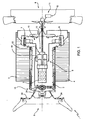
- hydraulic drive 13 comprises a variable-flow pump 14; a hydraulic assembly 15; a tank 16; a pressure sensor 17; a control valve 18; a delivery branch 19; and a return branch 20.
- Snow groomer 1 also comprises a control system 21 for controlling hydraulic drive 13.
- Variable-flow pump 14 is powered by internal combustion engine 3 via a drive shaft 22, is designed to deliver a maximum flow rate as a function of the speed of internal combustion engine 3, and comprises a regulating device 23 for adjusting delivery between a minimum and maximum flow rate, regardless of the speed of internal combustion engine 3.
- variable-flow pump 14 is a variable-eccentricity vane pump, in which regulating device 23 adjusts the eccentricity of the vanes as a function of a regulating signal from control system 21.
- Hydraulic assembly 15 in Figure 2 is associated with only one attachment 8, e.g. the shovel, and comprises, for example, four actuators 24 - in the example shown, double-acting hydraulic cylinders - for positioning attachment 8; and four valves 25 - in the example shown, four-way, three-position slide valves - for controlling actuators 24.
- Each valve 25 is associated with a respective actuator 24, and comprises a servocontrol 26, and a block 27 for controlling valve 25 and servocontrol 26.
- Block 27 of valve 25 is designed to determine the flow rate between valve 25 and respective actuator 24, and to control valve 25 by means of servocontrol 26.
- Pressure sensor 17 monitors the difference in pressure between delivery branch 19 and return branch 20, and controls control valve 18 to drain fluid into tank 16 when the pressure difference exceeds a given threshold value. This is a precautionary measure to prevent a dangerous build-up in pressure along delivery branch 19.
- Control system 21 comprises a control unit 28; a control member 29, normally a joystick; a selector 30; and a speed sensor 31.
- Control unit 28 is connected to internal combustion engine 3 to acquire the speed of internal combustion engine 3; and to blocks 27 of valves 25 to sense the flow rates from valves 25 to actuators 24 and to control servocontrols 26.
- each hydraulic assembly comprises only one actuator and one valve.
- control system 21 controls operation of snow groomer 1, as regards use of attachments 8, to optimize energy consumption of groomer 1. More specifically, control system 21 controls positioning of attachments 8 with respect to frame 2; calculates a total flow rate demand of hydraulic assemblies 15; and controls delivery from variable-flow pump 14 accordingly. In a preferred embodiment of the present invention, control system 21 controls variable-flow pump 14 so that the delivery from variable-flow pump 14 substantially, and in fact, equals total flow rate demand.
- Control system 21 determines the flow rates between valves 25 and actuators 24 by means of blocks 27; and, by means of control unit 28, accordingly calculates the total flow rate demand of hydraulic assemblies 15.
- Attachments 8 are operator-controlled using control member 29, which supplies control unit 28 with a control signal related to, in fact indicating, the desired flow rates between valves 25 and actuators 24; and control unit 28 calculates the total flow rate demand of hydraulic assemblies 15 as a function of the control signals related to the desired flow rates.
- Control member 29 in the example shown is a joystick, which can assume a plurality of operating positions within a given range; and the control signal indicating the desired flow rates between valves 25 and actuators 24 depends on the operating position of control member 29. In other words, control member 29 regulates the desired flow rates and, therefore, the operating speed of actuators 24 within a given operating speed range.
- control system 21 acquires the sensed and desired flow rates at a given instant; and immediately determines the total flow rate demand accordingly, to carry out the operator-requested operations.
- control unit calculates total flow rate demand on the basis of the desired flow rates only, and more specifically as substantially the sum of the desired flow rates.
- control unit calculates total flow rate demand on the basis of the sensed flow rates only, and more specifically as substantially the sum of the sensed flow rates.
- At least one of the operating speed range limits can be adjusted by the operator using selector 30, which, in a preferred embodiment, reduces total flow rate demand by a given percentage. That is, selector 30 reduces each desired flow rate so that the reduction is not made at the expense of the actuator 24 with the higher resistive load. For example, each desired flow rate is reduced by the same percentage.
- total flow rate demand varies with the travelling speed of snow groomer 1.
- total flow rate demand increases alongside an increase in travelling speed, so that the operating speed of the attachments is related to travelling speed.
- control system 21 senses the travelling speed of snow groomer 1, and recalculates the total flow rate demand of hydraulic assembly 15, e.g. recalculates the desired flow rates, accordingly.
- Variable-flow pump 14 is actually characterized by a maximum delivery, which depends on its construction and dimensional characteristics and its operating speed. In the example shown, the operating speed of variable-flow pump 14 is related to the speed of internal combustion engine 3.
- Control unit 28 acquires the operating speed of variable-flow pump 14 to determine its maximum delivery.
- Control unit 28 compares the total flow rate demand with the maximum delivery, and, if total flow rate demand exceeds maximum delivery, recalculates total flow rate demand to equal maximum delivery, by reducing the desired flow rate of each actuator 24 so that the reduction is not made at the expense of the actuator 24 with the higher resistive load. For example, each desired flow rate is reduced by the same percentage.
- control member is connected directly to the valves, as opposed to the control unit, and acts directly on the valves to regulate the desired flow rate.
- the control unit senses the delivery from the valves, and calculates total flow rate demand accordingly. More specifically, total flow rate demand is substantially equal to the total sensed delivery, and may be recalculated on the basis of the travelling speed of the groomer, the operator selector settings, and the maximum delivery of the variable-flow pump, as in the previous embodiment.
- variable-flow pump 14 can be regulated in three ways :
Landscapes
- Engineering & Computer Science (AREA)
- Civil Engineering (AREA)
- Structural Engineering (AREA)
- General Engineering & Computer Science (AREA)
- Mining & Mineral Resources (AREA)
- Combustion & Propulsion (AREA)
- Chemical & Material Sciences (AREA)
- Transportation (AREA)
- Mechanical Engineering (AREA)
- Architecture (AREA)
- Physics & Mathematics (AREA)
- Fluid Mechanics (AREA)
- Fluid-Pressure Circuits (AREA)
- Preparation Of Compounds By Using Micro-Organisms (AREA)
- Automobile Manufacture Line, Endless Track Vehicle, Trailer (AREA)
Applications Claiming Priority (2)
| Application Number | Priority Date | Filing Date | Title |
|---|---|---|---|
| ITMI2009A002119A IT1397194B1 (it) | 2009-12-01 | 2009-12-01 | Veicolo battipista e relativo metodo di controllo. |
| PCT/IB2010/003062 WO2011067651A2 (en) | 2009-12-01 | 2010-11-30 | Snow groomer and relative control method |
Publications (2)
| Publication Number | Publication Date |
|---|---|
| EP2507436A2 EP2507436A2 (en) | 2012-10-10 |
| EP2507436B1 true EP2507436B1 (en) | 2015-05-06 |
Family
ID=42269431
Family Applications (1)
| Application Number | Title | Priority Date | Filing Date |
|---|---|---|---|
| EP20100807540 Active EP2507436B1 (en) | 2009-12-01 | 2010-11-30 | Snow groomer and relative control method |
Country Status (5)
| Country | Link |
|---|---|
| US (1) | US10329725B2 (it) |
| EP (1) | EP2507436B1 (it) |
| CA (1) | CA2782190C (it) |
| IT (1) | IT1397194B1 (it) |
| WO (1) | WO2011067651A2 (it) |
Families Citing this family (5)
| Publication number | Priority date | Publication date | Assignee | Title |
|---|---|---|---|---|
| USD745557S1 (en) * | 2013-10-15 | 2015-12-15 | Deere & Company | Display screen or portion thereof with icon |
| ITUA20162397A1 (it) * | 2016-04-07 | 2017-10-07 | Prinoth Spa | Apparato idraulico per alimentare un gruppo di dispositivi tracciatori per un veicolo cingolato; il gruppo di dispositivi tracciatori e il veicolo cingolato |
| USD845353S1 (en) * | 2016-04-11 | 2019-04-09 | Prinoth S.P.A. | Snow groomer |
| IT201700055909A1 (it) * | 2017-05-23 | 2018-11-23 | Prinoth Spa | Ruota motrice e sistema di trazione per un veicolo cingolato |
| DE102022203981A1 (de) * | 2022-04-25 | 2023-10-26 | Kässbohrer Geländefahrzeug Aktiengesellschaft | Pistenraupe zur Gestaltung und Pflege von Schneegelände |
Family Cites Families (13)
| Publication number | Priority date | Publication date | Assignee | Title |
|---|---|---|---|---|
| DE3416246C1 (de) * | 1984-05-02 | 1985-10-24 | Ski-Data Computer-Handelsgesellschaft mbH, St. Leonhard, Grödig | Vorrichtung zur Steuerung der Bewegungen der Planierwerkzeuge von Pistenpraeparierfahrzeugen |
| US4739616A (en) * | 1985-12-13 | 1988-04-26 | Sundstrand Corporation | Summing pressure compensation control |
| JPH04210101A (ja) * | 1990-11-30 | 1992-07-31 | Komatsu Ltd | 油圧回路 |
| US5142800A (en) * | 1991-12-27 | 1992-09-01 | Logan Manufacturing Company | Snow groomer tow frame alignment device |
| JP3511453B2 (ja) * | 1997-10-08 | 2004-03-29 | 日立建機株式会社 | 油圧建設機械の原動機と油圧ポンプの制御装置 |
| CA2256172A1 (en) * | 1998-12-15 | 2000-06-15 | Bombardier Inc. | Multifunction joystick |
| US7007466B2 (en) * | 2001-12-21 | 2006-03-07 | Caterpillar Inc. | System and method for controlling hydraulic flow |
| DE10253412A1 (de) * | 2002-11-08 | 2004-05-27 | Kässbohrer Geländefahrzeug AG | Verfahren zur Steuerung eines Pistenpflegefahrzeugs und Pistenpflegefahrzeug |
| US7630793B2 (en) * | 2004-12-10 | 2009-12-08 | Caterpillar S.A.R.L. | Method of altering operation of work machine based on work tool performance footprint to maintain desired relationship between operational characteristics of work tool and work machine |
| DE102005046914A1 (de) * | 2005-09-30 | 2007-04-05 | Bomag Gmbh | Gerät zur Schneeflächenpräparierung und Verfahren zur Steuerung eines Hydraulikkreislaufs zwischen einem solchem Gerät und einer Zugmaschine |
| CA2530727A1 (en) * | 2005-12-16 | 2007-06-16 | Richard Hacker | Load sensing hydraulic system for plow/spreader vehicles |
| US7729833B2 (en) * | 2006-09-11 | 2010-06-01 | Caterpillar Inc. | Implement control system based on input position and velocity |
| ITMI20070188U1 (it) * | 2007-05-25 | 2008-11-26 | Rolic Invest Sarl | Veicolo battipista |
-
2009
- 2009-12-01 IT ITMI2009A002119A patent/IT1397194B1/it active
-
2010
- 2010-11-30 WO PCT/IB2010/003062 patent/WO2011067651A2/en active Application Filing
- 2010-11-30 US US13/512,714 patent/US10329725B2/en active Active
- 2010-11-30 CA CA2782190A patent/CA2782190C/en active Active
- 2010-11-30 EP EP20100807540 patent/EP2507436B1/en active Active
Also Published As
| Publication number | Publication date |
|---|---|
| CA2782190C (en) | 2018-02-20 |
| US20130138304A1 (en) | 2013-05-30 |
| EP2507436A2 (en) | 2012-10-10 |
| CA2782190A1 (en) | 2011-06-09 |
| WO2011067651A3 (en) | 2011-08-04 |
| WO2011067651A2 (en) | 2011-06-09 |
| IT1397194B1 (it) | 2013-01-04 |
| ITMI20092119A1 (it) | 2011-06-02 |
| US10329725B2 (en) | 2019-06-25 |
Similar Documents
| Publication | Publication Date | Title |
|---|---|---|
| EP2507436B1 (en) | Snow groomer and relative control method | |
| US10584722B2 (en) | Hydraulic fluid energy regeneration apparatus of work machine | |
| EP3203089B1 (en) | Workmachine comprising a hydraulic drive system | |
| US10280593B2 (en) | Hydraulic fluid energy regeneration device for work machine | |
| US9345191B2 (en) | Self-propelled harvesting machine having a vertically controlled header | |
| EP2910795B1 (en) | Work machine | |
| US9334881B2 (en) | Industrial vehicle | |
| EP2520152B1 (en) | Header height control with closed center pump | |
| WO2010075212A2 (en) | Hydraulic control system utilizing feed-foward control | |
| JP2015086959A (ja) | 建設機械の油圧駆動システム | |
| EP3591241B1 (en) | Work machine | |
| EP0772729B1 (en) | Arrangement in a hydraulically operated rock drilling equipment | |
| JP4715400B2 (ja) | 建設機械の油圧制御装置 | |
| EP3683453B1 (en) | Driving device of construction equipment | |
| CN114127369B (zh) | 挖土机 | |
| US20040003782A1 (en) | Method and device for regulation of a cooling fan drive on an internal combustion engine in a construction or working machine | |
| JP2009167659A (ja) | 作業機械の油圧制御回路 | |
| JP5503198B2 (ja) | 作業機の油圧装置 | |
| EP3617563B1 (en) | Traveling control mechanism and traveling control method of hydraulic driving type construction machine | |
| JP2008075365A (ja) | 作業機械における制御システム | |
| EP4056765B1 (en) | Hydraulic system for a construction machine | |
| US20230099135A1 (en) | Construction Machine | |
| KR101568047B1 (ko) | 굴삭기의 암과 버킷의 유압회로 | |
| CA2416037A1 (en) | Hydraulic system for a working machine that comprises a special consumer | |
| CN115111233A (zh) | 液压压力介质供应装置、利用液压压力介质供应装置的方法和移动式作业机器 |
Legal Events
| Date | Code | Title | Description |
|---|---|---|---|
| PUAI | Public reference made under article 153(3) epc to a published international application that has entered the european phase |
Free format text: ORIGINAL CODE: 0009012 |
|
| 17P | Request for examination filed |
Effective date: 20120618 |
|
| AK | Designated contracting states |
Kind code of ref document: A2 Designated state(s): AL AT BE BG CH CY CZ DE DK EE ES FI FR GB GR HR HU IE IS IT LI LT LU LV MC MK MT NL NO PL PT RO RS SE SI SK SM TR |
|
| DAX | Request for extension of the european patent (deleted) | ||
| RAP1 | Party data changed (applicant data changed or rights of an application transferred) |
Owner name: SNOWGROLIC S.A R.L. |
|
| GRAP | Despatch of communication of intention to grant a patent |
Free format text: ORIGINAL CODE: EPIDOSNIGR1 |
|
| INTG | Intention to grant announced |
Effective date: 20141128 |
|
| GRAS | Grant fee paid |
Free format text: ORIGINAL CODE: EPIDOSNIGR3 |
|
| GRAA | (expected) grant |
Free format text: ORIGINAL CODE: 0009210 |
|
| AK | Designated contracting states |
Kind code of ref document: B1 Designated state(s): AL AT BE BG CH CY CZ DE DK EE ES FI FR GB GR HR HU IE IS IT LI LT LU LV MC MK MT NL NO PL PT RO RS SE SI SK SM TR |
|
| REG | Reference to a national code |
Ref country code: GB Ref legal event code: FG4D |
|
| REG | Reference to a national code |
Ref country code: CH Ref legal event code: EP |
|
| REG | Reference to a national code |
Ref country code: IE Ref legal event code: FG4D |
|
| REG | Reference to a national code |
Ref country code: AT Ref legal event code: REF Ref document number: 725805 Country of ref document: AT Kind code of ref document: T Effective date: 20150615 |
|
| REG | Reference to a national code |
Ref country code: DE Ref legal event code: R096 Ref document number: 602010024562 Country of ref document: DE Effective date: 20150618 |
|
| REG | Reference to a national code |
Ref country code: CH Ref legal event code: NV Representative=s name: HEPP WENGER RYFFEL AG, CH |
|
| REG | Reference to a national code |
Ref country code: NL Ref legal event code: MP Effective date: 20150506 |
|
| REG | Reference to a national code |
Ref country code: FR Ref legal event code: PLFP Year of fee payment: 6 |
|
| REG | Reference to a national code |
Ref country code: LT Ref legal event code: MG4D |
|
| PG25 | Lapsed in a contracting state [announced via postgrant information from national office to epo] |
Ref country code: ES Free format text: LAPSE BECAUSE OF FAILURE TO SUBMIT A TRANSLATION OF THE DESCRIPTION OR TO PAY THE FEE WITHIN THE PRESCRIBED TIME-LIMIT Effective date: 20150506 Ref country code: PT Free format text: LAPSE BECAUSE OF FAILURE TO SUBMIT A TRANSLATION OF THE DESCRIPTION OR TO PAY THE FEE WITHIN THE PRESCRIBED TIME-LIMIT Effective date: 20150907 Ref country code: NO Free format text: LAPSE BECAUSE OF FAILURE TO SUBMIT A TRANSLATION OF THE DESCRIPTION OR TO PAY THE FEE WITHIN THE PRESCRIBED TIME-LIMIT Effective date: 20150806 Ref country code: LT Free format text: LAPSE BECAUSE OF FAILURE TO SUBMIT A TRANSLATION OF THE DESCRIPTION OR TO PAY THE FEE WITHIN THE PRESCRIBED TIME-LIMIT Effective date: 20150506 Ref country code: HR Free format text: LAPSE BECAUSE OF FAILURE TO SUBMIT A TRANSLATION OF THE DESCRIPTION OR TO PAY THE FEE WITHIN THE PRESCRIBED TIME-LIMIT Effective date: 20150506 Ref country code: FI Free format text: LAPSE BECAUSE OF FAILURE TO SUBMIT A TRANSLATION OF THE DESCRIPTION OR TO PAY THE FEE WITHIN THE PRESCRIBED TIME-LIMIT Effective date: 20150506 |
|
| PG25 | Lapsed in a contracting state [announced via postgrant information from national office to epo] |
Ref country code: RS Free format text: LAPSE BECAUSE OF FAILURE TO SUBMIT A TRANSLATION OF THE DESCRIPTION OR TO PAY THE FEE WITHIN THE PRESCRIBED TIME-LIMIT Effective date: 20150506 Ref country code: BG Free format text: LAPSE BECAUSE OF FAILURE TO SUBMIT A TRANSLATION OF THE DESCRIPTION OR TO PAY THE FEE WITHIN THE PRESCRIBED TIME-LIMIT Effective date: 20150806 Ref country code: IS Free format text: LAPSE BECAUSE OF FAILURE TO SUBMIT A TRANSLATION OF THE DESCRIPTION OR TO PAY THE FEE WITHIN THE PRESCRIBED TIME-LIMIT Effective date: 20150906 Ref country code: LV Free format text: LAPSE BECAUSE OF FAILURE TO SUBMIT A TRANSLATION OF THE DESCRIPTION OR TO PAY THE FEE WITHIN THE PRESCRIBED TIME-LIMIT Effective date: 20150506 Ref country code: GR Free format text: LAPSE BECAUSE OF FAILURE TO SUBMIT A TRANSLATION OF THE DESCRIPTION OR TO PAY THE FEE WITHIN THE PRESCRIBED TIME-LIMIT Effective date: 20150807 |
|
| PG25 | Lapsed in a contracting state [announced via postgrant information from national office to epo] |
Ref country code: DK Free format text: LAPSE BECAUSE OF FAILURE TO SUBMIT A TRANSLATION OF THE DESCRIPTION OR TO PAY THE FEE WITHIN THE PRESCRIBED TIME-LIMIT Effective date: 20150506 Ref country code: EE Free format text: LAPSE BECAUSE OF FAILURE TO SUBMIT A TRANSLATION OF THE DESCRIPTION OR TO PAY THE FEE WITHIN THE PRESCRIBED TIME-LIMIT Effective date: 20150506 |
|
| REG | Reference to a national code |
Ref country code: DE Ref legal event code: R097 Ref document number: 602010024562 Country of ref document: DE |
|
| PG25 | Lapsed in a contracting state [announced via postgrant information from national office to epo] |
Ref country code: SK Free format text: LAPSE BECAUSE OF FAILURE TO SUBMIT A TRANSLATION OF THE DESCRIPTION OR TO PAY THE FEE WITHIN THE PRESCRIBED TIME-LIMIT Effective date: 20150506 Ref country code: PL Free format text: LAPSE BECAUSE OF FAILURE TO SUBMIT A TRANSLATION OF THE DESCRIPTION OR TO PAY THE FEE WITHIN THE PRESCRIBED TIME-LIMIT Effective date: 20150506 Ref country code: CZ Free format text: LAPSE BECAUSE OF FAILURE TO SUBMIT A TRANSLATION OF THE DESCRIPTION OR TO PAY THE FEE WITHIN THE PRESCRIBED TIME-LIMIT Effective date: 20150506 Ref country code: RO Free format text: LAPSE BECAUSE OF NON-PAYMENT OF DUE FEES Effective date: 20150506 |
|
| PLBE | No opposition filed within time limit |
Free format text: ORIGINAL CODE: 0009261 |
|
| STAA | Information on the status of an ep patent application or granted ep patent |
Free format text: STATUS: NO OPPOSITION FILED WITHIN TIME LIMIT |
|
| REG | Reference to a national code |
Ref country code: CH Ref legal event code: PUE Owner name: PRINOTH S.P.A., IT Free format text: FORMER OWNER: SNOWGROLIC S.A R.L., LU |
|
| REG | Reference to a national code |
Ref country code: DE Ref legal event code: R082 Ref document number: 602010024562 Country of ref document: DE Representative=s name: MUELLER-BORE & PARTNER PATENTANWAELTE PARTG MB, DE Ref country code: DE Ref legal event code: R081 Ref document number: 602010024562 Country of ref document: DE Owner name: PRINOTH S.P.A., VIPITENO, IT Free format text: FORMER OWNER: SNOWGROLIC S.A R.L., LUXEMBOURG, LU |
|
| 26N | No opposition filed |
Effective date: 20160209 |
|
| REG | Reference to a national code |
Ref country code: FR Ref legal event code: TP Owner name: PRINOTH S.P.A., IT Effective date: 20160413 |
|
| PG25 | Lapsed in a contracting state [announced via postgrant information from national office to epo] |
Ref country code: SI Free format text: LAPSE BECAUSE OF FAILURE TO SUBMIT A TRANSLATION OF THE DESCRIPTION OR TO PAY THE FEE WITHIN THE PRESCRIBED TIME-LIMIT Effective date: 20150506 |
|
| PG25 | Lapsed in a contracting state [announced via postgrant information from national office to epo] |
Ref country code: LU Free format text: LAPSE BECAUSE OF FAILURE TO SUBMIT A TRANSLATION OF THE DESCRIPTION OR TO PAY THE FEE WITHIN THE PRESCRIBED TIME-LIMIT Effective date: 20151130 Ref country code: MC Free format text: LAPSE BECAUSE OF FAILURE TO SUBMIT A TRANSLATION OF THE DESCRIPTION OR TO PAY THE FEE WITHIN THE PRESCRIBED TIME-LIMIT Effective date: 20150506 |
|
| GBPC | Gb: european patent ceased through non-payment of renewal fee |
Effective date: 20151130 |
|
| REG | Reference to a national code |
Ref country code: IE Ref legal event code: MM4A |
|
| PG25 | Lapsed in a contracting state [announced via postgrant information from national office to epo] |
Ref country code: BE Free format text: LAPSE BECAUSE OF FAILURE TO SUBMIT A TRANSLATION OF THE DESCRIPTION OR TO PAY THE FEE WITHIN THE PRESCRIBED TIME-LIMIT Effective date: 20150506 |
|
| REG | Reference to a national code |
Ref country code: AT Ref legal event code: PC Ref document number: 725805 Country of ref document: AT Kind code of ref document: T Owner name: PRINOTH S.P.A., IT Effective date: 20160822 |
|
| PG25 | Lapsed in a contracting state [announced via postgrant information from national office to epo] |
Ref country code: IE Free format text: LAPSE BECAUSE OF NON-PAYMENT OF DUE FEES Effective date: 20151130 Ref country code: GB Free format text: LAPSE BECAUSE OF NON-PAYMENT OF DUE FEES Effective date: 20151130 |
|
| REG | Reference to a national code |
Ref country code: FR Ref legal event code: PLFP Year of fee payment: 7 |
|
| PG25 | Lapsed in a contracting state [announced via postgrant information from national office to epo] |
Ref country code: HU Free format text: LAPSE BECAUSE OF FAILURE TO SUBMIT A TRANSLATION OF THE DESCRIPTION OR TO PAY THE FEE WITHIN THE PRESCRIBED TIME-LIMIT; INVALID AB INITIO Effective date: 20101130 Ref country code: SM Free format text: LAPSE BECAUSE OF FAILURE TO SUBMIT A TRANSLATION OF THE DESCRIPTION OR TO PAY THE FEE WITHIN THE PRESCRIBED TIME-LIMIT Effective date: 20150506 |
|
| PG25 | Lapsed in a contracting state [announced via postgrant information from national office to epo] |
Ref country code: SE Free format text: LAPSE BECAUSE OF FAILURE TO SUBMIT A TRANSLATION OF THE DESCRIPTION OR TO PAY THE FEE WITHIN THE PRESCRIBED TIME-LIMIT Effective date: 20150506 Ref country code: NL Free format text: LAPSE BECAUSE OF FAILURE TO SUBMIT A TRANSLATION OF THE DESCRIPTION OR TO PAY THE FEE WITHIN THE PRESCRIBED TIME-LIMIT Effective date: 20150506 Ref country code: CY Free format text: LAPSE BECAUSE OF FAILURE TO SUBMIT A TRANSLATION OF THE DESCRIPTION OR TO PAY THE FEE WITHIN THE PRESCRIBED TIME-LIMIT Effective date: 20150506 |
|
| PG25 | Lapsed in a contracting state [announced via postgrant information from national office to epo] |
Ref country code: MT Free format text: LAPSE BECAUSE OF FAILURE TO SUBMIT A TRANSLATION OF THE DESCRIPTION OR TO PAY THE FEE WITHIN THE PRESCRIBED TIME-LIMIT Effective date: 20150506 |
|
| REG | Reference to a national code |
Ref country code: FR Ref legal event code: PLFP Year of fee payment: 8 |
|
| PG25 | Lapsed in a contracting state [announced via postgrant information from national office to epo] |
Ref country code: TR Free format text: LAPSE BECAUSE OF FAILURE TO SUBMIT A TRANSLATION OF THE DESCRIPTION OR TO PAY THE FEE WITHIN THE PRESCRIBED TIME-LIMIT Effective date: 20150506 Ref country code: MK Free format text: LAPSE BECAUSE OF FAILURE TO SUBMIT A TRANSLATION OF THE DESCRIPTION OR TO PAY THE FEE WITHIN THE PRESCRIBED TIME-LIMIT Effective date: 20150506 |
|
| PG25 | Lapsed in a contracting state [announced via postgrant information from national office to epo] |
Ref country code: AL Free format text: LAPSE BECAUSE OF FAILURE TO SUBMIT A TRANSLATION OF THE DESCRIPTION OR TO PAY THE FEE WITHIN THE PRESCRIBED TIME-LIMIT Effective date: 20150506 |
|
| REG | Reference to a national code |
Ref country code: AT Ref legal event code: UEP Ref document number: 725805 Country of ref document: AT Kind code of ref document: T Effective date: 20150506 |
|
| P01 | Opt-out of the competence of the unified patent court (upc) registered |
Effective date: 20230518 |
|
| PGFP | Annual fee paid to national office [announced via postgrant information from national office to epo] |
Ref country code: IT Payment date: 20231107 Year of fee payment: 14 Ref country code: FR Payment date: 20231123 Year of fee payment: 14 Ref country code: DE Payment date: 20231127 Year of fee payment: 14 Ref country code: CH Payment date: 20231201 Year of fee payment: 14 Ref country code: AT Payment date: 20231117 Year of fee payment: 14 |