EP2506666A1 - Cooking device - Google Patents
Cooking device Download PDFInfo
- Publication number
- EP2506666A1 EP2506666A1 EP12158449A EP12158449A EP2506666A1 EP 2506666 A1 EP2506666 A1 EP 2506666A1 EP 12158449 A EP12158449 A EP 12158449A EP 12158449 A EP12158449 A EP 12158449A EP 2506666 A1 EP2506666 A1 EP 2506666A1
- Authority
- EP
- European Patent Office
- Prior art keywords
- control
- heating
- frequency
- heating frequency
- frequency units
- Prior art date
- Legal status (The legal status is an assumption and is not a legal conclusion. Google has not performed a legal analysis and makes no representation as to the accuracy of the status listed.)
- Granted
Links
- 238000010411 cooking Methods 0.000 title claims abstract description 34
- 238000010438 heat treatment Methods 0.000 claims abstract description 169
- 238000000034 method Methods 0.000 claims abstract description 9
- 230000002123 temporal effect Effects 0.000 abstract description 5
- 230000006641 stabilisation Effects 0.000 abstract description 2
- 238000011105 stabilization Methods 0.000 abstract description 2
- 230000006698 induction Effects 0.000 description 22
- 239000011159 matrix material Substances 0.000 description 7
- 230000001419 dependent effect Effects 0.000 description 3
- 230000007704 transition Effects 0.000 description 3
- 230000008859 change Effects 0.000 description 2
- 230000002457 bidirectional effect Effects 0.000 description 1
- 230000033228 biological regulation Effects 0.000 description 1
- 239000003990 capacitor Substances 0.000 description 1
- 230000001276 controlling effect Effects 0.000 description 1
- 238000013016 damping Methods 0.000 description 1
- 230000006870 function Effects 0.000 description 1
- 239000002241 glass-ceramic Substances 0.000 description 1
- 230000001939 inductive effect Effects 0.000 description 1
- 230000000737 periodic effect Effects 0.000 description 1
- 230000008569 process Effects 0.000 description 1
- 230000001105 regulatory effect Effects 0.000 description 1
- 230000003595 spectral effect Effects 0.000 description 1
- 238000001228 spectrum Methods 0.000 description 1
- 230000016776 visual perception Effects 0.000 description 1
Images


Classifications
-
- H—ELECTRICITY
- H05—ELECTRIC TECHNIQUES NOT OTHERWISE PROVIDED FOR
- H05B—ELECTRIC HEATING; ELECTRIC LIGHT SOURCES NOT OTHERWISE PROVIDED FOR; CIRCUIT ARRANGEMENTS FOR ELECTRIC LIGHT SOURCES, IN GENERAL
- H05B6/00—Heating by electric, magnetic or electromagnetic fields
- H05B6/02—Induction heating
- H05B6/06—Control, e.g. of temperature, of power
- H05B6/062—Control, e.g. of temperature, of power for cooking plates or the like
- H05B6/065—Control, e.g. of temperature, of power for cooking plates or the like using coordinated control of multiple induction coils
Definitions
- the invention is based on a cooking device device according to the preamble of claim 1.
- the publication EP 1 951 003 A1 discloses an induction hob having at least two heating frequency units operated according to a particular method to at least substantially avoid intermodulation noise. According to this method, both heating-frequency units are operated at an identical and fixed first frequency in a first time interval. In a second time interval, a heating frequency unit is switched off, while the other heating frequency unit is operated at a fixed second frequency. The two frequencies and the relative lengths of the two time intervals are adjusted so that an average output power of each heating frequency unit corresponds to an operator selected heating power. At the same time flicker is minimized.
- the object of the invention is, in particular, to provide a cooking appliance device of the generic type which enables an advantageously flexible setting of an average output power and simple scalability to a multiplicity of heating frequency units.
- the object is achieved by the features of claim 1 and the method claim 9, while advantageous embodiments and refinements of the invention can be taken from the dependent claims.
- the invention is based on a cooking device device with at least one first and at least one second heating frequency unit and with at least one control unit which is provided to operate the at least two heating frequency units together periodically with a period duration and to divide the period into at least two time intervals.
- control unit is provided for selecting a control type from a catalog of control types for each of the at least two time intervals.
- the cooking device device is preferably designed as a hob device and particularly advantageously as an induction hob device.
- provided is intended to be understood in particular specially programmed and / or designed and / or equipped.
- control unit is intended to "subdivide the period into at least two time intervals", should be understood in particular that the control unit defines at least two overlap-free time intervals in at least one operating state within the period.
- a sum of the lengths of the at least two time intervals is equal to the period duration.
- heating frequency unit should in particular be understood to mean an electrical unit which generates an oscillating electrical current, preferably with a frequency of at least 15 kHz, in particular of at least 17 kHz and advantageously of at least 20 kHz, for operation of at least one heating unit.
- a "heating unit” is to be understood in particular as meaning a unit which is intended to convert electrical energy into heat, at least to a large extent, and thus in particular to heat a food to be cooked.
- the heating unit comprises a radiant heater, a resistance heater and / or preferably an induction heater, which is intended to convert electrical energy indirectly via induced eddy currents into heat.
- the heating frequency unit comprises in particular at least one inverter, which preferably comprises two switching units.
- a “switching unit” is to be understood in particular as meaning a unit which is intended to interrupt a conduction path comprising at least part of the switching unit.
- the switching unit is a bidirectional unipolar switch which in particular allows a current flow through the switch along the conduction path in both directions and in particular short-circuits an electrical voltage in at least one polarity direction.
- the inverter comprises at least two bipolar transistors with insulated gate electrode and particularly advantageously at least one damping capacitor. Under a "conduction path” in particular an electrically conductive Headpiece between two points to be understood.
- electrically conductive is to be understood in particular with a specific electrical resistance of at most 10 -4 ⁇ m, in particular of at most 10 -5 ⁇ m, advantageously of at most 10 -6 ⁇ m and particularly advantageously of not more than 10 -7 ⁇ m at 20 ° C.
- control unit is to be understood in particular as meaning an electronic unit which is preferably at least partially integrated in a control and / or regulating unit of a cooking appliance, in particular an induction hob, and which preferably has an arithmetic unit and in particular in addition to the arithmetic unit a storage unit with a stored therein
- Control program includes.
- the control unit is at least provided to control and / or regulate the heating frequency units by means of control signals and preferably electrical control signals.
- a "control signal” should be understood in particular to mean a signal which, in particular in at least one operating state, triggers a switching operation of a heating frequency unit, in particular also indirectly.
- an “electrical control signal” is to be understood in particular to mean a control signal having an electrical potential of at most 30 V, preferably of at most 20 V, particularly advantageously of at most 10 V and in particular of at least 5 V relative to a reference potential.
- the control signal has a periodicity at least at times, in particular with a period of at most 1 ms, in particular of at most 0.1 ms and advantageously of at most 0.05 ms.
- the control signal is at least substantially a rectangular signal, which in particular has two discrete values, preferably a switch-on value and a switch-off value.
- each of the two values corresponds to a switching position of the heating frequency units and in particular their inverter.
- a "frequency" of a heating frequency unit is to be understood in particular as the frequency of the control signal controlling the heating frequency unit.
- control unit is intended to select "one type of control from a catalog of control types" for each of the at least two time intervals, it should be understood in particular that the control unit is intended to be active and dependent on given conditions for the at least two time intervals Select combination of control types.
- the boundary conditions may be any boundary conditions that appear appropriate to a person skilled in the art, but preferably selected output powers for the at least two heating frequency units, curves of the power frequency curves for a given system of cooking utensils and heating unit, a specification for minimization by Flicker and / or by a requirement to minimize fluctuation in the output of heating units.
- flicker is meant in particular a subjective impression of an instability of a visual perception, which is caused in particular by a light stimulus whose luminance and / or spectral distribution varies with time.
- flicker can be caused by a voltage drop of a mains voltage.
- a "type of control” is to be understood in particular as a type of control of the at least two heating frequency units by the control unit in a time interval, two different types of control being delineated, in particular, by the two types of control using a different number of operated heating frequency units and / or a different number of used Have frequencies and / or differ by at least one type of calculation and preferably a frequency-independent calculation, by means of which at least one frequency used the type of control results from another frequency used the type of control.
- a "used frequency" of a type of control should be understood to mean, in particular, a numerical value of a frequency used in the type of control, whereby zero should also be regarded as a numerical value.
- a “type of calculation” is understood to mean, in particular, a type of calculation by means of at least one mathematical operator, the type of calculation is defined exclusively by the at least one mathematical operator and in particular its arrangement to further mathematical operators.
- numerical values of constants should be irrelevant when differentiating between two types of calculation.
- the type of calculation is preferably a "simple calculation type", which in particular has exactly one mathematical operator, in particular an addition operator.
- the calculation type is an addition of a frequency-independent constant, an exact numerical value of the constant being irrelevant.
- each type of control allows a common operation of the at least two heating frequency units, at least largely avoiding intermodulation noise.
- intermodulation noise is meant, in particular, sounds whose frequency spectra have at least one non-zero component with a frequency of less than 18 kHz, in particular less than 17 kHz, preferably less than 16 kHz and particularly advantageously less than 15 kHz.
- a type of control permits a common operation of the at least two heating frequency units "with at least largely avoiding intermodulation noises" is to be understood in particular as meaning that in a joint operation of the at least two heating frequency units according to the type of control intermodulation noises at a distance of 1 m from the cooking appliance apparatus Have a maximum sound pressure level of 20 dB, in particular of at most 10 dB, preferably of at most 5 dB and particularly advantageously of at most 0 dB.
- the intermodulation sounds are then inaudible by an average hearing operator.
- a "catalog of control types" is to be understood in particular as a collection of different types of control. As control modes are all, one of the expert appear appropriate sense control types in question. Preferably belongs to the catalog of control types a type of control all heating frequency units are operated at the same non-zero frequency. Preferably belongs to the catalog of control types a type of control in which all heating frequency units are turned off. Preferably belong to the catalog of control types control types in which at least one heating frequency unit is turned off and the other heating frequency units are operated at the same frequency.
- the catalog of control types control types in which all heating frequency units are operated and a difference between frequencies of any two heating frequency units zero or at least 15 kHz, in particular at least 16 kHz, preferably at least 17 kHz and more preferably at least 18 kHz.
- the catalog of control types control types in which at least one Edelfrequenzö is turned off and a difference between frequencies of any two operated Schufrequenzüen zero or at least 15 kHz, in particular at least 16 kHz, preferably at least 17 kHz and more preferably at least 18 kHz.
- a heating frequency unit is "switched off" in a time interval should in particular be understood to mean that the heating frequency unit has at least substantially a negligibly low output power in the relevant time interval.
- a "at least substantially negligibly low output power in the relevant time interval” is to be understood in particular as an output power which is at most 50 W, in particular at most 25 W, preferably at most 10 W and particularly advantageously 0 W and / or during the time interval exclusively during a period of time is delivered, which corresponds to at most 50%, in particular at most 25%, preferably at most 15% and most preferably at most 10% of a length of the time interval.
- An "output power" of one of the at least two heating-frequency units should in particular be understood to mean a power which is supplied by the heating-frequency unit in at least one heating operating state.
- control unit is provided to select those types of control for the at least two time intervals, the operation of the at least two Schufrequenzajien with minimal fluctuations in total output power of the at least two Schufrequenzajien and / or a respective output of the at least enable two heating frequency units.
- a "total output power" of the at least two heating frequency units should in particular be understood as meaning a sum of the output powers of the at least two heating frequency units.
- control unit is intended to select those types of control which allow operation of the at least two heating frequency units "with the lowest possible fluctuations of a respective output power" should be understood in particular that it is intended to select those types of control in which a maximum maximum fluctuation the output power of the at least two Schufrequenzajien is minimal.
- control unit is provided to consider those types of control for the at least two time intervals for which the total output power is at least substantially constant and to select from these types of control those which allow operation of at least two Schufrequenzüen with the lowest possible fluctuations of a respective output power.
- a “total output power is at least largely constant” should be understood in particular that the total output power in at least one operating state has a relative temporal fluctuation, which is smaller than a legal requirements and / or standards, in particular by the standard DIN EN 61000- 3-3 is the specified flicker limit.
- a relative temporal fluctuation which is smaller than a legal requirements and / or standards, in particular by the standard DIN EN 61000- 3-3 is the specified flicker limit.
- the control unit be provided to determine, for at least two time intervals, frequencies of control signals of the at least two heating frequency units under at least substantially constant temporal stabilization of a total output power of the at least two heating frequency units according to the selected control modes.
- the control unit is intended to determine the frequencies of the control signals "at least substantially constant temporal constant total output”
- the control unit determines the frequencies of the heating frequency units in at least one operating state such that the total output power a relative temporal Fluctuation which is smaller than a flicker limit specified by legal requirements and / or standards, in particular by the standard DIN EN 61000-3-3.
- flicker can be advantageously minimized.
- control unit is provided to adapt average output powers of the at least two heating frequency units to selected desired powers.
- a "mean output power” is to be understood in particular a time-averaged output power.
- a relative deviation of the set by the control unit average output power of the target power should be at most 10%, preferably at most 5% and more preferably at most 1%.
- the average output power of one of the at least two heating frequency units is always less than or equal to the desired power of the corresponding heating frequency unit. As a result, unsafe operating conditions can be avoided.
- control unit is provided to make an adjustment of the average output power of the at least two heating frequency units by adjusting the at least two time intervals, in particular while keeping constant the previously determined frequencies.
- control unit is provided to control and / or regulate the at least two heating frequency units in each case by means of a control signal and to adjust a duty cycle of at least one of the control signals in at least one operating state.
- a ratio of a time duration in which the control signal assumes the switch-on value within a period duration to the period duration of the control signal is to be understood as a "duty cycle”.
- an output of the heating frequency unit can be changed.
- control unit is intended to "adjust a duty cycle of at least one of the control signals"
- control unit is intended to change the duty cycle of at least one of the control signals, thereby changing a fixed output power Frequency of a heating frequency unit. In this way, flexibility in setting the mean output powers of the at least two heating frequency units can be further advantageously increased.
- control unit be provided to subdivide the period into a number of time intervals corresponding to a number of heating frequency units to be operated simultaneously.
- the time intervals preferably follow one another directly so that a sum of lengths corresponds to the time intervals of the period.
- a "matrix hob” is to be understood in particular a hob, are arranged in the heating units in a regular grid under a hob plate, and a heatable by means of the heating units of the hob plate preferably at least 60%, in particular at least 70%, advantageously at least 80% and particularly advantageously comprises at least 90% of a total area of the hob plate.
- the matrix cooktop comprises at least 10, in particular at least 20, advantageously at least 30 and particularly advantageously at least 40 heating units.
- control unit is provided to determine power frequency curves for different duty cycles of a control signal of the at least two heating frequency units.
- a "power frequency curve” is to be understood, in particular, as a functional relationship that is specific for each combination of a cooking utensil and a heating unit and dependent on the duty factor, which unambiguously assigns an output power to each frequency for a given duty cycle.
- control unit is intended to "determine power frequency curves for different duty cycles of a control signal of the at least two heating frequency units"
- control unit operates in at least one operating state of the at least two Schufrequenzüen with different frequencies for a short time and for each of these frequencies the output power of the at least one heating frequency unit is read from a measuring unit. In this way, an advantageously precise heating operation can be made possible.
- a method is proposed with a cooking device device having at least one first and at least one second heating frequency unit, in particular according to one of the preceding claims, in which the heating frequency units are operated together periodically with a period duration and the period duration is subdivided into at least two time intervals, wherein for each the at least two time intervals for minimizing intermodulation noises one control type is selected from a catalog of control types.
- a cooking appliance in particular a hob, proposed with a Garellavorraum invention.
- the hob is an induction hob.
- the cooktop can also be a matrix cooktop, and more preferably a matrix induction cooktop.
- a "matrix induction hob" is to be understood, in particular, as a matrix hob which has at least one heating unit comprising an induction heater.
- FIG. 1 shows a trained as induction hob 16a cooking appliance.
- the induction hob 16a comprises a hob plate 18a, in particular of a glass ceramic, on which two heating zones 20a, 22a are marked in a known manner.
- the hob plate 18a is horizontally disposed in an operative state of the induction hob 16a and provided for setting up cooking utensils.
- touch-sensitive operating elements 26a and display elements 28a of an operating and display unit 30a of the induction hob 16a are marked in a known manner on the hob plate 18a.
- the induction hob 16a further comprises a cooking appliance device having a first and a second heating frequency unit 10a, 12a arranged below the hob plate 18a and with a control unit 14a arranged below the hob plate 18a.
- a cooking appliance device having a first and a second heating frequency unit 10a, 12a arranged below the hob plate 18a and with a control unit 14a arranged below the hob plate 18a.
- FIG. 1 are components which are arranged below the hob plate 18a, drawn schematically and dashed, with functional relationships are indicated by arrows.
- the control unit 14a is integrated in a control and regulation unit 32a of the induction hob 16a.
- An induction heating unit associated with and located below the heating zone 20a is energized by the first heating frequency unit 10a.
- An induction heating unit associated with and located below the heating zone 22a is energized by the second heating frequency unit 12a.
- An operator can select a heating stage for each of the heating zones 20a, 22a by means of the operating and display unit 30a, which results in a desired output P obj1 , P obj2 for the two heating frequency units 10a, 12a.
- the control unit 14a is to provided to adapt a respective average output power P ave1 , P ave2 of the heating frequency units 10a, 12a to the desired power P obj1 , P obj2 while largely avoiding Intermodulationsgeschen so that the selected heating levels of the heating zones 20a, 22a can be achieved.
- the control unit 14a is provided to minimize a total output power difference F.
- P 1 (t) designates the output power of the first heating frequency unit 10 a at time t and P 2 (t) the output power of the second heating frequency unit 12 a at time t.
- the control unit 14a controls the first heating frequency unit 10a by means of a control signal V 1 (t) and the second heating frequency unit 12a by means of a control signal V 2 (t).
- FIG. 2 shows by way of example a not to scale control signal V 1 (t) of the first heating frequency unit 10a in a Cartesian coordinate system.
- An ordinate axis 36 has a control voltage V 1 and an abscissa axis 38 a time t.
- the control signal V 1 (t) is during a first time interval T A a period T a square wave signal with a switch-V 0 , a switch-off of 0 volts and a frequency of f 1A .
- the switch-on value V 0 is held during a switch-on time t 0A .
- In the first time interval T A is a period of the square wave signal T 0A .
- the frequency f 1A of the control signal V 1 (t) is calculated from a reciprocal of the period T 0A .
- the frequency f 1A is usually between 20 kHz and 100 kHz.
- a duty cycle D 1A of the control signal V 1 (t) in the first time interval T A is calculated from a quotient of the switch-on time t 0A divided by the period T 0A .
- the control signal V 1 (t) is also on during a second time interval T B of a period T Square-wave signal with the switch-on value V 0 and the switch-off value of 0 Volt.
- one frequency is f 1B .
- the switch-on value V 0 is held during a switch-on time t 0B .
- T B is a period of the square wave signal T 0B .
- the frequency f 1B of the control signal V 1 (t) is calculated from a reciprocal of the period T 0B .
- the frequency f 1B is usually between 20 kHz and 100 kHz.
- a duty cycle D 1B of the control signal V 1 (t) in the second time interval T B is calculated from a quotient of the turn-on time t 0B divided by the period T 0B .
- a time x separates the first time interval T A and the second time interval T B.
- the control signal V 1 (t) is repeated.
- a first of two switching units of the first heating frequency unit 10a is periodically switched.
- a second switching unit of the first heating frequency unit 10a is periodically switched in an analogous but time-shifted manner so that a high-frequency alternating current results in an operation of the induction heating unit assigned to the heating zone 20a.
- control unit 14a From this catalog of control types (f 1X , f 2X ) for each of the two time intervals T A and T B select a suitable control mode (f 1X , f 2X ) and the Schufrequenzillonen 10a, 12a according to this type of control (f 1X , f 2X ), so that the mean output power P ave1 , P ave2 of each heating frequency unit 10a, 12a corresponds to their desired power P obj1 , P obj2 .
- the control unit 14a first checks whether cooking equipment suitable for inductive heating is placed on the heating zones 20a, 22a of the hob plate 18a. If this is the case, the control unit 14 j in a next step, for different duty cycles d power-frequency curve P 1 (f, d j), P 2 (f, d j) of a given combination of induction heating and cooking containers.
- the control unit 14a changes stepwise a frequency f of a control signal V 1 (t), V 2 (t) from a maximum frequency f max to a respective minimum frequency f min1 , f min2 for a fixed duty cycle d j , operates the respective heating frequency unit 10 a, 12a briefly with the set frequency f and reads the output power P 1 , P 2 of the relevant heating frequency unit 10a, 12a from a measuring unit of Garellavoriques.
- this results in the heating frequency unit 10a the in Figure 3c shown power frequency curves P 1 (f, d j ) for different duty cycle d j .
- the control unit 14a selects a catalog of types of control (f 1X, f 2X) for each of the two time intervals T A, T B, a control mode (f 1X, f 2X), so that with an appropriate choice of the frequencies f 1 A, f 2A , f 1B , f 2B and of duty D 1A , D 2A , D 1B , D 2B as small variations in the total output power P 1 + P 2 of the two Schufrequenzillon 10 a, 12 a and a respective output power P 1 , P 2 of the at least two Schufrequenzumbleen 10th , 12 occur.
- the control unit 14a is considered For this purpose, all types of control (f 1X , f 2X ) for which the total output power difference F at the transition from the first time interval T A to the second time interval T B with a corresponding choice of frequencies f 1A , f 2A , f 1B , f 2B and duty D 1A , D 2A , D 1B , D 2B is smaller than a flicker limit G determined by the standard DIN EN 61000-3-3: P 1 t A + P 2 t A - P obj ⁇ 1 - P obj ⁇ 2 ⁇ G and P 1 t B + P 2 t B - P obj ⁇ 1 - P obj ⁇ 2 ⁇ G .
- t A and t B a desired time within the time interval T A and T B indicates.
- additional limit values apply for the frequencies f 1A , f 2A , f 1B , f 2B .
- the curve-specific minimum frequency f min1 and f min2 and thus a maximum achievable output power P 1 , P 2 for each heating frequency unit 10a, 12a.
- the common maximum frequency f max given by electronic restrictions and thus a minimum achievable output power P 1 , P 2 for each heating frequency unit 10a, 12a in a continuous operation.
- the valid frequency range is thus restricted as follows: f min ⁇ 1 / 2 ⁇ f 1 ⁇ A . f 2 ⁇ A . f 1 ⁇ B . f 2 ⁇ B ⁇ f Max ,
- the control unit 14a for the common operation of the heating-frequency units 10a, 12a finally selects the type of control (f 1X , f 2X ) for which a maximum fluctuation of the output power P 1 , P 2 of each Heating frequency unit 10a, 12a is minimal.
- control unit 14a determines the lengths of the time intervals T A and T B such that the average output power of each heating frequency unit 10a, 12a corresponds to the respective desired power P obj1 , P obj2 :
- control unit 14a The selection process performed by the control unit 14a will be explained below with reference to a case example. Assuming the control unit 14a have determined predetermined combinations P obj1 , P obj2 two combinations of control types (f 1X , f 2X ), which in a transition from the first time interval T A to the second time interval T B with a corresponding choice of frequencies f 1A , f 2A , f 1B , f 2B and duty cycles D 1A , D 2A , D 1B , D 2B have a total output power difference F which is smaller than the flicker limit value G.
- predetermined combinations P obj1 , P obj2 two combinations of control types (f 1X , f 2X ), which in a transition from the first time interval T A to the second time interval T B with a corresponding choice of frequencies f 1A , f 2A , f 1B , f 2B and duty cycles D 1A , D 2
- FIG. 3a shows FIG. 3a in a Cartesian coordinate system, for example, two power-frequency curves P 1 (f) and P 2 (f) for the first combination of control types (f 1X , f 2X ), which are not true to scale.
- output powers P 1 and P 2 of the heating frequency units 10a, 12a are plotted.
- the frequency f is plotted.
- the target powers P obj1 and P obj2 of the heating frequency units 10a, 12a are set by an operator.
- the desired powers P obj1 , P obj2 are assigned nominal frequencies f obj1 , f obj2 .
- the second heating frequency unit 12a has the highest setpoint frequency f obj2 .
- the first heating frequency unit 10a is operated by the control unit 14a in the first time interval T A with a frequency f 1A lower by 18 kHz. Since the output power P 1 of the first heating frequency unit 10a at the frequency f 1A exceeds the setpoint power P obj1 of the first heating frequency unit 10a, the first heating frequency unit 10a is switched off in the second time interval T B.
- the control modes used here (f 1X , f 2X ) for the time intervals T A , T B are therefore the following:
- the two heating frequency units 10a, 12a are operated with a frequency difference k of 18 kHz (4).
- the second time interval T B one of the heating frequency units 10 a is switched off (2).
- FIG. 3b shows in a Cartesian coordinate system by way of example two not-to-scale power-time curves P 1 (t) and P 2 (t) for the first combination of control types FIG. 3a .
- On an ordinate axis 46 are the output powers P 1 and P 2 of the heating frequency units 10a, 12a applied.
- the time t is plotted on an abscissa axis 48.
- An in FIG. 3b illustrated course of the power-time curves P 1 (t) and P 2 (t) is in a heating operation state of the heating-frequency units 10 a, 12 a periodically through the period T.
- the calculation of the lengths of the time intervals T A and T B of the period T by the control unit 14 a is carried out as described above.
- the output power P 1 of the first heating frequency unit 10a is plotted.
- the frequency f is plotted.
- FIG. 3d figure In two Cartesian coordinate systems, for example, shows two non-to-scale total power-time curves for the first combination of control types FIG. 3a , The sum of the output powers P 1 + P 2 of the heating frequency units 10 a, 12 a is plotted on an ordinate axis 54 in each case. On an abscissa axis 56, the time t is plotted during three periods T in each case.
- FIG. 12 shows a case where the duty D 1A of the first heating frequency unit 10a has a value d 1 .
- an output power P 1 of the first heating frequency unit 10a of P 1 (f 1A , d 1 ) is then obtained.
- FIG. 15 shows a case where the duty D 1A of the first heating frequency unit 10a has a value d n which is smaller than d 1 .
- the output power P 1 of the first heating frequency unit 10a of P 1 (f 1A , d n ) is smaller than the output power P 1 (f 1A , d 1 ).
- the output power difference F can be reduced by the choice of a smaller duty cycle D 1A .
- the control unit 14a uses this fact to minimize the total output power difference F below the flicker limit value G.
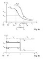
- FIG. 4a shows in a Cartesian coordinate system by way of example two not-to-scale power frequency curves P 1 (f) and P 2 (f) for the second combination of control types.
- the output powers P 1 and P 2 of the heating frequency units 10a, 12a are plotted on an ordinate axis 58. On an abscissa axis 60, the frequency f is plotted.
- the target powers P obj1 and P obj2 of the heating frequency units 10a, 12a are set by an operator.
- the first heating frequency unit 10a is operated at a frequency f 1A
- the second heating frequency unit 12a is operated at a frequency f 2A .
- the first heating frequency unit 10a is operated at a frequency f 1B and the second heating frequency unit 12a is operated at a frequency f 2B .
- the frequencies f 1A and f 2A and f 1B and f 2B each form a set of frequencies (f 1A , f 2A ), (f 1B , f 2B ), where the two frequencies of a set of frequencies (f 1A , f 2A ), (f 1B , f 2B ) differ by 18 kHz.
- the control mode used here (f 1X , f 2X ) is identical in both time intervals:
- the two heating frequency units 10a, 12a are operated in the time interval T X with a frequency difference k of 18 kHz (4). Even if the same type of control is used in both time intervals T A , T B, the frequencies used are f 1A , f 2A , f 1B , f 2B .
- FIG. 4b shows in a Cartesian coordinate system by way of example two not-to-scale power-time curves P 1 (t) and P 2 (t) for the second combination of control types FIG. 4a .
- the output powers P 1 and P 2 of the heating frequency units 10 a, 12 a are plotted on an ordinate axis 62.
- On an abscissa axis 64 the time t is plotted.
- An in FIG. 4b illustrated course of the power-time curves P 1 (t) and P 2 (t) is in a heating operation state of the heating-frequency units 10 a, 12 a periodically through the period T.
- the first heating frequency unit 10a is operated in the first time interval T A with a larger output power P 1 than in the second time interval T B.
- the second heating frequency unit 12a is operated in the first time interval T A with a smaller output power P 2 than in the second time interval T B.
- the total output power P 1 + P 2 is temporally constant and identical to the sum of the desired power P obj1 + P obj2 .
- the control unit 14a selects the second combination of control modes (f 1X , f 2X ) for the joint operation of the two heating-frequency units 10a, 12a.
- FIG. 5 a further embodiment of the invention is shown.
- the following descriptions are essentially limited to the differences between the embodiments, with respect to the same components, features and functions on the description of the other embodiment, in particular the FIGS. 1, 2 . 3a-d and 4a-b , can be referenced.
- the letter a in the reference numerals of the embodiment in the FIGS. 1, 2 . 3a-d and 4a-b by the letter b in the reference numerals of the embodiment of FIG. 5 replaced.
- identically designated components in particular with regard to components with the same reference numerals, can in principle also to the drawings and / or the description of the embodiment of FIGS. 1, 2 . 3a-d and 4a-b to get expelled.
- the control unit 14b selects for each time interval T X a control mode (f 1X , f 2X , ..., f NX ) from a catalog of control modes (f 1X , f 2X , ..., f NX ).
- the types of control (f 1X , f 2X , ..., f NX ) marked with (2) are actually N types of control (f 1X , f 2X , ..., f NX ), since the number of disconnected Schufrequenzillon 10b, 12b, a distinguishing feature of two different types of control (f 1X, 2X f, ..., f NX) represents.
- control (f 1X , f 2X , ..., f NX ) marked with (3) are also several types of control (f 1X , f 2X , ..., f NX ).
- control modes f 1X , f 2X , ..
- new types of control f 1X , f 2X , ..., f NX
- t x denotes an arbitrary time within the time interval T X
- P n denotes the output power of the n-th heating frequency unit 10b, 12b
- P objn denotes the target power of the n-th heat frequency unit 10b, 12b.
- a selection of the control modes (f 1X , f 2X , ..., f NX ) for the N time intervals T x is analogous to the selection in the previous embodiment.
- a memory unit may be provided in which characteristic power frequency curves P n (f, d j ) are stored for various typical combinations of cooking utensils and induction heating elements. Storage then preferably takes place by a manufacturer before delivery of a corresponding induction hob. This makes it possible to dispense with measuring the power-frequency curves P n (f, d j ) before starting a heating operation.
Abstract
Description
Die Erfindung geht aus von einer Gargerätevorrichtung nach dem Oberbegriff des Anspruchs 1.The invention is based on a cooking device device according to the preamble of
Die Druckschrift
Die Aufgabe der Erfindung besteht insbesondere darin, eine gattungsgemäße Gargerätevorrichtung bereitzustellen, die eine vorteilhaft flexible Einstellung einer mittleren Ausgangsleistung und eine einfache Skalierbarkeit auf eine Vielzahl von Heizfrequenzeinheiten ermöglicht. Die Aufgabe wird erfindungsgemäß durch die Merkmale des Patentanspruchs 1 und des Verfahrensanspruchs 9 gelöst, während vorteilhafte Ausgestaltungen und Weiterbildungen der Erfindung den Unteransprüchen entnommen werden können.The object of the invention is, in particular, to provide a cooking appliance device of the generic type which enables an advantageously flexible setting of an average output power and simple scalability to a multiplicity of heating frequency units. The object is achieved by the features of
Die Erfindung geht aus von einer Gargerätevorrichtung mit wenigstens einer ersten und wenigstens einer zweiten Heizfrequenzeinheit und mit wenigstens einer Steuereinheit, die dazu vorgesehen ist, die zumindest zwei Heizfrequenzeinheiten gemeinsam periodisch mit einer Periodendauer zu betreiben und die Periodendauer in zumindest zwei Zeitintervalle zu unterteilen.The invention is based on a cooking device device with at least one first and at least one second heating frequency unit and with at least one control unit which is provided to operate the at least two heating frequency units together periodically with a period duration and to divide the period into at least two time intervals.
Es wird vorgeschlagen, dass die Steuereinheit dazu vorgesehen ist, für jedes der zumindest zwei Zeitintervalle eine Steuerungsart aus einem Katalog von Steuerungsarten auszuwählen. Vorzugsweise ist die Gargerätevorrichtung als Kochfeldvorrichtung und besonders vorteilhaft als Induktionskochfeldvorrichtung ausgebildet. Unter "vorgesehen" soll insbesondere speziell programmiert und/oder ausgelegt und/oder ausgestattet verstanden werden. Darunter, dass die Steuereinheit dazu vorgesehen ist, "die Periodendauer in zumindest zwei Zeitintervalle zu unterteilen", soll insbesondere verstanden werden, dass die Steuereinheit in zumindest einem Betriebszustand innerhalb der Periodendauer zumindest zwei überlappungsfreie Zeitintervalle definiert. Vorzugsweise ist eine Summe der Längen der zumindest zwei Zeitintervalle gleich der Periodendauer. Unter einer "Heizfrequenzeinheit" soll insbesondere eine elektrische Einheit verstanden werden, die einen oszillierenden elektrischen Strom, vorzugsweise mit einer Frequenz von zumindest 15 kHz, insbesondere von wenigstens 17 kHz und vorteilhaft von mindestens 20 kHz, zu einem Betrieb wenigstens einer Heizeinheit erzeugt. Unter einer "Heizeinheit" soll insbesondere eine Einheit verstanden werden, die dazu vorgesehen ist, elektrische Energie zumindest zu einem Großteil in Wärme umzuwandeln und damit insbesondere ein Gargut zu erhitzen. Insbesondere umfasst die Heizeinheit einen Strahlungsheizkörper, einen Widerstandsheizkörper und/oder vorzugsweise einen Induktionsheizkörper, der dazu vorgesehen ist, elektrische Energie indirekt über induzierte Wirbelströme in Wärme umzuwandeln. Die Heizfrequenzeinheit umfasst insbesondere zumindest einen Wechselrichter, der vorzugsweise zwei Schalteinheiten umfasst. Unter einer "Schalteinheit" soll insbesondere eine Einheit verstanden werden, die dazu vorgesehen ist, einen zumindest einen Teil der Schalteinheit umfassenden Leitungspfad zu unterbrechen. Vorzugsweise ist die Schalteinheit ein bidirektionaler unipolarer Schalter, der insbesondere einen Stromfluss durch den Schalter entlang dem Leitungspfad in beide Richtungen ermöglicht und der insbesondere eine elektrische Spannung in zumindest einer Polungsrichtung kurzschließt. Vorzugsweise umfasst der Wechselrichter zumindest zwei Bipolartransistoren mit isolierter Gate-Elektrode und besonders vorteilhaft zumindest einen Dämpfungskondensator. Unter einem "Leitungspfad" soll insbesondere ein elektrisch leitendes Leiterstück zwischen zwei Punkten verstanden werden. Unter "elektrisch leitend" soll insbesondere mit einem spezifischen elektrischen Widerstand von höchstens 10-4 Ωm, insbesondere von maximal 10-5 Ωm, vorteilhaft von höchstens 10-6 Ωm und besonders vorteilhaft von maximal 10-7 Ωm bei 20°C verstanden werden.It is proposed that the control unit is provided for selecting a control type from a catalog of control types for each of the at least two time intervals. The cooking device device is preferably designed as a hob device and particularly advantageously as an induction hob device. By "provided" is intended to be understood in particular specially programmed and / or designed and / or equipped. By the fact that the control unit is intended to "subdivide the period into at least two time intervals", should be understood in particular that the control unit defines at least two overlap-free time intervals in at least one operating state within the period. Preferably, a sum of the lengths of the at least two time intervals is equal to the period duration. A "heating frequency unit" should in particular be understood to mean an electrical unit which generates an oscillating electrical current, preferably with a frequency of at least 15 kHz, in particular of at least 17 kHz and advantageously of at least 20 kHz, for operation of at least one heating unit. A "heating unit" is to be understood in particular as meaning a unit which is intended to convert electrical energy into heat, at least to a large extent, and thus in particular to heat a food to be cooked. In particular, the heating unit comprises a radiant heater, a resistance heater and / or preferably an induction heater, which is intended to convert electrical energy indirectly via induced eddy currents into heat. The heating frequency unit comprises in particular at least one inverter, which preferably comprises two switching units. A "switching unit" is to be understood in particular as meaning a unit which is intended to interrupt a conduction path comprising at least part of the switching unit. Preferably, the switching unit is a bidirectional unipolar switch which in particular allows a current flow through the switch along the conduction path in both directions and in particular short-circuits an electrical voltage in at least one polarity direction. Preferably, the inverter comprises at least two bipolar transistors with insulated gate electrode and particularly advantageously at least one damping capacitor. Under a "conduction path" in particular an electrically conductive Headpiece between two points to be understood. The term "electrically conductive" is to be understood in particular with a specific electrical resistance of at most 10 -4 Ωm, in particular of at most 10 -5 Ωm, advantageously of at most 10 -6 Ωm and particularly advantageously of not more than 10 -7 Ωm at 20 ° C.
Unter einer "Steuereinheit" soll insbesondere eine elektronische Einheit verstanden werden, die vorzugsweise in einer Steuer- und/oder Regeleinheit eines Gargeräts, insbesondere eines Induktionskochfelds, zumindest teilweise integriert ist und die vorzugsweise eine Recheneinheit und insbesondere zusätzlich zur Recheneinheit eine Speichereinheit mit einem darin gespeicherten Steuerprogramm umfasst. Vorzugsweise ist die Steuereinheit zumindest dazu vorgesehen, die Heizfrequenzeinheiten mit Hilfe von Steuersignalen und vorzugsweise elektrischen Steuersignalen zu steuern und/oder zu regeln. Unter einem "Steuersignal" soll insbesondere ein Signal verstanden werden, welches insbesondere in zumindest einem Betriebszustand einen Schaltvorgang einer Heizfrequenzeinheit auslöst, insbesondere auch mittelbar. Unter einem "elektrischen Steuersignal" soll insbesondere ein Steuersignal mit einem elektrischen Potential von höchstens 30 V, vorzugsweise von maximal 20 V, besonders vorteilhaft von höchstens 10 V und insbesondere von zumindest 5 V bezogen auf ein Referenzpotential verstanden werden. Vorzugsweise weist das Steuersignal zumindest zeitweise eine Periodizität auf, insbesondere mit einer Periodendauer von höchstens 1 ms, insbesondere von maximal 0,1 ms und vorteilhaft von höchstens 0,05 ms. Besonders vorteilhaft ist das Steuersignal zumindest im Wesentlichen ein Rechtecksignal, welches insbesondere zwei diskrete Werte aufweist, vorzugsweise einen Einschaltwert und einen Ausschaltwert. Vorzugsweise entspricht jeder der zwei Werte einer Schaltstellung der Heizfrequenzeinheiten und insbesondere deren Wechselrichter. Unter einer "Frequenz" einer Heizfrequenzeinheit soll insbesondere die Frequenz des die Heizfrequenzeinheit steuernden Steuersignals verstanden werden.A "control unit" is to be understood in particular as meaning an electronic unit which is preferably at least partially integrated in a control and / or regulating unit of a cooking appliance, in particular an induction hob, and which preferably has an arithmetic unit and in particular in addition to the arithmetic unit a storage unit with a stored therein Control program includes. Preferably, the control unit is at least provided to control and / or regulate the heating frequency units by means of control signals and preferably electrical control signals. A "control signal" should be understood in particular to mean a signal which, in particular in at least one operating state, triggers a switching operation of a heating frequency unit, in particular also indirectly. An "electrical control signal" is to be understood in particular to mean a control signal having an electrical potential of at most 30 V, preferably of at most 20 V, particularly advantageously of at most 10 V and in particular of at least 5 V relative to a reference potential. Preferably, the control signal has a periodicity at least at times, in particular with a period of at most 1 ms, in particular of at most 0.1 ms and advantageously of at most 0.05 ms. Particularly advantageously, the control signal is at least substantially a rectangular signal, which in particular has two discrete values, preferably a switch-on value and a switch-off value. Preferably, each of the two values corresponds to a switching position of the heating frequency units and in particular their inverter. A "frequency" of a heating frequency unit is to be understood in particular as the frequency of the control signal controlling the heating frequency unit.
Darunter, dass die Steuereinheit dazu vorgesehen ist, für jedes der zumindest zwei Zeitintervalle "eine Steuerungsart aus einem Katalog von Steuerungsarten auszuwählen", soll insbesondere verstanden werden, dass die Steuereinheit dazu vorgesehen ist, aktiv und abhängig von gegebenen Rahmenbedingungen für die zumindest zwei Zeitintervalle eine Kombination von Steuerungsarten auszuwählen. Bei den Rahmenbedingungen kann es sich um beliebige, einem Fachmann als sinnvoll erscheinende Rahmenbedingungen handeln, vorzugsweise jedoch um gewählte Sollleistungen für die wenigstens zwei Heizfrequenzeinheiten, um Verläufe der Leistungs-Frequenz-Kurven für ein gegebenes System aus Gargeschirr und Heizeinheit, um eine Vorgabe zur Minimierung von Flicker und/oder um eine Vorgabe zur Minimierung einer Schwankung von Ausgangsleistungen der Heizfrequenzeinheiten handeln. Unter "Flicker" soll insbesondere ein subjektiver Eindruck einer Instabilität einer visuellen Wahrnehmung verstanden werden, der insbesondere durch einen Lichtreiz hervorgerufen wird, dessen Leuchtdichte und/oder Spektralverteilung mit der Zeit schwankt. Insbesondere kann Flicker durch einen Spannungsabfall einer Netzspannung hervorgerufen werden.By the fact that the control unit is intended to select "one type of control from a catalog of control types" for each of the at least two time intervals, it should be understood in particular that the control unit is intended to be active and dependent on given conditions for the at least two time intervals Select combination of control types. The boundary conditions may be any boundary conditions that appear appropriate to a person skilled in the art, but preferably selected output powers for the at least two heating frequency units, curves of the power frequency curves for a given system of cooking utensils and heating unit, a specification for minimization by Flicker and / or by a requirement to minimize fluctuation in the output of heating units. By "flicker" is meant in particular a subjective impression of an instability of a visual perception, which is caused in particular by a light stimulus whose luminance and / or spectral distribution varies with time. In particular, flicker can be caused by a voltage drop of a mains voltage.
Unter einer "Steuerungsart" soll insbesondere eine Art der Steuerung der wenigstens zwei Heizfrequenzeinheiten durch die Steuereinheit in einem Zeitintervall verstanden werden, wobei zwei unterschiedliche Steuerungsarten insbesondere dadurch abgegrenzt sind, dass die beiden Steuerungsarten eine unterschiedliche Anzahl betriebener Heizfrequenzeinheiten und/oder eine unterschiedliche Anzahl von verwendeten Frequenzen aufweisen und/oder sich durch zumindest eine Berechnungsart und vorzugsweise eine frequenzunabhängige Berechnungsart unterscheiden, mittels deren wenigstens eine verwendete Frequenz der Steuerungsart aus einer anderen verwendeten Frequenz der Steuerungsart hervorgeht. Unter einer "verwendeten Frequenz" einer Steuerungsart soll insbesondere ein Zahlenwert einer in der Steuerungsart verwendeten Frequenz verstanden werden, wobei Null ebenfalls als ein Zahlenwert anzusehen ist. Unter einer "Berechnungsart" soll insbesondere eine Art einer Berechnung mittels zumindest eines mathematischen Operators verstanden werden, wobei die Berechnungsart ausschließlich durch den zumindest einen mathematischen Operator und insbesondere dessen Anordnung zu weiteren mathematischen Operatoren definiert ist. Insbesondere sollen bei der Unterscheidung zweier Berechnungsarten Zahlenwerte von Konstanten irrelevant sein. Vorzugsweise handelt es sich bei der Berechnungsart um eine "einfache Berechnungsart", die insbesondere genau einen mathematischen Operator, wie insbesondere einen Additionsoperator, aufweist. Vorzugsweise besteht die Berechnungsart in einer Addition einer frequenzunabhängigen Konstante, wobei ein genauer Zahlenwert der Konstante irrelevant ist. Darunter, dass eine Heizfrequenzeinheit "betrieben" wird, soll insbesondere verstanden werden, dass die Frequenz der Heizfrequenzeinheit im betreffenden Zeitintervall von Null verschieden ist. Vorzugsweise erlaubt jede Steuerungsart einen gemeinsamen Betrieb der wenigstens zwei Heizfrequenzeinheiten unter zumindest weitgehender Vermeidung von Intermodulationsgeräuschen. Unter "Intermodulationsgeräuschen" sollen insbesondere Geräusche verstanden werden, deren Frequenzspektren zumindest einen von Null verschiedenen Anteil mit einer Frequenz von weniger als 18 kHz, insbesondere von weniger als 17 kHz, vorzugsweise von weniger als 16 kHz und besonders vorteilhaft von weniger als 15 kHz aufweisen. Darunter, dass eine Steuerungsart einen gemeinsamen Betrieb der wenigstens zwei Heizfrequenzeinheiten "unter zumindest weitgehender Vermeidung von Intermodulationsgeräuschen" erlaubt, soll insbesondere verstanden werden, dass bei einem gemeinsamen Betrieb der wenigstens zwei Heizfrequenzeinheiten gemäß der Steuerungsart Intermodulationsgeräusche in einem Abstand von 1 m von der Gargerätevorrichtung einen Schalldruckpegel von höchstens 20 dB, insbesondere von maximal 10 dB, vorzugsweise von höchstens 5 dB und besonders vorteilhaft von maximal 0 dB aufweisen. Vorzugsweise sind die Intermodulationsgeräusche dann von einem Bediener mit durchschnittlichem Gehör unhörbar.A "type of control" is to be understood in particular as a type of control of the at least two heating frequency units by the control unit in a time interval, two different types of control being delineated, in particular, by the two types of control using a different number of operated heating frequency units and / or a different number of used Have frequencies and / or differ by at least one type of calculation and preferably a frequency-independent calculation, by means of which at least one frequency used the type of control results from another frequency used the type of control. A "used frequency" of a type of control should be understood to mean, in particular, a numerical value of a frequency used in the type of control, whereby zero should also be regarded as a numerical value. A "type of calculation" is understood to mean, in particular, a type of calculation by means of at least one mathematical operator, the type of calculation is defined exclusively by the at least one mathematical operator and in particular its arrangement to further mathematical operators. In particular, numerical values of constants should be irrelevant when differentiating between two types of calculation. The type of calculation is preferably a "simple calculation type", which in particular has exactly one mathematical operator, in particular an addition operator. Preferably, the calculation type is an addition of a frequency-independent constant, an exact numerical value of the constant being irrelevant. By the fact that a heating frequency unit is "operated" should be understood in particular that the frequency of the heating frequency unit in the relevant time interval is different from zero. Preferably, each type of control allows a common operation of the at least two heating frequency units, at least largely avoiding intermodulation noise. By "intermodulation noise" is meant, in particular, sounds whose frequency spectra have at least one non-zero component with a frequency of less than 18 kHz, in particular less than 17 kHz, preferably less than 16 kHz and particularly advantageously less than 15 kHz. The fact that a type of control permits a common operation of the at least two heating frequency units "with at least largely avoiding intermodulation noises" is to be understood in particular as meaning that in a joint operation of the at least two heating frequency units according to the type of control intermodulation noises at a distance of 1 m from the cooking appliance apparatus Have a maximum sound pressure level of 20 dB, in particular of at most 10 dB, preferably of at most 5 dB and particularly advantageously of at most 0 dB. Preferably, the intermodulation sounds are then inaudible by an average hearing operator.
Unter einem "Katalog von Steuerungsarten" soll insbesondere eine Sammlung verschiedener Steuerungsarten verstanden werden. Als Steuerungsarten kommen alle, einem Fachmann als sinnvoll erscheinenden Steuerungsarten in Frage. Vorzugsweise gehört zum Katalog der Steuerungsarten eine Steuerungsart, bei der alle Heizfrequenzeinheiten mit der gleichen, von Null verschiedenen Frequenz betrieben werden. Vorzugsweise gehört zum Katalog der Steuerungsarten eine Steuerungsart, bei der alle Heizfrequenzeinheiten abgeschaltet werden. Vorzugsweise gehören zum Katalog der Steuerungsarten Steuerungsarten, bei denen zumindest eine Heizfrequenzeinheit abgeschaltet wird und die übrigen Heizfrequenzeinheiten mit der gleichen Frequenz betrieben werden. Vorzugsweise gehören zum Katalog der Steuerungsarten Steuerungsarten, bei denen alle Heizfrequenzeinheiten betrieben werden und eine Differenz zwischen Frequenzen zweier beliebiger Heizfrequenzeinheiten Null oder zumindest 15 kHz, insbesondere wenigstens 16 kHz, vorzugsweise mindestens 17 kHz und besonders vorteilhaft zumindest 18 kHz beträgt. Vorzugsweise gehören zum Katalog der Steuerungsarten Steuerungsarten, bei denen zumindest eine Heizfrequenzeinheit abgeschaltet wird und eine Differenz zwischen Frequenzen zweier beliebiger betriebener Heizfrequenzeinheiten Null oder zumindest 15 kHz, insbesondere wenigstens 16 kHz, vorzugsweise mindestens 17 kHz und besonders vorteilhaft zumindest 18 kHz beträgt. Darunter, dass eine Heizfrequenzeinheit in einem Zeitintervall "abgeschaltet" wird, soll insbesondere verstanden werden, dass die Heizfrequenzeinheit im betreffenden Zeitintervall zumindest im Wesentlichen eine verschwindend geringe Ausgangsleistung aufweist. Unter einer "im betreffenden Zeitintervall zumindest im Wesentlichen verschwindend geringen Ausgangsleistung" soll insbesondere eine Ausgangsleistung verstanden werden, die höchstens 50 W, insbesondere maximal 25 W, vorzugsweise höchstens 10 W und besonders vorteilhaft 0 W beträgt und/oder die im Zeitintervall ausschließlich während einer Zeitdauer abgegeben wird, welche höchstens 50%, insbesondere maximal 25%, vorzugsweise höchstens 15% und besonders vorteilhaft höchstens 10% einer Länge des Zeitintervalls entspricht. Unter einer "Ausgangsleistung" einer der wenigstens zwei Heizfrequenzeinheiten soll insbesondere eine Leistung verstanden werden, die in wenigstens einem Heizbetriebszustand von der Heizfrequenzeinheit geliefert wird.A "catalog of control types" is to be understood in particular as a collection of different types of control. As control modes are all, one of the expert appear appropriate sense control types in question. Preferably belongs to the catalog of control types a type of control all heating frequency units are operated at the same non-zero frequency. Preferably belongs to the catalog of control types a type of control in which all heating frequency units are turned off. Preferably belong to the catalog of control types control types in which at least one heating frequency unit is turned off and the other heating frequency units are operated at the same frequency. Preferably, the catalog of control types control types in which all heating frequency units are operated and a difference between frequencies of any two heating frequency units zero or at least 15 kHz, in particular at least 16 kHz, preferably at least 17 kHz and more preferably at least 18 kHz. Preferably, the catalog of control types control types in which at least one Heizfrequenzeinheit is turned off and a difference between frequencies of any two operated Heizfrequenzeinheiten zero or at least 15 kHz, in particular at least 16 kHz, preferably at least 17 kHz and more preferably at least 18 kHz. The fact that a heating frequency unit is "switched off" in a time interval should in particular be understood to mean that the heating frequency unit has at least substantially a negligibly low output power in the relevant time interval. A "at least substantially negligibly low output power in the relevant time interval" is to be understood in particular as an output power which is at most 50 W, in particular at most 25 W, preferably at most 10 W and particularly advantageously 0 W and / or during the time interval exclusively during a period of time is delivered, which corresponds to at most 50%, in particular at most 25%, preferably at most 15% and most preferably at most 10% of a length of the time interval. An "output power" of one of the at least two heating-frequency units should in particular be understood to mean a power which is supplied by the heating-frequency unit in at least one heating operating state.
Durch eine solche Ausgestaltung kann eine vorteilhaft flexible Einstellung einer mittleren Ausgangsleistung erreicht werden. Des Weiteren kann eine einfache Skalierbarkeit auf eine Vielzahl von Heizfrequenzeinheiten ermöglicht werden.By means of such an embodiment, an advantageously flexible setting of an average output power can be achieved. Furthermore, a simple scalability to a variety of heating frequency units can be made possible.
In einer bevorzugten Ausgestaltung der Erfindung wird vorgeschlagen, dass die Steuereinheit dazu vorgesehen ist, diejenigen Steuerungsarten für die zumindest zwei Zeitintervalle auszuwählen, die einen Betrieb der wenigstens zwei Heizfrequenzeinheiten mit möglichst geringen Schwankungen einer Gesamtausgangsleistung der wenigstens zwei Heizfrequenzeinheiten und/oder einer jeweiligen Ausgangsleistung der wenigstens zwei Heizfrequenzeinheiten ermöglichen. Unter einer "Gesamtausgangsleistung" der wenigstens zwei Heizfrequenzeinheiten soll insbesondere eine Summe der Ausgangsleistungen der wenigstens zwei Heizfrequenzeinheiten verstanden werden. Darunter, dass die Steuereinheit dazu vorgesehen ist, diejenigen Steuerungsarten auszuwählen, die einen Betrieb der wenigstens zwei Heizfrequenzeinheiten "mit möglichst geringen Schwankungen einer jeweiligen Ausgangsleistung" ermöglichen, soll insbesondere verstanden werden, dass vorgesehen ist, diejenigen Steuerungsarten auszuwählen, bei denen eine größte maximale Schwankung der Ausgangsleistung der wenigstens zwei Heizfrequenzeinheiten minimal ist. Vorzugsweise ist die Steuereinheit dazu vorgesehen, diejenigen Steuerungsarten für die wenigstens zwei Zeitintervalle zu betrachten, für die die Gesamtausgangsleistung zumindest weitgehend konstant ist und aus diesen Steuerungsarten diejenigen auszuwählen, welche einen Betrieb der wenigstens zwei Heizfrequenzeinheiten mit möglichst geringen Schwankungen einer jeweiligen Ausgangsleistung ermöglichen. Darunter, dass eine "Gesamtausgangsleistung zumindest weitgehend konstant ist", soll insbesondere verstanden werden, dass die Gesamtausgangsleistung in wenigstens einem Betriebszustand eine relative zeitliche Schwankung aufweist, die kleiner als ein durch gesetzliche Vorgaben und/oder Normen, insbesondere durch die Norm DIN EN 61000-3-3 festgelegter Flickergrenzwert ist. Hierdurch kann ein Bedienkomfort vorteilhaft gesteigert werden, da eine zumindest weitgehend gleichmäßige Leistungsabgabe erzielt und Flicker minimiert werden kann.In a preferred embodiment of the invention, it is proposed that the control unit is provided to select those types of control for the at least two time intervals, the operation of the at least two Heizfrequenzeinheiten with minimal fluctuations in total output power of the at least two Heizfrequenzeinheiten and / or a respective output of the at least enable two heating frequency units. A "total output power" of the at least two heating frequency units should in particular be understood as meaning a sum of the output powers of the at least two heating frequency units. By the fact that the control unit is intended to select those types of control which allow operation of the at least two heating frequency units "with the lowest possible fluctuations of a respective output power" should be understood in particular that it is intended to select those types of control in which a maximum maximum fluctuation the output power of the at least two Heizfrequenzeinheiten is minimal. Preferably, the control unit is provided to consider those types of control for the at least two time intervals for which the total output power is at least substantially constant and to select from these types of control those which allow operation of at least two Heizfrequenzeinheiten with the lowest possible fluctuations of a respective output power. By the fact that a "total output power is at least largely constant" should be understood in particular that the total output power in at least one operating state has a relative temporal fluctuation, which is smaller than a legal requirements and / or standards, in particular by the standard DIN EN 61000- 3-3 is the specified flicker limit. As a result, an ease of use can be increased advantageously, since an at least largely uniform power output achieved and flicker can be minimized.
In einer besonders bevorzugten Ausgestaltung der Erfindung wird vorgeschlagen, dass die Steuereinheit dazu vorgesehen ist, gemäß den ausgewählten Steuerungsarten für jedes der zumindest zwei Zeitintervalle Frequenzen von Steuersignalen der zumindest zwei Heizfrequenzeinheiten unter zumindest weitgehender zeitlicher Konstanthaltung einer Gesamtausgangsleistung der wenigstens zwei Heizfrequenzeinheiten zu bestimmen. Darunter, dass die Steuereinheit dazu vorgesehen ist, die Frequenzen der Steuersignale "unter zumindest weitgehender zeitlicher Konstanthaltung einer Gesamtausgangsleistung" zu bestimmen, soll insbesondere verstanden werden, dass die Steuereinheit in zumindest einem Betriebszustand die Frequenzen der Heizfrequenzeinheiten derart festlegt, dass die Gesamtausgangsleistung eine relative zeitliche Schwankung aufweist, die kleiner als ein durch gesetzliche Vorgaben und/oder Normen, insbesondere durch die Norm DIN EN 61000-3-3 festgelegter Flickergrenzwert ist. Hierdurch kann Flicker vorteilhaft minimiert werden.In a particularly preferred embodiment of the invention, it is proposed that the control unit be provided to determine, for at least two time intervals, frequencies of control signals of the at least two heating frequency units under at least substantially constant temporal stabilization of a total output power of the at least two heating frequency units according to the selected control modes. By the fact that the control unit is intended to determine the frequencies of the control signals "at least substantially constant temporal constant total output", should be understood in particular that the control unit determines the frequencies of the heating frequency units in at least one operating state such that the total output power a relative temporal Fluctuation which is smaller than a flicker limit specified by legal requirements and / or standards, in particular by the standard DIN EN 61000-3-3. As a result, flicker can be advantageously minimized.
Ferner wird vorgeschlagen, dass die Steuereinheit dazu vorgesehen ist, mittlere Ausgangsleistungen der wenigstens zwei Heizfrequenzeinheiten an gewählte Sollleistungen anzupassen. Unter einer "mittleren Ausgangsleistung" soll insbesondere eine zeitlich gemittelte Ausgangsleistung verstanden werden. Dabei soll eine relative Abweichung der durch die Steuereinheit eingestellten mittleren Ausgangsleistung von der Sollleistung höchstens 10%, vorzugsweise maximal 5% und besonders vorteilhaft höchstens 1% betragen. Hierdurch kann ein hoher Bedienkomfort erzielt werden. Vorzugsweise ist die mittlere Ausgangsleistung einer der wenigstens zwei Heizfrequenzeinheiten stets kleiner als oder gleich wie die Sollleistung der entsprechenden Heizfrequenzeinheit. Hierdurch können unsichere Betriebszustände vermieden werden.It is also proposed that the control unit is provided to adapt average output powers of the at least two heating frequency units to selected desired powers. A "mean output power" is to be understood in particular a time-averaged output power. In this case, a relative deviation of the set by the control unit average output power of the target power should be at most 10%, preferably at most 5% and more preferably at most 1%. As a result, a high level of operating comfort can be achieved. Preferably, the average output power of one of the at least two heating frequency units is always less than or equal to the desired power of the corresponding heating frequency unit. As a result, unsafe operating conditions can be avoided.
Vorteilhaft ist die Steuereinheit dazu vorgesehen, eine Anpassung der mittleren Ausgangsleistungen der wenigstens zwei Heizfrequenzeinheiten durch eine Anpassung der zumindest zwei Zeitintervalle vorzunehmen, insbesondere unter Konstanthaltung der zuvor bestimmten Frequenzen. Hierdurch kann ein vorteilhaft hoher Bedienkomfort erreicht werden, da einerseits Flicker minimiert und andererseits eine der Sollleistung angepasste mittlere Ausgangsleistung bereitgestellt werden kann.Advantageously, the control unit is provided to make an adjustment of the average output power of the at least two heating frequency units by adjusting the at least two time intervals, in particular while keeping constant the previously determined frequencies. As a result, an advantageously high ease of use can be achieved, since on the one hand minimizes flicker and on the other hand, a desired power adjusted average output power can be provided.
In einer weiteren Ausgestaltung der Erfindung wird vorgeschlagen, dass die Steuereinheit dazu vorgesehen ist, die zumindest zwei Heizfrequenzeinheiten jeweils mittels eines Steuersignals zu steuern und/oder zu regeln und in wenigstens einem Betriebszustand einen Tastgrad von zumindest einem der Steuersignale anzupassen. Unter einem "Tastgrad" soll insbesondere ein Verhältnis einer Zeitdauer, in der das Steuersignal innerhalb einer Periodendauer den Einschaltwert annimmt, zur Periodendauer des Steuersignals verstanden werden. Vorzugsweise kann bei fester Frequenz einer der Heizfrequenzeinheiten durch eine Veränderung des Tastgrads eine Ausgangsleistung der Heizfrequenzeinheit verändert werden. Darunter, dass die Steuereinheit dazu vorgesehen ist, "einen Tastgrad von zumindest einem der Steuersignale anzupassen", soll insbesondere verstanden werden, dass die Steuereinheit dazu vorgesehen ist, den Tastgrad von zumindest einem der Steuersignale zu verändern, um hierdurch eine Änderung einer Ausgangsleistung bei fester Frequenz einer Heizfrequenzeinheit zu erreichen. Hierdurch kann eine Flexibilität bei einer Einstellung der mittleren Ausgangsleistungen der wenigstens zwei Heizfrequenzeinheiten weiter vorteilhaft erhöht werden.In a further embodiment of the invention, it is proposed that the control unit is provided to control and / or regulate the at least two heating frequency units in each case by means of a control signal and to adjust a duty cycle of at least one of the control signals in at least one operating state. In particular, a ratio of a time duration in which the control signal assumes the switch-on value within a period duration to the period duration of the control signal is to be understood as a "duty cycle". Preferably, at a fixed frequency of one of the heating frequency units by changing the duty cycle, an output of the heating frequency unit can be changed. By the fact that the control unit is intended to "adjust a duty cycle of at least one of the control signals", it should be understood in particular that the control unit is intended to change the duty cycle of at least one of the control signals, thereby changing a fixed output power Frequency of a heating frequency unit. In this way, flexibility in setting the mean output powers of the at least two heating frequency units can be further advantageously increased.
Ferner wird vorgeschlagen, dass die Steuereinheit dazu vorgesehen ist, die Periodendauer in eine Anzahl von Zeitintervallen zu unterteilen, die einer Anzahl gleichzeitig zu betreibender Heizfrequenzeinheiten entspricht. Vorzugsweise folgen die Zeitintervalle unmittelbar aufeinander, so dass eine Summe von Längen der Zeitintervalle der Periodendauer entspricht. Hierdurch kann das erfindungsgemäße Steuerungsverfahren für eine Gargerätevorrichtung mit mehr als zwei Heizfrequenzeinheiten und insbesondere auf eine Gargerätevorrichtung für ein Matrix-Kochfeld skaliert werden. Unter einem "Matrix-Kochfeld" soll insbesondere ein Kochfeld verstanden werden, bei dem Heizeinheiten in einem regelmäßigen Raster unter einer Kochfeldplatte angeordnet sind, und ein mittels der Heizeinheiten heizbarer Bereich der Kochfeldplatte vorzugsweise wenigstens 60%, insbesondere zumindest 70%, vorteilhaft zumindest 80% und besonders vorteilhaft wenigstens 90% einer Gesamtfläche der Kochfeldplatte umfasst. Insbesondere umfasst das Matrix-Kochfeld zumindest 10, insbesondere mindestens 20, vorteilhaft wenigstens 30 und besonders vorteilhaft zumindest 40 Heizeinheiten.Furthermore, it is proposed that the control unit be provided to subdivide the period into a number of time intervals corresponding to a number of heating frequency units to be operated simultaneously. The time intervals preferably follow one another directly so that a sum of lengths corresponds to the time intervals of the period. As a result, the control method according to the invention for a cooking device device with more than two heating frequency units and in particular to a cooking appliance device for a matrix hob can be scaled. A "matrix hob" is to be understood in particular a hob, are arranged in the heating units in a regular grid under a hob plate, and a heatable by means of the heating units of the hob plate preferably at least 60%, in particular at least 70%, advantageously at least 80% and particularly advantageously comprises at least 90% of a total area of the hob plate. In particular, the matrix cooktop comprises at least 10, in particular at least 20, advantageously at least 30 and particularly advantageously at least 40 heating units.
Vorteilhaft ist die Steuereinheit dazu vorgesehen, Leistungs-Frequenz-Kurven für verschiedene Tastgrade eines Steuersignals der wenigstens zwei Heizfrequenzeinheiten zu bestimmen. Unter einer "Leistungs-Frequenz-Kurve" soll insbesondere ein für jede Kombination aus einem Gargeschirr und einer Heizeinheit spezifischer und vom Tastgrad abhängiger funktioneller Zusammenhang verstanden werden, der bei gegebenem Tastgrad jeder Frequenz eindeutig eine Ausgangsleistung zuordnet. Darunter, dass die Steuereinheit dazu vorgesehen ist, "Leistungs-Frequenz-Kurven für verschiedene Tastgrade eines Steuersignals der wenigstens zwei Heizfrequenzeinheiten zu bestimmen", soll insbesondere verstanden werden, dass die Steuereinheit in zumindest einem Betriebszustand eine der wenigstens zwei Heizfrequenzeinheiten mit unterschiedlichen Frequenzen kurzzeitig betreibt und für jede dieser Frequenzen die Ausgangsleistung der wenigstens einen Heizfrequenzeinheit aus einer Messeinheit ausliest. Hierdurch kann ein vorteilhaft präziser Heizbetrieb ermöglicht werden.Advantageously, the control unit is provided to determine power frequency curves for different duty cycles of a control signal of the at least two heating frequency units. A "power frequency curve" is to be understood, in particular, as a functional relationship that is specific for each combination of a cooking utensil and a heating unit and dependent on the duty factor, which unambiguously assigns an output power to each frequency for a given duty cycle. By the fact that the control unit is intended to "determine power frequency curves for different duty cycles of a control signal of the at least two heating frequency units" should be understood in particular that the control unit operates in at least one operating state of the at least two Heizfrequenzeinheiten with different frequencies for a short time and for each of these frequencies the output power of the at least one heating frequency unit is read from a measuring unit. In this way, an advantageously precise heating operation can be made possible.
Ferner wird ein Verfahren mit einer Gargerätevorrichtung mit wenigstens einer ersten und wenigstens einer zweiten Heizfrequenzeinheit, insbesondere nach einem der vorhergehenden Ansprüche, vorgeschlagen, bei dem die Heizfrequenzeinheiten gemeinsam periodisch mit einer Periodendauer betrieben werden und die Periodendauer in zumindest zwei Zeitintervalle unterteilt wird, wobei für jedes der zumindest zwei Zeitintervalle zur Minimierung von Intermodulationsgeräuschen eine Steuerungsart aus einem Katalog von Steuerungsarten ausgewählt wird. Hierdurch kann eine vorteilhaft flexible Einstellung einer mittleren Ausgangsleistung und eine einfache Skalierbarkeit auf eine Vielzahl von Heizfrequenzeinheiten ermöglicht werden.Furthermore, a method is proposed with a cooking device device having at least one first and at least one second heating frequency unit, in particular according to one of the preceding claims, in which the heating frequency units are operated together periodically with a period duration and the period duration is subdivided into at least two time intervals, wherein for each the at least two time intervals for minimizing intermodulation noises one control type is selected from a catalog of control types. As a result, an advantageously flexible setting of an average output power and a simple scalability to a plurality of heating frequency units can be made possible.
Ferner wird ein Gargerät, insbesondere ein Kochfeld, mit einer erfindungsgemäßen Gargerätevorrichtung vorgeschlagen. Vorzugsweise handelt es sich bei dem Kochfeld um ein Induktionskochfeld. Das Kochfeld kann ferner ein Matrix-Kochfeld und besonders vorteilhaft ein Matrix-Induktionskochfeld sein. Unter einem "Matrix-Induktionskochfeld" soll insbesondere ein Matrix-Kochfeld verstanden werden, das zumindest eine einen Induktionsheizkörper umfassende Heizeinheit aufweist.Furthermore, a cooking appliance, in particular a hob, proposed with a Gargerätevorrichtung invention. Preferably, the hob is an induction hob. The cooktop can also be a matrix cooktop, and more preferably a matrix induction cooktop. A "matrix induction hob" is to be understood, in particular, as a matrix hob which has at least one heating unit comprising an induction heater.
Weitere Vorteile ergeben sich aus der folgenden Zeichnungsbeschreibung. In der Zeichnung sind zwei Ausführungsbeispiele der Erfindung dargestellt. Die Zeichnung, die Beschreibung und die Ansprüche enthalten zahlreiche Merkmale in Kombination. Der Fachmann wird die Merkmale zweckmäßigerweise auch einzeln betrachten und zu sinnvollen weiteren Kombinationen zusammenfassen.Further advantages emerge from the following description of the drawing. In the drawing, two embodiments of the invention are shown. The drawing, the description and the claims contain numerous features in combination. The person skilled in the art will expediently also consider the features individually and combine them into meaningful further combinations.
Es zeigen:
- Fig. 1
- ein Induktionskochfeld mit einer erfindungsgemäßen Gargerätevorrichtung mit zwei Heizfrequenzeinheiten,
- Fig. 2
- ein beispielhaftes, nicht maßstabsgetreues Steuersignal einer der zwei Heizfrequenzeinheiten,
- Fig. 3a
- beispielhafte, nicht maßstabsgetreue Leistungs-Frequenz-Kurven für die zwei Heizfrequenzeinheiten gemäß einer ersten Kombination aus Steuerungsarten,
- Fig. 3b
- je eine beispielhafte, nicht maßstabsgetreue Leistungs-Zeit-Kurve für die zwei Heizfrequenzeinheiten gemäß der ersten Kombination der Steuerungsarten aus
Fig. 3a , - Fig. 3c
- beispielhafte, nicht maßstabsgetreue Leistungs-Frequenz-Kurven einer der zwei Heizfrequenzeinheiten bei unterschiedlichen Tastgraden eines Steuersignals,
- Fig. 3d
- beispielhafte, nicht maßstabsgetreue Gesamtleistungs-Zeit-Kurven gemäß der ersten Kombination der Steuerungsarten aus
Fig. 3a , - Fig.4a
- beispielhafte, nicht maßstabsgetreue Leistungs-Frequenz-Kurven für die zwei Heizfrequenzeinheiten gemäß einer zweiten Kombination aus Steuerungsarten,
- Fig. 4b
- je eine beispielhafte, nicht maßstabsgetreue Leistungs-Zeit-Kurve für die zwei Heizfrequenzeinheiten gemäß der zweiten Kombination der Steuerungsarten aus
Fig. 4a und - Fig. 5
- beispielhafte, nicht maßstabsgetreue Leistungs-Zeit-Kurven für N gleichzeitig betriebene Heizfrequenzeinheiten einer weiteren erfindungsgemäßen Gargerätevorrichtung.
- Fig. 1
- an induction hob with a cooking appliance device according to the invention with two heating frequency units,
- Fig. 2
- an exemplary, not to scale, control signal of one of the two heating frequency units,
- Fig. 3a
- exemplary, not to scale true power frequency curves for the two heating frequency units according to a first combination of control types,
- Fig. 3b
- an exemplary, not to scale true power-time curve for the two heating frequency units according to the first combination of control types
Fig. 3a . - Fig. 3c
- exemplary, not to scale power frequency curves of one of the two heating frequency units at different duty cycles of a control signal,
- Fig. 3d
- exemplary, non-to-scale total power-time curves according to the first combination of control types
Fig. 3a . - 4a
- exemplary, not to scale true power frequency curves for the two heating frequency units according to a second combination of control types,
- Fig. 4b
- an exemplary, not to scale true power-time curve for the two Heizfrequenzeinheiten according to the second combination of control types
Fig. 4a and - Fig. 5
- exemplary, not to scale power-time curves for N simultaneously operated Heizfrequenzeinheiten another cooking appliance device according to the invention.

Hierbei bezeichnen P1(t) die Ausgangsleistung der ersten Heizfrequenzeinheit 10a zur Zeit t und P2(t) die Ausgangsleistung der zweiten Heizfrequenzeinheit 12a zur Zeit t. Die Steuereinheit 14a steuert die erste Heizfrequenzeinheit 10a mittels eines Steuersignals V1(t) und die zweite Heizfrequenzeinheit 12a mittels eines Steuersignals V2(t).Here, P 1 (t) designates the output power of the first
Für einen gemeinsamen Betrieb der zwei Heizfrequenzeinheiten 10a, 12a sind bestimmte Bedingungen an die Frequenzen f1X, f2X der Steuersignale V1(t), V2(t) der Heizfrequenzeinheiten 10a, 12a zu stellen, um von einem Bediener als störend empfundene Intermodulationsgeräusche zu minimieren. Der Index "X" steht hierbei stellvertretend für die Buchstaben "A" und "B", welche die Zeitintervalle TA und TB kennzeichnen. Im Fall von zwei gleichzeitig zu betreibenden Heizfrequenzeinheiten 10a, 12a sind folgende weitgehend intermodulationsfreie Steuerungsarten (f1X, f2X) für ein Zeitintervall TX denkbar: (1) Beide Heizfrequenzeinheiten 10a, 12a werden im Zeitintervall TX mit der gleichen von Null verschiedenen Frequenz f1X, f2X betrieben. (2) Eine der zwei Heizfrequenzeinheiten 10a, 12a wird im Zeitintervall TX abgeschaltet. (3) Beide Heizfrequenzeinheiten 10a, 12a werden im Zeitintervall TX abgeschaltet. (4) Die zwei Heizfrequenzeinheiten 10a, 12a werden im Zeitintervall TX mit einer Frequenzdifferenz k betrieben, wobei die Frequenzdifferenz k zumindest 15 kHz beträgt. Es ist Aufgabe der Steuereinheit 14a, aus diesem Katalog von Steuerungsarten (f1X, f2X) für jedes der zwei Zeitintervalle TA und TB eine passende Steuerungsart (f1X, f2X) auszuwählen und die Heizfrequenzeinheiten 10a, 12a gemäß dieser Steuerungsart (f1X, f2X) gemeinsam zu betreiben, so dass die mittlere Ausgangsleistung Pave1, Pave2 einer jeden Heizfrequenzeinheit 10a, 12a ihrer Sollleistung Pobj1, Pobj2 entspricht.For a joint operation of the two
Für den Fall, dass ein Bediener mittels der Bedien- und Anzeigeeinheit 30a einen gleichzeitigen Betrieb beider Heizfrequenzeinheiten 10a, 12a anwählt, prüft die Steuereinheit 14a zunächst, ob zur induktiven Erwärmung taugliches Gargeschirr auf den Heizzonen 20a, 22a der Kochfeldplatte 18a platziert ist. Ist dies der Fall, so bestimmt die Steuereinheit 14a in einem nächsten Schritt für verschiedene Tastgrade dj Leistungs-Frequenz-Kurven P1(f,dj), P2(f,dj) einer gegebenen Kombination aus Induktionsheizeinheit und Gargeschirr. Hierzu ändert die Steuereinheit 14a für einen festen Tastgrad dj schrittweise eine Frequenz f eines Steuersignals V1(t), V2(t) ausgehend von einer Höchstfrequenz fmax zu einer jeweiligen Mindestfrequenz fmin1, fmin2, betreibt die jeweilige Heizfrequenzeinheit 10a, 12a kurzzeitig mit der eingestellten Frequenz f und liest die Ausgangsleistung P1, P2 der betreffenden Heizfrequenzeinheit 10a, 12a aus einer Messeinheit der Gargerätevorrichtung aus. Die Steuereinheit 14a führt diese Bestimmung für Tastgrade dj = 50%, 40%, 30%, 20% und 10% durch. Beispielhaft ergeben sich hierdurch für die Heizfrequenzeinheit 10a die in
Da zwei Heizfrequenzeinheiten 10a, 12a gleichzeitig zu betreiben sind, ist die Periodendauer T in die zwei Zeitintervalle TA und TB zu unterteilen, deren Längen in einem späteren Schritt bestimmt werden. Zunächst wählt die Steuereinheit 14a aus einem Katalog von Steuerungsarten (f1X, f2X) für jedes der zwei Zeitintervalle TA, TB eine Steuerungsart (f1X, f2X) aus, so dass bei entsprechender Wahl der Frequenzen f1A, f2A, f1B, f2B und von Tastgraden D1A, D2A, D1B, D2B möglichst geringe Schwankungen der Gesamtausgangsleistung P1 + P2 der zwei Heizfrequenzeinheiten 10a, 12a und einer jeweiligen Ausgangsleistung P1, P2 der wenigstens zwei Heizfrequenzeinheiten 10, 12 auftreten. Die Steuereinheit 14a betrachtet hierzu alle Steuerungsarten (f1X, f2X), für die die Gesamtausgangsleistungsdifferenz F beim Übergang vom ersten Zeitintervall TA zum zweiten Zeitintervall TB bei entsprechender Wahl der Frequenzen f1A, f2A, f1B, f2B und von Tastgraden D1A, D2A, D1B, D2B kleiner ist als ein durch die Norm DIN EN 61000-3-3 festgelegter Flickergrenzwert G: ![]()
und ![]()
wobei tA bzw. tB einen beliebigen Zeitpunkt innerhalb des Zeitintervalls TA bzw. TB kennzeichnet. Hierbei gelten zusätzliche Grenzwerte für die Frequenzen f1A, f2A, f1B, f2B. Zum einen existiert jeweils die kurvenspezifische Mindestfrequenz fmin1 und fmin2 und damit eine maximal erreichbare Ausgangsleistung P1, P2 für jede Heizfrequenzeinheit 10a, 12a. Des Weiteren existiert die gemeinsame durch elektronische Restriktionen gegebene Höchstfrequenz fmax und damit eine in einem kontinuierlichen Betrieb minimal erreichbare Ausgangsleistung P1, P2 für jede Heizfrequenzeinheit 10a, 12a. Der gültige Frequenzbereich ist also folgendermaßen eingeschränkt: ![]()
![]()
and ![]()
where t A and t B a desired time within the time interval T A and T B indicates. In this case, additional limit values apply for the frequencies f 1A , f 2A , f 1B , f 2B . On the one hand, there exists in each case the curve-specific minimum frequency f min1 and f min2 and thus a maximum achievable output power P 1 , P 2 for each ![]()
Aus den betrachteten Steuerungsarten (f1X, f2X) wählt die Steuereinheit 14a für den gemeinsamen Betrieb der Heizfrequenzeinheiten 10a, 12a schließlich diejenige Steuerungsart (f1X, f2X) aus, für die eine maximale Schwankung der Ausgangsleistung P1, P2 einer jeden Heizfrequenzeinheit 10a, 12a minimal ist. Im Anschluss daran bestimmt die Steuereinheit 14a die Längen der Zeitintervalle TA und TB derart, dass die mittlere Ausgangsleistung einer jeden Heizfrequenzeinheit 10a, 12a der jeweiligen Sollleistung Pobj1, Pobj2 entspricht: ![]()
und 
![]()
and
Das von der Steuereinheit 14a durchgeführte Auswahlverfahren soll im Folgenden anhand eines Fallbeispiels erläutert werden. Angenommen die Steuereinheit 14a habe bei vorgegebenen Sollleistungen Pobj1, Pobj2 zwei Kombinationen aus Steuerungsarten (f1X, f2X) bestimmt, welche bei einem Übergang vom ersten Zeitintervall TA zum zweiten Zeitintervall TB bei entsprechender Wahl der Frequenzen f1A, f2A, f1B, f2B und Tastgrade D1A, D2A, D1B, D2B eine Gesamtausgangsleistungsdifferenz F aufweisen, die kleiner ist als der Flickergrenzwert G.The selection process performed by the
Für diesen Fall zeigt
Da die größte maximale Schwankung der Ausgangsleistungen der Heizfrequenzeinheiten 10a, 12a für die zweite Kombination aus Steuerungsarten (f1X, f2X) gemäß
In der
Das oben beschriebene Verfahren ist leicht auf eine Gargerätevorrichtung mit N gleichzeitig zu betreibenden Heizfrequenzeinheiten 10b, 12b übertragbar, wie in ![]()
![]()
... 
![]()
![]()
![]()
und ![]()
wobei tx einen beliebigen Zeitpunkt innerhalb des Zeitintervalls TX, Pn die Ausgangsleistung der n-ten Heizfrequenzeinheit 10b, 12b und Pobjn die Sollleistung der n-ten Heizfrequenzeinheit 10b, 12b bezeichnet. Eine Auswahl der Steuerungsarten (f1X, f2X, ..., fNX) für die N Zeitintervalle Tx erfolgt analog zur Auswahl im vorhergehenden Ausführungsbeispiel.The above-described method is easily applicable to a cooking appliance apparatus having N simultaneous heating frequency units 10b, 12b, as in FIG ![]()
![]()
... ![]()
![]()
![]()
and ![]()
where t x denotes an arbitrary time within the time interval T X , P n denotes the output power of the n-th heating frequency unit 10b, 12b, and P objn denotes the target power of the n-th heat frequency unit 10b, 12b. A selection of the control modes (f 1X , f 2X , ..., f NX ) for the N time intervals T x is analogous to the selection in the previous embodiment.
Alternativ kann in beiden Ausführungsbeispielen eine Speichereinheit vorgesehen sein, in welcher charakteristische Leistungs-Frequenz-Kurven Pn(f,dj) für verschiedene typische Kombinationen aus Gargeschirren und Induktionsheizelementen abgespeichert sind. Eine Speicherung erfolgt dann vorzugsweise durch einen Hersteller vor Auslieferung eines entsprechenden Induktionskochfelds. Hierdurch kann auf eine Messung der Leistungs-Frequenz-Kurven Pn(f,dj) vor Beginn eines Heizbetriebs verzichtet werden.Alternatively, in both embodiments, a memory unit may be provided in which characteristic power frequency curves P n (f, d j ) are stored for various typical combinations of cooking utensils and induction heating elements. Storage then preferably takes place by a manufacturer before delivery of a corresponding induction hob. This makes it possible to dispense with measuring the power-frequency curves P n (f, d j ) before starting a heating operation.
- 1010
- HeizfrequenzeinheitHeizfrequenzeinheit
- 1212
- HeizfrequenzeinheitHeizfrequenzeinheit
- 1414
- Steuereinheitcontrol unit
- 1616
- InduktionskochfeldInduction hob
- 1818
- KochfeldplatteHotplate
- 2020
- Heizzoneheating zone
- 2222
- Heizzoneheating zone
- 2626
- Bedienelementoperating element
- 2828
- Anzeigeelementdisplay element
- 3030
- Bedien- und AnzeigeeinheitOperating and display unit
- 3232
- Steuer- und RegeleinheitControl unit
- 3636
- Ordinatenachseaxis of ordinates
- 3838
- Abszissenachseabscissa
- 4242
- Ordinatenachseaxis of ordinates
- 4444
- Abszissenachseabscissa
- 4646
- Ordinatenachseaxis of ordinates
- 4848
- Abszissenachseabscissa
- 5050
- Ordinatenachseaxis of ordinates
- 5252
- Abszissenachseabscissa
- 5454
- Ordinatenachseaxis of ordinates
- 5656
- Abszissenachseabscissa
- 5858
- Ordinatenachseaxis of ordinates
- 6060
- Abszissenachseabscissa
- 6262
- Ordinatenachseaxis of ordinates
- 6464
- Abszissenachseabscissa
- dj d j
- Tastgrad (j = 1,..., n)Duty cycle (j = 1, ..., n)
- D1A D 1A
- Tastgradduty cycle
- D1B D 1B
- Tastgradduty cycle
- D1C D 1C
- Tastgradduty cycle
- D2A D 2A
- Tastgradduty cycle
- D2B D 2B
- Tastgradduty cycle
- FF
- GesamtausgangsleistungsdifferenzTotal output power difference
- ff
- Frequenzfrequency
- f1A f 1A
- Frequenzfrequency
- f1B f 1B
- Frequenzfrequency
- f2A f 2A
- Frequenzfrequency
- f2B f 2B
- Frequenzfrequency
- fmin1 f min1
- Mindestfrequenzminimum frequency
- fmin2 f min2
- Mindestfrequenzminimum frequency
- fmax f max
- HöchstfrequenzHigh frequency
- fnX f nX
- Frequenzfrequency
- fobj1 f obj1
- Sollfrequenznominal frequency
- fobj2 f obj2
- Sollfrequenznominal frequency
- GG
- FlickergrenzwertFlickergrenzwert
- kk
- Frequenzdifferenzfrequency difference
- P1 P 1
- Ausgangsleistungoutput
- P1(f)P 1 (f)
- Leistungs-Frequenz-KurvePower-frequency curve
- P1(f,dj)P 1 (f, d j )
- Leistungs-Frequenz-KurvePower-frequency curve
- P1(t)P 1 (t)
- Leistungs-Zeit-KurvePower-time curve
- P2 P 2
- Ausgangsleistungoutput
- P2(f)P 2 (f)
- Leistungs-Frequenz-KurvePower-frequency curve
- P2(f,dj)P 2 (f, dj )
- Leistungs-Frequenz-KurvePower-frequency curve
- Pn(f,dj)P n (f, d j )
- Leistungs-Frequenz-KurvePower-frequency curve
- P2(t)P 2 (t)
- Leistungs-Zeit-KurvePower-time curve
- Pave1 P ave1
- Mittlere AusgangsleistungAverage output power
- Pave2 P ave2
- Mittlere AusgangsleistungAverage output power
- Pn P n
- Ausgangsleistungoutput
- Pn(t)P n (t)
- Leistungs-Zeit-KurvePower-time curve
- Pobj1 P obj1
- Sollleistungtarget power
- Pobj2 P obj2
- Sollleistungtarget power
- Pobjn P objn
- Sollleistungtarget power
- TT
- Periodendauerperiod
- T0A T 0A
- Periodendauerperiod
- T0B T 0B
- Periodendauerperiod
- TA T A
- Zeitintervalltime interval
- TB T B
- Zeitintervalltime interval
- TX T X
- Zeitintervalltime interval
- tt
- ZeitTime
- t0A t 0A
- Einschaltzeiton time
- t0B t 0B
- Einschaltzeiton time
- t1 t 1
- Zeitpunkttime
- t2 t 2
- Zeitpunkttime
- tX t X
- Zeitpunkttime
- V0 V 0
- EinschaltwertSwitch-on
- V1(t)V 1 (t)
- Steuersignalcontrol signal
- V1 V 1
- Steuerspannungcontrol voltage
- V2(t)V 2 (t)
- Steuersignalcontrol signal
- xx
- Zeitpunkttime
- yy
- Anzahlnumber
Claims (10)
Applications Claiming Priority (1)
| Application Number | Priority Date | Filing Date | Title |
|---|---|---|---|
| ES201130456 | 2011-03-28 |
Publications (2)
| Publication Number | Publication Date |
|---|---|
| EP2506666A1 true EP2506666A1 (en) | 2012-10-03 |
| EP2506666B1 EP2506666B1 (en) | 2020-05-06 |
Family
ID=45939115
Family Applications (1)
| Application Number | Title | Priority Date | Filing Date |
|---|---|---|---|
| EP12158449.4A Active EP2506666B1 (en) | 2011-03-28 | 2012-03-07 | Cooking device |
Country Status (2)
| Country | Link |
|---|---|
| EP (1) | EP2506666B1 (en) |
| ES (1) | ES2798178T3 (en) |
Cited By (5)
| Publication number | Priority date | Publication date | Assignee | Title |
|---|---|---|---|---|
| EP3001773A1 (en) * | 2014-09-24 | 2016-03-30 | BSH Hausgeräte GmbH | Cooking device and method for operating a cooking appliance |
| WO2018116050A1 (en) * | 2016-12-19 | 2018-06-28 | BSH Hausgeräte GmbH | Domestic appliance |
| EP2911472B1 (en) * | 2013-12-20 | 2020-03-11 | BSH Hausgeräte GmbH | Cooking appliance, in particular cooking hob device, with a plurality of inverters |
| CN111432512A (en) * | 2020-04-16 | 2020-07-17 | 深圳市鑫汇科股份有限公司 | Electromagnetic heating equipment and heating control device and method thereof |
| CN114698166A (en) * | 2020-12-29 | 2022-07-01 | 佛山市顺德区美的电热电器制造有限公司 | Electromagnetic heating apparatus, noise suppression method, heating control system, and storage medium |
Citations (4)
| Publication number | Priority date | Publication date | Assignee | Title |
|---|---|---|---|---|
| WO2005043737A2 (en) * | 2003-11-03 | 2005-05-12 | BSH Bosch und Siemens Hausgeräte GmbH | Method for avoiding or reducing noise interference in a converter circuit with multiple simultaneously operated outputs |
| WO2006117182A1 (en) * | 2005-05-04 | 2006-11-09 | E.G.O. Elektro-Gerätebau GmbH | Method and arrangement for supplying power to several induction coils in an induction apparatus |
| EP1951003A1 (en) | 2007-01-23 | 2008-07-30 | Whirlpool Corporation | Control method for induction cooking hob and induction cooking hob adapted to carry out such method |
| US20100237065A1 (en) * | 2009-03-18 | 2010-09-23 | Delta Electronics, Inc. | Heating device |
-
2012
- 2012-03-07 ES ES12158449T patent/ES2798178T3/en active Active
- 2012-03-07 EP EP12158449.4A patent/EP2506666B1/en active Active
Patent Citations (4)
| Publication number | Priority date | Publication date | Assignee | Title |
|---|---|---|---|---|
| WO2005043737A2 (en) * | 2003-11-03 | 2005-05-12 | BSH Bosch und Siemens Hausgeräte GmbH | Method for avoiding or reducing noise interference in a converter circuit with multiple simultaneously operated outputs |
| WO2006117182A1 (en) * | 2005-05-04 | 2006-11-09 | E.G.O. Elektro-Gerätebau GmbH | Method and arrangement for supplying power to several induction coils in an induction apparatus |
| EP1951003A1 (en) | 2007-01-23 | 2008-07-30 | Whirlpool Corporation | Control method for induction cooking hob and induction cooking hob adapted to carry out such method |
| US20100237065A1 (en) * | 2009-03-18 | 2010-09-23 | Delta Electronics, Inc. | Heating device |
Cited By (6)
| Publication number | Priority date | Publication date | Assignee | Title |
|---|---|---|---|---|
| EP2911472B1 (en) * | 2013-12-20 | 2020-03-11 | BSH Hausgeräte GmbH | Cooking appliance, in particular cooking hob device, with a plurality of inverters |
| EP3001773A1 (en) * | 2014-09-24 | 2016-03-30 | BSH Hausgeräte GmbH | Cooking device and method for operating a cooking appliance |
| WO2018116050A1 (en) * | 2016-12-19 | 2018-06-28 | BSH Hausgeräte GmbH | Domestic appliance |
| CN111432512A (en) * | 2020-04-16 | 2020-07-17 | 深圳市鑫汇科股份有限公司 | Electromagnetic heating equipment and heating control device and method thereof |
| CN111432512B (en) * | 2020-04-16 | 2022-03-18 | 深圳市鑫汇科股份有限公司 | Electromagnetic heating equipment and heating control device and method thereof |
| CN114698166A (en) * | 2020-12-29 | 2022-07-01 | 佛山市顺德区美的电热电器制造有限公司 | Electromagnetic heating apparatus, noise suppression method, heating control system, and storage medium |
Also Published As
| Publication number | Publication date |
|---|---|
| ES2798178T3 (en) | 2020-12-09 |
| EP2506666B1 (en) | 2020-05-06 |
Similar Documents
| Publication | Publication Date | Title |
|---|---|---|
| EP2352359B1 (en) | Induction hotplate with multiple induction heaters | |
| EP2506663B1 (en) | Cooking device | |
| EP1625774B1 (en) | Temperature control for an inductively heated heating element | |
| EP2469970B1 (en) | Cooking device | |
| EP2586271B1 (en) | Cooker hob device | |
| EP2506666B1 (en) | Cooking device | |
| EP3001773B1 (en) | Cooking device and method for operating a cooking appliance | |
| EP3560276A1 (en) | Cooking appliance apparatus, and method for operating a cooking appliance apparatus | |
| EP2506665B1 (en) | Cooking device | |
| DE19708335B4 (en) | Heating power regulation for induction cooker | |
| EP2911472B2 (en) | Cooking appliance, in particular cooking hob device, with a plurality of inverters | |
| EP3021639B1 (en) | Method for operating a cooking field device and cooking field device | |
| EP2469972B1 (en) | Cooking device and method of controlling the cooking device which diminish in an iterative manner a flicker characteristic. | |
| EP2469971B1 (en) | Cooking device | |
| EP2506664B1 (en) | Cooking device | |
| EP3641497B1 (en) | Cooking device | |
| EP2945461B1 (en) | Cooking device | |
| DE102012211399A1 (en) | Home appliance device e.g. cooking hob device has control unit that controls heating units to increase heating power of one heating zone more than other heating zone during specific mode of operation | |
| EP3565379A1 (en) | Induction device | |
| EP1609236B1 (en) | Method and control unit for controlling fan motors | |
| EP3664578A1 (en) | Cooking device | |
| EP3509394A1 (en) | Method for a hotplate | |
| WO2020229335A1 (en) | Cooking appliance | |
| EP2432296A2 (en) | Heating device | |
| EP1067650A1 (en) | Control arrangement For the distribution of electric power and method of operation |
Legal Events
| Date | Code | Title | Description |
|---|---|---|---|
| PUAI | Public reference made under article 153(3) epc to a published international application that has entered the european phase |
Free format text: ORIGINAL CODE: 0009012 |
|
| AK | Designated contracting states |
Kind code of ref document: A1 Designated state(s): AL AT BE BG CH CY CZ DE DK EE ES FI FR GB GR HR HU IE IS IT LI LT LU LV MC MK MT NL NO PL PT RO RS SE SI SK SM TR |
|
| AX | Request for extension of the european patent |
Extension state: BA ME |
|
| 17P | Request for examination filed |
Effective date: 20130403 |
|
| RAP1 | Party data changed (applicant data changed or rights of an application transferred) |
Owner name: BSH HAUSGERAETE GMBH |
|
| STAA | Information on the status of an ep patent application or granted ep patent |
Free format text: STATUS: EXAMINATION IS IN PROGRESS |
|
| 17Q | First examination report despatched |
Effective date: 20161123 |
|
| GRAP | Despatch of communication of intention to grant a patent |
Free format text: ORIGINAL CODE: EPIDOSNIGR1 |
|
| STAA | Information on the status of an ep patent application or granted ep patent |
Free format text: STATUS: GRANT OF PATENT IS INTENDED |
|
| INTG | Intention to grant announced |
Effective date: 20191105 |
|
| GRAS | Grant fee paid |
Free format text: ORIGINAL CODE: EPIDOSNIGR3 |
|
| GRAA | (expected) grant |
Free format text: ORIGINAL CODE: 0009210 |
|
| STAA | Information on the status of an ep patent application or granted ep patent |
Free format text: STATUS: THE PATENT HAS BEEN GRANTED |
|
| AK | Designated contracting states |
Kind code of ref document: B1 Designated state(s): AL AT BE BG CH CY CZ DE DK EE ES FI FR GB GR HR HU IE IS IT LI LT LU LV MC MK MT NL NO PL PT RO RS SE SI SK SM TR |
|
| REG | Reference to a national code |
Ref country code: GB Ref legal event code: FG4D Free format text: NOT ENGLISH |
|
| REG | Reference to a national code |
Ref country code: CH Ref legal event code: EP Ref country code: AT Ref legal event code: REF Ref document number: 1268922 Country of ref document: AT Kind code of ref document: T Effective date: 20200515 |
|
| REG | Reference to a national code |
Ref country code: DE Ref legal event code: R096 Ref document number: 502012016042 Country of ref document: DE |
|
| REG | Reference to a national code |
Ref country code: IE Ref legal event code: FG4D Free format text: LANGUAGE OF EP DOCUMENT: GERMAN |
|
| REG | Reference to a national code |
Ref country code: NL Ref legal event code: FP |
|
| REG | Reference to a national code |
Ref country code: LT Ref legal event code: MG4D |
|
| PG25 | Lapsed in a contracting state [announced via postgrant information from national office to epo] |
Ref country code: SE Free format text: LAPSE BECAUSE OF FAILURE TO SUBMIT A TRANSLATION OF THE DESCRIPTION OR TO PAY THE FEE WITHIN THE PRESCRIBED TIME-LIMIT Effective date: 20200506 Ref country code: LT Free format text: LAPSE BECAUSE OF FAILURE TO SUBMIT A TRANSLATION OF THE DESCRIPTION OR TO PAY THE FEE WITHIN THE PRESCRIBED TIME-LIMIT Effective date: 20200506 Ref country code: NO Free format text: LAPSE BECAUSE OF FAILURE TO SUBMIT A TRANSLATION OF THE DESCRIPTION OR TO PAY THE FEE WITHIN THE PRESCRIBED TIME-LIMIT Effective date: 20200806 Ref country code: GR Free format text: LAPSE BECAUSE OF FAILURE TO SUBMIT A TRANSLATION OF THE DESCRIPTION OR TO PAY THE FEE WITHIN THE PRESCRIBED TIME-LIMIT Effective date: 20200807 Ref country code: IS Free format text: LAPSE BECAUSE OF FAILURE TO SUBMIT A TRANSLATION OF THE DESCRIPTION OR TO PAY THE FEE WITHIN THE PRESCRIBED TIME-LIMIT Effective date: 20200906 Ref country code: PT Free format text: LAPSE BECAUSE OF FAILURE TO SUBMIT A TRANSLATION OF THE DESCRIPTION OR TO PAY THE FEE WITHIN THE PRESCRIBED TIME-LIMIT Effective date: 20200907 Ref country code: FI Free format text: LAPSE BECAUSE OF FAILURE TO SUBMIT A TRANSLATION OF THE DESCRIPTION OR TO PAY THE FEE WITHIN THE PRESCRIBED TIME-LIMIT Effective date: 20200506 |
|
| PG25 | Lapsed in a contracting state [announced via postgrant information from national office to epo] |
Ref country code: LV Free format text: LAPSE BECAUSE OF FAILURE TO SUBMIT A TRANSLATION OF THE DESCRIPTION OR TO PAY THE FEE WITHIN THE PRESCRIBED TIME-LIMIT Effective date: 20200506 Ref country code: HR Free format text: LAPSE BECAUSE OF FAILURE TO SUBMIT A TRANSLATION OF THE DESCRIPTION OR TO PAY THE FEE WITHIN THE PRESCRIBED TIME-LIMIT Effective date: 20200506 Ref country code: BG Free format text: LAPSE BECAUSE OF FAILURE TO SUBMIT A TRANSLATION OF THE DESCRIPTION OR TO PAY THE FEE WITHIN THE PRESCRIBED TIME-LIMIT Effective date: 20200806 Ref country code: RS Free format text: LAPSE BECAUSE OF FAILURE TO SUBMIT A TRANSLATION OF THE DESCRIPTION OR TO PAY THE FEE WITHIN THE PRESCRIBED TIME-LIMIT Effective date: 20200506 |
|
| REG | Reference to a national code |
Ref country code: ES Ref legal event code: FG2A Ref document number: 2798178 Country of ref document: ES Kind code of ref document: T3 Effective date: 20201209 |
|
| PG25 | Lapsed in a contracting state [announced via postgrant information from national office to epo] |
Ref country code: AL Free format text: LAPSE BECAUSE OF FAILURE TO SUBMIT A TRANSLATION OF THE DESCRIPTION OR TO PAY THE FEE WITHIN THE PRESCRIBED TIME-LIMIT Effective date: 20200506 |
|
| PG25 | Lapsed in a contracting state [announced via postgrant information from national office to epo] |
Ref country code: RO Free format text: LAPSE BECAUSE OF FAILURE TO SUBMIT A TRANSLATION OF THE DESCRIPTION OR TO PAY THE FEE WITHIN THE PRESCRIBED TIME-LIMIT Effective date: 20200506 Ref country code: IT Free format text: LAPSE BECAUSE OF FAILURE TO SUBMIT A TRANSLATION OF THE DESCRIPTION OR TO PAY THE FEE WITHIN THE PRESCRIBED TIME-LIMIT Effective date: 20200506 Ref country code: CZ Free format text: LAPSE BECAUSE OF FAILURE TO SUBMIT A TRANSLATION OF THE DESCRIPTION OR TO PAY THE FEE WITHIN THE PRESCRIBED TIME-LIMIT Effective date: 20200506 Ref country code: DK Free format text: LAPSE BECAUSE OF FAILURE TO SUBMIT A TRANSLATION OF THE DESCRIPTION OR TO PAY THE FEE WITHIN THE PRESCRIBED TIME-LIMIT Effective date: 20200506 Ref country code: EE Free format text: LAPSE BECAUSE OF FAILURE TO SUBMIT A TRANSLATION OF THE DESCRIPTION OR TO PAY THE FEE WITHIN THE PRESCRIBED TIME-LIMIT Effective date: 20200506 Ref country code: SM Free format text: LAPSE BECAUSE OF FAILURE TO SUBMIT A TRANSLATION OF THE DESCRIPTION OR TO PAY THE FEE WITHIN THE PRESCRIBED TIME-LIMIT Effective date: 20200506 |
|
| REG | Reference to a national code |
Ref country code: DE Ref legal event code: R097 Ref document number: 502012016042 Country of ref document: DE |
|
| PG25 | Lapsed in a contracting state [announced via postgrant information from national office to epo] |
Ref country code: SK Free format text: LAPSE BECAUSE OF FAILURE TO SUBMIT A TRANSLATION OF THE DESCRIPTION OR TO PAY THE FEE WITHIN THE PRESCRIBED TIME-LIMIT Effective date: 20200506 Ref country code: PL Free format text: LAPSE BECAUSE OF FAILURE TO SUBMIT A TRANSLATION OF THE DESCRIPTION OR TO PAY THE FEE WITHIN THE PRESCRIBED TIME-LIMIT Effective date: 20200506 |
|
| PLBE | No opposition filed within time limit |
Free format text: ORIGINAL CODE: 0009261 |
|
| STAA | Information on the status of an ep patent application or granted ep patent |
Free format text: STATUS: NO OPPOSITION FILED WITHIN TIME LIMIT |
|
| 26N | No opposition filed |
Effective date: 20210209 |
|
| PG25 | Lapsed in a contracting state [announced via postgrant information from national office to epo] |
Ref country code: SI Free format text: LAPSE BECAUSE OF FAILURE TO SUBMIT A TRANSLATION OF THE DESCRIPTION OR TO PAY THE FEE WITHIN THE PRESCRIBED TIME-LIMIT Effective date: 20200506 |
|
| PG25 | Lapsed in a contracting state [announced via postgrant information from national office to epo] |
Ref country code: MC Free format text: LAPSE BECAUSE OF FAILURE TO SUBMIT A TRANSLATION OF THE DESCRIPTION OR TO PAY THE FEE WITHIN THE PRESCRIBED TIME-LIMIT Effective date: 20200506 |
|
| REG | Reference to a national code |
Ref country code: CH Ref legal event code: PL |
|
| REG | Reference to a national code |
Ref country code: BE Ref legal event code: MM Effective date: 20210331 |
|
| PG25 | Lapsed in a contracting state [announced via postgrant information from national office to epo] |
Ref country code: CH Free format text: LAPSE BECAUSE OF NON-PAYMENT OF DUE FEES Effective date: 20210331 Ref country code: LI Free format text: LAPSE BECAUSE OF NON-PAYMENT OF DUE FEES Effective date: 20210331 Ref country code: LU Free format text: LAPSE BECAUSE OF NON-PAYMENT OF DUE FEES Effective date: 20210307 Ref country code: IE Free format text: LAPSE BECAUSE OF NON-PAYMENT OF DUE FEES Effective date: 20210307 |
|
| REG | Reference to a national code |
Ref country code: AT Ref legal event code: MM01 Ref document number: 1268922 Country of ref document: AT Kind code of ref document: T Effective date: 20210307 |
|
| PG25 | Lapsed in a contracting state [announced via postgrant information from national office to epo] |
Ref country code: BE Free format text: LAPSE BECAUSE OF NON-PAYMENT OF DUE FEES Effective date: 20210331 |
|
| PG25 | Lapsed in a contracting state [announced via postgrant information from national office to epo] |
Ref country code: AT Free format text: LAPSE BECAUSE OF NON-PAYMENT OF DUE FEES Effective date: 20210307 |
|
| PGFP | Annual fee paid to national office [announced via postgrant information from national office to epo] |
Ref country code: FR Payment date: 20230320 Year of fee payment: 12 |
|
| PG25 | Lapsed in a contracting state [announced via postgrant information from national office to epo] |
Ref country code: HU Free format text: LAPSE BECAUSE OF FAILURE TO SUBMIT A TRANSLATION OF THE DESCRIPTION OR TO PAY THE FEE WITHIN THE PRESCRIBED TIME-LIMIT; INVALID AB INITIO Effective date: 20120307 Ref country code: CY Free format text: LAPSE BECAUSE OF FAILURE TO SUBMIT A TRANSLATION OF THE DESCRIPTION OR TO PAY THE FEE WITHIN THE PRESCRIBED TIME-LIMIT Effective date: 20200506 |
|
| PGFP | Annual fee paid to national office [announced via postgrant information from national office to epo] |
Ref country code: GB Payment date: 20230323 Year of fee payment: 12 Ref country code: DE Payment date: 20230331 Year of fee payment: 12 |
|
| PGFP | Annual fee paid to national office [announced via postgrant information from national office to epo] |
Ref country code: NL Payment date: 20230322 Year of fee payment: 12 |
|
| PGFP | Annual fee paid to national office [announced via postgrant information from national office to epo] |
Ref country code: ES Payment date: 20230414 Year of fee payment: 12 |
|
| PGFP | Annual fee paid to national office [announced via postgrant information from national office to epo] |
Ref country code: NL Payment date: 20240320 Year of fee payment: 13 |