EP2506063A1 - Lentille ophtalmique progressive - Google Patents
Lentille ophtalmique progressive Download PDFInfo
- Publication number
- EP2506063A1 EP2506063A1 EP11305381A EP11305381A EP2506063A1 EP 2506063 A1 EP2506063 A1 EP 2506063A1 EP 11305381 A EP11305381 A EP 11305381A EP 11305381 A EP11305381 A EP 11305381A EP 2506063 A1 EP2506063 A1 EP 2506063A1
- Authority
- EP
- European Patent Office
- Prior art keywords
- lens
- point
- reference point
- value
- far vision
- Prior art date
- Legal status (The legal status is an assumption and is not a legal conclusion. Google has not performed a legal analysis and makes no representation as to the accuracy of the status listed.)
- Withdrawn
Links
Images


Classifications
-
- G—PHYSICS
- G02—OPTICS
- G02C—SPECTACLES; SUNGLASSES OR GOGGLES INSOFAR AS THEY HAVE THE SAME FEATURES AS SPECTACLES; CONTACT LENSES
- G02C7/00—Optical parts
- G02C7/02—Lenses; Lens systems ; Methods of designing lenses
- G02C7/021—Lenses; Lens systems ; Methods of designing lenses with pattern for identification or with cosmetic or therapeutic effects
-
- G—PHYSICS
- G02—OPTICS
- G02C—SPECTACLES; SUNGLASSES OR GOGGLES INSOFAR AS THEY HAVE THE SAME FEATURES AS SPECTACLES; CONTACT LENSES
- G02C7/00—Optical parts
- G02C7/02—Lenses; Lens systems ; Methods of designing lenses
- G02C7/06—Lenses; Lens systems ; Methods of designing lenses bifocal; multifocal ; progressive
- G02C7/061—Spectacle lenses with progressively varying focal power
-
- G—PHYSICS
- G02—OPTICS
- G02C—SPECTACLES; SUNGLASSES OR GOGGLES INSOFAR AS THEY HAVE THE SAME FEATURES AS SPECTACLES; CONTACT LENSES
- G02C7/00—Optical parts
- G02C7/02—Lenses; Lens systems ; Methods of designing lenses
-
- G—PHYSICS
- G02—OPTICS
- G02C—SPECTACLES; SUNGLASSES OR GOGGLES INSOFAR AS THEY HAVE THE SAME FEATURES AS SPECTACLES; CONTACT LENSES
- G02C7/00—Optical parts
- G02C7/02—Lenses; Lens systems ; Methods of designing lenses
- G02C7/024—Methods of designing ophthalmic lenses
-
- G—PHYSICS
- G02—OPTICS
- G02C—SPECTACLES; SUNGLASSES OR GOGGLES INSOFAR AS THEY HAVE THE SAME FEATURES AS SPECTACLES; CONTACT LENSES
- G02C7/00—Optical parts
- G02C7/02—Lenses; Lens systems ; Methods of designing lenses
- G02C7/024—Methods of designing ophthalmic lenses
- G02C7/027—Methods of designing ophthalmic lenses considering wearer's parameters
-
- G—PHYSICS
- G02—OPTICS
- G02C—SPECTACLES; SUNGLASSES OR GOGGLES INSOFAR AS THEY HAVE THE SAME FEATURES AS SPECTACLES; CONTACT LENSES
- G02C7/00—Optical parts
- G02C7/02—Lenses; Lens systems ; Methods of designing lenses
- G02C7/06—Lenses; Lens systems ; Methods of designing lenses bifocal; multifocal ; progressive
- G02C7/061—Spectacle lenses with progressively varying focal power
- G02C7/063—Shape of the progressive surface
-
- G—PHYSICS
- G02—OPTICS
- G02C—SPECTACLES; SUNGLASSES OR GOGGLES INSOFAR AS THEY HAVE THE SAME FEATURES AS SPECTACLES; CONTACT LENSES
- G02C7/00—Optical parts
- G02C7/02—Lenses; Lens systems ; Methods of designing lenses
- G02C7/06—Lenses; Lens systems ; Methods of designing lenses bifocal; multifocal ; progressive
- G02C7/061—Spectacle lenses with progressively varying focal power
- G02C7/068—Special properties achieved by the combination of the front and back surfaces
Definitions
- the invention relates to a progressive ophthalmic lens.
- the invention also relates to a semi-finished lens blank having a first aspherical surface and a second unfinished surface that is intended to be further machined to form a progressive ophthalmic lens.
- the invention also relates to a method for manufacturing such a progressive ophthalmic lens and such a semi-finished lens blank.
- a wearer may be prescribed a positive or negative optical power correction.
- the ophthalmic prescription can include a power and/or an astigmatism prescription.
- the value of the power correction is different for far vision and near vision, due to the difficulties of accommodation in near vision.
- the prescription thus comprises a far-vision power value and an addition representing the power increment between far vision and near vision.
- the addition is qualified as prescribed addition.
- Ophthalmic lenses suitable for presbyopic wearers are multifocal lenses, the most suitable being progressive multifocal lenses.
- the ophthalmic prescription can include an astigmatism prescription.
- Such a prescription is produced by the ophthalmologist in the form of a pair formed by an axis value (in degrees) and an amplitude value (in diopters).
- the amplitude value represents the difference between minimal and maximal power in a given direction which enables to correct the visual defect of a wearer.
- the axis represents the orientation of one of two powers with relation to a reference axis and in the sense of rotation chosen.
- the TABO convention is used. In this convention, the reference axis is horizontal and the sense of rotation is anticlockwise for each eye, when looking to the wearer.
- An axis value of +45° therefore represents an axis oriented obliquely, which when looking to the wearer, extends from the quadrant located up on the right to the quadrant located down on the left.
- Such an astigmatism prescription is measured on the wearer looking in far vision.
- the term « astigmatism » is used to designate the pair (amplitude, angle); despite this use not being strictly correct, this term is also used to refer to the amplitude of the astigmatism.
- the person skilled in the art can understand from the context which meaning is to be considered. It is also known for the person skilled in the art that the prescribed power and astigmatism of a wearer are usually called sphere SPH, cylinder CYL and axis.
- a semi-finished ophthalmic lens blank can be provided by a lens manufacturer.
- a semi-finished ophthalmic lens blank comprises a first surface corresponding to an optical reference surface, for example a progressive surface in the case of traditional progressive addition lenses, and a second unfinished surface.
- a semi-finished lens blank having suitable optical characteristics is selected based on the wearer prescription and the unfinished surface is machined and polished by a prescription laboratory so as to obtain a lens complying with the prescription.
- the semi-finished lens blank may be produced by molding or by digital surfacing.
- the unfinished surface can be machined by digital surfacing.
- a progressive ophthalmic lens may also be obtained by directly machining both surfaces using digital surfacing equipments.
- a row lens blank is provided; a first aspheric surface is machined and a second aspheric surface is machined, the second aspheric surface being determined by optical optimization based on data relative to the first aspheric surface and on data relative to the wearer.
- An ophthalmic lens complying with the prescription is thus obtained.
- WO-A-2010/072749 discloses a method of manufacturing an ophthalmic lens by digital surfacing and identifies the issue of accurate positioning of the lens member on a blocker.
- the invention aims to facilitate manufacturing of a progressive ophthalmic lens while maintaining the optical quality of the lens.
- a progressive ophthalmic lens comprising a front surface and a rear surface, each surface having in each point an altitude, a mean sphere value and a cylinder value, the front surface of the lens comprising:
- the front surface of the lens further has a fourth derivative with respect to altitude normalized value of less than 5.0.10 -5 mm -2 .diopter- 1 at any point in the central portion of the lens.
- a progressive ophthalmic lens comprising a front surface and a rear surface, each surface having in each point an altitude, a mean sphere value and a cylinder value, the front surface of the lens comprising:
- At least one surface of the lens comprises two micro-markings and a central point located at the center of a segment linking the two micro-markings, the central portion of the lens being a circle of 40 mm diameter centered on the central point.
- the object of the invention is also achieved with a semi-finished spectacle lens blank having a first regressive surface and a second unfinished surface, the first regressive surface having in each point an altitude, a mean sphere value and a cylinder value, wherein the first regressive surface comprises a far vision zone having a far vision reference point, a near vision zone having a near vision reference point, a main meridian, and wherein the first regressive surface has a fourth derivative with respect to altitude normalized value of less than 5.0.10 -5 mm -2 .diopter -1 at any point in at least a central portion of the blank including a portion of the main meridian, the far vision reference point and the near vision reference point.
- the first regressive surface further has:
- the object of the invention is also achieved with a semi-finished spectacle lens blank having a first regressive surface and a second unfinished surface, the first regressive surface having in each point an altitude, a mean sphere value and a cylinder value, wherein the first regressive surface comprises a far vision zone having a far vision reference point, a near vision zone having a near vision reference point, a main meridian, and wherein the first regressive surface has:
- the blank has markings defining a position of a central point of the blank, the central portion of the blank being a circle of 40 mm diameter centered on the central point.
- the invention also relates to a method for manufacturing semi-finished lens blank, comprising the steps of:
- the invention further relates to a method for manufacturing semi-finished lens blank, comprising the steps of:
- the invention further relates to a method for manufacturing a progressive ophthalmic lens, comprising the steps of:
- the invention further relates to a method for manufacturing a progressive ophthalmic lens, comprising the steps of:
- the invention also relates to a method for manufacturing a progressive ophthalmic lens, comprising the steps of:
- the invention also relates to a set of apparatuses for manufacturing a progressive ophthalmic lens and/or a semi-finished lens blank, wherein the apparatuses are adapted to carry out steps of the method according to the invention.
- the invention further relates to a computer program product comprising one or more stored sequence of instruction that is accessible to a processor and which, when executed by the processor, causes the processor to carry out the steps of the method according to the invention.
- the invention also relates to a computer readable medium carrying out one or more sequences of instructions of the computer program product of the invention.
- the far vision reference point can be, for example, a control point. More generally, the far vision reference point (resp. the near vision reference point) can be any other point of the front surface in the far vision zone (resp. in the near vision zone).
- a progressive lens comprises two non-rotationally symmetrical aspheric surfaces, for instance but not limited to, progressive surface, regressive surface, toric or atoric surfaces.
- each point of an aspherical surface has an altitude z.
- the minimum and maximum spheres labelled SPH min and SPH max can be deduced according to the kind of surface considered.
- any complex face of the lens may be expressed by means of the local mean spheres and cylinders.
- a surface can be considered as locally aspherical when the cylinder is at least 0.25 diopters.
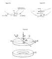
- a referential is defined with respect to micro-markings as illustrated in figures 79 and 80 , for a surface bearing micro-markings and for a surface not bearing the micro-markings respectively.
- Progressive lenses comprise micro-markings that have been made mandatory by a harmonized standard ISO 8990-2. Temporary markings may also be applied on the surface of the lens, indicating positions of control points on the lens, such as a control point for far vision, a control point for near vision, a prism reference point and a fitting cross for instance. If the temporary markings are absents or have been erased, it is always possible to a skilled person to position the control points on the lens by using a mounting chart and the permanent micro-markings. The lens manufacturer has to guarantee prescription at the control points.
- micro-markings also make it possible to define referential for both surfaces of the lens.
- Figure 79 shows the referential for the surface bearing the micro-markings.
- MG is the collinear unitary vector defined by the two micro-markings.
- vector Y of the referential is equal to the vector product of Z by MG;
- vector X of the referential is equal to the vector product of Y by Z. ⁇ X, Y, Z ⁇ thereby form a direct orthonormal trihedral.
- the X axis is the horizontal axis and the Y axis is the vertical axis.
- Figure 80 shows the referential for the surface opposite to the surface bearing the micro-markings.
- Referential of the second surface is constructed the same way as the referential of the first surface, i.e. vector Z is equal to the unitary normal of the second surface; vector Y is equal to the vector product of Z by MG; vector X is equal to the vector product of Y by Z.
- the X axis is the horizontal axis and the Y axis.
- a progressive multifocal lens may also be defined by optical characteristics, taking into consideration the situation of the person wearing the lenses.
- optical characteristics taking into consideration the situation of the person wearing the lenses.
- optical power and the astigmatism of the lens, in the wearing conditions can be calculated as explained in the article by B. Bourdoncle et al., entitled “Ray tracing through progressive ophthalmic lenses", 1990 International Lens Design Conference, D.T. Moore ed., Proc. Soc. Photo. Opt. Instrum. Eng. Wearing conditions may be calculated from a ray-tracing program, for a given lens. Further, the optical power and the astigmatism may be calculated so that the prescription is fulfilled for a wearer wearing his spectacles in the wearing conditions. Optical power and astigmatism can also be measured by a frontofocometer.
- Gaze directions are usually given by their degree of lowering and azimuth in a frame whose origin is the center of rotation of the eye.
- a point called the fitting cross is placed before the pupil or before the eye rotation center Q' of the eye for a primary gaze direction.
- the primary gaze direction corresponds to the situation where a wearer is looking straight ahead.
- the fitting cross corresponds thus to a lowering angle ⁇ of 0° and an azimuth angle ⁇ of 0° whatever surface of the lens the fitting cross is positioned - rear surface or front surface.
- the "upper" part of the surface of a lens - or of a semi-finished lens blank - corresponds to a positive value along the y axis, and preferably to a value along the y axis superior to the y_value at the fitting cross and the "lower" part of the surface of a lens - or of a semi-finished lens blank - corresponds to a negative value along the y axis in the frame as defined above with respect to figures 79 and 80 , and preferably to a value along the y axis inferior to the y_value at the fitting cross.
- the visual field zones seen through a lens are schematically illustrated in figure 81 .
- the lens comprises a far vision zone 26 located in the upper part of the lens, a near vision zone 28 located in the lower part of the lens and an intermediate zone 30 situated in the lower part of the lens between the far vision zone 26 and the near vision zone 28.
- the lens also has a main meridian 32 passing through the three zones and defining a nasal side and a temporal side.
- the far vision zone 26 includes a far vision control point FV
- the near vision zone 28 includes a near vision control point NV.
- the far vision zone and the near vision zone can be defined as the projection of the above defined zones on the surface.
- the far vision zone, respectively the near vision zone can be defined as the zones that contribute to the far vision field zone, respectively the near vision field zone, when the lens is used.
- all the gaze directions defined in that way form the meridian line of the ergorama-eye-lens system.
- the meridian line of the lens represents the locus of mean gaze directions of a wearer when he is looking from far to near visions.
- the meridian line 32 of a surface of the lens can be defined as follow: each gaze direction ( ⁇ , ⁇ ) belonging to the optical meridian line of the lens intersects the surface in a point (x, y).
- the meridian line of the surface is the set of points corresponding to the gaze directions of the meridian line of the lens.
- the meridian 32 separates the lens in a nasal area and a temporal area.
- the nasal area is the area of the lens which is between the meridian and the nose of the wearer whereas the temporal area is the area which is between the meridian and the temple of the wearer.
- the invention relies on a study by the applicant of the distortion. Notably, the applicant has established that a regressive front surface improves optical distortion in peripheral vision on the final lens. The applicant has observed that the more regressive the front surface was, the better the distortion was compensated.
- regressive surface is meant a continuous aspheric surface having a far vision zone, a near vision zone and a zone of decreasing mean sphere value connecting the far vision and near vision zones.
- progressive surface is meant a continuous aspheric surface having a far vision zone, a near vision zone and a zone of increasing mean sphere value connecting the far vision and near vision zones.
- the "addition of a surface” may be defined as the mean sphere variation between the near vision reference point (NV) belonging to the near vision zone and the far vision reference point (FV) belonging to the far vision zone.
- Reference points can be for instance, but not limited to, control points.
- the addition of the surface can be expressed as:
- this addition value will be called the maximum addition value of the surface.
- the regressive surface of the lens blank according to the invention has a mean sphere value in at least a portion of the far vision zone that is more than the mean sphere value in at least a portion of the near vision zone.
- the rear surface when the front surface is regressive, i.e. mean sphere value in at least a portion of the far vision zone is more than the mean sphere value in at least a portion of the near vision zone, the rear surface must have an even stronger addition to obtain a positive power addition on the final lens.
- the front surface should have a negative addition of about 3 diopters for instance, the rear surface should have a positive addition of about 5 diopters to ensure a positive power addition of about 2 diopters the lens.
- a grinding step is first performed wherein material is taken away from the surface of the lens to bring the surface as close as possible to the geometry requested to obtain the surface characteristics sought. Then a polishing step is performed to obtain a transparent surface while preserving the geometry obtained after grinding.
- the gradients tend to be filtered. Whenever gradients values vary sharply, the polishing step will soften this variation, which can lead to degradation of the surface obtained after polishing, notably along the meridian line.
- Figure 82 illustrates the positioning of a lens blank 10 in a reference frame of a lens blocking device 20 of a digital surfacing machine.
- the reference frame of the lens blank 10 in the blocker 20 can be defined by:
- An error in the positioning of the lens blank i.e. a translation and/or rotation will lead to surfacing a second surface with an offset with respect to the first surface and the optical performances of the final lens will not match the nominal performances (nominal performances being the theoretical performances of the lens considering no manufacturing errors).
- a method for compensating positioning error when manufacturing the lens is disclosed in WO-A-2010/072749 .
- a surface has a hard design, i.e. high gradients of sphere and cylinder and strong variations of gradients, even a slight error in positioning will result in stronger optical divergence between the optical performances of the lens and the nominal performances.
- the invention proposes a semi-finished lens blank with a regressive surface having a very soft design.
- a soft design will ensure that gradients do not change too drastically.
- the unfinished surface of the blank will be machined to fulfill a target optical design and the wearer's prescription, the values and variations of gradients of sphere and cylinder will also be better controlled.
- the invention also proposes a progressive lens with a front regressive surface having a very soft design.
- a first regressive surface of a semi-finished lens blank Still, the following description could be given in similar terms for the front regressive surface of a progressive lens.
- an aspherical surface may be locally defined by mean sphere and cylinder.
- Gradients of sphere and cylinder may also be defined.
- Cylinder is representative of how much the local surface deviates from a spherical surface. Variations in sphere lead of necessity to variations in cylinder, and cylinder cannot be nil over the whole lens surface.
- a fourth derivative with respect to altitude z may also be defined in each point of the aspherical surface.
- the fourth derivative D 4 is representative of the rapidity of change of the gradients values, i.e. acceleration of the sphere and cylinder variations.
- the invention proposes to control the value of the fourth derivative D 4 over the first surface of the lens blank. Such control will thus contribute to reduce significantly the possible degradation of the surface during the polishing step when machining the second surface of the lens and also when machining this first surface should digital surfacing technique be used as explained in more detail below.
- This quantity is controlled, at least over a central portion of the first surface of the lens blank.
- This central portion includes a portion of the main meridian, a reference point in the far vision zone and a reference point in the near vision zone.
- the reference points can be the control points defined above, but any other reference points could be chosen.
- the value of D 4 is controlled within a 40 mm diameter circle - ie within a 20 mm radius around the lens blank center; this amounts to excluding regions at the edge of a lens which are infrequently used by the lens wearer.
- Optical performances of the lens are typically considered within a central portion for directions of view comprised within a cone of +/-40° aperture centered on the center of rotation of the eye.
- the invention also proposes normalizing the value of the fourth derivative, to obtain a quantity which is not a function of the addition of the surface.
- the normalization factor involves the addition value.
- the invention proposes to set a limit value to the fourth derivative D 4 when determining the regressive surface of the semi-finished lens blank. More specifically, the normalized value of the fourth derivative D 4 is limited to 5.0.10 -5 mm -2 .diopter -1 over at least the central portion of the lens blank and preferably is limited to 3.5.10 -5 mm -2 .diopter -1 of the blank.
- the value of the fourth derivative D 4 can not be nil over this central portion and a minimal value of 1.0.10 -6 mm -2 .diopter -1 is to be expected.
- the normalization factor is equal to the maximum value of the addition of the surface.
- the invention also proposes to control the value of the sphere and cylinder gradients over the first surface of the lens blank. Such control will thus contribute to reduce significantly the possible degradation of the surface during the grinding step when machining the second surface of the lens, and also when machining this first surface should digital surfacing technique be used.
- Sphere and cylinder gradients are controlled, at least over a central portion of the first surface of the lens blank.
- the sphere and cylinder gradients are controlled within the 40 mm diameter circle defined above.
- the sphere and cylinder gradients limit values can be normalized to obtain a quantity which is not a function of the addition of the surface.
- the invention proposes to set a limit value to the sphere gradient when determining the regressive surface of the semi-finished lens blank. More specifically, the normalized value of the sphere gradient is limited to 7.50.10 -1 mm -1 over at least the central portion of the lens blank and preferably is limited to 6.50.10 -1 mm -1 over the central portion of the blank. However, the value of the sphere gradient can not be nil over this central portion and a minimal value of 1.0.10 -2 mm -1 is to be expected.
- the normalization factor is equal to the maximum value of the addition of the surface.
- the invention also proposes to set a limit value to the cylinder gradient when determining the regressive surface of the semi-finished lens blank. More specifically, the normalized value of the cylinder gradient is limited to 1.45 mm -1 over at least the central portion of the lens blank and preferably is limited to 1.25 mm -1 over the central portion of the blank. However, the value of the sphere gradient can not be nil over this central portion and a minimal value of 1.0.10 -2 mm -1 is to be expected.
- the normalization factor is equal to the maximum value of the addition of the surface.
- the x-axis corresponds to the horizontal axis of the lens and the y-axis to the vertical axis;
- the center O of the reference frame is the geometric center of the surface of the lens blank as defined with respect to figures 79 and 80 .
- the axes are graduated in millimeters.
- FIG. 1 to 25 are illustrations of surfaces of semi-finished lens blanks, i.e. front surfaces of the final lenses.
- FIG. 1 to 5 and 6 to 10 are illustrations of surfaces according to comparative examples outside the scope of the invention and
- FIG. 11 to 15 and 16 to 20 and 21 to 25 are illustrations of surfaces according to three examples of the invention.
- the five examples are given for a lens for a wearer whose prescription would be prescribed optical power in far vision of 0 diopter, prescribed astigmatism in far vision of 0 diopter and prescribed addition of 2.5 diopters for semi-finished lens blanks of 60 mm diameter.
- the mean sphere value at the far vision control point is 4.72 diopters.
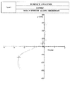
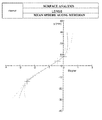
- FIG. 1 is a graph of mean sphere variation relatively to the mean sphere value of the far vision control point along the meridian for the surface of the first comparative example.
- the x-axis is graduated in diopters and y-axis values in mm.
- the far vision control point has a x-axis value of 0mm, a y-axis value of 8 mm on the surface, and has a sphere of 4.72 diopters and a cylinder of 0.02 diopters.
- the near vision control point has an x-axis value of 3mm, a y-axis value of -14 mm on the surface, and has a sphere of 2.20 diopters and a cylinder of 0.04 diopters.
- the nominal surface addition is -2.52 diopters, calculated as the difference between mean spheres at the control points.
- FIG. 6 is a graph of mean sphere variation relatively to the mean sphere value of the far vision control point along the meridian for the surface of the second comparative example.
- the x-axis is graduated in diopters and y-axis values in mm.
- the far vision control point has an x-axis value of 0mm, a y-axis value of 8 mm on the surface, and has a sphere of 4.72 diopters and a cylinder of 0.02 diopters.
- the near vision control point has an x-axis value of 3mm, a y-axis value of -14 mm on the surface, and has a sphere of 2.20 diopters and a cylinder of 0.06 diopters.
- the nominal surface addition is -2.52 diopters, calculated as the difference between mean spheres at the control points.
- FIG. 11 is a graph of mean sphere along the meridian for the surface according to a first example of the invention.
- the x-axis is graduated in diopters and y-axis values in mm.
- the far vision control point has an x-axis value of 0 mm, a y-axis value of 8 mm on the surface, and has a sphere of 4.72 diopters and a cylinder of 0.07 diopters.
- the near vision control point has an x-axis value of 3mm, a y-axis value of -14 mm on the surface, and has a sphere of 2.20 diopters and a cylinder of 0.08 diopters.
- the nominal surface addition is -2.51 diopters, calculated as the difference between mean spheres at the control points.
- FIG. 16 is a graph of mean sphere along the meridian for the surface according to a second example of the invention.
- the x-axis is graduated in diopters and y-axis values in mm.
- the far vision control point has an x-axis value of 0 mm, a y-axis value of 8 mm on the surface, and has a sphere of 4.72 diopters and a cylinder of 0.07 diopters.
- the near vision control point has an x-axis value of 3 mm, a y-axis value of -14 mm on the surface, and has a sphere of 2.20 diopters and a cylinder of 0.08 diopters.
- the nominal surface addition is -2.51 diopters, calculated as the difference between mean spheres at the control points.
- FIG. 21 is a graph of mean sphere along the meridian for the surface according to a third example of the invention.
- the x-axis is graduated in diopters and y-axis values in mm.
- the far vision control point has an x-axis value of 0 mm, a y-axis value of 8 mm on the surface, and has a sphere of 4.71 diopters and a cylinder of 0.10 diopters.
- the near vision control point has an x-axis value of 3 mm, a y-axis value of -14 mm on the surface, and has a sphere of 2.21 diopters and a cylinder of 0.10 diopters.
- the nominal surface addition is -2.50 diopters, calculated as the difference between mean spheres at the control points.
- the regression value is about the same for all surfaces but sphere variations in proximity of the control points are less strong on the surfaces according to the invention. More specifically the sharp variation of sphere and cylinder located near the control points have been smothered on the surfaces according to the invention, notably for the example of Lens 5.
- the maximum value of the fourth derivative D 4 defined above is representative of these sharp variations of sphere and cylinder. D 4 is directly linked to the acceleration of the sphere and cylinder.
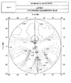
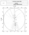
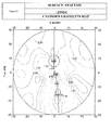
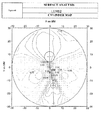
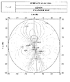
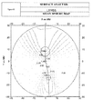
- FIG. 2 , 7 , 12 , 17 and 22 are maps showing mean sphere variation relatively to the mean sphere value of the far vision control point for the front surfaces of Lens 1, Lens 2, Lens 3, Lens 4 and Lens 5 respectively. These maps show the projection of the surface onto the (x, y) plane; the (x, y) reference frame defined above as well as the main meridian will be recognized.
- the control points for far and near vision have respective coordinates of (0; 8) and (3; -14).
- isosphere lines in other words lines joining points having the same mean sphere value can be seen. It can be observed that sphere gradients are much smaller, i.e. isosphere lines are more spaced apart, on the surfaces according to the invention by comparison to the surfaces of the comparative examples.
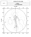
- FIG. 3 , 8 , 13 , 18 and 23 are maps of cylinder for the front surfaces of Lens 1, Lens 2, Lens 3, Lens 4 and Lens 5 respectively; the same graphical conventions and indications as those of FIG. 2 , 7 , 12 , 17 and 22 are used, simply showing cylinder in place of sphere in this drawing. It can be observed that cylinder gradients are much smaller, i.e. isocylinder lines are more spaced apart, on the surfaces according to the invention by comparison to the surfaces of the comparative examples.
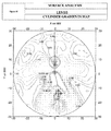
- FIG. 4 , 9 , 14 , 19 and 24 are maps of sphere gradients for the front surfaces of Lens 1, Lens 2, Lens 3, Lens 4 and Lens 5 respectively. These maps confirm that sphere gradients of the surfaces according to the invention are much less than the sphere gradients of surfaces of comparative examples which have a hard design. Notably, sphere gradient normalized to the nominal surface addition is less than 7.50.10 -1 mm -1 at any point in the circle of 40 mm centered on the central point O for the surfaces of the invention - taken note that the maps show the non normalized values of sphere gradients.
- FIG. 5 , 10 , 15 , 20 and 25 are maps of cylinder gradients for the front surfaces of Lens 1, Lens 2, Lens 3, Lens 4 and Lens 5 respectively. These maps confirm that cylinder gradients of the surface according to the invention are much less than the cylinder gradients of surfaces of comparative examples which have a hard design. Notably, cylinder gradient is less than 1.45 mm -1 at any point in the circle of 40 mm centered on the central point O for the surfaces of the invention - taken note that the maps show the non normalized values of sphere gradients.
- the maximum value of D 4 in the far vision zone is located near the far vision control point, i.e. at least 4 mm above the center of the surface along y-axis, and preferably at least 8 mm above the center of the surface along y-axis.
- the maximum value of D 4 in the near vision zone is located below the near vision control point, i.e. at least 8 mm below the center of the surface, and preferably at least 14 mm below the center of the surface.
- the gradients variations will be smaller on the central portion of the first surface of the semi-finished lens blank.
- the maximum value of D 4 of the calculated rear surface will also be smaller and the surfacing will be more accurate.
- Table I summarizes the normalized maximum values of fourth derivative D 4 , sphere gradient and cylinder gradient for the front surfaces of the lenses considered.
- Table I Front Surface Criteria D4 (mm -2 .diopter -1 ) Grad SPH (mm -1 ) Grad CYL (mm -1 ) Lens 1 6.90.10 -5 9.23.10 -1 1.74 Lens 2 5.52.10 -5 7.96.10 -1 1.55 Lens 3 4.14.10 -5 6.96.10 -1 1.35 Lens 4 2.84.10 -5 6.01.10 -1 1.17 Lens 5 2.36.10 -5 5.12.10 -1 9.97.10 -1
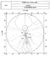
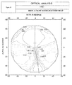
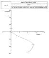
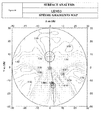
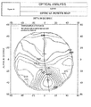
- FIG. 26 to 40 are optical analyses of the nominal performance of the lenses considered. Nominal performances are defined as the selected best compromise resulting from the repartition of optical defects over the lens. A target optical function is then defined to be used during optical optimization when defining the surfaces characteristics of the lens. The manufactured lens finally obtained may have optical performances slightly deviating from the nominal performances, due notably to machining limitations and positioning defects.
- FIG. 26 , 29 , 32 , 35 , 38 represent nominal power along the main meridian for lenses Lens 1, Lens 2, Lens 3, Lens 4 and Lens 5 respectively.
- the optical addition is 2.69 diopters for Lens 1 and Lens 2; 2.67 diopters for Lens 3; 2.66 diopters for Lens 4 and Lens 5, power at the far vision control point being nil. It is immediately apparent that the optical performances along the meridian are the same for all lenses.
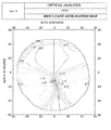
- FIG. 27 , 30 , 33 , 36 and 39 show nominal power perceived by the wearer with lenses Lens 1, Lens 2, Lens 3, Lens 4 and Lens 5 respectively.
- FIG. 28 , 31 , 34 , 37 and 40 show resulting astigmatism for with lenses Lens 1, Lens 2, Lens 3, Lens 4 and Lens 5 respectively. It is immediately apparent that the optical performances are substantially the same for all lenses.
- Using a semi-finished lens blank according to the invention allows an easier lens manufacturing while maintaining the optical performances of the lens as it will be now explained.
- FIG. 41 to 65 are illustrations of a second surface for lenses manufactured from lens blanks of FIG.1 to 25 , i.e. rear surfaces of the lenses considered Lens 1, Lens 2, Lens 3, Lens 4 and Lens 5.
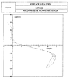
- FIG. 41 , 46 , 51 , 56 and 61 are graphs of mean sphere variation along the meridian for the rear surfaces of Lens 1, Lens 2, Lens 3, Lens 4 and Lens 5 respectively.
- the nominal surface power progression is 4.76 diopters for Lens 1 and Lens 2, 4.77 diopters for Lens 3, Lens 4 and Lens 5, calculated as the difference between mean spheres at the control points.
- FIG. 42 , 47 , 52 , 57 and 62 are maps showing mean sphere variation relatively to the mean sphere value of the far vision control point for the rear surfaces of Lens 1, Lens 2, Lens 3, Lens 4 and Lens 5 respectively.
- FIG. 43 , 48 , 53 , 58 and 63 are maps showing cylinder for the rear surfaces of Lens 1, Lens 2, Lens 3, Lens 4 and Lens 5 respectively.
- FIG. 44 , 49 , 54 , 59 and 64 are maps showing sphere gradients for the rear surfaces of Lens 1, Lens 2, Lens 3, Lens 4 and Lens 5 respectively and
- FIG. 45 , 50 , 55 , 60 and 65 are maps showing cylinder gradients for the rear surfaces of Lens 1, Lens 2, Lens 3, Lens 4 and Lens 5 respectively.
- Table II summarizes the normalized maximum values of fourth derivative D 4 , sphere gradient and cylinder gradient for the rear surfaces of the lenses considered.
- Table II Rear Surface Criteria D4 (mm -2 .diopter -1 ) Grad SPH (mm -1 ) Grad CYL (mm -1 ) Lens 1 1.49.10 -4 1.87 3.57 Lens 2 1.35.10 -4 1.74 3.38 Lens 3 1.20.10 -4 1.60 3.18 Lens 4 1.05.10 -4 1.48 2.98 Lens 5 9.13.10 -5 1.38 2.79
- a semi-finished blank according to the invention with a soft design and controlled values of fourth derivative, makes it easier to manufacture the lens and further improves the optical quality of the lens obtained after surfacing the second surface.
- nominal optical performances are substantially the same for all lenses. Still the lenses of the invention are more tolerant to positioning defects during manufacturing.
- FIG. 69 to 71 are optical performances of Lens 5 with same simulated positioning defects.
- FIG. 72 to 74 are superposition of the nominal optical performances and the simulated optical performances with positioning defects for Lens 1, i.e. superposition of FIG. 26 to 28 and FIG. 66 to 68 .
- FIG. 75 to 77 are superposition of the nominal optical performances and the simulated optical performances with positioning defects for Lens 5, i.e. superposition of FIG. 38 to 40 and FIG.
- FIG. 78 is a graph showing the maximal deviation between nominal performances and simulated optical performances with positioning defects for each lens considered. The impact of positioning defects was evaluated over a central portion of the lens, and notably for directions of view -40° ⁇ 40° and -40° ⁇ 40°. To provide the graph of FIG. 78 , the deviation between nominal power/resultant astigmatism and simulated power/resultant astigmatism was calculated for each direction of view in the central portion defined above for each lens; then the maximum deviation was evaluated from among the deviation values for all directions of view in the central portion of the lens.
- lenses having a front regressive surface according to the invention have lesser deviation from nominal performances that lenses having front regressive surface according to comparative examples even though same positioning defects have been simulated.
- lenses manufactured from a lens blank according to the invention will have enhanced optical quality once manufactured.
- the maximum values set for sphere gradients, cylinder gradients and fourth derivative when defining the regressive front surface of the lens ensure that the rear surface can be manufactured without creating to much defects - during grinding and polishing as explained above - but also ensure that small positioning defects only slightly impact the optical performances of the manufactured lens - acuity of the wearer is not truly affected.
- Table III summarizes the maximum deviation values of mean power ⁇ P and resultant astigmatism ⁇ A of the lenses considered and gives the resulting acuity reduction according to a relation given in the publication by Fauquier et al. cited above.
- Table III ⁇ P (diopters) ⁇ A (diopters) AC (%) Lens1 0,31 0,39 33,6 Lens2 0,29 0,36 31,4 Lens3 0,26 0,32 28,3 Lens4 0,24 0,3 26,5 Lens5 0,22 0,27 24,2
- Applicant regards an acuity reduction AC(%) of 30% as being discriminative.
- the normalized limit value of 5.0.10 -5 mm -2 .diopter -1 for the fourth derivative D 4 and/or the limit values of 7.5.10 -1 mm -1 /1.45 mm -1 for the sphere/cylinder gradients over at least a central portion of the front regressive surface provide that the lens can be easily manufactured while fulfilling the nominal optical performances.
- the semi-finished lens blank of the invention may be manufactured by digital surfacing or moulding.
- the first surface of the semi-finished lens blank is determined by setting a regression of the mean sphere value between the far vision zone 26 and the near visions zone 28, and a fourth derivative with respect to altitude D 4 value less than 5.0.10 -5 mm -2 .diopter -1 at any point in a central portion.
- Other criteria as defined above, notably limit values of sphere gradients and cylinder gradients, may also be used when determining the first surface of the semi-finished lens blank.
- Data relative to the determined first surface will be used to control machining of a mould or to control a digital surfacing machine to produce the first surface of the semi-finished lens blank.
- a progressive lens can be manufactured using a semi-finished lens blank according to the invention.
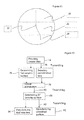
- FIG. 83 is a flowchart of an example of the steps that can be carried out for manufacturing a progressive ophthalmic lens according to the invention.
- Data relative to a wearer are provided (step 74). This can be done at a first location, i.e. a spectacle seller (optician).
- the data are transmitted (step 75) from the first location to a second location where a semi-finished lens blank is selected (step 77) and where an optical optimization of the lens based on the data relative to the wearer and on data relative to the first regressive surface of the semi-finished lens blank is carried out (step 78).
- This can be done in a laboratory of a lens designer.
- the semi-finished lens blank can be selected based on the wearer data, for instance the prescribed addition.
- the result of the optical optimization are transmitted (step 80) and a second surface of the lens is determined (step 81) according to the result of the optical optimization.
- the data relative to the second surface are transmitted (step 82) to a lens manufacturer.
- the lens manufacturer surfaces the unfinished surface of the blank according to the determined second surface (step 83).
- the unfinished surface of the blank can be made by digital surfacing or molding.
- the progressive lens of the invention can also be manufactured without using a semi-finished lens blank.
- Data relative to a wearer are provided (step 74).
- the data are transmitted (step 75) from the first location to a second location where a first surface is determined (step 76).
- the first surface is determined using the criteria defined previously, and notably, a regression of the mean sphere value between at least a portion of the far vision zone 26 and at least a portion of the near visions zone 28, a sphere gradient value less than 7.50.10 -1 mm -1 at any point in a central portion of the lens, a cylinder gradient value less than 1.45 mm -1 at any point in the central portion of the lens and a fourth derivative with respect to altitude (D 4 ) value less than 5.10 -5 mm 2 .diopter -1 at any point in the central portion of the lens.
- the data relative to the first surface are transmitted and an optical optimization of the lens based on the data relative to the wearer and on data relative to the first surface is carried out (step 78). This can be done in the same laboratory as the determination of the first surface, or in a different laboratory.
- the results of the optical optimization are transmitted (step 80) and a second surface of the lens is determined (step 81) according to the result of the optical optimization. This can still be done in the same laboratory, or in a different laboratory.
- the data relative to the first and second surface are transmitted (step 82) to a lens manufacturer and the lens is produced by double side digital surfacing (step 84) or by molding.
- Computer program products can be provided comprising one or more stored sequence of instruction that is accessible to a processor and which, when executed by the processor, causes the processor to carry out the steps of the methods are also proposed.
- Such computer programs may be stored in a computer readable storage medium, such as, but is not limited to, any type of disk including floppy disks, optical disks, CD-ROMs, magnetic-optical disks, read-only memories (ROMs), random access memories (RAMs) electrically programmable read-only memories (EPROMs), electrically erasable and programmable read only memories (EEPROMs), magnetic or optical cards, or any other type of media suitable for storing electronic instructions, and capable of being coupled to a computer system bus.
- a computer-readable medium carrying one or more sequences of instructions of the computer program product is thus proposed. This enables to carry out the method in any location.
- a set of apparatuses for manufacturing a progressive ophthalmic lens, wherein the apparatuses are adapted to carry out the method for manufacturing is also proposed.
Priority Applications (14)
| Application Number | Priority Date | Filing Date | Title |
|---|---|---|---|
| EP11305381A EP2506063A1 (fr) | 2011-03-31 | 2011-03-31 | Lentille ophtalmique progressive |
| CN201280016184.XA CN103460117B (zh) | 2011-03-31 | 2012-03-22 | 渐进眼镜片 |
| PCT/EP2012/055146 WO2012130736A2 (fr) | 2011-03-31 | 2012-03-22 | Lentille ophtalmologique progressive |
| ES12710088.1T ES2657857T3 (es) | 2011-03-31 | 2012-03-22 | Lente oftálmica progresiva |
| BR112013024787-8A BR112013024787B1 (pt) | 2011-03-31 | 2012-03-22 | lente oftálmica progressiva, modelo de lente de óculos semiacabado, método para fabricar modelo de lente semiacabada e método para fabricar uma lente oftálmica progressiva |
| IN8611CHN2013 IN2013CN08611A (fr) | 2011-03-31 | 2012-03-22 | |
| RU2013148568/28A RU2589295C2 (ru) | 2011-03-31 | 2012-03-22 | Прогрессивная офтальмологическая линза |
| AU2012234416A AU2012234416B2 (en) | 2011-03-31 | 2012-03-22 | Progressive ophthalmic lens |
| JP2014501550A JP6069296B2 (ja) | 2011-03-31 | 2012-03-22 | 累進多焦点眼用レンズ |
| US14/007,721 US9454019B2 (en) | 2011-03-31 | 2012-03-22 | Progressive ophthalmic lens |
| EP12710088.1A EP2691806B1 (fr) | 2011-03-31 | 2012-03-22 | Lentille ophtalmologique progressive |
| CA2830638A CA2830638C (fr) | 2011-03-31 | 2012-03-22 | Lentille ophtalmologique progressive |
| KR1020137025217A KR101902372B1 (ko) | 2011-03-31 | 2012-03-22 | 누진 안경 렌즈 |
| ZA2013/06748A ZA201306748B (en) | 2011-03-31 | 2013-09-09 | Progressive ophthalmic lens |
Applications Claiming Priority (1)
| Application Number | Priority Date | Filing Date | Title |
|---|---|---|---|
| EP11305381A EP2506063A1 (fr) | 2011-03-31 | 2011-03-31 | Lentille ophtalmique progressive |
Publications (1)
| Publication Number | Publication Date |
|---|---|
| EP2506063A1 true EP2506063A1 (fr) | 2012-10-03 |
Family
ID=44351805
Family Applications (2)
| Application Number | Title | Priority Date | Filing Date |
|---|---|---|---|
| EP11305381A Withdrawn EP2506063A1 (fr) | 2011-03-31 | 2011-03-31 | Lentille ophtalmique progressive |
| EP12710088.1A Active EP2691806B1 (fr) | 2011-03-31 | 2012-03-22 | Lentille ophtalmologique progressive |
Family Applications After (1)
| Application Number | Title | Priority Date | Filing Date |
|---|---|---|---|
| EP12710088.1A Active EP2691806B1 (fr) | 2011-03-31 | 2012-03-22 | Lentille ophtalmologique progressive |
Country Status (13)
| Country | Link |
|---|---|
| US (1) | US9454019B2 (fr) |
| EP (2) | EP2506063A1 (fr) |
| JP (1) | JP6069296B2 (fr) |
| KR (1) | KR101902372B1 (fr) |
| CN (1) | CN103460117B (fr) |
| AU (1) | AU2012234416B2 (fr) |
| BR (1) | BR112013024787B1 (fr) |
| CA (1) | CA2830638C (fr) |
| ES (1) | ES2657857T3 (fr) |
| IN (1) | IN2013CN08611A (fr) |
| RU (1) | RU2589295C2 (fr) |
| WO (1) | WO2012130736A2 (fr) |
| ZA (1) | ZA201306748B (fr) |
Cited By (7)
| Publication number | Priority date | Publication date | Assignee | Title |
|---|---|---|---|---|
| PT11124T (pt) * | 2015-02-10 | 2015-08-10 | Antonio Manuel Caeiro Boga | Lente de óculos para pessoas diabéticas |
| WO2017064037A1 (fr) * | 2015-10-15 | 2017-04-20 | Essilor International (Compagnie Generale D'optique) | Verre ophtalmique à foyer progressif pour porteur hypermétrope et presbyte, et procédé de fabrication d'un tel verre |
| WO2017064030A1 (fr) * | 2015-10-15 | 2017-04-20 | Essilor International (Compagnie Generale D'optique) | Lentille à addition progressive ophtalmique pour un porteur myope et presbyte, et procédé de production d'une telle lentille |
| WO2017064055A1 (fr) * | 2015-10-15 | 2017-04-20 | Essilor International (Compagnie Generale D'optique) | Verre ophtalmique à foyer progressif pour porteur presbyte, et procédé pour la de fabrication d'un tel verre |
| WO2017064032A1 (fr) * | 2015-10-15 | 2017-04-20 | Essilor International (Compagnie Generale D'optique) | Verre ophtalmique à foyer progressif destiné à un porteur emmétrope et presbyte, et procédé de fabrication d'un tel verre |
| WO2017064041A1 (fr) * | 2015-10-15 | 2017-04-20 | Essilor International (Compagnie Generale D'optique) | Verre ophtalmique à foyer progressif pour porteur myope ou emmétrope presbyte, et procédé de fabrication d'un tel verre |
| WO2022161944A1 (fr) * | 2021-01-29 | 2022-08-04 | Rodenstock Gmbh | Système et procédé de traitement d'entrée de commande et fabrication de verres de lunettes |
Families Citing this family (15)
| Publication number | Priority date | Publication date | Assignee | Title |
|---|---|---|---|---|
| SG11201405687QA (en) * | 2012-03-14 | 2014-11-27 | Holden Brien Vision Inst | Lens for myopic eye |
| EP2648032A1 (fr) * | 2012-04-02 | 2013-10-09 | Essilor Canada Ltee | Surface ophtalmique progressive |
| CN104995548B (zh) * | 2013-02-20 | 2017-04-12 | 依视路国际集团(光学总公司) | 一副渐进式眼镜片 |
| US9740024B2 (en) * | 2013-02-20 | 2017-08-22 | Essilor International (Compagnie Generale D'optique) | Pair of progressive ophthamlic lenses |
| US9952584B2 (en) | 2014-04-01 | 2018-04-24 | Digital Vision, Inc. | Modifying a digital ophthalmic lens map to accommodate characteristics of a lens surfacing machine |
| US9671624B2 (en) * | 2014-04-01 | 2017-06-06 | Digital Vision, Inc. | Optical lens processing system, such as a system for providing lens design source information to users |
| EP3656350B1 (fr) * | 2016-03-23 | 2021-06-23 | Johnson & Johnson Surgical Vision, Inc. | Appareil ophtalmique doté de méridiens de correction possédant une bande de tolérance étendue en modifiant les puissances de réfraction dans une distribution de méridiens uniforme |
| EP3932368A1 (fr) | 2016-03-23 | 2022-01-05 | Johnson & Johnson Surgical Vision, Inc. | Appareil ophtalmique à méridiens correctifs présentant une bande de tolérance étendue |
| EP3522771B1 (fr) | 2016-10-25 | 2022-04-06 | Amo Groningen B.V. | Modèles oculaires réalistes pour modéliser et évaluer des lentilles intraoculaires pour un grand champ de vision |
| US10739227B2 (en) | 2017-03-23 | 2020-08-11 | Johnson & Johnson Surgical Vision, Inc. | Methods and systems for measuring image quality |
| ES2687223A1 (es) * | 2017-04-21 | 2018-10-24 | Horizons Optical S.L.U. | Procedimiento de optimización de una lente oftálmica progresiva y procedimiento de fabricación de la misma. |
| EP3692411A1 (fr) * | 2017-10-03 | 2020-08-12 | Essilor International | Procédé permettant d'évaluer une lentille ophtalmique ; système d'évaluation associé et ensemble industriel de fabrication d'une lentille ophtalmique |
| EP3483681B1 (fr) * | 2017-11-08 | 2023-08-30 | Essilor International | Procédé et système de production de lentilles ophtalmiques |
| WO2019106067A1 (fr) | 2017-11-30 | 2019-06-06 | Amo Groningen B.V. | Lentilles intraoculaires permettant d'améliorer l'indépendance vis à vis des lunettes après une intervention chirurgicale et leurs procédés de fabrication |
| US10634935B2 (en) | 2018-01-18 | 2020-04-28 | Digital Vision, Inc. | Multifocal lenses with ocular side lens segments |
Citations (9)
| Publication number | Priority date | Publication date | Assignee | Title |
|---|---|---|---|---|
| EP0578833A1 (fr) * | 1992-02-03 | 1994-01-19 | Seiko Epson Corporation | Appareil de correction de puissance visuelle a foyer variable |
| EP0927377A1 (fr) | 1996-09-20 | 1999-07-07 | ESSILOR INTERNATIONAL (Compagnie Générale d'Optique) | Jeu de lentilles ophtalmiques multifocales progressives |
| EP0990939A1 (fr) | 1998-09-28 | 2000-04-05 | Essilor International Compagnie Generale D'optique | Lentilles ophtalmiques toriques |
| WO2000072051A2 (fr) * | 1999-05-25 | 2000-11-30 | Johnson & Johnson Vision Care, Inc. | Lentilles progressives a profils de puissance de canal modifies |
| EP1688781A1 (fr) * | 2005-02-04 | 2006-08-09 | Seiko Epson Corporation | Verre de lunettes combiné, verre additionnel, et procédé de débordage des verres |
| WO2008089996A1 (fr) * | 2007-01-25 | 2008-07-31 | Rodenstock Gmbh | Optimiseur flexible de verres progressifs |
| WO2010072749A1 (fr) | 2008-12-22 | 2010-07-01 | Essilor International (Compagnie Generale D'optique) | Procédé et appareil de fabrication d'une lentille optique |
| WO2010093664A1 (fr) * | 2009-02-12 | 2010-08-19 | Pixeloptics, Inc. | Lentilles ophtalmiques avec caractéristiques optiques asphériques |
| WO2010100528A1 (fr) | 2009-03-05 | 2010-09-10 | Essilor International (Compagnie Generale D'optique) | Lunettes pour enfant myope |
Family Cites Families (11)
| Publication number | Priority date | Publication date | Assignee | Title |
|---|---|---|---|---|
| US4861153A (en) * | 1986-12-19 | 1989-08-29 | American Optical Corporation | Progressive addition spectacle lens |
| US5715032A (en) * | 1996-03-19 | 1998-02-03 | Optical Radiation Corporation | Progressive addition power ophthalmic lens |
| JP4059274B2 (ja) * | 1996-10-14 | 2008-03-12 | セイコーエプソン株式会社 | 累進多焦点レンズの製造装置 |
| FR2769997B1 (fr) * | 1997-10-16 | 1999-12-31 | Essilor Int | Lentille ophtalmique multifocale |
| FR2788861B1 (fr) * | 1999-01-22 | 2001-03-30 | Essilor Int | Lentille ophtalmique multifocale progressive |
| US6139148A (en) * | 1999-02-04 | 2000-10-31 | Johnson & Johnson Vision Care, Inc. | Progressive addition lenses having regressive surfaces |
| JP2000258732A (ja) * | 1999-03-04 | 2000-09-22 | Seiko Epson Corp | 眼鏡レンズ及びその製造方法 |
| FR2809193B1 (fr) * | 2000-05-16 | 2002-08-09 | Essilor Int | Lentille ophtalmique multifocale progressive a variation de puissance rapide |
| FR2895092B1 (fr) * | 2005-12-16 | 2008-02-29 | Essilor Int | Procede de determination d'une lentille ophtalmique. |
| EP2028529B1 (fr) * | 2007-12-28 | 2020-09-09 | Essilor International | Procédé de calcul d'un système optique selon une monture de lunettes donné |
| JP5346503B2 (ja) * | 2008-06-20 | 2013-11-20 | 株式会社ニコン・エシロール | 累進屈折力レンズ及びその製造方法 |
-
2011
- 2011-03-31 EP EP11305381A patent/EP2506063A1/fr not_active Withdrawn
-
2012
- 2012-03-22 US US14/007,721 patent/US9454019B2/en active Active
- 2012-03-22 RU RU2013148568/28A patent/RU2589295C2/ru active
- 2012-03-22 ES ES12710088.1T patent/ES2657857T3/es active Active
- 2012-03-22 BR BR112013024787-8A patent/BR112013024787B1/pt active IP Right Grant
- 2012-03-22 AU AU2012234416A patent/AU2012234416B2/en active Active
- 2012-03-22 KR KR1020137025217A patent/KR101902372B1/ko active IP Right Grant
- 2012-03-22 JP JP2014501550A patent/JP6069296B2/ja active Active
- 2012-03-22 CA CA2830638A patent/CA2830638C/fr active Active
- 2012-03-22 CN CN201280016184.XA patent/CN103460117B/zh active Active
- 2012-03-22 IN IN8611CHN2013 patent/IN2013CN08611A/en unknown
- 2012-03-22 EP EP12710088.1A patent/EP2691806B1/fr active Active
- 2012-03-22 WO PCT/EP2012/055146 patent/WO2012130736A2/fr active Application Filing
-
2013
- 2013-09-09 ZA ZA2013/06748A patent/ZA201306748B/en unknown
Patent Citations (9)
| Publication number | Priority date | Publication date | Assignee | Title |
|---|---|---|---|---|
| EP0578833A1 (fr) * | 1992-02-03 | 1994-01-19 | Seiko Epson Corporation | Appareil de correction de puissance visuelle a foyer variable |
| EP0927377A1 (fr) | 1996-09-20 | 1999-07-07 | ESSILOR INTERNATIONAL (Compagnie Générale d'Optique) | Jeu de lentilles ophtalmiques multifocales progressives |
| EP0990939A1 (fr) | 1998-09-28 | 2000-04-05 | Essilor International Compagnie Generale D'optique | Lentilles ophtalmiques toriques |
| WO2000072051A2 (fr) * | 1999-05-25 | 2000-11-30 | Johnson & Johnson Vision Care, Inc. | Lentilles progressives a profils de puissance de canal modifies |
| EP1688781A1 (fr) * | 2005-02-04 | 2006-08-09 | Seiko Epson Corporation | Verre de lunettes combiné, verre additionnel, et procédé de débordage des verres |
| WO2008089996A1 (fr) * | 2007-01-25 | 2008-07-31 | Rodenstock Gmbh | Optimiseur flexible de verres progressifs |
| WO2010072749A1 (fr) | 2008-12-22 | 2010-07-01 | Essilor International (Compagnie Generale D'optique) | Procédé et appareil de fabrication d'une lentille optique |
| WO2010093664A1 (fr) * | 2009-02-12 | 2010-08-19 | Pixeloptics, Inc. | Lentilles ophtalmiques avec caractéristiques optiques asphériques |
| WO2010100528A1 (fr) | 2009-03-05 | 2010-09-10 | Essilor International (Compagnie Generale D'optique) | Lunettes pour enfant myope |
Non-Patent Citations (2)
| Title |
|---|
| "Ophthalmic and Visual Optics Technical Digest", vol. L, 1995, OPTICAL SOCIETY OF AMERICA, article "Influence of combined power error and astigmatism on visual acuity", pages: 151 - 154 |
| B. BOURDONCLE ET AL.: "International Lens Design Conference", 1990, PROC. SOC. PHOTO. OPT. INSTRUM. ENG, article "Ray tracing through progressive ophthalmic lenses" |
Cited By (15)
| Publication number | Priority date | Publication date | Assignee | Title |
|---|---|---|---|---|
| PT11124T (pt) * | 2015-02-10 | 2015-08-10 | Antonio Manuel Caeiro Boga | Lente de óculos para pessoas diabéticas |
| PT11124U (pt) * | 2015-02-10 | 2016-03-15 | Manuel Caeiro Boga Antonio | Lente de óculos para pessoas diabéticas |
| WO2017064037A1 (fr) * | 2015-10-15 | 2017-04-20 | Essilor International (Compagnie Generale D'optique) | Verre ophtalmique à foyer progressif pour porteur hypermétrope et presbyte, et procédé de fabrication d'un tel verre |
| WO2017064030A1 (fr) * | 2015-10-15 | 2017-04-20 | Essilor International (Compagnie Generale D'optique) | Lentille à addition progressive ophtalmique pour un porteur myope et presbyte, et procédé de production d'une telle lentille |
| WO2017064055A1 (fr) * | 2015-10-15 | 2017-04-20 | Essilor International (Compagnie Generale D'optique) | Verre ophtalmique à foyer progressif pour porteur presbyte, et procédé pour la de fabrication d'un tel verre |
| WO2017064032A1 (fr) * | 2015-10-15 | 2017-04-20 | Essilor International (Compagnie Generale D'optique) | Verre ophtalmique à foyer progressif destiné à un porteur emmétrope et presbyte, et procédé de fabrication d'un tel verre |
| WO2017064041A1 (fr) * | 2015-10-15 | 2017-04-20 | Essilor International (Compagnie Generale D'optique) | Verre ophtalmique à foyer progressif pour porteur myope ou emmétrope presbyte, et procédé de fabrication d'un tel verre |
| KR20180063883A (ko) * | 2015-10-15 | 2018-06-12 | 에씰로 앙터나시오날 | 근시 또는 정시 노안 착용자를 위한 안과용 누진 가법 렌즈 및 그러한 렌즈를 제공하는 방법 |
| US10690938B2 (en) | 2015-10-15 | 2020-06-23 | Essilor International | Ophthalmic progressive addition lens for a myopic or emmetropic presbyopic wearer; method for providing such a lens |
| US10712590B2 (en) | 2015-10-15 | 2020-07-14 | Essilor International | Opthalmic progressive addition lens for a presbyopic wearer; method for providing such a lens |
| US10852565B2 (en) | 2015-10-15 | 2020-12-01 | Essilor International | Ophthalmic progressive addition lens for a myopic and presbyopic wearer and method for providing same |
| US10852563B2 (en) | 2015-10-15 | 2020-12-01 | Essilor International | Ophthalmic progressive addition lens for an emmetropic and presbyopic wearer and method of providing same |
| US11067830B2 (en) | 2015-10-15 | 2021-07-20 | Essilor International | Ophthalmic progressive addition lens for a farsighted and presbyopic wearer; method for providing such a lens |
| AU2016338456B2 (en) * | 2015-10-15 | 2021-09-02 | Essilor International | An ophthalmic progressive addition lens for a myopic and presbyopic wearer; method for providing such a lens |
| WO2022161944A1 (fr) * | 2021-01-29 | 2022-08-04 | Rodenstock Gmbh | Système et procédé de traitement d'entrée de commande et fabrication de verres de lunettes |
Also Published As
| Publication number | Publication date |
|---|---|
| IN2013CN08611A (fr) | 2015-08-21 |
| BR112013024787A2 (pt) | 2016-12-27 |
| CN103460117B (zh) | 2015-12-09 |
| JP2014512023A (ja) | 2014-05-19 |
| RU2013148568A (ru) | 2015-05-10 |
| BR112013024787A8 (pt) | 2018-08-14 |
| CA2830638C (fr) | 2018-07-24 |
| CN103460117A (zh) | 2013-12-18 |
| CA2830638A1 (fr) | 2012-10-04 |
| KR101902372B1 (ko) | 2018-09-28 |
| JP6069296B2 (ja) | 2017-02-01 |
| US9454019B2 (en) | 2016-09-27 |
| US20140016088A1 (en) | 2014-01-16 |
| BR112013024787B1 (pt) | 2020-10-13 |
| AU2012234416B2 (en) | 2015-06-11 |
| RU2589295C2 (ru) | 2016-07-10 |
| ZA201306748B (en) | 2015-03-25 |
| EP2691806B1 (fr) | 2017-11-15 |
| EP2691806A2 (fr) | 2014-02-05 |
| KR20140015399A (ko) | 2014-02-06 |
| WO2012130736A2 (fr) | 2012-10-04 |
| AU2012234416A1 (en) | 2013-09-26 |
| WO2012130736A3 (fr) | 2012-11-22 |
| ES2657857T3 (es) | 2018-03-07 |
Similar Documents
| Publication | Publication Date | Title |
|---|---|---|
| EP2691806B1 (fr) | Lentille ophtalmologique progressive | |
| US7413303B2 (en) | Ophthalmic lens | |
| US7419261B2 (en) | Non-corrective lenses with improved peripheral vision | |
| EP3230792B1 (fr) | Procédé mis en oeuvre par ordinateur pour le calcul d'un système optique de lentille d'une lentille ophtalmique de lunettes destinée à un utilisateur | |
| JP2008501990A (ja) | 眼用レンズ | |
| EP2780759B1 (fr) | Procédé pour fournir un système optique d'un verre de lunette ophtalmique et procédé de fabrication de verre de lunette ophtalmique | |
| KR102100726B1 (ko) | 안과용 렌즈의 광학 파라미터 결정 방법 | |
| EP2667241B1 (fr) | Procédé de fabrication d'un verre de lunettes fournissant une correction astigmate et lunettes comprenant un tel verre de lunettes | |
| EP2791730B1 (fr) | Procédés permettant de déterminer une lentille ophtalmique progressive et ensemble d'ébauches de verre semi-fini | |
| EP2920640B1 (fr) | Procédé de détermination de la faisabilité d'un verre ophtalmique | |
| US20140320803A1 (en) | Method For Providing An Optical System Of An Ophthalmic Spectacle Lens And Method For Manufacturing An Ophthalmic Spectacle Lens | |
| EP2780761B1 (fr) | Procédé pour fournir un système optique d'un verre de lunette ophtalmique et procédé de fabrication de verre de lunette ophtalmique |
Legal Events
| Date | Code | Title | Description |
|---|---|---|---|
| PUAI | Public reference made under article 153(3) epc to a published international application that has entered the european phase |
Free format text: ORIGINAL CODE: 0009012 |
|
| AK | Designated contracting states |
Kind code of ref document: A1 Designated state(s): AL AT BE BG CH CY CZ DE DK EE ES FI FR GB GR HR HU IE IS IT LI LT LU LV MC MK MT NL NO PL PT RO RS SE SI SK SM TR |
|
| AX | Request for extension of the european patent |
Extension state: BA ME |
|
| 17P | Request for examination filed |
Effective date: 20130403 |
|
| D17P | Request for examination filed (deleted) | ||
| STAA | Information on the status of an ep patent application or granted ep patent |
Free format text: STATUS: THE APPLICATION IS DEEMED TO BE WITHDRAWN |
|
| 18D | Application deemed to be withdrawn |
Effective date: 20130404 |