EP2506039A2 - Methods for Seismic Fracture Parameter Estimation and Gas Filled Fracture Identification From Vertical Well Log Data - Google Patents
Methods for Seismic Fracture Parameter Estimation and Gas Filled Fracture Identification From Vertical Well Log Data Download PDFInfo
- Publication number
- EP2506039A2 EP2506039A2 EP12160883A EP12160883A EP2506039A2 EP 2506039 A2 EP2506039 A2 EP 2506039A2 EP 12160883 A EP12160883 A EP 12160883A EP 12160883 A EP12160883 A EP 12160883A EP 2506039 A2 EP2506039 A2 EP 2506039A2
- Authority
- EP
- European Patent Office
- Prior art keywords
- fracture
- wave
- vertical
- seismic
- methods
- Prior art date
- Legal status (The legal status is an assumption and is not a legal conclusion. Google has not performed a legal analysis and makes no representation as to the accuracy of the status listed.)
- Withdrawn
Links
Images


Classifications
-
- G—PHYSICS
- G01—MEASURING; TESTING
- G01V—GEOPHYSICS; GRAVITATIONAL MEASUREMENTS; DETECTING MASSES OR OBJECTS; TAGS
- G01V1/00—Seismology; Seismic or acoustic prospecting or detecting
- G01V1/40—Seismology; Seismic or acoustic prospecting or detecting specially adapted for well-logging
- G01V1/44—Seismology; Seismic or acoustic prospecting or detecting specially adapted for well-logging using generators and receivers in the same well
- G01V1/48—Processing data
- G01V1/50—Analysing data
-
- G—PHYSICS
- G01—MEASURING; TESTING
- G01V—GEOPHYSICS; GRAVITATIONAL MEASUREMENTS; DETECTING MASSES OR OBJECTS; TAGS
- G01V1/00—Seismology; Seismic or acoustic prospecting or detecting
- G01V1/16—Receiving elements for seismic signals; Arrangements or adaptations of receiving elements
- G01V1/20—Arrangements of receiving elements, e.g. geophone pattern
-
- G—PHYSICS
- G01—MEASURING; TESTING
- G01V—GEOPHYSICS; GRAVITATIONAL MEASUREMENTS; DETECTING MASSES OR OBJECTS; TAGS
- G01V1/00—Seismology; Seismic or acoustic prospecting or detecting
- G01V1/40—Seismology; Seismic or acoustic prospecting or detecting specially adapted for well-logging
-
- G—PHYSICS
- G01—MEASURING; TESTING
- G01V—GEOPHYSICS; GRAVITATIONAL MEASUREMENTS; DETECTING MASSES OR OBJECTS; TAGS
- G01V1/00—Seismology; Seismic or acoustic prospecting or detecting
- G01V1/28—Processing seismic data, e.g. analysis, for interpretation, for correction
- G01V1/282—Application of seismic models, synthetic seismograms
-
- G—PHYSICS
- G01—MEASURING; TESTING
- G01V—GEOPHYSICS; GRAVITATIONAL MEASUREMENTS; DETECTING MASSES OR OBJECTS; TAGS
- G01V2210/00—Details of seismic processing or analysis
- G01V2210/10—Aspects of acoustic signal generation or detection
- G01V2210/16—Survey configurations
-
- G—PHYSICS
- G01—MEASURING; TESTING
- G01V—GEOPHYSICS; GRAVITATIONAL MEASUREMENTS; DETECTING MASSES OR OBJECTS; TAGS
- G01V2210/00—Details of seismic processing or analysis
- G01V2210/50—Corrections or adjustments related to wave propagation
- G01V2210/58—Media-related
- G01V2210/586—Anisotropic media
-
- G—PHYSICS
- G01—MEASURING; TESTING
- G01V—GEOPHYSICS; GRAVITATIONAL MEASUREMENTS; DETECTING MASSES OR OBJECTS; TAGS
- G01V2210/00—Details of seismic processing or analysis
- G01V2210/60—Analysis
- G01V2210/62—Physical property of subsurface
- G01V2210/626—Physical property of subsurface with anisotropy
-
- G—PHYSICS
- G01—MEASURING; TESTING
- G01V—GEOPHYSICS; GRAVITATIONAL MEASUREMENTS; DETECTING MASSES OR OBJECTS; TAGS
- G01V2210/00—Details of seismic processing or analysis
- G01V2210/60—Analysis
- G01V2210/64—Geostructures, e.g. in 3D data cubes
- G01V2210/646—Fractures
-
- G—PHYSICS
- G01—MEASURING; TESTING
- G01V—GEOPHYSICS; GRAVITATIONAL MEASUREMENTS; DETECTING MASSES OR OBJECTS; TAGS
- G01V2210/00—Details of seismic processing or analysis
- G01V2210/60—Analysis
- G01V2210/64—Geostructures, e.g. in 3D data cubes
- G01V2210/647—Gas hydrates
Landscapes
- Physics & Mathematics (AREA)
- Life Sciences & Earth Sciences (AREA)
- Engineering & Computer Science (AREA)
- Acoustics & Sound (AREA)
- Environmental & Geological Engineering (AREA)
- Geology (AREA)
- Remote Sensing (AREA)
- General Life Sciences & Earth Sciences (AREA)
- General Physics & Mathematics (AREA)
- Geophysics (AREA)
- Geophysics And Detection Of Objects (AREA)
- Management, Administration, Business Operations System, And Electronic Commerce (AREA)
Abstract
Description
- The present invention relates generally to methods and systems for fracture characterization of unconventional formations. More particularly, but not by way of limitation, embodiments of the present invention include methods and systems for fracture characterization of unconventional formations based on limited vertical well log data.
- Unconventional reservoirs are reservoirs that do not meet the criteria for conventional production, that is, oil and gas reservoirs whose porosity, permeability, fluid trapping mechanism, or other characteristics differ from conventional reservoirs such as highly porous and permeable sandstone and carbonate reservoirs. Examples of unconventional reservoirs include coalbed methane, gas hydrates, shale gas, fractured reservoirs, and tight gas sands. Unconventional reservoirs such as tight gas sands reservoirs are defined as sandstone formations with less than about 0.1 millidarcy permeability and low porosity. Production from tight gas sands or shale reservoirs depends on the presence of natural fractures in the reservoir. Those fractured areas in the unconventional reservoir may act as sweet spot for production purposes. It has been estimated that the total-gas-in-place in the United States may exceed 15,000 trillion cubic feet where unconventional reservoir may contain majority of it.
- In the exploration of oil and gas, it is often desirable to characterize the hydrocarbon content of prospective formations. While unconventional reservoirs may be continuous and therefore completely charged with gas, it is not to say that a well drilled anywhere in the reservoir will be as good a well as one drilled somewhere else. Accordingly, there are sweet spots associated with natural fractures where greater production may be realized. Finding the sweet spots is vital to drilling wells that will be economically producible.
- In addition to finding the best production spots of unconventional reservoirs, determining optimal seismic data acquisition geometry for reservoir characterization is also useful and advantageous.
- Unfortunately, conventional methods for characterizing fractures in unconventional reservoirs suffer from a variety of disadvantages. Conventional methods for characterizing fractured reservoirs include image logs, empirical methods, gravity and magnetic surveys as well as specialized wire line logs, core sampling, and seismic surveys.
- While core sampling can provide the most detailed and high resolution information about a formation's petrophysical properties, unfortunately, taking core samples is a time-consuming, laborious, and costly process, fraught with numerous technical complications and pitfalls. Additionally, core samples often require intensive laboratory analysis and hence, high costs and delays. Often, taking a full core sample of a wellbore is simply not feasible, particularly for deep and highly deviated wells. Furthermore, core samples are extremely difficult to recover and accurately measure in a laboratory setting as the core samples must be kept at reservoir conditions to preserve their state for analysis.
- Sampling while drilling is another common technique to ascertain petrophysical properties of a formation. This method can be classified as a cruder form of core analysis. Therefore, this conventional method suffers from significant limitations, particularly with respect to the amount of samples that may be taken while drilling. Furthermore, analysis of these samples is time-consuming and laborious as well.
- Another common form of evaluating petrophysical properties of formations is logging. Logging tools provide a variety of noninvasive evaluation techniques for evaluating formations and detecting hydrate presence. Unfortunately, conventional logging tools only provide limited information about a formation's petrophysical properties. Individual logging techniques often fail to accurately detect and accurately evaluate the nature and composition of subterranean formations and the hydrocarbon contained therein.
- Other conventional approaches for characterizing fractured formations such as image logs also suffer from a variety of disadvantages. Image logs, when available, are usually only run for a limited portion of the wellbore length. In particular, image logs are limited to the direct well bore region and only yield fracture count information. In this way, image logs fail to yield desired information to sufficiently characterize the formation. Further, image logs are difficult to correlate with seismic surveys due to different resolution limits. Also, image logs are not a cost effective solution at present day gas prices.
- Cross dipole sonic logs are yet another way of characterizing fractured formations. Dipole sonic logs return S-wave velocity anisotropy due to the presence of vertical fractures. The observed S-wave anisotropy must then be converted to P-wave anisotropy for fracture reservoir characterizations. Unfortunately, S-wave to P-wave anisotropy parameter conversion is generally done using empirical relationships which are not always accurate and may return erroneous values.
- All the above methods evaluate the reservoir at sparse locations, hence lack spatial resolution; whereas seismic surveys can help to evaluate the entire reservoir from the subsurface. A significant problem with seismic methods rests in its low depth resolution. Therefore, well-ties are required to get better depth resolutions for reservoir characterization from seismic data. For fractured reservoirs, cross-dipole sonic logs give S-wave anisotropy, but conventionally acquired seismic data consist of P-waves. Therefore, to perform well-ties for fracture characterization, empirically obtained P-wave anisotropy data is the only source. Since P-wave anisotropy parameters are empirically obtained, well-ties often return erroneous estimates for further fracture characterization. This problem can be solved by acquiring S-wave data, which is not common due to its high cost and difficult acquisition process. Accordingly, there is a need for enhanced fracture characterization methods of unconventional reservoirs that address one or more of the disadvantages of the prior art.
- The present invention relates generally to methods and systems for fracture characterization of unconventional formations. More particularly, but not by way of limitation, embodiments of the present invention include methods and systems for fracture characterization of unconventional formations based on limited vertical well log data.
- One example of a method for fracture characterization in unconventional formations comprises the steps of: logging a well at a plurality of wellbore depths to obtain a plurality of well logs, the plurality of well logs comprising a vertical P-wave velocity log, a vertical fast S-wave velocity log, a vertical slow S-wave velocity log, and a density log; wherein the vertical P-wave velocity log comprises a plurality of vertical P-wave velocities (VP) at the plurality of wellbore depths; wherein the vertical fast S-wave velocity log comprises a plurality of vertical fast S-wave velocities (VS1) at the plurality of wellbore depths; wherein the vertical slow S-wave velocity log comprises a plurality of vertical slow S-wave velocities (VS2) at the plurality of wellbore depths; wherein the density log comprises a plurality of densities (p) at the plurality of wellbore depths; determining a plurality of seismic fracture parameters at the plurality of wellbore depths based on the plurality of well logs, the seismic fracture parameters comprising an S-wave anisotropy (γ), a P-wave anisotropy (ε), and a move-out anisotropy (δ); wherein C is a stiffness matrix, and wherein C¡j is an element from row i and column j of the stiffness matrix; wherein the S-wave anisotropy (γi) is determined at each well bore depth (i) according to the relationship


- One example of a method for fracture characterization in unconventional formations comprises the steps of: receiving a plurality of vertical P-wave velocities (VP) at the plurality of wellbore depths; receiving a plurality of vertical fast S-wave velocities (VS1) at the plurality of wellbore depths; receiving a plurality of vertical slow S-wave velocities (VS2) at the plurality of wellbore depths; receiving a plurality of densities (ρ) at the plurality of wellbore depths; determining a plurality of seismic fracture parameters at the plurality of wellbore depths based on the plurality of well logs, the seismic fracture parameters comprising an S-wave anisotropy (γ), a P-wave anisotropy (ε), and a move-out anisotropy (δ); wherein C is a stiffness matrix, and wherein C¡j is an element from row i and column j of the stiffness matrix; wherein the S-wave anisotropy (γi) is determined at each well bore depth (i) according to the relationship


- The features and advantages of the present invention will be apparent to those skilled in the art. While numerous changes may be made by those skilled in the art, such changes are within the spirit of the invention.
- A more complete understanding of the present disclosure and advantages thereof may be acquired by referring to the following description taken in conjunction with the accompanying figures, wherein:
-
Figure 1 shows a flowchart illustrating a method for fracture characterization in unconventional formations in accordance with one embodiment of the present invention. -
Figures 2A, 2B, 2C, and 2D illustrate experimental log data used to generate Thomsen parameters in accordance with one embodiment of the present invention. -
Figures 3A, 3B, and 3C illustrate graphs of Thomsen parameters estimated in accordance with the methods herein using the log data shown inFigure 2 . -
Figures 4A and 4B illustrate crossplots of derived Thomsen parameters in accordance with one embodiment of the present invention (theoretical, black circles) along with a comparison to theoretical predictions using Wang's 2002 empirical relation (gray lines) -
Figure 5 illustrates a fracture density log prepared in accordance with one embodiment of the present invention. -
Figures 6A and 6B illustrate a crossplot between Zn/Zt and porosity for an entire well log in accordance with one embodiment of the present invention. Here, the plus signs denote the gas filled fractures. -
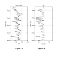
Figures 7A illustrates gas filled fractures identified from the crossplots ofFigure 6A and 6B plotted on a gamma ray log. -
Figure 7B illustrates gas filled fractures identified from the crossplots ofFigure 6A and 6B plotted on a water saturation log. -
Figure 8A illustrates a production log (gas and water production flux) at the reservoir depth, whereasFigure 8B illustrates water saturation values at the identified gas filled fracture locations. - While the present invention is susceptible to various modifications and alternative forms, specific exemplary embodiments thereof have been shown by way of example in the drawings and are herein described in detail. It should be understood, however, that the description herein of specific embodiments is not intended to limit the invention to the particular forms disclosed, but on the contrary, the intention is to cover all modifications, equivalents, and alternatives falling within the spirit and scope of the invention as defined by the appended claims.
- The present invention relates generally to methods and systems for fracture characterization of unconventional formations. More particularly, but not by way of limitation, embodiments of the present invention include methods and systems for fracture characterization of unconventional formations based on limited vertical well log data.
- Methods and systems are provided for deriving fracture parameters from common vertical well log data. Synthetic seismic fracture responses, or anisotropic synthetic seismograms, may be generated based on the derived fracture parameters. The synthetic seismic fracture responses or anisotropic synthetic seismograms may then be used to derive optimum seismic data acquisition geometry for fracture characterization. These methods of determining the seismic data acquisition geometry are advantageous over conventional methods in that these methods are more reliable and cheaper than many existing empirical methods, particularly as applied to fractured unconventional formations. Moreover, the methods disclosed herein allow the fracture parameters to be derived from limited but common well log data. Certain embodiments additionally contemplate determining the presence of gas filled fractures. These characterizations and evaluations of unconventional formations are useful for, among other things, determining optimal producing intervals and optimal drilling locations.
- Other optional variations and enhancements are described further below.
- Advantages of the methods disclosed herein include, but are not limited to, deriving P and S-wave anisotropy parameters from cross dipole sonic data, helping to generate synthetic fracture responses, and gas filled fracture identification for unconventional reservoirs with unidirectional fracture strikes. These methods can eliminate the use of costly image logs and core data. These methods ultimately translate to more efficient seismic imaging and more optimal hydrocarbon production. The methods disclosed herein are particularly advantageous in unconventional formations such as tight gas sand reservoirs or tight gas shale reservoirs where the formation is transversely isotropic with vertical and horizontal symmetry axis (VTI and HTI mediums respectively).
- Reference will now be made in detail to embodiments of the invention, one or more examples of which are illustrated in the accompanying drawings. Each example is provided by way of explanation of the invention, not as a limitation of the invention. It will be apparent to those skilled in the art that various modifications and variations can be made in the present invention without departing from the scope or spirit of the invention. For instance, features illustrated or described as part of one embodiment can be used on another embodiment to yield a still further embodiment. Thus, it is intended that the present invention cover such modifications and variations that come within the scope of the invention.
- Synthetic seismograms are the result of one of many forms of forward modeling to predict the seismic response of the Earth. A synthetic seismogram is a direct model of acoustic energy traveling through the layers of the Earth. A synthetic seismogram helps to provide well-tie, forward model building for inverse problem and anisotropic parameter estimation. The methods herein contemplate deriving Thomsen parameters from a vertical well log where only some limited, basic data is available (e.g. some sonic logs and a density log). Thomsen parameters can be used to generate anisotropic synthetic seismograms.
- A vertically fractured reservoir represents a transversely isotropic medium with horizontal axis of symmetry (HTI medium). Five anisotropic Thomsen parameters are required to completely define an HTI medium. Derivation of these five parameters from typical vertical well log data (containing P-wave velocity VP, fast (S1) and slow (S2) S-wave velocities VS1 and VS2, and density) is considered difficult and therefore several assumptions are made and empirical relations are used to derive these parameters.
- A method to derive Thomsen parameters from a vertical well log when only some basic data are available (i.e. vertical VP, VS1, VS2, and density) is presented here. This method may be applicable for HTI mediums. Further, it may be extended for VTI mediums when horizontal logs are available. The proposed methods do not require borehole image data or core analysis data. Additionally, the methods are easy to implement. The only assumption in this method is that the vertical P-wave and S-wave velocities are equal to the background isotropic P-wave and S-wave velocities. An example of deriving Thomsen parameters and other fracture parameters using a vertical well log data from Basin X in the Midwestern United States is presented the Examples section below. In this basin, the reservoir is tight sand and the natural fractures are vertical and have one dominant strike direction. Based on these observations, tight sand reservoir can be considered as an HTI medium. Implementing the proposed method, five rotated Thomsen parameters are derived from the limited well log data. Fracture density values in the reservoir level are also obtained as a byproduct of this method. Further investigation detects the presence of gas filled fractures.
- Vertical well log data set for this method contains VP, VS1, VS2, and density data from the fractured reservoir. The medium is considered HTI and the fractures contain either water or gas. With these assumptions all the Thomsen parameters are derived from the well log data along with the fracture density. Presence of gas filled fractures is also identified.
Fast and slow S-wave velocities (VS1 and VS2) in an HTI medium may be written as:
and
- Here ρ is the density of the background isotropic medium of the effective HTI medium and C¡j denote the stiffness matrix elements of the HTI medium. Now from the definition of the Thomsen parameter γ one can write:

- The same Thomsen parameter γ may also be written in terms of tangential fracture compliance ZT as:

where µ is the shear modulus of the background isotropic medium and can be derived from the vertical density and shear wave logs (equation 1), as for an HTI medium:
Once the value of ZT is obtained, then one can write:
where ZN is the normal fracture compliance and υ is the background isotropic medium's Poisson's ratio. The parameter υ can be derived using the vertical P and S-wave velocity logs. - Obtaining background P-wave velocity requires the knowledge of the presence of water filled fractures in the reservoir. At those locations vertical P-wave velocity of the HTI medium is the same as the background isotropic P-wave velocity, as ZN becomes zero at those locations. However, for practical purpose one can consider vertical P-wave velocity to be equal to the background P-wave velocity as normal fracture weakness (δ N ) values are relatively small (defined later).
- Once the ZN , ZT , values and background P-wave, S-wave velocities, and density are known, then the compliance matrix for the HTI medium can be written as:

- In equation 7, λ is the Lame's parameter and can be determined using background P-wave, S-wave velocities, and density. After evaluating equation 7, a simple matrix inversion can provide the stiffness matrix (C¡j) for the HTI medium. Therefore, it can be written:

- Once C¡j values are known, other Thomsen parameters ε and δ can be derived using the following equations:

and
- Therefore all the anisotropic Thomsen parameters are derived from the well log. Additionally, fracture density can be derived using the following equations:

and
- Here, e is the fracture density, g is the square of vertical VP, VS ratio, and δ N is the normal fracture weakness (introduced earlier).
-
Figure 1 shows a flowchart illustrating a method for fracture characterization in unconventional formations in accordance with one embodiment of the present invention. -
Method 100 commences withstep 110. Instep 110, a plurality of well logs are received or otherwise obtained. In this example, certain sonic logs as a function of depth are obtained, namely vertical P-wave velocities (VP), a vertical fast S-wave velocities (VS1), and a vertical slow S-wave velocities (VS2). In some cases, one may run well logs to obtain this data, or alternatively, this well log data may be simply obtained from another. - In
step 120, seismic fracture parameters are determined based on the well log data obtained instep 110. These fracture parameters determined may include an S-wave anisotropy (γ), a P-wave anisotropy (ε), and a move-out anisotropy (δ). - The S-wave anisotropy (γ) may be generated based on
equation 3 described above (or mathematical equivalent thereof) using the sonic values obtained instep 110. The P-wave anisotropy ε) may be obtained based on equations 7 and 9 (or mathematical equivalents thereof) as described above. The move-out anisotropy (δ) may be obtained based on equation 10 (or mathematical equivalent thereof). - In
step 130, synthetic seismic fracture responses or anisotropic synthetic seismograms may be generated based on the seismic fracture parameters obtained instep 120. Examples of methods for generating seismic fracture parameters include, for example, accurate finite difference methods, reflectivity methods, ray tracing methods, approximate convolution method, or any combination thereof. - In
step 140, a seismic data acquisition geometry may be derived from the synthetic seismic fracture responses determined instep 130. An optimum offset azimuth distribution may be calculated from the anisotropic synthetic seismogram for which fracture responses can be prominent and easy to identify. The seismic data acquisition geometry may optionally be used to optimally physically arrange a plurality of seismic receivers and at least one seismic source based on the seismic data acquisition geometry for real data acquisition. - In
optional step 150, gas filled fractures may be identified as a function of depth. To identify gas filled fractures as a function of wellbore depth (i), one may determine a ratio of a normal fracture compliance (ZN,i) to a tangential fracture compliance (ZT,1) based on the vertical P-wave velocity VP,i, the vertical fast S-wave velocity (VS1,i), the vertical slow S-wave velocity (VS2,i) and the density (ρi). As described in more detail above, the ratio ZN,i/ZT,i may be determined by the relationship 1 - νi/2, wherein νi is Poisson's ratio of the formation at each wellbore depth i, wherein vi is derived from the vertical P-wave velocity VP,i, the vertical fast S-wave velocity (VS1,i), the vertical slow S-wave velocity(VS2,i) and the density (ρi) as Vi=λi/2(λi+λi). µi can be derived using Vsli and ρi (usingEqn 1 and 5) and λi may be derived from P-wave velocity log as VPi 2= (λi+2µi)/ρi. - A gas filled fracture presence indicator may be determined based on the determinations in
step 150, namely the ratio ZN,i/ZT,I and the porosity (ϕi). Gas filled fractures are indicated at a well depth i where the ratio ZN,1/ZT,i is above a first threshold and the porosity (ϕi) is below a second threshold. Suitable values of the first threshold and second threshold that result in reliable predictions of gas filled fractures include, but are not limited to, a first threshold of about 0.85 and a second threshold below the fracture porosity of the formation at each wellbore depth. Other values that may be used for the first threshold include any value between about 0.85 to about 1 and any value between about 0.95 to about 1. - In
optional step 160, an operator may produce hydrocarbons from intervals of the wellbore having gas-filled fractures as identified instep 150. - In
step 170, any of the above determined results may be outputted to a user, including, but not limited to, the seismic fracture parameters, the synthetic seismic responses, the seismic data acquisition geometry, and the gas-filled presence indicator. - The methods described herein are particularly applicable to unconventional reservoirs and especially horizontally transverse isotropic (HTI) medium. In certain embodiments, the unconventional reservoir is a tight gas sand reservoir or a tight gas shale reservoir. Unlike many of the conventional methods, the methods described herein may be used where no image log is used to determine the plurality of fracture parameters.
- It is recognized that any of the elements and features of each of the devices described herein are capable of use with any of the other devices described herein with no limitation. Furthermore, it is recognized that the steps of the methods herein may be performed in any order except unless explicitly stated otherwise or inherently required otherwise by the particular method.
- To facilitate a better understanding of the present invention, the following examples of certain embodiments are given. In no way should the following examples be read to limit, or define, the scope of the invention.
- An example of deriving Thomsen parameters and other fracture parameters using a vertical well log data from basin X in the Midwestern United States is presented here. In this basin the reservoir is tight sand and the natural fractures are vertical and have one dominant strike direction. Based on these observations, tight sand reservoir can be considered as an HTI medium. Implementing the proposed method, five rotated Thomsen parameters are derived from the limited well log data. Fracture density values in the reservoir level are also obtained as a byproduct of this method. Further investigation detects the presence of gas filled fractures. A plot of gas filled fractures is presented on the water saturation log. Presence of gas filled fractures also correlate nicely with the gamma ray log (to show the presence of the fractures in sand) and production data.
- Basin X is located in the Midwestern United States and is one of the largest gas fields in the United States. In this area, a west to northwest trending regional maximum stress exists that helped to develop aligned vertical fractures at the reservoir level (Lorenz and Finley, 1991). Study area is located in the north side of the basin X. The reservoir is composed of tight sand with porosity of 1%-15%. A separate study (Lewallen et al. 2008) from this area shows presence of open vertical fractures with constant strike directions at the reservoir level. Based on this study, the reservoir here can be assumed an HTI medium with one dominant fracture direction.
- One vertical well data from this area is used in this method. Well log data contain VP, VS1, VS2, density, porosity (ϕ), and water saturation (SW) data.
Figure 2 shows the vertical VP, VS1, VS2, and density data used in this study. Then, using the methods described herein and equations 2 - 10, anisotropic Thomsen parameters γ, δ, and ε are determined, the results of which are shown inFigure 3 .Figure 4A shows a crossplot of Thomsen parameter γ and ε derived from the equations described herein (black circles), whereasFigure 4B shows a crossplot of ε and δ derived from the equations described herein (black circles). For comparison purposes, the gray lines on the both crossplots are shown between Thomsen parameters based on an empirical relation by Wang (2002). A little deviation is apparent inFigures 4A and 4B between empirical relationship and the theoretical results from the methods herein. - A fracture density log may be generated using equations 11 and 12. The log is shown in
Figure 5 . As shown inFigure 5 , the density values are small and therefore good for the assumptions of the methods described herein. Subsequently, the gas filled fractures may be identified from the available data. For that identification, a crossplot of ZN/ZT and effective porosity may be generated as shown inFigure 6 . For gas filled fractures, the value of ZN/ZT is almost 1. Since fracture porosity in this field is very low (6%), using these constraints, gas filled fractures may be identified from the log as shown by plus sign in the lower right quadrant ofFigure 6 (that is, those points above a ZN/ZT value of 0.9 and a porosity below 6%. These gas filled fracture points may be plotted on the gamma ray log and water saturation log (diamond points inFigure 7A ). It is evident that the gas filled fractures are present in the sand only (Figure 7A ), and they are at the positions where water saturation is low (Figure 7B ). There are very few deviations from this observation inFigures 7A and 7B . Except for a few points, identified gas filled fractures match the water saturation log quite well. To understand this mismatch, the results may be compared with the production data. Infigure 8A , the production log (gas and water production flux) at the reservoir depth is plotted.Figure 8B shows the water saturation values at the location where gas filled fractures have been identified. InFigure 8B , areas of high water saturation values are marked with black boxes in locations where gas filled fractures. Therefore, within these boxes, the methods predict the presence of gas filled fractures, whereas the saturation log is predicting presence of water. When these areas are compared with the production data, one can see that the production data supports presence of gas in this area. One explanation to this observation could be presence of gas filled fractures in a water saturated matrix. Nonetheless, good correlation between production data and derived gas filled fractures indicates the satisfactory identification of gas filled fractures using the methods described herein. - Therefore, the present invention is well adapted to attain the ends and advantages mentioned as well as those that are inherent therein. The particular embodiments disclosed above are illustrative only, as the present invention may be modified and practiced in different but equivalent manners apparent to those skilled in the art having the benefit of the teachings herein. Furthermore, no limitations are intended to the details of construction or design herein shown, other than as described in the claims below. It is therefore evident that the particular illustrative embodiments disclosed above may be altered or modified and all such variations and equivalents are considered within the scope and spirit of the present invention. Also, the terms in the claims have their plain, ordinary meaning unless otherwise explicitly and clearly defined by the patentee.
Claims (14)
- A method for fracture characterization in unconventional formations comprising the steps of:receiving a plurality of vertical P-wave velocities (VP) at the plurality of wellbore depths;receiving a plurality of vertical fast S-wave velocities (VS1) at the plurality of wellbore depths;receiving a plurality of vertical slow S-wave velocities (VS2) at the plurality of wellbore depths;receiving a plurality of densities (p) at the plurality of wellbore depths;determining a plurality of seismic fracture parameters at the plurality ofwellbore depths based on said velocities (VP VS1 VS2) and densities (ρ), the seismic fracture parameters comprising an S-wave anisotropy (γ), a P-wave anisotropy (ε), and a move-out anisotropy (δ);wherein C is a stiffness matrix, and wherein Cij is an element from row i and column j of the stiffness matrix;wherein the S-wave anisotropy (γi) is determined at each well bore depth (i) according to the relationship
 wherein the P-wave anisotropy (εi) is determined at each well bore depth (i) according to the relationship
 wherein the move-out anisotropy (δi) is determined at each well bore depth (i) according to the relationship
 generating synthetic seismic fracture responses based on the seismic fracture parameters; andderiving a seismic data acquisition geometry based on the synthetic seismic fracture responses.
 - A method for fracture characterization in unconventional formations comprising the steps of:logging a well at a plurality of wellbore depths to obtain a plurality of well logs, the plurality of well logs comprising a vertical P-wave velocity log, a vertical fast S-wave velocity log, a vertical slow S-wave velocity log, and a density log;wherein the vertical P-wave velocity log comprises a plurality of vertical P-wave velocities (VP) at the plurality of wellbore depths;wherein the vertical fast S-wave velocity log comprises a plurality of vertical fast S-wave velocities (VS1) at the plurality of wellbore depths;wherein the vertical slow S-wave velocity log comprises a plurality of vertical slow S-wave velocities (VS2) at the plurality of wellbore depths;wherein the density log comprises a plurality of densities (p) at the plurality of wellbore depths;determining a plurality of seismic fracture parameters at the plurality of wellbore depths based on the plurality of well logs, the seismic fracture parameters comprising an S-wave anisotropy (γ), a P-wave anisotropy (ε), and a move-out anisotropy (δ);wherein C is a stiffness matrix, and wherein C¡j is an element from row i and column j of the stiffness matrix;wherein the S-wave anisotropy (γi) is determined at each well bore depth (i) according to the relationship
 wherein the P-wave anisotropy (εi) is determined at each well bore depth (i) according to the relationship
 wherein the move-out anisotropy (δi) is determined at each well bore depth (i) according to the relationship
 generating synthetic seismic fracture responses based on the seismic fracture parameters; andderiving a seismic data acquisition geometry based on the synthetic seismic fracture responses.
 - The method of claim 1 or claim 2 further comprising the step of physically arranging a plurality of seismic receivers and at least one seismic source based on the seismic data acquisition geometry.
- The method of claim 1 or claim 2 further comprising the steps of:(a) determining the presence of gas filled fractures at each depth; and(b) producing from the intervals with gas filled fractures.
- The method of claim 4 wherein step (a) further comprises determining, at each wellbore depth (i), the ratio of a normal fracture compliance (ZN,i) to a tangential fracture compliance (ZT,1) based on the vertical P-wave velocity VP,i, the vertical fast S-wave velocity (VS1,i), the vertical slow S-wave velocity (VS2,i) and the density (ρi).
wherein the ratio ZN,1/ZT,1 is characterized by the relationship 1 - νi/2, wherein νi is Poisson's ratio of the formation at each wellbore depth i and wherein vi is derived from the vertical P-wave velocity VP,1, the vertical fast S-wave velocity (VS1,i), the vertical slow S-wave velocity (VS2,i) and the density (ρi); and
outputting to a user a gas filled fracture presence indicator for both (i) any ratio ZN,1/ZT,1 above a first threshold and (ii) for any porosity (ϕi) below a second threshold. - The method of claim 5 wherein the first threshold is between about 0.85 and about 1.
- The method of claim 6 wherein the first threshold is between about 0.95 and about 1.
- The method of claim 4 wherein the second threshold is below the fracture porosity of the formation at each wellbore depth.
- The method of claim 1 or claim 2 wherein the unconventional reservoir is a horizontally transverse isotropic (HTI) medium.
- The method of claim 1 or claim 2 wherein the unconventional reservoir is a tight gas sand reservoir or a tight gas sand reservoir
- The method of claim 5 wherein the step of outputting further comprises displaying the gas filled fracture presence indicator on a display.
- The method of claim 1 or claim 2 wherein no image log is used to determine the plurality of fracture parameters.
- The method of claim 8:
wherein the unconventional reservoir is a horizontally transverse isotropic (HTI) medium;
wherein the unconventional reservoir is a tight gas sand reservoir or a tight gas sand reservoir;
wherein the step of outputting further comprises displaying the gas filled fracture presence indicator on a display; and
wherein no image log is used to determine the plurality of fracture parameters. - The method of claim 1 further comprising the step of logging a well at the plurality of wellbore depths to obtain a plurality of well logs, the plurality of well logs comprising the vertical P-wave velocities (VP), the vertical fast S-wave velocities (VS1), the vertical slow S-wave velocities (VS2), and the densities (p).
Applications Claiming Priority (1)
| Application Number | Priority Date | Filing Date | Title |
|---|---|---|---|
| US201161468110P | 2011-03-28 | 2011-03-28 |
Publications (2)
| Publication Number | Publication Date |
|---|---|
| EP2506039A2 true EP2506039A2 (en) | 2012-10-03 |
| EP2506039A3 EP2506039A3 (en) | 2013-08-14 |
Family
ID=45999600
Family Applications (1)
| Application Number | Title | Priority Date | Filing Date |
|---|---|---|---|
| EP12160883.0A Withdrawn EP2506039A3 (en) | 2011-03-28 | 2012-03-22 | Methods for Seismic Fracture Parameter Estimation and Gas Filled Fracture Identification From Vertical Well Log Data |
Country Status (2)
| Country | Link |
|---|---|
| US (1) | US8982666B2 (en) |
| EP (1) | EP2506039A3 (en) |
Cited By (8)
| Publication number | Priority date | Publication date | Assignee | Title |
|---|---|---|---|---|
| CN104297784A (en) * | 2014-08-12 | 2015-01-21 | 中国石油化工股份有限公司 | Primary wave azimuthal anisotropy based fracture predicting method |
| CN104516015A (en) * | 2013-09-27 | 2015-04-15 | 中国石油天然气集团公司 | Method for determining longitudinal wave speed and transverse wave speed of coalbed gas |
| CN106054279A (en) * | 2016-08-17 | 2016-10-26 | 西安科技大学 | Coal rock brittleness index determination method |
| KR101902779B1 (en) | 2016-07-28 | 2018-10-02 | 한국지질자원연구원 | Method for estimating velocity of S wave from other logging data |
| CN109425888A (en) * | 2017-08-21 | 2019-03-05 | 中国科学院遥感与数字地球研究所 | A kind of methane concentration Pick-up precursor information method for seismic monitoring |
| CN112731556A (en) * | 2019-10-28 | 2021-04-30 | 中国石油化工股份有限公司 | Crack development region prediction method and computer storage medium for predicting crack development region |
| CN114609669A (en) * | 2022-05-10 | 2022-06-10 | 青岛油金能源科技有限公司 | HTI type fracture reservoir parameter prediction method and system based on azimuth elastic impedance |
| CN117874903A (en) * | 2024-03-13 | 2024-04-12 | 江苏省建筑工程质量检测中心有限公司 | Engineering quality assessment diagnosis method and system integrating Internet of things and artificial intelligence |
Families Citing this family (19)
| Publication number | Priority date | Publication date | Assignee | Title |
|---|---|---|---|---|
| CN102967883B (en) * | 2012-11-20 | 2016-02-10 | 中国石油集团川庆钻探工程有限公司地球物理勘探公司 | By the method for shale gas prestack elastic parameter inversion prediction rock fragility probability |
| US10822922B2 (en) * | 2015-01-19 | 2020-11-03 | International Business Machines Corporation | Resource identification using historic well data |
| US9958572B2 (en) * | 2015-03-31 | 2018-05-01 | Halliburton Energy Services, Inc. | Synthetic test beds for fracturing optimization and methods of manufacture and use thereof |
| WO2017023282A1 (en) | 2015-07-31 | 2017-02-09 | Halliburton Energy Services Inc. | Logging with joint ultrasound and x-ray technologies |
| CN106569266B (en) * | 2015-10-12 | 2018-11-20 | 中国石油化工股份有限公司 | Shale gas reservoir brittle mineral content prediction method |
| CN107524437B (en) * | 2016-06-21 | 2020-07-28 | 中国石油化工股份有限公司 | Method and system for determining opening of reservoir fracture |
| CN107060741B (en) * | 2016-12-05 | 2019-12-24 | 中国科学院声学研究所 | Phase-control double-cross dipole logging method |
| CN108573076B (en) * | 2017-03-09 | 2021-08-31 | 中国石油化工股份有限公司 | Prediction method for shale gas fracturing construction accident |
| CN106907140B (en) * | 2017-04-28 | 2020-11-13 | 新疆大学 | Method for determining high-yield stratum level of hydrodynamic enclosed coal bed gas based on logging information |
| CN111562630B (en) * | 2019-02-13 | 2023-06-20 | 中国石油化工集团有限公司 | Reservoir parameter logging evaluation method based on grid division |
| CN112083485B (en) * | 2019-06-14 | 2024-03-01 | 中国石油天然气集团有限公司 | Oil gas distribution detection method and device |
| CN112147698B (en) * | 2019-06-28 | 2023-04-07 | 中国石油化工股份有限公司 | Crack development zone identification and feature determination method and system |
| CN110378004B (en) * | 2019-07-11 | 2021-05-07 | 中国石油大学(北京) | Correction method for interpreting fracturing fracture parameter result by microseism |
| CN112799135A (en) * | 2019-11-14 | 2021-05-14 | 中国石油天然气集团有限公司 | Fractured reservoir prediction method and device, computer equipment and readable storage medium |
| US11681065B2 (en) * | 2020-02-17 | 2023-06-20 | Halliburton Energy Services, Inc. | Depth-continuous estimation of the elastic tensor using single depth borehole sonic measurements |
| CN113325468B (en) * | 2020-02-28 | 2023-06-30 | 中国石油天然气集团有限公司 | Reservoir fracture-cavity distribution range prediction method and device |
| CN111880234B (en) * | 2020-06-24 | 2022-09-30 | 西南石油大学 | Fine identification method for tight reservoir fractures based on conventional well logging |
| CN114135264B (en) * | 2020-08-14 | 2024-04-02 | 中国石油化工股份有限公司 | Method, device and storage medium for determining development degree of microcracks of tight sandstone |
| CN112379437B (en) * | 2020-11-02 | 2024-03-26 | 中国石油天然气集团有限公司 | Shale reservoir anisotropy parameter solving method and device |
Family Cites Families (17)
| Publication number | Priority date | Publication date | Assignee | Title |
|---|---|---|---|---|
| GB9206681D0 (en) * | 1992-03-27 | 1992-05-13 | Geco As | A method of making a synthetic seismogram |
| US6930616B2 (en) * | 2000-11-13 | 2005-08-16 | Baker Hughes Incorporated | Method and apparatus for LWD shear velocity measurement |
| FR2821677B1 (en) * | 2001-03-05 | 2004-04-30 | Geophysique Cie Gle | IMPROVEMENTS TO TOMOGRAPHIC INVERSION PROCESSES OF POINTED EVENTS ON MIGREE SEISMIC DATA |
| US6714480B2 (en) * | 2002-03-06 | 2004-03-30 | Schlumberger Technology Corporation | Determination of anisotropic moduli of earth formations |
| US6904368B2 (en) * | 2002-11-12 | 2005-06-07 | Landmark Graphics Corporation | Seismic analysis using post-imaging seismic anisotropy corrections |
| WO2004095077A1 (en) * | 2003-04-23 | 2004-11-04 | Commonwealth Scientific And Industrial Research Organisation | Method for predicting pore pressure |
| US6901333B2 (en) * | 2003-10-27 | 2005-05-31 | Fugro N.V. | Method and device for the generation and application of anisotropic elastic parameters |
| US7626886B2 (en) * | 2006-06-06 | 2009-12-01 | Baker Hughes Incorporated | P-wave anisotropy determination using borehole measurements |
| US7751980B2 (en) * | 2006-12-22 | 2010-07-06 | Schlumberger Technology Corporation | Method and apparatus for evaluating elastic mechanical properties of a transversely isotropic formation |
| US7924652B2 (en) * | 2007-06-01 | 2011-04-12 | Baker Hughes Incorporated | Method for determining seismic anisotropy |
| WO2009126375A1 (en) * | 2008-04-09 | 2009-10-15 | Exxonmobil Upstream Research Company | Method for generating anisotropic resistivity volumes from seismic and log data using a rock physics model |
| US8750074B2 (en) * | 2008-11-25 | 2014-06-10 | Baker Hughes Incorporated | Anisotropic parameter determination |
| US8407007B2 (en) * | 2008-12-02 | 2013-03-26 | Baker Hughes Incorporated | Anisotropic depth velocity model estimation above the receiver array in walkaway or 3D VSP data |
| CN102870009A (en) * | 2010-03-12 | 2013-01-09 | 地球物理维里达斯集团(美国)有限公司 | Methods and systems for performing azimuthal simultaneous elatic inversion |
| US9513395B2 (en) * | 2010-08-30 | 2016-12-06 | Microseismic, Inc. | Method for detection of subsurface seismic events in vertically transversely isotropic media |
| US8914270B2 (en) * | 2011-02-22 | 2014-12-16 | Cggveritas Services Sa | Preserved-traveltime smoothing method and device |
| US20140336940A1 (en) * | 2013-05-10 | 2014-11-13 | Schlumberger Technology Corporation | Estimation of q-factor in time domain |
-
2012
- 2012-03-22 EP EP12160883.0A patent/EP2506039A3/en not_active Withdrawn
- 2012-03-26 US US13/430,190 patent/US8982666B2/en not_active Expired - Fee Related
Non-Patent Citations (1)
| Title |
|---|
| None |
Cited By (11)
| Publication number | Priority date | Publication date | Assignee | Title |
|---|---|---|---|---|
| CN104516015A (en) * | 2013-09-27 | 2015-04-15 | 中国石油天然气集团公司 | Method for determining longitudinal wave speed and transverse wave speed of coalbed gas |
| CN104516015B (en) * | 2013-09-27 | 2017-03-15 | 中国石油天然气集团公司 | A kind of method for determining coal bed gas compressional wave and shear wave velocity |
| CN104297784A (en) * | 2014-08-12 | 2015-01-21 | 中国石油化工股份有限公司 | Primary wave azimuthal anisotropy based fracture predicting method |
| KR101902779B1 (en) | 2016-07-28 | 2018-10-02 | 한국지질자원연구원 | Method for estimating velocity of S wave from other logging data |
| CN106054279A (en) * | 2016-08-17 | 2016-10-26 | 西安科技大学 | Coal rock brittleness index determination method |
| CN106054279B (en) * | 2016-08-17 | 2017-07-04 | 西安科技大学 | A kind of determination method of coal petrography brittleness index |
| CN109425888A (en) * | 2017-08-21 | 2019-03-05 | 中国科学院遥感与数字地球研究所 | A kind of methane concentration Pick-up precursor information method for seismic monitoring |
| CN109425888B (en) * | 2017-08-21 | 2021-01-19 | 中国科学院遥感与数字地球研究所 | Methane concentration precursor information extraction method for earthquake monitoring |
| CN112731556A (en) * | 2019-10-28 | 2021-04-30 | 中国石油化工股份有限公司 | Crack development region prediction method and computer storage medium for predicting crack development region |
| CN114609669A (en) * | 2022-05-10 | 2022-06-10 | 青岛油金能源科技有限公司 | HTI type fracture reservoir parameter prediction method and system based on azimuth elastic impedance |
| CN117874903A (en) * | 2024-03-13 | 2024-04-12 | 江苏省建筑工程质量检测中心有限公司 | Engineering quality assessment diagnosis method and system integrating Internet of things and artificial intelligence |
Also Published As
| Publication number | Publication date |
|---|---|
| US20120250459A1 (en) | 2012-10-04 |
| EP2506039A3 (en) | 2013-08-14 |
| US8982666B2 (en) | 2015-03-17 |
Similar Documents
| Publication | Publication Date | Title |
|---|---|---|
| US8982666B2 (en) | Methods for seismic fracture parameter estimation and gas filled fracture identification from vertical well log data | |
| Maxwell | Microseismic imaging of hydraulic fracturing: Improved engineering of unconventional shale reservoirs | |
| Collett et al. | Downhole well log and core montages from the Mount Elbert gas hydrate stratigraphic test well, Alaska North Slope | |
| Lee et al. | In-situ gas hydrate hydrate saturation estimated from various well logs at the Mount Elbert Gas Hydrate Stratigraphic Test Well, Alaska North Slope | |
| Franco et al. | Sonic investigation in and around the borehole | |
| US8681582B2 (en) | Method for sonic indication of formation porosity and lithology | |
| Mandal et al. | Geomechanical appraisal and prospectivity analysis of the Goldwyer shale accounting for stress variation and formation anisotropy | |
| CN101315428B (en) | High resolution prospecting method of large-ventage clastic rock deposition stratum based on horizontal wave velocity | |
| CN105370270B (en) | The method that shale gas reservoir gas-bearing saturation degree is determined by the dipole sonic P-wave And S time difference | |
| Cheng et al. | Acoustic waveform logging-advances in theory and application | |
| Gupta et al. | PP and SS wave interpretation of a carbonate formation: A case study from the Arbuckle interval in Wellington field, Kansas | |
| Hatchell et al. | Integrating 4D seismic, geomechanics and reservoir simulation in the Valhall oil field | |
| Wojtowicz et al. | Reconstructing the mechanical parameters of a transversely-isotropic rock based on log and incomplete core data integration | |
| Mohammed et al. | Latest generation logging while drilling sonic tool: Multipole acoustics measurements in horizontal wells from offshore west South Africa | |
| Tran | Formation evaluation of an unconventional shale reservoir: Application to the North Slope Alaska | |
| Leary et al. | Crosswell seismic applications to highly heterogeneous tight gas reservoirs | |
| Onajite | Seismic petrophysics and petrophysical well curves analysis for quantitative seismic interpretation | |
| Marouby et al. | Assessment of in-situ elastic properties of hydrocarbon-bearing shale with the joint quantitative interpretation of sonic, nuclear, and resistivity logs | |
| Quirein et al. | Geomechanical Workflow and Sensitivity Study for Calibrating and Predicting Elastic Moduli and Minimum Horizontal Stress from Well Logs in an Anisotropic Formation | |
| Kamel et al. | Estimating seismic impedance and elastic parameters in hydrocarbon-bearing reservoirs from acoustic logs | |
| Wang et al. | Interpretation of sonic waveforms acquired in high-angle and horizontal wells | |
| Schuelke | Overview of seismic attribute analysis in shale plays | |
| Nanda | Borehole seismic techniques | |
| Sirju et al. | Joint inversion of array induction and sonic data for radial variations of porosity and saturation in complex mineralogy | |
| Grant et al. | The application of VSP in the Pilbara |
Legal Events
| Date | Code | Title | Description |
|---|---|---|---|
| PUAI | Public reference made under article 153(3) epc to a published international application that has entered the european phase |
Free format text: ORIGINAL CODE: 0009012 |
|
| 17P | Request for examination filed |
Effective date: 20120322 |
|
| AK | Designated contracting states |
Kind code of ref document: A2 Designated state(s): AL AT BE BG CH CY CZ DE DK EE ES FI FR GB GR HR HU IE IS IT LI LT LU LV MC MK MT NL NO PL PT RO RS SE SI SK SM TR |
|
| AX | Request for extension of the european patent |
Extension state: BA ME |
|
| PUAL | Search report despatched |
Free format text: ORIGINAL CODE: 0009013 |
|
| RIC1 | Information provided on ipc code assigned before grant |
Ipc: G01V 1/44 20060101AFI20130704BHEP |
|
| AK | Designated contracting states |
Kind code of ref document: A3 Designated state(s): AL AT BE BG CH CY CZ DE DK EE ES FI FR GB GR HR HU IE IS IT LI LT LU LV MC MK MT NL NO PL PT RO RS SE SI SK SM TR |
|
| AX | Request for extension of the european patent |
Extension state: BA ME |
|
| 17Q | First examination report despatched |
Effective date: 20130730 |
|
| RBV | Designated contracting states (corrected) |
Designated state(s): AL AT BE BG CH CY CZ DE DK EE ES FI FR GB GR HR HU IE IS IT LI LT LU LV MC MK MT NL NO PL PT RO RS SE SI SK SM TR |
|
| STAA | Information on the status of an ep patent application or granted ep patent |
Free format text: STATUS: THE APPLICATION IS DEEMED TO BE WITHDRAWN |
|
| 18D | Application deemed to be withdrawn |
Effective date: 20171003 |