EP2505926A1 - Oven, especially domestic oven - Google Patents
Oven, especially domestic oven Download PDFInfo
- Publication number
- EP2505926A1 EP2505926A1 EP11002629A EP11002629A EP2505926A1 EP 2505926 A1 EP2505926 A1 EP 2505926A1 EP 11002629 A EP11002629 A EP 11002629A EP 11002629 A EP11002629 A EP 11002629A EP 2505926 A1 EP2505926 A1 EP 2505926A1
- Authority
- EP
- European Patent Office
- Prior art keywords
- drawer
- oven according
- rail
- rails
- oven
- Prior art date
- Legal status (The legal status is an assumption and is not a legal conclusion. Google has not performed a legal analysis and makes no representation as to the accuracy of the status listed.)
- Withdrawn
Links
- 239000002184 metal Substances 0.000 claims description 5
- 230000007704 transition Effects 0.000 claims description 4
- 230000000149 penetrating effect Effects 0.000 claims description 2
- 238000004519 manufacturing process Methods 0.000 description 2
- 239000007795 chemical reaction product Substances 0.000 description 1
- 238000010411 cooking Methods 0.000 description 1
- 239000000463 material Substances 0.000 description 1
- 230000002265 prevention Effects 0.000 description 1
Images




Classifications
-
- F—MECHANICAL ENGINEERING; LIGHTING; HEATING; WEAPONS; BLASTING
- F24—HEATING; RANGES; VENTILATING
- F24C—DOMESTIC STOVES OR RANGES ; DETAILS OF DOMESTIC STOVES OR RANGES, OF GENERAL APPLICATION
- F24C15/00—Details
- F24C15/16—Shelves, racks or trays inside ovens; Supports therefor
Definitions
- the invention relates to an oven, especially to a domestic oven, comprising a cavity, wherein at least one drawer is arranged in the cavity, wherein the drawer can be moved relatively to the cavity in a horizontal slide direction, wherein at least two longitudinal extending rails are arranged parallel to another in the cavity and being oriented into the slide direction and wherein the drawer is arranged slidable on the rails.
- a domestic oven according to this kind is know from DE 100 54 954 B4 .
- a drawer which can be moved in a horizontal direction into and out of the cavity of the oven is arranged on guiding rails.
- the arrangement can be established as a sliding bearing, while the use of linear roller bearings is preferred.
- a telescopic solution is proposed.
- Another similar design is disclosed in DE 198 47 727 C2 , i. e. also here a telescopic arrangement is employed, wherein a sliding bearing is used for movement of the drawer.
- the solution of this object is characterized in that the drawer has at least two sliding surfaces at its bottom side, which sliding surfaces are arranged for sliding on a top surface of the rails, wherein the drawer has at least two holding elements at its bottom side which holding elements are arranged for sliding on a bottom surface of the rails.
- the rails have a cross section consisting of two lower flat bands extending in a horizontal plane and an upper flat band extending in a horizontal plane.
- the rails can have two flat connection bands extending in a vertical plane and connecting the upper flat band with the two lower flat bands.
- the bottom surface of the rail can be arranged at the bottom side of the upper flat band.
- the top surface of the rail can be arranged at the upper side of one of the lower flat bands.
- the sliding surfaces of the drawer can be formed by at least two rib elements which are arranged at the bottom side of the drawer.
- the holding element can be formed by a L-shaped or T-shaped or Z-shaped rib part which is fixed at the bottom side of the drawer.
- the holding element can be arranged at one end of the drawer seen in slide direction.
- the length of the holding element in slide direction is preferably below 15 % of the length of the drawer in slide direction.
- the rail can have a longitudinal extending slot, wherein a vertically extending part of the holding element (a rib part) of the drawer is penetrating the slot.
- the rail can have a cut out adjacent to one end of the slot with a bigger size than the size of the slot for receiving the holding element.
- the rail can have a chamfered transition zone between the cut out and the slot.
- the rail can have a guiding element at one of its axial ends forming a guiding surface for the rib element.
- the rail can be made of a sheet metal part, wherein the guiding element is produced by deformation of a section of the sheet metal part.
- the rail is preferably symmetrically to a plane being arranged vertically and extending in the slide direction.
- the concept according to the invention thus proposes a cheaper drawer sliding system without wheels and shafts. It makes preferably use of symmetrically formed rails, which can be used on the left and right side under the drawer and therefore requires only one set of tools for manufacturing.
- the invention supplies a relatively cheap guiding solution for low end products, which avoids wheels and shafts but which also provides a sufficient comfort in handling of the drawer.
- the two rails are fastened to the plinth of the oven.
- the rails have the function to guide the drawer in a proper way on the full pull out distance of the drawer.
- the rail is designed as a fully symmetrical part in order to use it as left and right guidance for the drawer.
- the drawer will be assembled to the rails.
- This cut out is defined in width and length to be able to receive the holding element (e. g. with a L-rib) of the drawer at the left and right rail at the same time without creating problems (for example three tries for assembly).
- the drawer After receiving the holding element (e. g. the L-rib) by the cut out the drawer can be pushed inside the oven in slide direction.
- the holding element e. g. the L-rib
- the holding element e. g. the L-rib
- This slot ensures the guidance of the drawer on the full pull out distance.
- a rib element ensures a proper sliding over the whole distance and keeps the drawer also in horizontal position (slide direction).
- the rib element is guided by a guiding element (bridge element) at the rail. Both rib elements together (the rib part of the holding element and the rib element) are guarantying a good guiding system even if the drawer is pulled out to the limit.
- the tool costs for producing the rails are kept at a minimum due to the symmetric design of the rails.
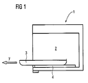
- a domestic oven 1 is shown schematically which has a cooking cavity 2.
- a drawer 3 on which food can be placed is arranged on two rails 4.
- the drawer 3 can be pulled out of the cavity in a slide direction y.
- Fig. 2 shows a plinth 20 which is arranged in the bottom region of the cavity 2.
- Two rails 4 are arranged in the side region of the plinth 20; the drawer 3 can slide on the rails 4 to be moved forth and back in the slide direction y.
- each rail 4 is symmetrically to a plane which is arranged vertically and contains the slide direction y.
- Fig. 5 In the bottom side 6 of the drawer 3 - see Fig. 5 - two sliding surfaces 5 are arranged which are running parallel to another in the side regions of the drawer 3.
- the sliding surfaces 5 are formed by rib elements 15 which are located in the bottom of the drawer 3.
- Holding elements 8 are arranged at one end of the rib elements 15.
- the holding elements 8 have a cross section - seen in slide direction y - as schematically shown for three examples in Fig. 8a, 8b and 8c , see below.
- Each rail 4 is formed from a sheet metal strip by deforming. It has two lower flat bands 10 and 11 extending in slide direction y as well as an upper flat band 12.
- the upper flat band 12 is connected with the lower flat bands 10 and 11 by flat connection bands 13 and 14 (see Fig. 7 ).
- a top surface 7 is formed on one of the lower flat bands which is contacted by the sliding surface 5 of the rib elements 15 of the drawer 3.
- a bottom surface 9 is formed by the bottom side of the upper flat band 12 (see Fig. 7 ).
- the upper flat band 12 has a slot 16 which extends along most of the extension of the rail 4.
- the holding element 8 extends along a certain extension vertically downward from the drawer 3.
- the holding element 8 penetrates the slot 16 downwards.
- the bottom surface 9 is established.
- a part of the holding element 8 finds here a sliding counter face due to the circumstance that the holding element has e. g. a T-shaped form (see Fig. 8a ) or a L-shaped form (see Fig. 8b ) or a Z-shaped form (see Fig. 8c ).
- a chamfered transition zone 18 makes sure that the holding elements 8 are easily fed into the slot 16.
- a bridge-like guiding element 19 is formed at one end of the rail 4. This element is formed from the material of the rail 4 by deforming.
Landscapes
- Engineering & Computer Science (AREA)
- Chemical & Material Sciences (AREA)
- Combustion & Propulsion (AREA)
- Mechanical Engineering (AREA)
- General Engineering & Computer Science (AREA)
- Drawers Of Furniture (AREA)
Abstract
The invention relates to an oven (1), especially to a domestic oven, comprising a cavity (2), wherein at least one drawer (3) is arranged in the cavity (2), wherein the drawer (3) can be moved relatively to the cavity (2) in a horizontal slide direction (y), wherein at least two longitudinal extending rails (4) are arranged parallel to another in the cavity (2) and being oriented into the slide direction (y) and wherein the drawer (3) is arranged slidable on the rails (4). To obtain an economical solution for the slidable arrangement of the drawer the invention is characterized in that the drawer (3) has at least two sliding surfaces (5) at its bottom side (6), which sliding surfaces (5) are arranged for sliding on a top surface (7) of the rails (4), wherein the drawer (3) has at least two holding elements (8) at its bottom side (6) which holding elements (8) are arranged for sliding on a bottom surface (9) of the rails (4).
Description
- The invention relates to an oven, especially to a domestic oven, comprising a cavity, wherein at least one drawer is arranged in the cavity, wherein the drawer can be moved relatively to the cavity in a horizontal slide direction, wherein at least two longitudinal extending rails are arranged parallel to another in the cavity and being oriented into the slide direction and wherein the drawer is arranged slidable on the rails.
- A domestic oven according to this kind is know from
DE 100 54 954 B4 . Here, a drawer which can be moved in a horizontal direction into and out of the cavity of the oven is arranged on guiding rails. The arrangement can be established as a sliding bearing, while the use of linear roller bearings is preferred. For obtaining a sufficient travel of the drawer in the horizontal direction a telescopic solution is proposed. Another similar design is disclosed inDE 198 47 727 C2 , i. e. also here a telescopic arrangement is employed, wherein a sliding bearing is used for movement of the drawer. - Other solutions of a similar kind are shown in
GB 2 047 076 AEP 0 406 703 A1 and inJP 1021 044 A - The realization of the pre-known arrangements for supporting a drawer movable into and out of the cavity are thus quite costly.
- Therefore, it is an object of the invention to propose a design of an oven according to the kind mentioned above which allows a reliable movement of the drawer into and out of the cavity into a slide direction which can be produced in a more economical way. The cost efficiency should apply both for the production of the necessary parts and the assembly of the oven.
- The solution of this object is characterized in that the drawer has at least two sliding surfaces at its bottom side, which sliding surfaces are arranged for sliding on a top surface of the rails, wherein the drawer has at least two holding elements at its bottom side which holding elements are arranged for sliding on a bottom surface of the rails.
- Preferably the rails have a cross section consisting of two lower flat bands extending in a horizontal plane and an upper flat band extending in a horizontal plane. The rails can have two flat connection bands extending in a vertical plane and connecting the upper flat band with the two lower flat bands. The bottom surface of the rail can be arranged at the bottom side of the upper flat band. The top surface of the rail can be arranged at the upper side of one of the lower flat bands.
- The sliding surfaces of the drawer can be formed by at least two rib elements which are arranged at the bottom side of the drawer. The holding element can be formed by a L-shaped or T-shaped or Z-shaped rib part which is fixed at the bottom side of the drawer.
- The holding element can be arranged at one end of the drawer seen in slide direction. The length of the holding element in slide direction is preferably below 15 % of the length of the drawer in slide direction. The rail can have a longitudinal extending slot, wherein a vertically extending part of the holding element (a rib part) of the drawer is penetrating the slot. The rail can have a cut out adjacent to one end of the slot with a bigger size than the size of the slot for receiving the holding element. The rail can have a chamfered transition zone between the cut out and the slot.
- The rail can have a guiding element at one of its axial ends forming a guiding surface for the rib element. The rail can be made of a sheet metal part, wherein the guiding element is produced by deformation of a section of the sheet metal part.
- The rail is preferably symmetrically to a plane being arranged vertically and extending in the slide direction.
- The concept according to the invention thus proposes a cheaper drawer sliding system without wheels and shafts. It makes preferably use of symmetrically formed rails, which can be used on the left and right side under the drawer and therefore requires only one set of tools for manufacturing.
- Thus, the invention supplies a relatively cheap guiding solution for low end products, which avoids wheels and shafts but which also provides a sufficient comfort in handling of the drawer.
- The two rails are fastened to the plinth of the oven. The rails have the function to guide the drawer in a proper way on the full pull out distance of the drawer. The rail is designed as a fully symmetrical part in order to use it as left and right guidance for the drawer.
- In the case that the drawer will be assembled to the rails, there is preferably a special cut out in the rail. This cut out is defined in width and length to be able to receive the holding element (e. g. with a L-rib) of the drawer at the left and right rail at the same time without creating problems (for example three tries for assembly). After receiving the holding element (e. g. the L-rib) by the cut out the drawer can be pushed inside the oven in slide direction. During this movement of the drawer the holding element (e. g. the L-rib) is guided by a chamfer of the rail. The holding element (e. g. the L-rib) is pushed slightly by the chamfer to the slot. This slot ensures the guidance of the drawer on the full pull out distance.
- A rib element ensures a proper sliding over the whole distance and keeps the drawer also in horizontal position (slide direction). The rib element is guided by a guiding element (bridge element) at the rail. Both rib elements together (the rib part of the holding element and the rib element) are guarantying a good guiding system even if the drawer is pulled out to the limit.
- The tool costs for producing the rails are kept at a minimum due to the symmetric design of the rails.
- In the drawings an embodiment of the invention is depicted.
- Fig. 1
- shows a schematic side view of a domestic oven,
- Fig. 2
- shows a plinth of the oven on which a drawer is arranged,
- Fig. 3
- shows a top plan view onto the plinth with the drawer,
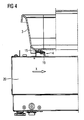
- Fig. 4
- shows the section B-B according to
Fig. 3 , - Fig. 5
- shows a perspective view onto the bottom side of the drawer,
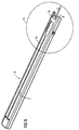
- Fig. 6
- shows a perspective view of a rail on which the drawer is guided,
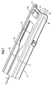
- Fig. 7
- shows an enlarged depiction of feature "A" according to
Fig. 6 and - Fig. 8a Fig. 8b and Fig. 8c
- show different embodiments of a holding element being arranged at the bottom side of the drawer.
- In
Fig. 1 adomestic oven 1 is shown schematically which has acooking cavity 2. Adrawer 3 on which food can be placed is arranged on tworails 4. Thedrawer 3 can be pulled out of the cavity in a slide direction y. - In
Fig. 2 to Fig. 7 details of an embodiment of the invention is depicted. -
Fig. 2 shows a plinth 20 which is arranged in the bottom region of thecavity 2. Tworails 4 are arranged in the side region of the plinth 20; thedrawer 3 can slide on therails 4 to be moved forth and back in the slide direction y. - In the synopsis of
Fig. 3 to Fig. 7 is can be seen that eachrail 4 is symmetrically to a plane which is arranged vertically and contains the slide direction y. - In the
bottom side 6 of the drawer 3 - seeFig. 5 - two slidingsurfaces 5 are arranged which are running parallel to another in the side regions of thedrawer 3. The slidingsurfaces 5 are formed byrib elements 15 which are located in the bottom of thedrawer 3.Holding elements 8 are arranged at one end of therib elements 15. The holdingelements 8 have a cross section - seen in slide direction y - as schematically shown for three examples inFig. 8a, 8b and 8c , see below. - Each
rail 4 is formed from a sheet metal strip by deforming. It has two lowerflat bands flat band 12. The upperflat band 12 is connected with the lowerflat bands flat connection bands 13 and 14 (seeFig. 7 ). A top surface 7 is formed on one of the lower flat bands which is contacted by the slidingsurface 5 of therib elements 15 of thedrawer 3. - Furthermore, a
bottom surface 9 is formed by the bottom side of the upper flat band 12 (seeFig. 7 ). The upperflat band 12 has aslot 16 which extends along most of the extension of therail 4. - As can be seen from
Fig. 8a, 8b and 8c the holdingelement 8 extends along a certain extension vertically downward from thedrawer 3. Thus, the holdingelement 8 penetrates theslot 16 downwards. Under the upperflat band 12 thebottom surface 9 is established. A part of the holdingelement 8 finds here a sliding counter face due to the circumstance that the holding element has e. g. a T-shaped form (seeFig. 8a ) or a L-shaped form (seeFig. 8b ) or a Z-shaped form (seeFig. 8c ). - To mount the
drawer 3 into therails 4 the holdingelements 8 are fed through a cut out 17 in therail 4. When pushing thedrawer 3 in slide direction y a chamferedtransition zone 18 makes sure that the holdingelements 8 are easily fed into theslot 16. - For a good guidance a bridge-
like guiding element 19 is formed at one end of therail 4. This element is formed from the material of therail 4 by deforming. - By the proposed design a cheap arrangement is created which comes up with a sufficient guiding comfort and a prevention of tiling of the
drawer 3 when pulling it out of the cavity. -
- 1
- Oven (domestic oven)
- 2
- Cavity
- 3
- Drawer
- 4
- Rail
- 5
- Sliding surface
- 6
- Bottom side
- 7
- Top surface
- 8
- Holding element
- 9
- Bottom surface
- 10
- Lower flat band
- 11
- Lower flat band
- 12
- Upper flat band
- 13
- Flat connection band
- 14
- Flat connection band
- 15
- Rib element
- 16
- Slot
- 17
- Cut out
- 18
- Chamfered transition zone
- 19
- Guiding element
- 20
- Plinth
- y
- Slide direction
Claims (15)
- Oven (1), especially domestic oven, comprising a cavity (2), wherein at least one drawer (3) is arranged in the cavity (2), wherein the drawer (3) can be moved relatively to the cavity (2) in a horizontal slide direction (y), wherein at least two longitudinal extending rails (4) are arranged parallel to another in the cavity (2) and being oriented into the slide direction (y) and wherein the drawer (3) is arranged slidable on the rails (4),
characterized in that
the drawer (3) has at least two sliding surfaces (5) at its bottom side (6), which sliding surfaces (5) are arranged for sliding on a top surface (7) of the rails (4), wherein the drawer (3) has at least two holding elements (8) at its bottom side (6) which holding elements (8) are arranged for sliding on a bottom surface (9) of the rails (4). - Oven according to claim 1, characterized in that the rails (4) have a cross section consisting of two lower flat bands (10, 11) extending in a horizontal plane and an upper flat band (12) extending in a horizontal plane.
- Oven according to claim 2, characterized in that the rails (4) have two flat connection bands (13, 14) extending in a vertical plane and connecting the upper flat band (12) with the two lower flat bands (10, 11).
- Oven according to claim 2 or 3, characterized in that the bottom surface (9) of the rail (4) is arranged at the bottom side of the upper flat band (12).
- Oven according to one of claims 2 to 4, characterized in that the top surface (7) of the rail (4) is arranged at the upper side of one of the lower flat bands (10, 11).
- Oven according to one of claims 1 to 5, characterized in that the sliding surfaces (5) of the drawer (3) are formed by at least two rib elements (15) which are arranged at the bottom side (6) of the drawer (2).
- Oven according to one of claims 1 to 6, characterized in that the holding element (8) is formed by a L-shaped or T-shaped or Z-shaped rib part which is fixed at the bottom side of the drawer (3).
- Oven according to one of claims 1 to 7, characterized in that the holding element (8) is arranged at one end of the drawer (3) seen in slide direction (y).
- Oven according to claim 8, characterized in that the length of the holding element (8) in slide direction (y) is below 15 of the length of the drawer (3) in slide direction (y).
- Oven according to one of claims 7 to 9, characterized in that the rail (4) has a longitudinal extending slot (16), wherein a vertically extending part of the holding element (8) of the drawer (3) is penetrating the slot (16).
- Oven according to claim 10, characterized in that the rail (4) has a cut out (17) adjacent to one end of the slot (16) with a bigger size than the size of the slot (16) for receiving the holding element (8).
- Oven according to claim 11, characterized in that the rail (4) has a chamfered transition zone (18) between the cut out (17) and the slot (16).
- Oven according to one of claims 6 to 12, characterized in that the rail (4) has a guiding element (19) at one of its axial ends forming a guiding surface for the rib element (15).
- Oven according to claim 13, characterized in that the rail (4) is made of a sheet metal part, wherein the guiding element (19) is produced by deformation of a section of the sheet metal part.
- Oven according to one of claims 1 to 14, characterized in that the rail (4) is symmetrically to a plane being arranged vertically and extending in the slide direction (y).
Priority Applications (1)
| Application Number | Priority Date | Filing Date | Title |
|---|---|---|---|
| EP11002629A EP2505926A1 (en) | 2011-03-30 | 2011-03-30 | Oven, especially domestic oven |
Applications Claiming Priority (1)
| Application Number | Priority Date | Filing Date | Title |
|---|---|---|---|
| EP11002629A EP2505926A1 (en) | 2011-03-30 | 2011-03-30 | Oven, especially domestic oven |
Publications (1)
| Publication Number | Publication Date |
|---|---|
| EP2505926A1 true EP2505926A1 (en) | 2012-10-03 |
Family
ID=44260148
Family Applications (1)
| Application Number | Title | Priority Date | Filing Date |
|---|---|---|---|
| EP11002629A Withdrawn EP2505926A1 (en) | 2011-03-30 | 2011-03-30 | Oven, especially domestic oven |
Country Status (1)
| Country | Link |
|---|---|
| EP (1) | EP2505926A1 (en) |
Citations (7)
| Publication number | Priority date | Publication date | Assignee | Title |
|---|---|---|---|---|
| US2597684A (en) * | 1950-06-08 | 1952-05-20 | Jack W Stringe | Drawer hook |
| DE2422633A1 (en) * | 1974-05-10 | 1975-11-20 | Kefi Verwertungs Ag | Oven tray with welded retainer lugs - avoiding possibility of slipping, without hindering cleaning |
| GB2047076A (en) | 1979-04-12 | 1980-11-26 | Lb Plastics Ltd | Drawer runners |
| JPS6421044A (en) | 1987-07-15 | 1989-01-24 | Furukawa Aluminium | Aluminum-alloy sheet for can lid |
| EP0406703A1 (en) | 1989-07-06 | 1991-01-09 | Arturo Salice S.p.A. | Slide for drawers and the like |
| DE19847727C2 (en) | 1998-10-16 | 2000-09-28 | Aeg Hausgeraete Gmbh | Telescopic pull-out device for food carriers in the cooking space of household ovens |
| DE10054954B4 (en) | 2000-11-06 | 2004-10-21 | AEG Hausgeräte GmbH | Cooking oven with pull-out device for food carriers |
-
2011
- 2011-03-30 EP EP11002629A patent/EP2505926A1/en not_active Withdrawn
Patent Citations (7)
| Publication number | Priority date | Publication date | Assignee | Title |
|---|---|---|---|---|
| US2597684A (en) * | 1950-06-08 | 1952-05-20 | Jack W Stringe | Drawer hook |
| DE2422633A1 (en) * | 1974-05-10 | 1975-11-20 | Kefi Verwertungs Ag | Oven tray with welded retainer lugs - avoiding possibility of slipping, without hindering cleaning |
| GB2047076A (en) | 1979-04-12 | 1980-11-26 | Lb Plastics Ltd | Drawer runners |
| JPS6421044A (en) | 1987-07-15 | 1989-01-24 | Furukawa Aluminium | Aluminum-alloy sheet for can lid |
| EP0406703A1 (en) | 1989-07-06 | 1991-01-09 | Arturo Salice S.p.A. | Slide for drawers and the like |
| DE19847727C2 (en) | 1998-10-16 | 2000-09-28 | Aeg Hausgeraete Gmbh | Telescopic pull-out device for food carriers in the cooking space of household ovens |
| DE10054954B4 (en) | 2000-11-06 | 2004-10-21 | AEG Hausgeräte GmbH | Cooking oven with pull-out device for food carriers |
Similar Documents
| Publication | Publication Date | Title |
|---|---|---|
| KR101796117B1 (en) | Pull-out guide | |
| CN103220943B (en) | Pull-out guide for a pull-out part of a piece of furniture | |
| KR20100134696A (en) | Plug-in pull-out guide | |
| RU2016125126A (en) | METHOD FOR MANUFACTURING A COMPONENT WITH A ROOT CROSS-SECTION | |
| US20160316909A1 (en) | Drawer wall element | |
| US11905713B2 (en) | Coupling system for mounting tiles to a building | |
| KR20130097710A (en) | Cabinet having a pull-out part | |
| JP2009527711A (en) | Linear bearing guide rail | |
| KR20130103777A (en) | A pull-out guide in the form of a full-extension mechanism for a pull-out part of a piece of furniture | |
| JP2016211599A5 (en) | ||
| EP2772693A1 (en) | Encasing for household appliances | |
| EP2436990B1 (en) | Cooking device | |
| EP2795011B1 (en) | Inverted t main runner for forming support structures for false ceilings | |
| EP3014716B1 (en) | Mounting frame and rail for electronics and instrumentation enclosure | |
| RU2010117375A (en) | MODULAR ELEMENT FOR MAKING FIXED STAIRS | |
| KR102127834B1 (en) | Apparatus for replacing the bend support of the bending machine | |
| EP3141850A1 (en) | A shelf system | |
| ITGE20060016U1 (en) | QUICK FIXING SYSTEM | |
| EP1788681B9 (en) | Engageable stretch of cable trays | |
| EP2706163A2 (en) | Inverted T profile for forming false ceiling support structures | |
| CN105636481B (en) | Floating support rollers | |
| CN103200843A (en) | Carrier rail for a drawer base | |
| EP2826402B1 (en) | Vertical column configured to equip a lateral panel of a shelving device, lateral panel comprising such vertical columns and shelving device comprising such lateral panels | |
| JP5929247B2 (en) | Linear motion device | |
| KR200465481Y1 (en) | Ground terminal block |
Legal Events
| Date | Code | Title | Description |
|---|---|---|---|
| PUAI | Public reference made under article 153(3) epc to a published international application that has entered the european phase |
Free format text: ORIGINAL CODE: 0009012 |
|
| 17P | Request for examination filed |
Effective date: 20111012 |
|
| AK | Designated contracting states |
Kind code of ref document: A1 Designated state(s): AL AT BE BG CH CY CZ DE DK EE ES FI FR GB GR HR HU IE IS IT LI LT LU LV MC MK MT NL NO PL PT RO RS SE SI SK SM TR |
|
| AX | Request for extension of the european patent |
Extension state: BA ME |
|
| 17Q | First examination report despatched |
Effective date: 20160415 |
|
| STAA | Information on the status of an ep patent application or granted ep patent |
Free format text: STATUS: THE APPLICATION IS DEEMED TO BE WITHDRAWN |
|
| 18D | Application deemed to be withdrawn |
Effective date: 20160628 |